

Panasonic WV-CF250 User Manual
Colour CCTV Camera
WV-CF250
WV-CF254
ENGLISH
DEUTSCHFRANÇAISESPAÑOL
Before attempting to connect or operate this product, please read these instructions completely
ENGLISH VERSION
CAUTION
RISK OF ELECTRIC SHOCK
DO NOT OPEN
CAUTION:
TO REDUCE THE RISK OF ELECTRIC SHOCK,
DO NOT REMOVE COVER (OR BACK), NO
USER SERVICEABLE PARTS INSIDE.
REFER SERVICING TO QUALIFIED SERVICE
PERSONNEL.
The lightning flash with arrowhead symbol, within an equilateral triangle, is
interned to alert the user to the presence of uninsulated "dangerous voltage" within the product's enclosure that
may be of sufficient magnitude to constitute a risk of electric shock to persons.
The exclamation point within an equilateral triangle is intended to alert the user
to the presence of important operating
and maintenance (servicing) instructions in the literature accompanying the
appliance.
The serial number of this product may be found on the
top of the unit.
You should note the serial number of this unit in the
space provided and retain this book as a permanent
record of your purchase to aid identification in the event
of theft.
Model No.
Serial No.
For Australia
To ensure safe operation the three-pin plug must be inserted only
into a standard three-pin power point which is effectively earthed
through the normal household wiring. Extension cords used with
the equipment must be three-core and be correctly wired to provide connection to earth. Wrongly wired extension cords are a
major cause of fatalities.
The fact that the equipment operates satisfactorily does not imply
that the power point is earthed and that the installation is completely safe. For your safety, if in any doubt about the effective
earthing of the power point, consult a qualified electrician.
FOR YOUR SAFETY PLEASE READ THE FOLLOWING TEXT CAREFULLY.
The wires in this mains lead are coloured in accordance with the following code.
As the colours of the wire in the mains lead of this appliance may
not correspond with the coloured markings identifying the terminals in
your plug, proceed as follows.
The wire which is coloured green-and-yellow must be connected to
the terminal in the plug which is marked with the letter E or by the earth
symbol I or coloured green or green-and-yellow.
The wire which is coloured blue must be connected to the terminal
in the plug which is marked with the letter N or coloured black.
The wire which is coloured brown must be connected to the terminal in the plug which is marked with the letter L or coloured red.
THIS APPARATUS MUST BE EARTHED.
For U.K.
THIS APPARATUS MUST BE EARTHED.
Green-and-yellow: Earth
Blue: Neutral
Brown: Live
WARNING
IMPORTANT
WARNING:
TO PREVENT FIRE OR ELECTRIC SHOCK HAZARD, DO NOT EXPOSE THIS APPLIANCE TO RAIN OR
MOISTURE.

CONTENTS
PREFACE ............................................................................................................................................................ 2
FEATURES .......................................................................................................................................................... 2
PRECAUTIONS ................................................................................................................................................... 2
MAJOR OPERATING CONTROLS AND THEIR FUNCTIONS ............................................................................. 3
CONNECTIONS .................................................................................................................................................. 5
INSTALLATION ..................................................................................................................................................... 6
ADJUSTMENT ....................................................................................................................................................... 9
SYSTEM CONNECTION ...................................................................................................................................... 11
SETUP ................................................................................................................................................................. 12
1. CAMERA SETUP MENU ............................................................................................................................... 12
2. SETUP OPERATION ..................................................................................................................................... 12
SETTING PROCEDURES .................................................................................................................................... 15
PREVENTION OF BLOOMING AND SMEAR ...................................................................................................... 20
SPECIFICATIONS ................................................................................................................................................ 21
STANDARD ACCESSORY ................................................................................................................................... 21
OPTIONAL ACCESSORIES ................................................................................................................................. 21
ENGLISH
We declare under our sole responsibility that the product to
which this declaration relates is in conformity with the standards or other normative documents following the provisions of
Directives EEC/73/23 and EEC/89/336.
Noi dichiariamo sotto nostra esclusiva responsabilità che il
prodotto a cui si riferisce la presente dichiarazione risulta conforme ai seguenti standard o altri documenti normativi conformi
alle disposizioni delle direttive CEE/73/23 e CEE/89/336.
Wij verklaren als enige aansprakelijke, dat het product waarop
deze verklaring betrekking heeft, voldoet aan de volgende normen of andere normatiefve dokumenten, overeenkomstig de
bepalingen van Richtlijnen 73/23/EEC en 89/336/EEC.
Vi erklærer os eneansvarlige for, at dette produkt, som denne
deklaration omhandler, er i overensstemmelse med den
følgende standarder eller andre normative dokumenter i følge
bestemmelserne i direktivene 73/23/EEC og 89/336/EEC.
The model numbers in these Operating Instructions are given without suffix.
Vi deklarerar härmed värt fulla ansvar för att den produkt till
vilken denna deklaration hänvisar är i överensstämmelse med
standarddokument, eller andra normativa dokument som
framstölls i Direktiv 73/23/EEC och 89/336/EEC.
Ilmoitamme yksinomaisella vastuullamme, että tuote, jota tämä
ilmoitus koskee, noudattaa seuraavia standardeja tai muita
ohjeellisia asiakirjoja, jotka noudattavat direktiivien 73/23/EEC
ia 89/336/EEC. säädöksiä.
Vi erklærer oss alene ansvarlige for at produktet som denne
erklæringen gjelder for, er i overensstemmelse med følgende
normer eller andre normgivende dokumenter som fælger
bestemmelsene i direktiven 73/23/EEC og 89/336/EEC.
-1-

PREF ACE
PRECAUTIONS
Panasonic's WV-CF250 series colour digital camera introduces a new level of high picture quality
and high resolution through the use of a 1/3-inch
interline transfer CCD image sensor having 753
horizontal pixels (picture elements), and digital signal processing LSIs. This model offers cutting-edge
technology for advanced video surveillance.
FEATURES
1. The following functions are built in.
(1) The SUPER-D function eliminates interfer-
ence by strong background lighting which
makes the camera picture dark, such as a
spotlight.
Dynamic range of 42 dB.
(2) Auto/Manual White Balance Function
(3) Electronic Shutter Function
2. Camera with a built in Vari-Focal lens
3. Signal-to-noise ratio of 50 dB
4. Minimum illumination of 5 lux (0.5 footcandle).
5. 480 lines of horizontal resolution
6. High quality picture:
(a) 2H type vertical enhancer for greater pic-
ture sharpness
(b) Chroma averaging circuit for better colour
signal to noise ratio
(c) Minimum of aliasing on fine objects
(d) Expanded dynamic range by use of knee
circuit
(e) Highlight aperture correction for greater
picture detail of bright object
1. Do not attempt to disassemble the camera.
To prevent electric shock, do not remove
screws or covers.
There are no user serviceable parts inside. Ask
a qualified service person for servicing.
2. Handle the camera with care.
Do not abuse the camera. Avoid striking,
shaking, etc. The camera could be damaged
by improper handling or storage.
3. Do not expose the camera to rain or
moisture, or try to operate it in wet areas.
Turn the power off immediately and ask a qualified service person for servicing. Moisture can
damage the camera and also create the danger of electric shock.
4. Do not use strong or abrasive detergents
when cleaning the camera body.
Use a dry cloth to clean the camera when
dirty.
In case the dirt is hard to remove, use a mild
detergent and wipe gently.
5. Never face the camera towards the sun.
Do not aim the camera at bright objects.
Whether the camera is in use or not, never aim
it at the sun or other extremely bright objects.
Otherwise, blooming or smear may be caused.
6. Do not operate the camera beyond the
specified temperature, humidity or power
source ratings.
Use the camera under conditions where temperature is between −10°C - +50°C (14°F 122°F), and humidity is below 90%. The input
power source is 220 - 240V AC 50Hz for WVCF250 and 24V AC 50Hz for WV-CF254.
-2-
MAJOR OPERATING CONTROLS AND THEIR FUNCTIONS
OPEN
LOCK
OPEN
LOCK
LEFT RIGHT
SET
DOWN
UP
-3-

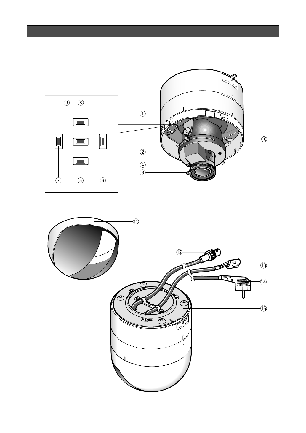
q Panning Table
This adjusts the panning angle of the camera.
w Camera Head
This adjusts the tilting angle of the camera.
e Focus Ring
This adjusts the focus.
r Zoom Ring
This adjusts the angle of view.
t (D) (Down Button)
This button moves the cursor downward. It
also selects items in the CAM SET UP menu.
y (R) (Right Button)
This button moves the cursor to the right. It
also selects the mode and adjusts some levels.
u (L) (Left Button)
This button moves the cursor to the left. It also
selects the mode and adjusts some levels.
i (U) (Up Button)
This button moves the cursor upward. It also
selects items in the CAM SET UP menu.
o (S) (Set Button)
This button activates a selected item in the
CAM SET UP menu.
!0 Lens Holders
These holders bring the picture in an upright
position on the monitor screen.
!1 Dome Cover
This protects the camera head.
!2 Video Output Cable with BNC Connector
This connector is used to connect with the
VIDEO IN connector of the monitor.
!3 Power Cable with MOLEX Connector
(for WV-CF254)
This cable is for connecting the 24 V AC power
supply cable.
!4 AC Power Cable (for WV-CF250)
This cable is for connecting the 220-240 V AC
power supply.
!54 Camera Fixing Bracket
This bracket holds the camera on the ceiling or
the wall.
-4-
Caution:
Connect to 24 V AC (19.5 V-28 V) class 2
power supply only. Make sure to connect
the grounding lead to the GND terminal
when the power is supplied from a 24 V AC
power source.
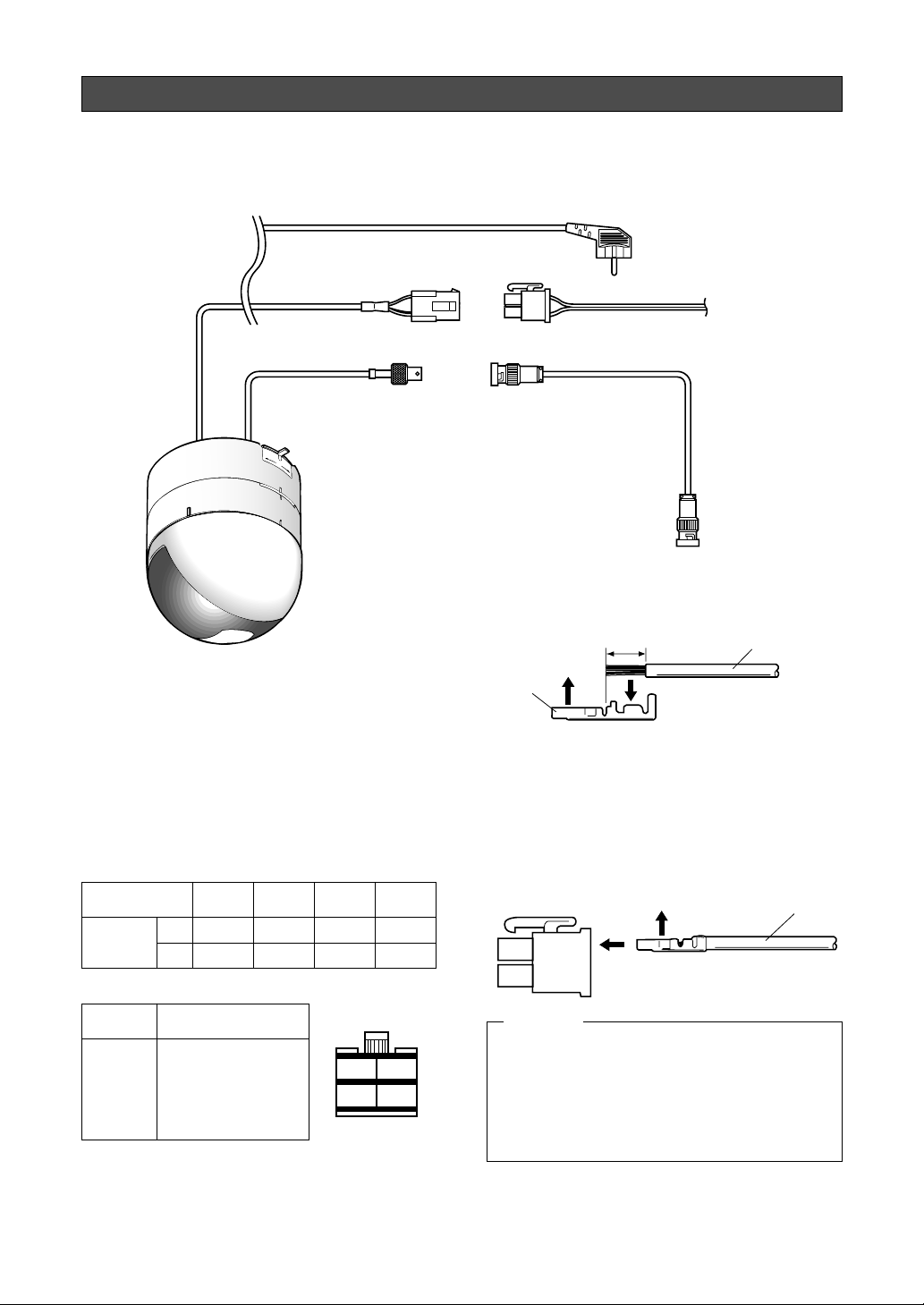
CONNECTION
Precaution:
The following connections should be made by qualified service personnel or system installers in accordance with the local codes.
220-240V AC (WV-CF250)
24V AC
(WV-CF254)
Coaxial Cable
Video Output Cable
OPEN
LOCK
• Power supply connection
A. WV-CF250 (220-240V AC 50Hz)
Connect the AC power cable to an electrical
outlet of 220-240V AC 50Hz.
B. WV-CF254 (24V AC 50Hz)
Connect the power cable with MOLEX connector according to the references below.
Recommended wire gauge sizes for 24 V AC line.
Copper wire size
(AWG)
Length
of Cable
(Approx.)
#24
(0.22mm
20 30 45 75
(m)
65 100 160 260
(ft)
2
)
(0.33mm
#22
Accessory Connector Information
#20
2
)
(0.52mm2)
#18
(0.83mm2)
BNC
Plug
Contact
To Video IN
(CAMERA IN)
A
Up
Approx.
3 mm (1/8 inch)
BNC Plug
Wire
Insert
Insert the wire until A position
and clamp the contacts.
Prepare the individual conductors for clamping.
Use MOLEX band tool part number 57027-5000
(for UL-Style Cable UL1015) or 57026-5000 (for ULStyle UL-1007) for clamping the contacts.
After clamping the contacts, push them into the
proper holes in the accessory connector of this
camera until they snap in place.
Up
Contact
Wire
Pin No. Power Source
1 :
2 :
3 :
4 :
24 V AC LIVE
24 V AC NEUTRAL
Ground
Not used
3
4
1
2
How to assemble the cable with the accessory
connector
Strip back the cable jacket approx. 3 mm (1/8 inch)
and separate the individual conductors.
CAUTION
Shrinking the cable-entry seal is a one-time
procedure. Do not shrink the cable-entry
seal until it has been ascertained that the
unit is functioning.
CONNECT THIS TO 24V AC CLASS 2
POWER SUPPLY ONLY.
-5-
INSTALLATION
REAR LOWER
FRONT UPPER
OPEN
LOCK
Important Notices:
• The following installation should be made by
qualified service personnel or system installers
and should confirm to all local codes.
• Be sure to use a ceiling board having enough
strength to support this camera.
1. Mounting the camera fixing bracket
1-1. Make a hole (diameter 75mm) in the ceiling
board in the desired location.
Ceiling board
1-2. Fix the camera fixing bracket onto the ceiling
board by using four camera fixing bracket
mounting screws (not provided).
Ceiling board
ø75 mm (ø2-15/16”)
Mounting hole
Camera
fixing bracket
Mounting screws (not provided)
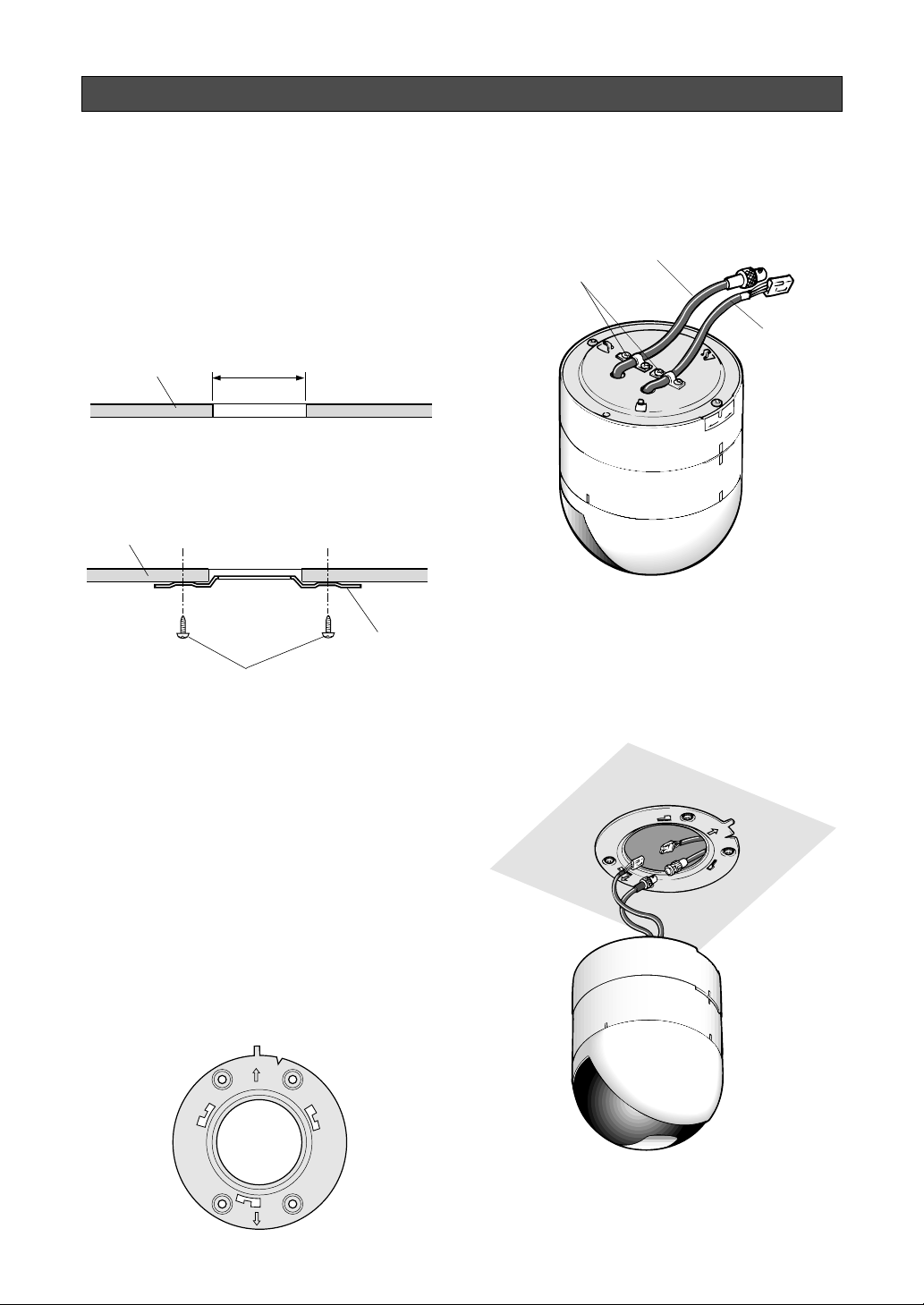
2. Mounting the camera onto the camera fixing bracket
2-1. Make sure the video output cable and power
cable are fixed by the coaxial cable clamps.
Video output cable
Coaxial cable clamps
Power cable
2-2. Pass the video output cable and power cable
through the hole in the camera fixing bracket,
and connect as described in the previous section “CONNECTION.”
Caution: Noise may be produced in the picture on
the monitor screen if the camera is installed on
metallic ceiling. To prevent the hum, using the
optional wall mounting bracket WV-Q103A is
recommended.
Note:
Before fixing the bracket with screws, confirm
the direction of the camera by checking the
position of signs “FRONT g UPPER” and
“REAR g LOWER” on the camera fixing brack-
et.
“FRONT g UPPER” sign indicates the direction of the camera head.
“REAR g LOWER” sign indicates the direction
opposite to the camera head.
-6-
 Loading...