

Panasonic wv-cf212x Operation Manual
1. Do not attempt to disassemble the camera.
To prevent electric shock, do not remove
screws or covers.
There are no user-serviceable parts inside.
Ask qualified service personnel for servicing.
2. Handle the camera with care.
Do not abuse the camera. Avoid striking,
shaking, etc. The camera could be damaged
by improper handling or storage.
3. Do not expose the camera to rain or
moisture, or try to operate it in wet areas.
Turn the power off immediately and ask qualified service personnel for servicing. Moisture
can damage the camera and also create the
danger of electric shock.
4. Do not use strong or abrasive detergents
when cleaning the camera body.
Use a dry cloth to clean the camera when
dirty.
In case the dirt is hard to remove, use a mild
detergent and wipe gently. Afterwards, wipe
off the remained part of the detergent in it
with a dry cloth.
5. Clean the lens faceplate with care.
Do not clean the lens with strong or abrasive
detergents. Use lens tissue or a cotton tipped
applicator and ethanol.
6. Never face the camera towards the sun.
Do not aim the camera at bright objects.
Whether the camera is in use or not, never
aim it at the sun or other extremely bright
objects. Otherwise, blooming or smear may
be caused.
7. Do not operate the camera beyond the
specified temperature, humidity or power
source ratings.
Use the camera under conditions where temperature is between –10 °C to +50 °C (14 °F to
122 °F), and humidity is below 90 %. The
input power source is 12 V DC, 240 mA.
8. It is recommended to use a monitor whose
resolution is at least equal to that of the
camera.
PRECAUTIONS
+12V
–
+12 V
-
q
w
e
r
o
u
i
y
t
AP Soft
AP Sharp
BLC OFF
BLC ON
ON
12
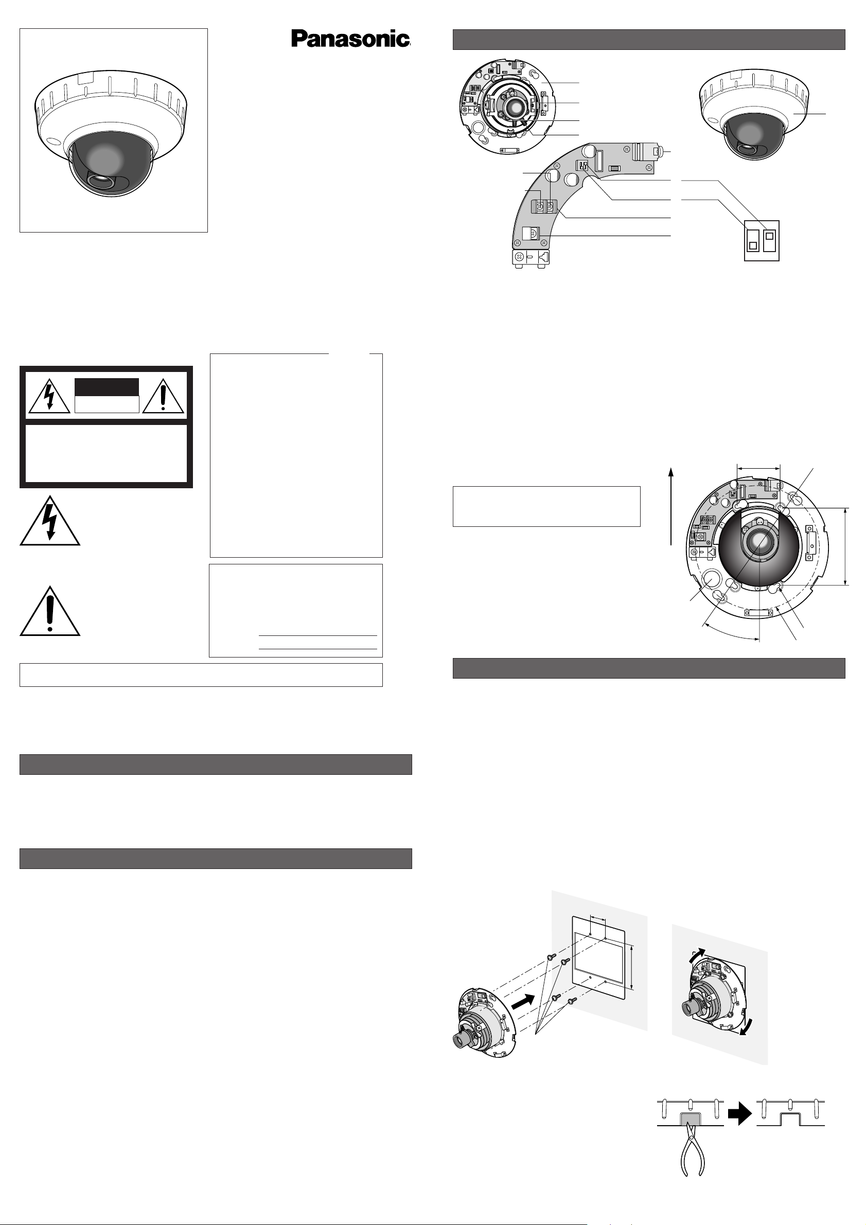
MAJOR OPERATING CONTROLS AND THEIR FUNCTIONS
q Camera Panel
w Panning/Tilting/Azimuth Table
Adjusts the panning/tilting angle of the camera.
e Focus Lever
Fixes the focus position after adjusting.
r Zoom Lever
Fixes the zoom position after adjusting.
t Video Output Terminal
Connects to the video input connector of a
monitor.
y DC 12 V Input Terminal
Connects to the 12 V DC, 240 mA power supply. Connection should be made in accordance with the !/@ signs of PCB.
u Back Light Compensation Mode Selector
(BLC ON, OFF)
ON: Select this when the brightness level of
the background is higher than the object.
OFF: Select this when you can view the
object without backlight.
The factory default setting is OFF.
i Aperture Level Selector (AP Sharp/Soft)
Sharp: Sharpens the image outline.
Soft: Softens the image outline.
The factory default setting is Sharp.
Note: Set the selector to Soft when a quad
system is connected to this camera.
o Video Jack (3.5 diam. mini jack)
Connect the LCD monitor and such devices
with 3.5 diam. 2-pole L-type plug for checking images.
!0 Panel Cover
!0
Caution: To prevent fire or electric shock haz-
ard, use a UL listed cable (WV-1, style
1007) for the DC 12 V Input Terminal.
Before attempting to connect or operate this product,
please read these instructions carefully and save this manual for future use.
Ns0902-1043 3TR001242BAA Printed in China
PREF ACE
Panasonic’s WV-CF212 series digital signal processing color CCD cameras uses a 1/4-inch interline transfer CCD image sensor having 768 horizontal pixels (picture elements), and digital signal
processing LSI’s. This model is designed for video
surveillance.
INSTALLATIONS
46 mm
(1.81")
83.5 mm (3.29")
Front / Upper
Cable access hole
35°
6-ø4.5(0.18")
ø130 (5.12")
Installation dimensional drawing
WARNING
• The following installation should be made by qualified service personnel or system installers and
should confirm to all local codes.
• Be sure to use a ceiling board/wall having enough strength to support this camera.
■ Camera mounting position
Notes:
• Remove the panel cover before the mounting procedure. (Refer to Step 1 to 4 of "How to mount the
camera" on the next page.)
• Procure four mounting screws locally.
To mount the camera on a junction box
Note: If you mount the camera on a junction box, procure one locally that meets the dimensions in the fig-
ure below.
1. Install the junction box to the wall/ceiling.
2. Attach the four mounting screws to the junction box.
3. Fix the camera and the junction box. Then, turn the camera clockwise.
4. Fasten all the mounting screws.
To mount the camera directly on the wall/ceiling
1. Cut out the panel according to the concave.
(Refer to the figure on the right.)
2. Prepare a space, which is ø155 mm (6.1") or
larger, on the wall/ceiling.
3. Attach the four mounting screws to the
wall/ceiling. (Refer to "Installation dimensional
drawing".)
4. Fix the camera and the wall/ceiling. Then,
turn the camera clockwise.
5. Fasten all the mounting screws.
The exclamation point within
an equilateral triangle is intended to alert the user to the presence of important operating
and maintenance (servicing)
instructions in the literature
accompanying the appliance.
The lightning flash with arrowhead symbol, within an equilateral triangle, is interned to alert
the user to the presence of
uninsulated "dangerous voltage" within the product's enclosure that may be of sufficient
magnitude to constitute a risk
of electric shock to persons.
The serial number of this product may be found
on the top of the unit.
You should note the serial number of this unit
in the space provided and retain this instruction
as a permanent record of your purchase to aid
identification in the event of theft.
Model No. WV-CF212
Serial No.
SA 1966
SA 1965
WARNING:
To reduce the risk of fire or electric shock, do not expose this appliance to rain or moisture.
CAUTION: TO REDUCE THE RISK OF ELECTRIC SHOCK,
DO NOT REMOVE COVER (OR BACK).
NO USER-SERVICEABLE PARTS INSIDE. REFER SER-
VICING TO QUALIFIED SERVICE PERSONNEL.
CAUTION
RISK OF ELECTRIC
SHOCK DO NOT OPEN
NOTE: This equipment has been tested and
found to comply with the limits for a Class A
digital device, pursuant to Part 15 of the FCC
Rules. These limits are designed to provide
reasonable protection against harmful interference when the equipment is operated in a
commercial environment. This equipment generates, uses, and can radiate radio frequency
energy and, if not installed and used in accordance with the instruction manual, may cause
harmful interference to radio communications.
Operation of this equipment in a residential
area is likely to cause harmful interference in
which case the user will be required to correct
the interference at his own expense.
FCC Caution: To assure continued compliance, (example - use only shielded interface
cables when connecting to computer or
peripheral devices). Any changes or modifications not expressly approved by the party
responsible for compliance could void the
user’s authority to operate this equipment.
For U.S.A
Color CCTV Camera
Operating Instructions
Model No. WV-CF212
Shown figure is an
example for junction box.
Camera mounting screw x 4
46 mm
(1-13/16")
83,5 mm
(3-5/16")
Power Cable
Connect the power cord to the 12 V DC input terminal.
WARNING
The following connections should be made by
qualified service personnel or system
installers.
Video Cable
Cable Preparation
Power cable (with sealing at the side of the
camera)
Cautions:
• Shrinking the cable-entry seal is a one-time
procedure. Do not shrink the cable-entry seal
until it has been ascertained that the unit is
functioning.
• To prevent fire or electric shock hazard, use
a UL listed cable (WV-1, style 1007) for the
DC 12 V Input Terminal.
• Do not mistake “+” and “–” when connecting
the power cable to the DC 12 V input terminal
of the camera. It may cause trouble.
20 mm (0.79") or less
Seal here.
CONNECTIONS
Copper wire
size (AWG)
Resistance of copper wire [at 20 °C (68 °F)]
Resistance
Ω/m
Resistance
Ω/ft
#24
(0.22mm
2
)
0.078
0.026
#22
(0.33mm2)
0.050
0.017
#20
(0.52mm2)
0.03
0.010
#18
(0.83mm2)
0.018
0.006
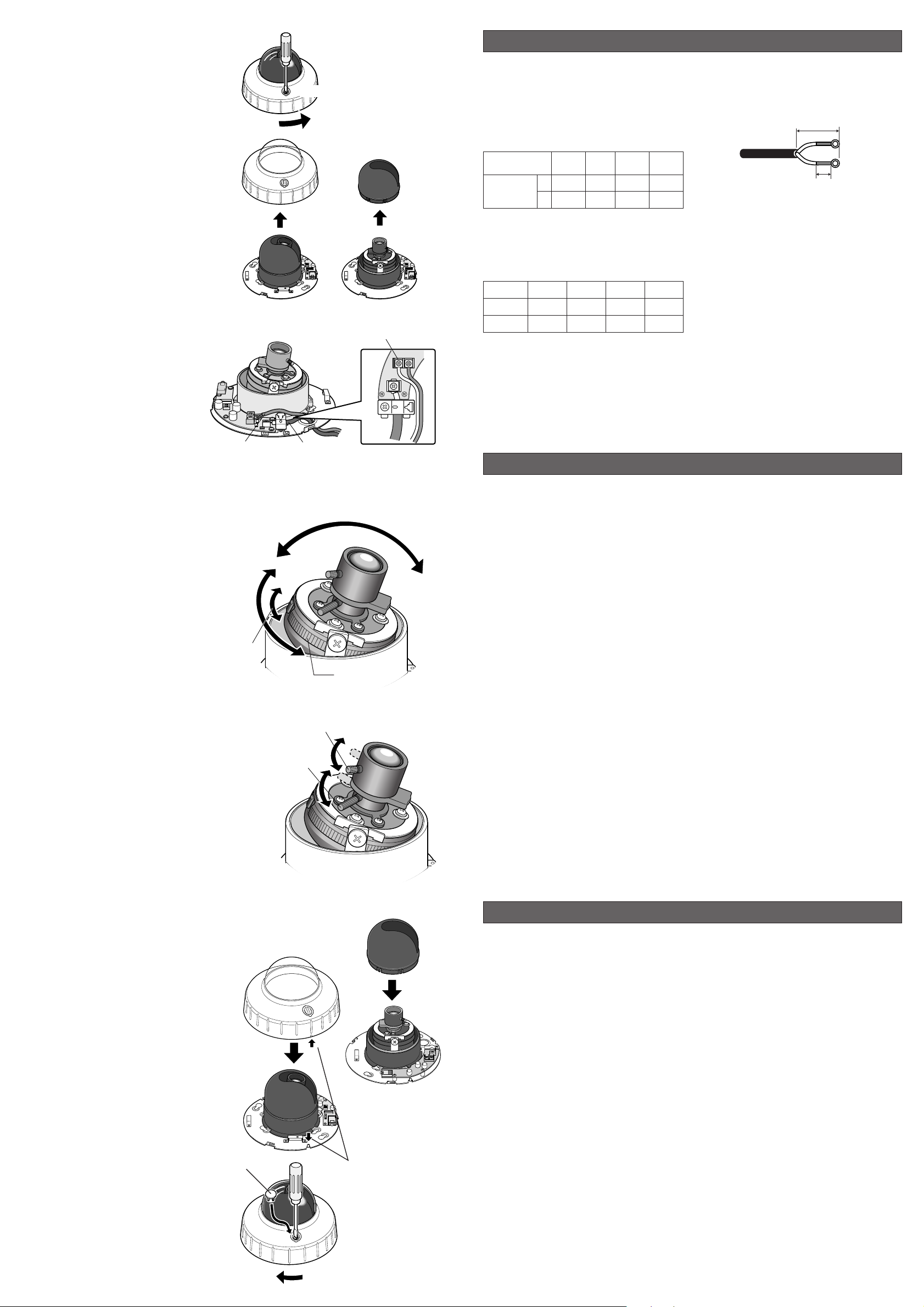
■ How to mount the camera
1. Remove the panel screw with a phillips
screwdriver. (Refer to the illustration on the
right.)
2. Turn the panel cover counter-clockwise.
3. Remove the panel cover.
4. Remove the inner dome.
5. Mount the camera on the junction box or ceiling/wall. (Refer to "Camera mounting position".)
6. Connect the power cable and the video
cable to the camera.
Note: The illustration on the right
assumes that you will use a junction
box. Pass the cables through the cabIe
access hole. If you mount the camera
directly on the wall/ceiling, cut out the
panel according to the concave. (Refer
to the previous page.
• Connect them to 12 V DC (10.5 V to 16
V) class 2 power supply only.
• To prevent fire or electric shock hazard, use a UL listed cable (VW-1, style 1007) for the Input
Terminal.
7. Adjust the panning, tilting and azimuth
while watching the LCD monitor. If the
image is slanting, move the azimuth
adjuster to obtain a leveled image.
Notes:
• You can check images by connecting an LCD monitor to the video jack.
However, images are not available
on the monitor connected to the
video cable connector.
• The signal from the video jack can
cause smear on the LCD monitor
when a high-luminance area is displayed.
• When you adjust panning/tilting/
azimuth, avoid holding the lens unit.
8. Adjust the zoom.
(1) Loosen the zoom lock screw at the tip of the
zoom lever by turning counter-clockwise.
(2) Adjust the zoom by moving the zoom lever.
(3) Turn the zoom lock screw clockwise to tighten
the zoom lever after adjustment.
9. Adjust the focus.
(1) Loosen the focus lock screw at the tip of the
focus lever by turning it counter-clockwise.
(2) Adjust the focus by moving the focus lever.
(3) Turn the focus lock screw clockwise to tighten
the focus level after adjustment.
Note: The focus should be adjusted after the
adjustments of panning, tilting, azimuth and
zoom.
10. After all the adjustments and connections
attach the inner dome to the camera.
11. Attach the panel cover to the camera.
The mark of the panel cover and the projection of the camera panel should be put
together.
Notes:
• Avoid covering the lens with the still part
the dome.
• Avoid pinching the cables between the
camera panel and the panel cover.
12. Fasten the panel screw with a phillips screwdriver. (Refer to the illustration on the right.)
13. Attach the supplied rubber cap to the camera, as shown in the figure on the right.
Pick-up device: 768 (H) x 492 (V) pixels, interline transfer CCD
Scanning area: 4.92 (H) x 3.70 (V) mm
(equivalent to scanning area of 1/4” pick-up tube)
Synchronization: Internal or multiplexed vertical drive (VD2), selectable
Scanning system: 2 : 1 interlace
Scanning: 525 lines / 60 fields / 30 frames
Horizontal: 15.734 kHz
Vertical: 59.94 Hz
Horizontal resolution: 480 lines
Video output: 1.0 V[p-p] NTSC composite 75 Ω
Automatic Gain Control (AGC): +18 dB
Automatic Tracing White Balance (ATW)
: ON only
Signal-to-noise ratio: 50 dB (equivalent to AGC Off, weight On)
Electronic light control: equivalent to continuous variable shutter speed between 1/60 s
and 1/15 000 s
Minimum illumination: 2.0 lx (0.2 foot-candle) at F1.4 (WIDE)
1.2 lx (0.12 foot-candle) at 20 IRE or more
Back Light Compensation (BLC): On or Off
Detail: Sharp or Soft, selectable
Panning range: ±100°
Tilting range: ±75°
Azimuth range: ±100°
Ambient operating temperature: –10 °C to +50 °C (14 °F to 122 °F)
Ambient operating humidity: Less than 90 %
Power source and
power consumption: 12 V DC, 240 mA
Dimensions: ø155 mm x 87 mm (H)
ø 6-1/10” x 3-2/5” (H)
Weights: 0.48 kg (1.06 lbs.)
Weights and dimensions indicated are approximate.
Specifications are subject to change without notice.
SPECIFICATIONS
STANDARD ACCESSORIES
Operating Instructions (this book)........................... 1 pc
Rubber cap ............................................................. 1 pc
Type of RG-59/U RG-6U RG-11/U RG-15/U
coaxial cable (3C-2V) (5C-2V) (7C-2V) (10C-2V)
Recommended (m) 250 500 600 800
maximum
cable length (ft) 825 1 650 1 980 2 640
• Calculation of the relation among the cable
length, resistance, and power supply:
10.5 V DC ≤ V
A
− 2(R x 0.24 x L) ≤ 16 V DC
L : Cable length (m)
R : Resistance of copper wire (Ω/m)
VA : DC output voltage of power supply unit
PANASONIC CANADA INC.
5770 Ambler Drive, Mississauga,
Ontario, L4W 2T3 Canada (905)624-5010
PANASONIC SALES COMPANY
DIVISION OF MATSUSHITA ELECTRIC OF PUERTO RICO INC.
San Gabriel Industrial Park 65th Infantry Ave. KM. 9.5 Carolina,
P.R. 00985 (809)750-4300
Panasonic Digital Communications & Security Company
Unit of Matsushita Electric Corporation of America
Security Systems Group
www.panasonic.com/cctv
Executive Office: One Panasonic Way 3E-7, Secaucus, New Jersey 07094
Zone Office
Eastern: One Panasonic Way, Secaucus, NJ 07094 (201) 348-7303
Central: 1707 N.Randal Road, Elgin, IL 60123 (847) 468-5205
Western: 6550 Katella Ave., Cypress, CA 90630 (714) 373-7840
2003 © Matsushita Electric Industrial Co., Ltd. All rights reserved.
Power cable
Pan
Azimuth
Zoom lever
(with lock function)
1. Remove the panel screw.
2. Turn the panel cover
counter-clockwise.
Inner dome
3. Remove
the panel cover.
Video cable
Tilt
Azimuth adjuster
Focus lever (with lock function)
4. Remove
the inner dome.
+12V DC
Rubber cap
Match the cover's mark
and the panel's projection.
 Loading...