

Panasonic WV-CF132N1E, WV-CF132T1E Installation Manual
Installation Guide
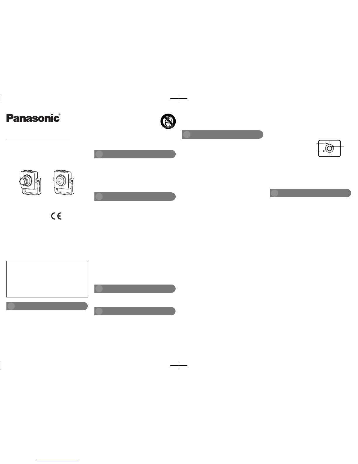
Color CCTV Camera
Model No.
WV-CF132N1E
WV-CF132T1E
Refer installation work to the dealer.
Installat ion work requires proper technique and experience. Failure to
observe this may cause injury or damage to the product.
Be sure to consult the dealer.
Do not attempt to disassemble or modify this product.
Failure to observe this may cause fire or electric shock.
Consult the dealer for repair or inspections.
Stop operation immediately when so mething is wrong with this
product.
When smoke or the smell of smoke comes from this product, stop operation immediately and contact your dealer.
In this case, turn the power off immediately and contact qualified service
personnel for service.
Ensure the installation site can bear the weight of the product.
Failure to observe this may cause a drop resulting in injury.
Installation work shall be started after sufficient reinforcement.
Periodic inspections shall be conducted.
Rust on the metal parts or screws may cause the falling of the product,
thus resulting in injury.
Consult the dealer for inspections.
Do not install this product in locations subject to vibration.
Constant vibration easily leads to loose screws or nuts, which may cause
the falling of the product, thus resulting in injury.
Do not strike or give a strong shock to this product.
Failure to observe this may cause fire or injury.
Turn off the power before wiring.
Failure to observe this may cause electric shock. Short circuit or wrong wiring
may lead to a fire.
Do not put the product near inflammable gas.
Failure to observe this may cause an explosion and injury.
Avoid installing this product in locations where salt damage occurs
or corrosive gas is produced.
Otherwise the in stallation por tion will deteriorate and a falling accident
may occur.
The screws and bolts must be tightened to the specified torque.
Loosening of mounting screws or bolts may cause a fall of the product
resulting in injury or accidents.
[Precautions for use]
The product is designed for indoor use.
This product has no power switch.
When turning off the power, turn off a power supply or remove a power cable.
To keep on using with stable performance
Do not use this product under hot and humid condition s. Fa ilure to
observe this may c ause com ponent de gradation, thus resulting in life
shortening of this product.
(Recommended temperature: +35 °C or below)
Do not expose this product to direct heat sources such as a heater, radiator or an electrothermal furnace.
Handle this product with care.
Be cautious when using this product to keep it free from strong impact or
vibration.
Otherwise it may cause malfunction.
Do not touch the lens with your hands.
Otherwise the lens may be stained, thus decreasing the image quality.
Noise points on the image
This product com es with a sup er sensitive CCD, so nois e points may
appear on the image. This is not a fault.
Panasonic assumes no responsibility for injuries or property damage resulti ng from failures arising out of improper installation or
operation inconsistent with this documentation.
The product is designed for indoor use.
Do not expose this camera to direct sunlight for hours and do not install
the product near a heater or an air conditioner. Otherwise, it may cause
deformation, discoloration and malfunction.
Keep the product far away from water and a damp environment.
Installation position
Consult your dealer about the installation position, and be sure to select a
firm site for installation.
• Install the product on a ceiling (such as a concrete ceiling) with sufficient
strength.
• Install the main unit of the camera at the fundamental part of the building or a portion with sufficient strength.
• If a site such as a plaster board is too weak to support the total weight,
the installation position shall be sufficiently reinforced.
Do not place this product in the following places:
• Locations directly subject to direct splashing of rain or water
• Locations where a chemical agent is used such as a swimming pool
• Loc ations subj ect to moisture or oil smo ke s uch as a ki tchen or
machine shop
• Locations that have a specific environment that is subject to an inflammable atmosphere
• Locations where radiation, an X-ray, a strong radio wave or a strong magnetic field is generated
• Locations where corrosive gas is produced, or locations where it may
be damaged by briny air such as seashores
• Locations where the temperature is beyond the range of -10 °C to +65 °C
• Locations subject to vibrations, such as on vehicles, marine vessels, or
above product lines (This product is not designed for on-vehicle use.)
• Locations subject to condensation as the result of severe changes in
temperature
Do not install the camera at a damp and dusty site
Otherwise the service life of internal parts may be shortened.
Do not install the camera at a site with high amounts of noise.
Noises m ay exist at a site near an air conditioner, an air freshener or a
vending machine.
Do not perform installation or wiring during thunder and lightning;
otherwise it may lead to a fire or electric shock.
Make sure to remove this product if it will no longer be used.
Do not damage the power plug or cable.
All the illustrations in this manual are based on WV-CF132N1E unless the
model is specified.
Before a ttempting to connect or operate this product, please read these
instructions carefully and save this manual for future use.
The model number is abbreviated in some descriptions in this manual.
WARNING:
• To prevent fire or electric shock hazard, do not expose this apparatus to rain or moisture.
• To prevent injury, this apparatus must be securely attached to the
wall/ceiling in accordance with the installation instructions.
• The connections should comply with local electrical code.
• This product has no power switch. When turning off the power,
turn off a Power Supply or remove a power cable.
• The installation shall be carried out in accordance with all applicable installation rules.
WV-CF132N1E
WV-CF132T1E
CCD color filter deterioration
When continuously shooting a bright light source such as a spotlight, the
color filter in the CCD may become deteriorated and this may cause discoloration to the affected part. Even when changing the fixed shooting
direction after continuously shooting a spotlight for a certain period, the
discoloration may remain.
Do not expose the camera to any direct intense light source such
as a spotlight.
The intense light source may
lead to dimming (mistiness)
or blooming (vertical lines) of
the image.
Cleaning the product
Be sure to turn off the power before cleaning to prevent electric shock.
Do not use diluent, benzene or other volatile chemical reagents to clean
the product; otherwise it may lead to discoloration of the shell.
About synchronous mode settings
The image synchronous mode of the product is internal synchronization
(INT) only. When a Panasonic system controller is connected, set the multiplexing vertical drive (VD2) to the off status.
Precautions
Precautions for installation
A brand new high resolution CCD
The newly developed 976-horizontal pixel CCD can achieve the horizontal
definition 650TV line.
Noise reduction, high sensitivity
With the introduction of low noise circuit design, this product enables the
following sensitivity of minimum illumination for color images:
0.04 lx (F1.2 equivalence) (color mode), 0.02 lx (F1.2 equivalence) (black
and white mode)
Features
THIS PUBLICATION IS PROVIDED “AS IS” WITHO UT WARRANTY OF
ANY KIND, EIT HER EXPRESS OR IMPLI ED, INCLUDIN G BU T NO T
LIMI TED TO, THE IMPLI ED W ARRANTI ES OF M ERCHAN TABILITY,
FITNESS FOR ANY PARTICULAR PURPOSE, OR NON-INFRINGEMENT
OF THE THIRD PARTY’S RIGHT.
THIS PUBLICATION COULD INCLUDE TECHNICAL INACCURACIES OR
TY POG RAP HIC AL ER ROR S. CH ANG ES A RE AD DED TO TH E
INFORMATION HEREIN, AT ANY TIME, FOR THE IMPROVEMENTS OF
THIS PUBLICATION AND/OR THE CORRESPONDING PRODUCT (S).
Limitation of liability
This product is a color CCTV camera that comes with a 1/3 type CCD. If
connected to a video monitor, this product can be used as a monitoring
system.
Preface
IN NO EVENT SHALL Panasonic System Networks Co., Ltd. BE LIABLE
TO A NY PARTY OR ANY P ERSON, EXCEPT FOR REPLACEMENT OR
REASONABLE MAINTENANCE OF THE PRODUCT, FOR THE CASES,
INCLUDING BUT NOT LIMITED TO BELOW:
(1) ANY LOS S O R D AMAGE, IN CLUDING WI THOUT LIM ITATION,
DI RE CT O R IN DIR EC T, SP ECI AL , CO NSE QU ENT IAL OR
EXEMPLARY, ARISING OUT OF OR RELATING TO THE PRODUCT;
(2) AN Y INC ONV ENI ENC E, LO SS, O R DA MAG E CAU SED B Y
INAPPROPRIATE USE OR NEGLIGENT OPERATION OF THE USER;
(3) ALL MAL FUNCTIO NS OR T ROUBLE S FR OM UNAUTHO RIZED
DISASSEMBLE, REPAIR OR MODIFICATION OF THE PRODUCT BY THE
USER, REGARDLESS OF THE CAUSE OF THE MALFUNCTION OR
TROUBLE;
(4) INCONVEN IENCE OR ANY LOSS ARISING WHEN IMAGES ARE
NOT DIS PLAYED, DUE TO ANY REASON OR CAUSE INCLUDING
ANY FAILURE OR PROBLEM OF THE PRODUCT;
(5) ANY PROBLEM, CONSEQUENTI AL INCON VENIENCE, OR LOS S
OR DAMAGE, ARISING OUT OF THE SYSTEM COMBINED BY THE
DEVICES OF THIRD PARTY;
(6) ANY CLAIM OR ACTION FOR DAMAGES, BROUGHT BY ANY PERSON
OR ORGANIZATION BEING A PHOTOG ENIC SUB JECT, DUE TO
VIOLATION OF PRIVACY WITH THE RESULT OF THAT SURVEILLANCECAMERA’S PICTURE, INCLUDING SAVED DATA, FOR SOME REASON,
BECOMES PUBLIC OR IS USED FOR ANY PURPOSE;
Disclaimer of warranty
sL0514-1054 PGQX1619YA Printed in China
Panasonic Corporation
http://panasonic.net
Panasonic System Networks Co., Ltd.
Fukuoka, Japan
Authorised Representative in EU:
Panasonic Testing Centre
Panasonic Marketing Europe GmbH
Winsbergring 15, 22525 Hamburg, Germany
© Panasonic System Networks Co., Ltd. 2014
Blooming
Dimming
Bright
object
Important safety instructions
1) Read these instructions.
2) Keep these instructions.
3) Heed all warnings.
4) Follow all instructions.
5) Do not use this apparatus near water.
6) Clean only with dry cloth.
7) Do not block any ventilation openings. Install in accordance with the
manufacturer’s instructions.
8) Do not install near any heat sources such as radiators, heat registers,
stoves, or other apparatus (including amplifiers) that produce heat.
9) Only use attachments/accessories specified by the manufacturer.
10) Use only with the cart, stand, tripod, bracket, or table
specified by the manufacturer, or sold with the apparatus. When a cart is used, use caution when moving
the cart/apparatus c ombination to avoid injury from
tip-over.
11) Refer all servicing to qualified service personnel. Servicing is required
when the apparatus has been damaged in any way, such as powersupply cord or p lug is damaged, liquid has been spilled or objects
have fallen into the apparatus, the apparatus has been exposed to
rain or moisture, does not operate normally, or has been dropped.
Black-and-white control (D&N)
Since the image can automatically switch to the black and white mode
from the color mode in the case of low illumination, you need not change
the settings at night.
S3125A
Adjusting the camera angle (excluding open hole mounting)
• Before fixing the mount bracket (accessory), adjust the direction horizontally as needed.
• Hold the camera and adjust the tilt angle (the angle range is limitless).
• Adjust the direction of the lens while confirming the image displayed on
the monitor.
• After the camera angle is adjusted properly, tighten the bracket fixing
screws (accessory).
(Recommended tightening torque: 0.12 N∙m {1.2 kgf∙cm})
Caution:
• The focal length has been set to the optimum value before delivery
of the product.
Power source
and consumption
12 V DC, 120 mA
Image sensor 1/3-type interline transfer CCD
Effective pixels 976 (H) × 582 (V)
Important
• When instal ling a scre w, be carefu l to preve nt th e cab le fro m
winding the screw.
• Two mounting screws (M2) are required to install the mount bracket.
Prepare them according to the material of the installation site. In this
case, wood screws and nails should not be used.
When mounting the camera on a concrete ceiling, use a plug bolt
(M2) for securing.
(Recommended tightening torque (M2): 0.2 N∙m {2 kgf∙cm})
Caution:
• ONLY CONNECT <12 V DC> CLASS 2 POWER SUPPLY (UL 1310/
CSA 223) or LIMITED POWER SOURCE (IEC/EN/UL/CSA 60950-1).
Connect a coaxial cable (locally procured)
Important
• Before connection, be sure to turn off the power of each device.
• Be sure to connect the coaxial cable plug firmly.
Connect the coaxial cable to the video output terminal.
When the power is turned on
Connect the power plug of the camera
to the power supply.
Wire color 12 V DC
Red Positive pole
Black Negative pole
Important
• Please use a 12 V power supply with reinforced insulation or double
insulation.
Installation Guide (this document) ....................................................1 pc.
Mount bracket .................................................................................1 pc.
Power cable/Video cable (about 1200 mm) .....................................1 pc.
Bracket fixing screw ........................................................................2 pcs.
Standard accessories
Specifications
Before asking for repairs, check the symptoms with the following table.
Contact your dealer if a problem cannot be solved even after checking and
trying the solution in the table or a problem is not described below.
Symptom Cause/solution
No image
display
u
• Are the coaxial cable and power cable properly connected?
Check whether the connection is appro-
priately established.
u
• Is the monitor for adjustment connected?
Check that the connection is correct.
u
• Is the brightness or contrast of the monitor
properly adjusted?
Check whether the monitor for adjust-
ment is set properly.
Unclear image
u
• Is the camera lens stained or dusty?
Check whether the camera lens is clean.
Insulation
sheath damage
of the power
cable
u
• The power cable or connector is damaged.
Continuous use of a damaged power cable
or connector may lead to an electric shock
or fire. Immediately turn off the power, and
report the fault to your dealer for repair.
Local heating of
the power cable
and connector
during use
u
The temperature
rises or drops
if the power
cable is bent or
stretched during
use
u
Troubleshooting
Adjustment
Connection
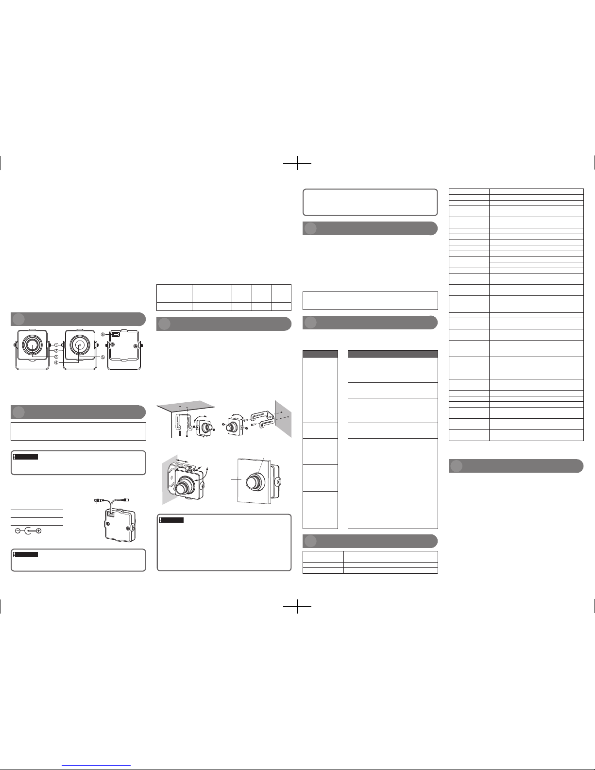
1
Bracket fixing screw (accessory) 2 Mount bracket (accessory)
3
Wide-angle lens
4
Pinhole lens
5
Pinhole lens fixing screw
6
Power cable/Video cable socket
WV-CF132N1E WV-CF132T1E
Major Operating Controls
Installing the Camera
Install the camera with the power of each device turned off.
a Use two mounting screws (M2) (locally procured) to fix the mount bracket
(accessory).
b Use two bracket fixing screws (accessory) to fix the camera onto the
mount bracket (accessory). (Note that the image direction is correct
when the gap is at the lower side)
c Insert the power cable/video cable (accessory) in the socket on the back.
Mounting method for this product
■ Horizontal mounting
■ Open hole mounting
■ Top mounting
■ Side mounting
Hole > ø23
Panel
Installation
Gap
Keep the camera cable far away from the lighting cable
Otherwise noise points may occur.
Radio disturbance
When this product is used near TV/radio antennas, strong electric fields or
magnetic fields (near a motor, a transformer or a power line), images may
be distorted and noise may be produced.
In this case, install a s pecial shie lding pipe and run the camera cable
through it.
Procure fixing screws separately.
The screws to be used are not provided. Prepare screws according to the
material or structure of the installation area and the total weight.
Screw tightening
• The screws and bolts must be tightened with an appropriate tightening
torque according to the material and strength of the installation area.
• Do not use an impact driver. Use of an impact driver may damage the
screws or cause tightening excessively.
• When a screw is tightened, make the screw at a right angle to the surface.
After tightening the screws or bolts, perform a visual check to ensure tightening is sufficient and there is no backlash.
Connecting the power cable
When connecting the power cable, use a connector designed for connecting power cables, and be careful to prevent the power cable from falling off
from the connector.
Power cable diameter and resistance
12 V DC
Use the following formula to calculate the power cable diameter and power
supply.
The voltage applied to the camera should be in the range of DC 10.8 V and
DC 16 V.
DC 10.8 V ≤ V
A
- 2 (R x I x L) ≤ DC 16 V
L: Power cable length (m)
V
A
: DC output voltage of the power supply
R: Copper wire resistance (Ω/m)
I: DC current consumption (A) See the specifications for details.
Copper wire resistance [at 20 °C]
Wire diameter
(AWG)
#24
(0.205
mm
2
)
#22
(0.325
mm2)
#20
(0.519
mm2)
#18
(0.833
mm2)
#16
(1.307
mm2)
Resistance (Ω/m) 0.083 0.052 0.033 0.020 0.013
Video output
terminal
Power plug
(DC terminal ø5.5×2.1)
• The pull-out capacity of a single screw at the installation site is above
50 N {5 kgf}.
• If a site such as a plaster board is too weak to support the total weight,
the installation position shall be sufficiently reinforced.
Scanning area 4.8 mm (H) × 3.6 mm (V)
Scanning system Interlaced scanning 2:1
Scanning line 625 line
Horizontal scanning
frequency
15.625 kHz
Vertical scanning
frequency
50.00 Hz
Synchronous mode Internal synchronization (INT)
Horizontal resolution 650TV line
Vertical resolution 400TV line
Monitor output 1.0 V [p-p] PAL composite video signal 75 Ω
Noise-signal ratio 52 dB (gain control off and weighting on)
Minimum illumination
0.04 lx (F1.2 equivalence) (color mode)
0.02 lx (F1.2 equivalence) (black and white mode)
Lens Fixed iris lens
Focal length
3.6 mm (WV-CF132N1E)
3.7 mm (WV-CF132T1E)
Iris aperture
F2.0 (WV-CF132N1E)
F2.5 (WV-CF132T1E)
Angular field of view
(horizontal/vertical/
opposite angles)
73°/57°/98° (WV-CF132N1E)
77.5°/55°/106° (WV-CF132T1E)
Adjusting angle Tilt angel: 360°
Ambient operating
temperature
–10 °C to +65 °C
Ambient operating
humidity
Less than 90%
Dimensions
(length/width/height)
(excluding the lens)
40 mm × 40 mm × 24 mm (WV-CF132N1E)
40 mm
×
40 mm × 18 mm (WV-CF132T1E)
Light control mode
setting
ELC
Weight (excluding
the mount bracket)
38 g (WV-CF132N1E)
35.5 g (WV-CF132T1E)
Back light
compensation
ON
Auto gain control ON
White balance AUTO
Sensitivity up AUTO
Lens distortion
correction
ON
Digital noise
reduction
ON
Day & Night
(electrical)
AUTO
* The weight and dimensions are approximate. The specifications may be
changed without a prior notice.
 Loading...