

Panasonic WV-CF112E Operating Instructions Manual
THIS PUBLICATION IS PROVIDED "AS IS" WITHOUT WARRANTY OF ANY KIND, EITHER
EXPRESS OR IMPLIED, INCLUDING BUT NOT LIMITED TO, THE IMPLIED WARRANTIES OF
MERCHANTABILITY, FITNESS FOR ANY PARTICULAR PURPOSE, OR NON-INFRINGEMENT
OF THE THIRD PARTY'S RIGHT.
THIS PUBLICATION COULD INCLUDE TECHNICAL INACCURACIES OR TYPOGRAPHICAL
ERRORS. CHANGES ARE ADDED TO THE INFORMATION HEREIN, AT ANY TIME, FOR THE
IMPROVEMENTS OF THIS PUBLICATION AND/OR THE CORRESPONDING PRODUCT (S).
Limitation of liability
IN NO EVENT SHALL Panasonic System Networks Co., Ltd. BE LIABLE TO ANY PARTY OR
ANY PERSON, EXCEPT FOR REPLACEMENT OR REASONABLE MAINTENANCE OF THE
PRODUCT, FOR THE CASES, INCLUDING BUT NOT LIMITED TO BELOW:
(1) ANY DAMAGE AND LOSS, INCLUDING WITHOUT LIMITATION, DIRECT OR INDIRECT,
SPECIAL, CONSEQUENTIAL OR EXEMPLARY, ARISING OUT OF OR RELATING TO
THE PRODUCT;
(2) PERSONAL INJURY OR ANY DAMAGE CAUSED BY INAPPROPRIATE USE OR
NEGLIGENT OPERATION OF THE USER;
(3) UNAUTHORIZED DISASSEMBLE, REPAIR OR MODIFICATION OF THE PRODUCT BY
THE USER;
(4) INCONVENIENCE OR ANY LOSS ARISING WHEN IMAGES ARE NOT DISPLAYED, DUE
TO ANY REASON OR CAUSE INCLUDING ANY FAILURE OR PROBLEM OF THE
PRODUCT;
(5) ANY PROBLEM, CONSEQUENTIAL INCONVENIENCE, OR LOSS OR DAMAGE,
ARISING OUT OF THE SYSTEM COMBINED BY THE DEVICES OF THIRD PARTY;
(6) ANY CLAIM OR ACTION FOR DAMAGES, BROUGHT BY ANY PERSON OR
ORGANIZATION BEING A PHOTOGENIC SUBJECT, DUE TO VIOLATION OF PRIVACY
WITH THE RESULT OF THAT SURVEILLANCE-CAMERA'S PICTURE, INCLUDING
SAVED DATA, FOR SOME REASON, BECOMES PUBLIC OR IS USED FOR ANY
PURPOSE.
Disclaimer of warranty
Important safety instructions
1) Read these instructions.
2) Keep these instructions.
3) Heed all warnings.
4) Follow all instructions.
5) Do not use this apparatus near water.
6) Clean only with dry cloth.
7) Do not block any ventilation openings. Install in accordance with the manufacturer's
instructions.
8) Do not install near any heat sources such as radiators, heat registers, stoves, or other
apparatus (including amplifiers) that produce heat.
9) Only use attachments/accessories specified by the manufacturer.
10) Use only with the cart, stand, tripod, bracket, or table specified by the
manufacturer, or sold with the apparatus. When a cart is used, use
caution when moving the cart/apparatus combination to avoid injury
from tip-over.
11) Refer all servicing to qualified service personnel. Servicing is required when the apparatus
has been damaged in any way, such as power-supply cord or plug is damaged, liquid
has been spilled or objects have fallen into the apparatus, the apparatus has been
exposed to rain or moisture, does not operate normally, or has been dropped.
Operating Instructions
Color CCTV Camera
Model No. WV-CF112E
Before attempting to connect or operate this product,
please read these instructions carefully and save this manual for future use.
The model number is abbreviated in some descriptions in this manual.
We declare under our sole responsibility that the product to which this declaration relates is in conformity
with the standard or other normative document following the provisions of Directive 2004/108/EC.
WARNING:
• To prevent fi re or electric shock hazard, do not expose this apparatus to rain or
moisture.
• To prevent injury, this apparatus must be securely attached to the fl oor/wall/ceiling in
accordance with the installation instructions.
• The installation shall be carried out in accordance with all applicable installation rules.
• This product has no power switch.
When turning off the power, turn off a Power Supply or remove a power cable.
• The connections should comply with local electrical code.
S3125A
This product is a 1/3-type CCD color CCTV camera. Connection of this product to a video
monitor allows users to use this product as a monitoring camera.
Preface
Introduction of newly developed high-resolution CCD
The introduction of the newly developed CCD with 976 horizontal pixels has led to a horizontal
resolution of as high as 600 TV lines.
High sensitivity achieved because of noise reduction function
Sensitivity at the following minimum illuminations has been accomplished for color images
because of the introduction of low noise circuit design (F1.4): 0.07 lx (black-and-white)
Day/Night conversion function equipped
No setup change is required at night because the image automatically changes from the color
mode to the black-and-white mode at low illuminance.
Main functions
Refer installation work to the dealer.
Installation work requires technique and experiences. Otherwise injury, or damage to this
product may result.
Be sure to consult the dealer.
Do not insert any foreign objects.
This could permanently damage this product.
Turn the power off immediately and contact qualified service personnel for service.
Do not attempt to disassemble or modify this product.
Failure to observe this may cause fire or electric shock.
Consult the dealer for the repair or inspections.
Stop operation immediately when something is wrong with this product.
When smoke goes up from this product or the smell of smoke comes from this product, continued use will result in fire, injury, or damage to the product.
Turn the power off immediately and contact qualified service personnel for service.
Select an installation area that can support the total weight.
Selecting an inappropriate installation surface may cause the product to fall down or topple
over, resulting in injury.
Installation work shall be started after sufficient reinforcement.
Periodic inspections shall be conducted.
Rust on the metal parts or screws may cause the product to fall down resulting in injury or
accidents.
Consult the dealer for the inspections.
This product shall be installed in a vibration-free place.
Failure to observe this may cause screws and bolts to be loosened and consequently to fall
resulting in injury.
Install this product in a location high enough to avoid people and objects from bumping the product.
Failure to observe this may cause a drop resulting in injury or accidents.
Do not strike or give a strong shock to this product.
Failure to observe this may cause injury or fire.
Turn the power off when do wiring of this product.
Failure to observe this may cause electric shock. A short circuit or wrong wiring may cause
fire.
Do not use this product in an atmosphere of fl ammable gases.
Failure to observe this may cause injury by explosion.
Avoid installing this product in locations where it is subject to damage by salt or
corrosive gas.
Otherwise the mounting fixtures will deteriorate, causing the product to fall down and leading
to accidents.
Tighten screws and mounting fi xtures to the specifi ed torque.
Failure to observe this may cause a drop resulting in injury or accidents.
Precautions
[Precautions for use]
This product is designed to be used indoors.
This product is not operable outdoors.
This product has no power switch.
When turning off the power, turn off a circuit breaker.
To keep on using with stable performance
Parts of this product may deteriorate and it may shorten the lifetime of this product when
using in locations subject to high temperatures and high humidity. (Recommended operating
temperature: +35 °C or lower)
Do not expose this product to direct heat sources such as a heater.
Handle this product with care.
Do not drop this product, nor apply shock or vibration to this product.
Failure to observe this may cause trouble.
Do not touch the dome cover with your bare hands.
A dirty dome cover causes deterioration of picture quality.
Noise on monitor
This product is equipped with a super sensitive CCD. Therefore, noise may appear on the
monitor. This phenomenon is not trouble.
Discoloration on the CCD color fi lter
When continuously shooting a bright light source such as a spotlight, the color filter of the
CCD may have deteriorated and it may cause discoloration. Even when changing the fixed
shooting direction after continuously shooting a spotlight for a certain period, the discoloration
may remain.
Do not aim this product at strong light sources.
A light source such as a spot light causes a blooming (light bleeding) or a smear (vertical lines).
Cleaning this product body
Turn the power off when cleaning this product.
Do not use strong abrasive detergent when cleaning this product. Otherwise, it may cause
discoloration.
Synchronous mode setting
Image synchronous mode of this camera indicates internal synchronization (INT) only. Set the
multiplex vertical driver (VD2) as OFF when the camera is connected to the system controller
of the company.
Panasonic assumes no responsibility for injuries or property damage resulting from
failures arising out of improper installation or operation inconsistent with this documentation.
This product is designed to be used indoors.
This product is not operable outdoors.
Do not expose the product to direct sunlight for hours and do not install the product near a
heater or an air conditioner. Otherwise, it may cause deformation, discoloration and malfunction. Keep the product away from water and moisture.
Installing place
Contact your dealer for assistance if you are unsure of an appropriate place in your particular
environment.
Make sure that the installation area is strong enough to hold the product, such as a con-•
crete ceiling.
Install the camera in the foundation area of the architecture or where suffi cient strength is •
assured.
If a ceiling board such as plaster board is too weak to support the total weight, the area •
shall be suffi ciently reinforced.
Avoid installing this product in the following locations.
Location where it may get wet from rain or water splash.•
Locations where a chemical agent is used such as a swimming pool.•
Locations subject to steam and oil smoke such as a kitchen.•
Locations near fl ammable gas or vapor.•
Locations where radiation or x-ray emissions are produced.•
Locations where corrosive gas is produced, Locations where it may be damaged by briny •
air such as seashores.
Locations where the temperature is not within –10 °C to +50 °C.•
Locations subject to vibrations (This product is not designed for on-vehicle use.)•
Locations subject to condensation as the result of severe changes in temperature (In case •
of installing the product in such locations, the dome cover may become foggy or condensation may be caused on the cover.)
Avoid moist or dusty places to install this system.
Otherwise, lifetime of the internal parts may be shortened.
Avoid installing this product in a place with a high level of noise.
Installation near an air conditioner, an air cleaner, a vending machine, or the like causes noise.
Avoid installing and connecting during a lightning storm. Otherwise, an electric
shock or fi re may be caused.
Be sure to remove this product if it is not in use.
Do not damage the power plug or cable.
Keep the camera cable away from the lighting cable.
Failure to observe this may cause noise.
Precautions for installation
Smear
Bright subject
Blooming
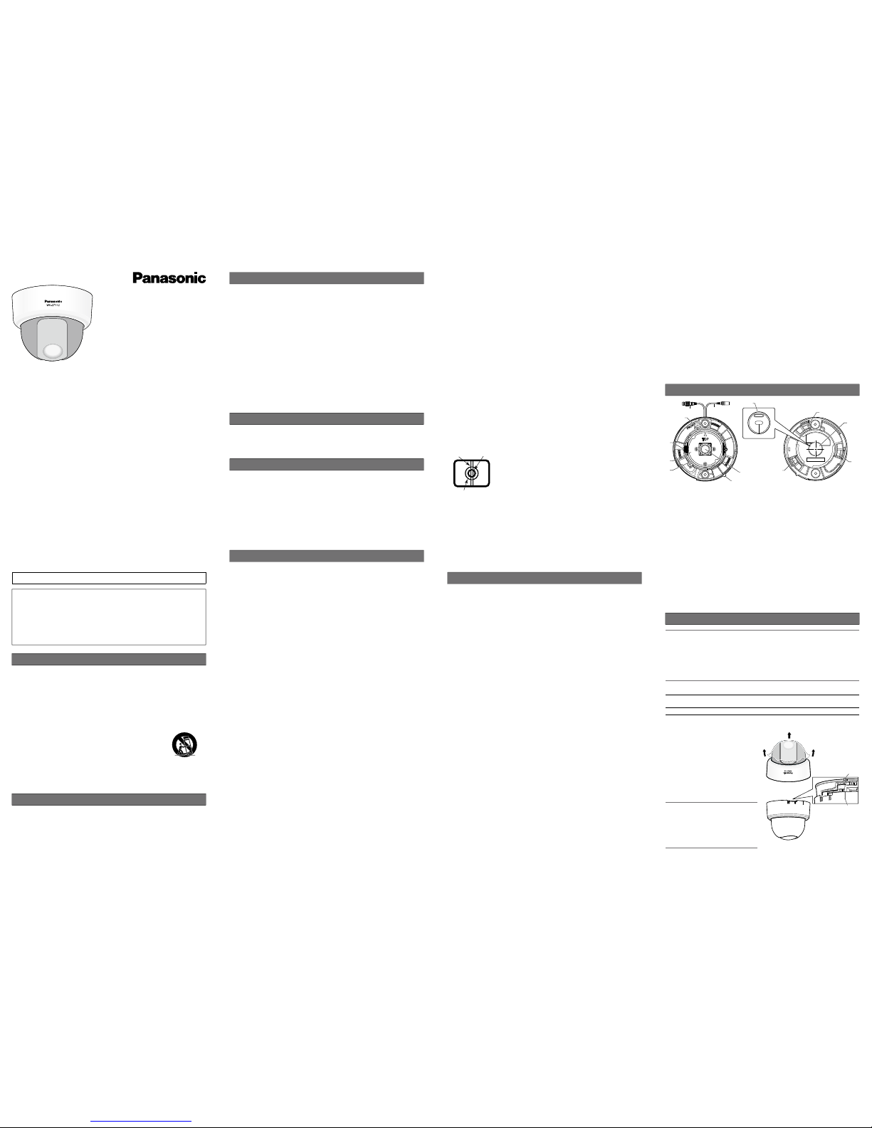
q Video output connector
Transmits composite video signals.
w Mark
This mark is used when the dome cover is installed.
e Lens
r Tilting lock screw
Fixes the tilting position.
t Panning table lock screw [LOCK]
Locks the panning position after adjustment.
y Tilting table
Adjusts the tilting position of the camera.
u Panning table
Adjusts the panning position of the camera.
i Cable access hole
o Power cord
Supplies 12 V DC from an external power source.
!0 Dust guard cap
A rubber cap which prevent dust go into the camera through the cable access hole.
!1 Fingerplate
This is where to put your fingers when removing the dome cover.
Major operating controls and their functions
q
o
t
r
y
u
w
e
!1
!0
i
!1
!1
LOCK
LOCK
Important:
Procure 2 screws (M4) to secure the camera to a ceiling according to the material of the •
installation area. Do not use wood screws and nails. For mounting a camera on a concrete ceiling, use an anchor bolt (M4) for securing.
(Recommended tightening torque M4: 1.6 N·m)
Required pull-out strength of a single screw/bolt is 196 N or more.•
If a ceiling board such as plaster board is too weak to support the total weight, the instal-•
lation area shall be suffi ciently reinforced.
The protection sheet attached to the dome section should be peeled off after installation.•
The mounting conditions of the camera are described as follows:
Installation
place
Applicable mount
bracket
Recommended
screw
Number of
screw
Minimum pull-out
strength (per 1 pc.)
Ceiling (Direct mounting) M4 2 pcs. 196 N
Preparations
■ Remove the dome cover
q Peel off the protection sheet from the
dome cover. Don't remove completely
as this protects the dome during installation.
w Adjust the mark on this camera to [ || ]
on the dome cover, and lift up the dome
cover for approx. 10 mm. Then, turn the
dome cover counterclockwise to align
the mark on the camera to [ | ] on the
dome cover as shown in the illustration.
The dome cover can be removed from
the camera on this position.
Note:
The clear dome cover and the • dome
cover are joined into a single unit.
Therefore, never try to remove them.
Do not try to remove the dome cover •
forcibly on the [ || ] position. Remove the
dome cover after turning it to the [ | ]
position.
Mark
Mark [ | ]
Panasonic Corporation
http://panasonic.net
Panasonic Systems Asia Pacific
2 Jalan Kilang Barat, Panasonic Building, Singapore 159346
Panasonic India Pvt. Ltd.
5th Floor, ABW Tower, Near IFFCO Chowk, Sector-25, Gurgaon, Haryana, 122001, India
Importer's name and address to follow EU rules:
Panasonic Testing Centre
Panasonic Marketing Europe GmbH
Winsbergring 15, 22525 Hamburg F.R.Germany
© Panasonic System Networks Co., Ltd. 2012
Ns0512-0 PGQX1196ZA Printed in China
Radio interference
When the camera is used near TV/radio antenna, strong electric field or magnetic field (near a
motor or a transformer), images may be distorted and noise sound may be produced.
In such a case, run the camera cable through specialized steel conduit tubes.
Locally procure the screws
Screws are not supplied with this product.
Prepare the screws according to the material, structure, strength and other factors of the
mounting area and the total weight of objects to be mounted.
Screw tightening
The screws and bolts must be tightened with an appropriate tightening torque according •
to the material and strength of the installation area.
Do not use an impact driver. Failure to observe this may cause overtightening and conse-•
quently damage to the screws.
When a screw is tightened, make the screw at a right angle to the surface. After tighten-•
ing the screws or bolts, perform visual check to ensure tightening is enough and there is
no backlash.
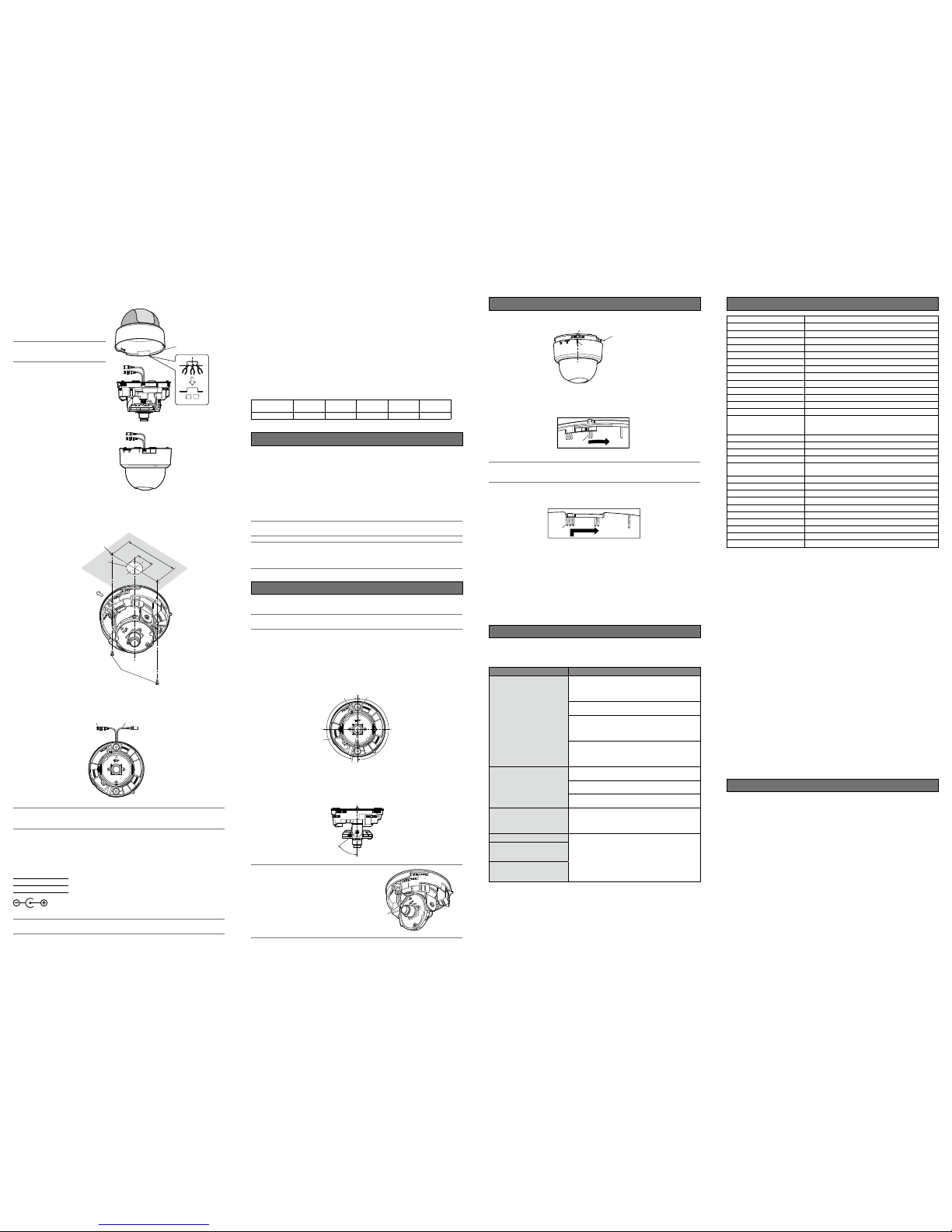
■ About the side cable access hole
If you choose not to drill hole in the ceiling, but to wire the camera with the
cable exposed, cut the cable access
hole on the side of the dome cover to
provide a cable entry.
Note:
Cut out the part as show in the illus-•
tration.
Precautions when wiring from the side:
Move the cable to one side as shown.•
Be careful not to pinch the cable with •
the dome cover.
Installing the camera directly on a ceiling
83.5 mm
15 mm
Recommended screw
(M4, 2 pcs.)
Cable mounting
hole in ceiling
Screws
(M4, locally procured)
LOCK
Front
Installation of camera
Turn off the power of all related devices before installation.
z Remove the camera dome cover.
x Connect all cables.
If necessary, bind the cable with cable tie (locally procured).
c Install the camera.
Mount the camera with 2 screws (M4, locally procured).
Important:
Be sure to avoid twisting the cables when tightening the screws.•
Note:
When attached to the ceiling:•
Install the camera with its front (Model number indication face) facing the same direction
as the “gFRONT” arrow of the installation mark.
Installation
■ Pan and tilt adjustment
Important:
When adjusting pan or tilt, do not hold the lens of the camera.•
q Adjustment of panning position
Loosen the panning table lock screw and rotate the table to determine the
panning position (adjustable range: 350°).
The panning position can be adjusted between +180° (clockwise) and –170° (counter-•
clockwise).
After the panning position is determined, fix the panning table with the panning table lock •
screw.
(Recommended torque: 0.59 N·m)
w Adjustment of tilting position
Turn the tilting table to adjust the tilting position of the camera. (adjustable
range: +75 °)
After the tilting position is determined, fix the tilting table with the tilting lock screw.•
Tighten the tilting lock screw after adjustment. (Recommended torque: 0.• 59 N·m)
Note:
The• image top mark is facing
“ΔTOP” to display the image.
Adjustment
Counterclockwise: –170 º
Panning
table
Clockwise: +180 º
Original position mark
Panning table
lock screw [LOCK]
LOCK
LOCK
Adjustable range:
+75 º, 0 º
Image top mark
LOCK
■ Connections
Connect the coaxial cable (locally procured)
Important:
Be sure to turn off the power of each device before connecting.•
Be sure to secure the coaxial cable connectors.•
Connect a coaxial cable to the video output connector.
Connect the power supply
Connect the two-color conductor cable of the camera to the power supply. The colors and
functions of the conductors are shown below.
Color 12 V DC
Red Positive
Black Negative
Important:
The power supply of 12 V DC shall be insulated against 220 to 240 V AC.•
Power cord
(DC INLINE JACK PLUG
TYPE: ø5.5×2.1)
Video output
connector
LOCK
LOCK
Use a pen to mark the positions of the screws and cable mounting hole in the ceiling.
Attach the camera with 2 screws (M4, locally procured).
z Align the mark with [ | ] on the dome cover, and then install the dome cover.
x Adjust the orientation of the dome cover.
Turn the dome cover clockwise until the mark aligns with [ || ] and a click is heard.
Turn the dome cover to the left or right while viewing the monitor so that the light is not
blocked.
Important:
Be sure to align the mark with [ • || ] when adjusting the dome cover. Do not apply exces-
sive force, or you may cause damage.
c Lift up the dome cover and then turn it clockwise until the mark aligns with [ ||| ]
and a click is heard.
v After finishing the installation, completely peel off the protection sheet that had
been retained on the camera.
Attaching the dome cover
Mark
Mark [ | ]
Opening
(approx. 10 mm)
Mark [ || ]
Mark [ ||| ]
Before asking for repairs, confirm the causes with the following table.
Contact your dealer if a problem cannot be solved even after checking and trying the solution
in the table or a problem is not described below.
Symptom Cause/solution
No image displayed Are the power cord and coaxial cable connected •
appropriately?
Check whether the connection is appropriately →
established.
Is the adjustment monitor connected?•
Confirm whether the monitor is connected. →
Is the monitor brightness appropriately adjusted, or is •
the contrast appropriately adjusted?
Check whether the monitor settings are → appro-
priate.
Is the cushioning material in the spherical cover •
removed?
Confirm whether the cushioning material has →
been removed.
Blurred image Is the spherical cover dirty or damaged?•
Verify the state of the spherical cover. →
Is the focus adjusted correctly?•
Check if the focus is adjusted correctly. →
Is the lens of the camera soiled with dirt or dust?•
Check whether the lens of the camera is clean. →
Black line in image Is the connected system controller set to multiplexed •
vertical drive (VD2)?
Check whether the connected system controller →
is set correctly.
Damaged power cord sheathing
The power cord or connector is damaged. •
Continuous use of the damaged cord or connector
may cause electric shock or fire.
Turn off the power supply immediately and request
repair from your dealer.
Heated portion of power line consisting of power cord and connector during use
The temperature of power cord
rises or falls when the power cord
is bent or stretched during use
Troubleshooting
Power source 12 V DC
Power consumption 12 V DC: 120 mA
Image sensor 1/3-type interline transfer CCD
Effective pixels 976 (H)×582 (V)
Scanning area 4.8 mm (H)×3.6 mm (V)
Scanning system 2:1 interlace
Scanning line 625 lines
Horizontal scanning frequency 15.625 kHz
Vertical scanning frequency 50.00 Hz
Synchronization Internal (INT)
Horizontal resolution 600 TV lines
Vertical resolution 400 TV lines
Video output 1.0 V [p-p] PAL composite video signal 75 Ω
Signal-to-noise ratio 52 dB (AGC OFF)
Minimum illumination 0.08 lx (color mode) at F1.4
0.07 lx (black-and-white mode) at F1.4
* corresponding value
Lens Fixed Lens
Focal length 3.6 mm
Aperture ratio F1.8
View angle 77 ° (H) × 57 ° (V)
Adjustable angle range Pan: +180 ° to –170 °
Tilt: +75 ° to 0 °
Ambient operating temperature –10 °C to +50 °C
Ambient operating humidity Less than 90 %
Dimensions ø108 mm × 88 mm (H)
Mass
200 g
Light control mode ELC (Auto IRIS)
Auto black stretch (ABS) ON
Auto gain control ON
White balance ATW
Digital noise reduction ON
Day & Night (Electric) AUTO
Values of weight and dimensions are approximate. The specification is subject to change *
without notice.
Auto black stretch [ABS]
The latest digital signal technology is applied to automatically detect the dark areas in the
image, acquire the brightness data around the dark areas, and perform real-time color adjustment by calculating the best correction curve for each area. This function can be used to perform real-time adjustment and correction of back light and dark area, and reproduce natural,
clear images.
Auto gain control [AGC]
Automatically increases the gain to make the screen brighter when the illuminance of the subject becomes darker.
Auto tracking white balance [ATW]
Activates the automatic color temperature tracking mode.
The camera continuously check the color temperature of the light source and automatically
adjusts the white balance. The adjustment of the color temperature ranges from approx. 2700
K to 6000 K.
Digital noise reduction [DNR]
The digital noise reduction function reduces noise automatically under the condition of low illuminance.
Day & Night (Electric) [D&N (ELE)]
Automatically switches between color and black-and-white images in accordance with the illuminance.
Switches to black-and-white images when the illuminance around the camera is lower than
approx. 0.07 lx at F1.4 *corresponding value
To obtain color images, a sufficient level of illuminance (approx. 3.0 lx at F1.4 *corresponding
value) is required.
The switching illuminances described above are reference values. The switching illuminance
shall be decided based on the actual installation environment.
There may be repeated switching between color and black-and-white images depending on
the setting and environment.
Specifications
Operating Instructions (this document) ......... 1 pc.
Standard accessories
Connection of power cord
When connecting the power cord, use connectors that are designed for the power cord, and
be careful not to let the power cord fall off.
In addition, waterproofing work is needed at the joint, e.g., wrapping waterproof tape around
the joint.
Cable length and wire gauge
12 V DC
Calculation of the relation among the cable length, resistance, and power supply.
The voltage supplied to the camera shall be between 10.8 V DC and 16 V DC.
10.8 V DC ≤ VA - 2 (R x I x L) ≤ 16 V DC
L : Cable length (m)
R : Resistance of copper wire (Ω/m)
VA : DC output voltage of power supply unit
I : DC current consumption (A)
See specifications.
Resistance of copper wire [at 20 °C]
Copper wire size
(AWG)
#24
(0.205 mm
2
)
#22
(0.325 mm2)
#20
(0.519 mm2)
#18
(0.833 mm2)
#16
(1.307 mm2)
Resistance Ω/m 0.083 0.052 0.033 0.020 0.013
Side cable access hole
 Loading...