

Page 1
Operating
Instructions
Remote Control Box
WV-CB700A
Panasonic.
Befoie attempting to connect Of operate this product,
please read these mtfwctiorvs completely.
Page 2

...........................................................................................................................................For U.S.A
CAUTION
A
CAUTION:
TO REDUCE THE RISK OF ELECTRIC SHOCK, DO
NOT REMOVE COVER (OR BACK). NO USER SER
VICEABLE PARTS INSIDE.
REFER SERVICING TO QUALIFIED SERVICE
PERSONNEL.
The lightning flash with arrowhead
symbol, within an equilateral triangle,
is intended to alert the user to the
presence of uninsulated "dangerous
voltage" within the product's
A
SA 1965
SA 1966
WARNING:
TO PREVENT FIRE OR SHOCK HAZARD, DO NOT EXPOSE THIS APPLIANCE TO RAIN OR MOISTURE.
enclosure that may be of sufficient
magnitude to constitute a risk of elec
tric shock to persons.
The exclamation point within an
equilateral triangle is intended to alert
the user to the presence of important
operating and maintenance (servicing)
instructions in the literature accompa
nying the appliance.
A!
Warning:
This equipment generates and uses radio frequency
energy and if not installed and used properly, i.e., in
strict accordance with the instruction manual, may
cause harmful interference to radio communications.
It has been tested and found to comply with the limits
for a Class A computing device pursuant to Subpart
J of Part 15 of FCC Rules, which are designed to pro
vide reasonable protection against such interference
when operated in a commercial environment.
.......................................................................................... For CANADA .
This digital apparatus does not exceed the Class A
limits for radio noise emissions from digital apparatus
set out in the Radio Interference Regulations of the
Canadian Department of Communications.
The serial number of this product may be found on
the bottom of the unit.
You should note the serial number of this unit in the
space provided and retain this book as a permanent
record of your purchase to aid identification in the
event of theft.
Model No.________________________________
Serial No.
________________________________
Page 3

CONTENTS
PREFACE
FEATURES
PRECAUTIONS
MAJOR OPERATING CONTROLS AND THEIR FUNCTIONS
CONNECTIONS
SPECIFICATIONS
ACCESSORY
OPTIONAL ACCESSORIES
2
2
2
3
11
12
13
13
- 1 -
Page 4

PRERVGE
PRECAUTIONS
A Remote Control Box (RGB) WV-CB700A is used to
remotely control either the Color Camera WV-F700 or
WV-F500 series for ENG/EFP operation.
Features and functions include white balance setting,
iris control, R/B gain control total pedestal control,
color bar/camera selection switch, horizonrtal and
subcarrier phase adjustment for gen-lock and intercom
level control.
FEARURES
1. The video signal, gen-lock and the camera control
from the RGB are available by using the optional
RGB cable.
2. Color adjustment can be made by the R and B gain
controls.
3. With lens iris control, the auto iris level of zoom lens
on the camera can be manually controlled from the
RGB.
4. Horizontal and subcarrier phase controls on the
RGB can adjust for matching the phase of the
gen-lock signal for the system use.
Do not attempt to disassemble the unit.
There are no user-serviceable parts inside.
Do refer any servicing to qualified service
personnel.
Do not abuse the unit. Avoid striking, shading etc.
Do not use strong or abrasive detergents when
cleaning the unit. Do use dry cloth to clean the unit
when dirty. In case the dirt is hard to remove, use
mild detergent and wipe gently.
Do not expose the unit to rain or moisture. Do take
immediate action if ever the unit do become wet.
Turn power off and refer servicing to qualified
service personnel. Moisture can damage the unit
and also create the danger of electronic shock.
Use the unit under the conditions where
temperature is within 23®F - 113° (—5°C - +45°C)
and humidity is less than 907..
-2 -
Page 5
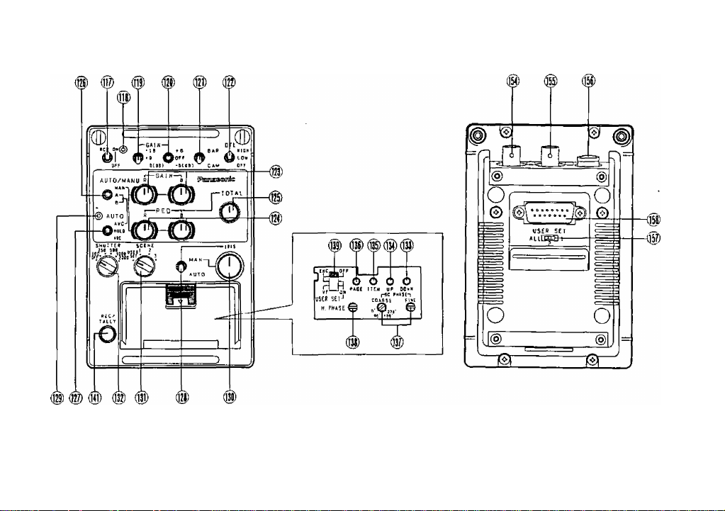
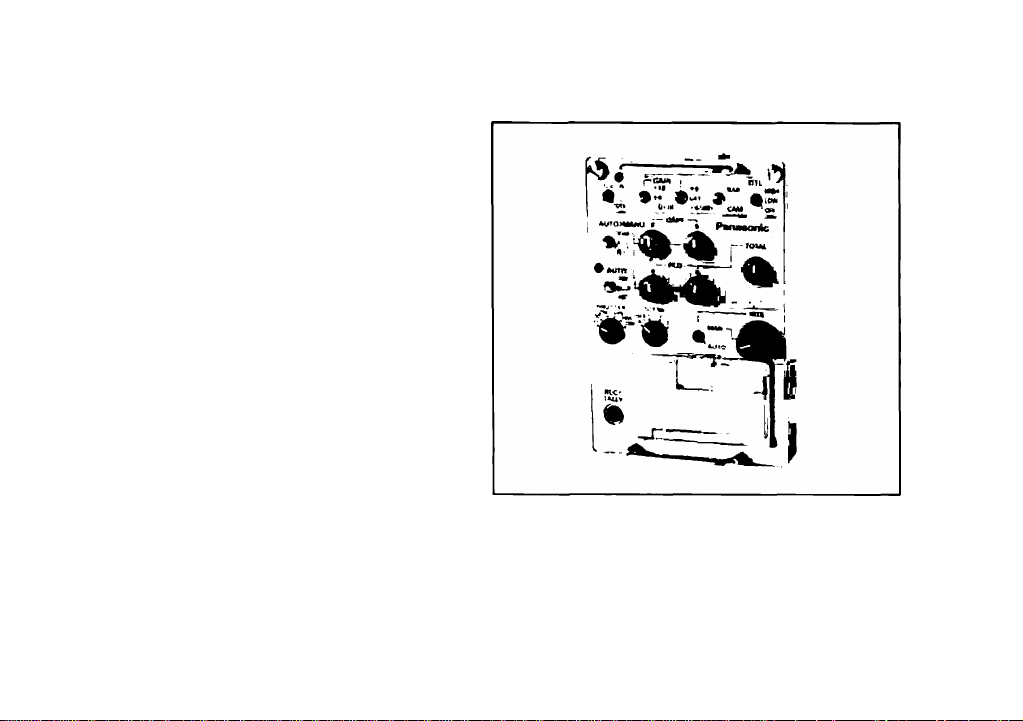
MAJOR OPERATING CONTROLS AND THEIR FUNCTIONS
Note: The numbering of the each item is same as the Operating Instructions of WV-F700 or WV-F500 series.
-3-
Page 6

117. Remote Control Box (RGB) Operation Switch
(RGB)
When connecting the Remote Control Box to the
camera without using the Remote Control Unit, set
this switch to ON position. When the RGB is
installed in the RGB this switch is inoperative.
118. Remote Control Box (RGB) Indicator
(ON/OFF)
This indicator iights while control data is
communicated between the camera and Remote
Control Unit (RCU) or Remote Control Box (RCB).
121. Color Bar/Camera Selection Switch
(BAR/CAM)
In a system configuration, this switch is used for
signal selection between camera mode and color
bar mode.
BAR:
A' color bar signal is provided from the Video
Output Connector on the Remote Control Box
(RCB).
CAM:
The actual picture, as picked up through the
lens, is displayed.
119. High Gain Selection Switch
(0 dB/+9dB/+18dB)
Normally set this switch to the 0 dB position.
Positions +9 dB and +18 dB increase the video
output amplitude for dark scenes and are equivalent
to opening the lens iris 1.5 or 3 F-steps, respectively.
120. 6dB Gain Selection Switch
(+6dB/OFF/-6dB)
Normally set this switch to OFF position. By
the combination of this switch with the High Gain
Selection Switch (119), fine adjustment of the gain
level is available.
122. Detail Level Selection Switch
(DTL, LEVEL-HIGH/LOW/OFF)
The detail/aperture level can be selected by this
switch in three steps. Set this switch to the
desired position while observing the sharpness of
the picture.
123. Red and Blue Gain Controls (R GAIN/B GAIN)
These controls are used to manually adjust the
white balance.
These controls only work when the White/Black
Balance Selection Switch (126) is set to the MANU
position.
-4 -
Page 7

Turn the controls clockwise to increase the red
and blue signal levels, and counterclockwise to
decrease these levels.
Note:
As these controls employ Digital Processing,
the Red and Blue signal levels will be changed
in discrete steps.
124. Red and Blue Pedestal Level Controls
(PED, R/B)
The black balance can be set manually by these
controls when the White/Black Balance Selection
Switch (126) is set to the MANU position. Turn these
controls clockwise to increase the red and blue
pedestal levels, and counterclockwise to decrease
the levels.
Note:
As these controls employ the Digital
Processing, these levels will be changed in the
steps.
125. Total Pedestal Level Control
(TOTAL PEDESTAL)
This control can adjust the pedestal level of the
video signal (luminance) for matching the black level
between two or more cameras in a system. Turn this
control clockwise to increase the pedestal level,
and counterclockwise to decrease the level.
Note:
As this control employs the Digital Processing,
this level may be changed in the step.
126. White/Black Balance Selection Switch
(AUTO/MANU,MAN/A/B)
This switch is used to select the white balance and
black balance modes as follows:
MAN:
The white balance and black balance can be
adjusted by the Red and Blue Gain Controls
(123) and the Red and Blue Pedestal Level
Controls (124).
A: The White Balance can be set automatically by
pressing the Auto White/Auto Black Set Switch
(127) upwards, The setting is stored in memory
A.
B: Similar to A, but the setting is stored in memory
B.
Note:
Two white balance setting, one each for
different lighting conditions such as indoor and
outdoor, may be stored in the two memories, A
and B.
- 5 -
Page 8

127. Auto White/Auto Black Set Switch
(AWC/HOLD/ABC)
This switch sets the white balance and black
balance automatically as foNows;
AWC:
This position is used for setting the white
balance when the White/Black Balance
Selection Switch (126) is set to the A or B
position of the White/Black Balance Selection
Switch. White balance adjustment is required
when "AWC A NG" or "AWC B NG" is displayed
in the viewfinder or when the Auto Warning
Indicator (129) on tights.
HOLD:
In this position, the white and black balances
set at the AWC or ABC position can be held
fixed, if so desired, for at least one year.
ABC:
This position is used for setting the black
balance when the White/Black Balance
Selection Switch (126) is set to the A or B
position. Black balance adjustment is required
when "ABC NG" is displayed in the viewfinder
or when the Auto Warning Indicator (129) on
the Remote Control Box (RGB) lights.
Note:
Since the black balance adjustment is always
automatically performed the picture wilt flash in
the viewfinder and on the monitor screen while
the black balance is being set. This flashing
indicates that the adjustment is currently being
performed and will cease once the adjustment
is completed.
128. Lens Iris Selection Switch (IRIS, MAN/AUTO)
This switch is used to set the lens iris of the auto
iris servo control zoom lens as follows.
Auto:
The iris level of the lens is controlled
automatically.
Note:
Be sure to set the Iris Control Selection Switch
on the zoom lens to the AUTO posiiton.
MAN:
The iris level of the lens is controlled to the
desired level by using the Lens iris Control (130).
-6-
Page 9

129. Auto Warning Indicator (AUTO)
This indicator blinks while the white balance or
black balance is being automatically set. It goes
out once the white and black balances have been
correctly set.
This indicator lights when the white or black balance
is set improperly. In this case, carry out the
automatic setting procedure for white and/or black
balance.
130. Lens Iris Control (IRIS)
The iris level of the zoom lens can be manually
controlled by turning this control when the Lens Iris
Selection Switch (128) is set to the MAN position.
131. Scene Selection Switch (SCENE)
This switch is used to select the most suitable
camera conditions, depending on scene conditions,
to obtain the best picture possible,
Refer to the Operating Instructions of the Color
Camera WV-F700 or WV-F500 series.
132. Electronic Shutter Speed Selection Switch
(OFF/100/250/500/1000/2000)
This switch is operative only when a camera
featuring the electronic shutter is connected with
this control box.
When fast-moving objects are shot at the slow
shutter speeds typically found in conventional
cameras they will appear blurred. The camera,
however, features an electronic shutter function
from which the following speeds can be selected:
1/100,1/250,1/500.1/1000 or 1/2000 of a second.
As a result, blur-free recording of high-speed action,
such as car racing, golf swings, gymnastics, birds in
flight is possible.
The selection of shutter speed is made by pressing
this switch.
OFF:
Set this switch to this position when recording
normally with standard shutter speeds.
1/100,1/250,1/500,1/1000,1/2000;
Choose the suitable shutter speed from these.
133. Down Switch (DOWN)
This switch is used to decrease the set value in the
item pointed out by the cursor.
134. Up Switch (UP)
This switch is used to increase the set value in the
desired item pointed out by the cursor.
- 7 -
Page 10

135. Item Switch (ITEM)
This switch is used to choose the item in the set-up
menus.
136. Page Switch (PAGE)
This switch is used to choose the desired set-up
menu from the four menus,
137. Subcarrier Phase Coarse and Fine Controls
(SC PHASE COARSE/FINE)
These controls allow for adjustment of the camera
signal subcarrier phase from 0° to 360°, to match
the phase with that of the burst signal at the
Gen-lock Input Connector on the RCU in a system
configuration.
The COARSE control adjusts the subcarrier phase
from 0° to 360° in 90° steps, while the FINE control
allows for continuous fine adjustment over a range
of 90°
138, Horizontal Phase Control for Gen-lock
(H PHASE)
The horizontal phase of the camera signal can be
adjusted to match the horizontal phase of the signal
at the Gen-lock Input Connector on the RCU.
139. ENC/VF Selection Switch (ENC/VF, OFF/ON)
This switch selects Encoder output or EVF (black
and white) output from the Video Output Connector
and whether the User Set Function is available as
follows:
1. Switch set to position #1:
Encoder is output from
Connector on the RCB
Video Output
the
and
the User Set
function is not available.
2. Switch set to position #2:
Encoder is output from
Connector on the RCB
the
Video Output
and
the User Set
function is available,
3. Switch set to position #3;
EVF (black and white) signal is output from the
Video Output Connector on the RCB, User Set
function is available and the User Set menu is
displayed on the monitor.
-8-
Page 11

141. Tally Indicator (REC/TALLY)
When the Remote Control Box (RGB) is used in
conjuction with a Special Effects Generator, the
Tally Indicator inside the viewfinder as well as this
indicator on the Remote Control Box (RGB) will tight
to indicate that recording is in progress.
Note:
When using the Remote Control Box (RGB) in
the Remote Control Unit (RCU), the recording
start/stop function is not available.
154, Monitor Output Connector
As this connector is in parallel connection with
the VIDEO 2 OUTPUT Connector on the RCU,
do not output the signal simultaneously from both
connectors.
155. Gen-lock Input Connector of Remote Control
Box
This connector is used to Input the gen-lock signal
to this control box when using the Remote Control
Box extended from the Remote Control Unit.
156. Remote Control Unit Extension Connector
This connector is used to extend this control
box from the Remote Control Unit or from
the camera by using the optional RGB cable
(WV-CA10825/WV-CA10B50).
The maximum cable length for the extension is 300 ft
(100m),
Refer to the following table.
Cable length
Decrement
(ft)
(m) 2
6 75
25
10'/. ^5'/.
150 300
50 100
207. 307.
Note:
As the video level is changed by using various
cable lengths, under certain conditions it may
be out of the specification for the WV-F700 or
WV-F500 series.
167. Remote Control Unit Connector
This connector is used for directly connecting with
the Remote Control Box Connector on the Remote
Control Unit
- 9 -
Page 12

158. User Set Switch (USER SET)
By setting this switch when the Scene Selection
Switch (131) is set to the USER SET position, the
page selection of the set up menus is available as
follows.
All:
All the pages (pagel -page4) in the set up menu
are displayed by setting this switch to this
position.
1: Page 1 and 2 are displayed by setting this
switch to this position.
2: Only Page 3 is displayed by setting this switch
to this position.
Refer to "THE USER SETTING OPERATION'
on Operating Instructions of the Color Camra
WV-F700 or WV-F500 series.
-10-
Page 13

CONNECTIONS
Connection with the Camera
Connect the Remote Control Box Connector on the
Camera Head to the Remote Control Unit Extension
Connector (156) on the Remote Control Box by
using the optional RGB Cable WV-CA10B25 or
WV-CA10B50.
Note;
In the following system connection, the video
signal from the Monitor Output Connector on
the Camera Head has priority of the video
signal over the Monitor Output Connector (154)
on the Remote Control Box, so the picture is
not displayed on the monitor connected to the
Remote Control Box.
The decrement of the video signal for the cable
length is shown in the following.
The cable length
2 m:
25 m:
50 m:
100 m:
Decrement
Approx. \0%
Approx, 15*/.
Approx. 20*/.
Approx. 30'/
OPERATING PROCEDURE
Refer to the Operating Instructions of the Color Camera WV-F700 or WV-F500 Series for details.
- 11 -
Page 14

SPECIFICATIONS
Video Output :
Gen-lock Input :
1.0 Vp-p NTSC composite/75 ohms x 1 (BNC connectors)
1.0 Vp-p NTSC composite or black burst signal/75 ohms x 1 {at camera
head operating)
(BNC connectors)
Intercom Jack :
Maximum Cable Length
M-6
Approx. 80 ft (25m) with the optional RGB Cable WV-CA10B25.
Approx, 160 ft (50m) with the optional RGB Cable WC-CA10B50.
Switches :
RGB Operation, High Gain Selection, 6 dB Gain Selection,
Color Bar/Camera Selection, Detail Level Selection,
White/Black Balance Selection, Auto White/Auto Black Set,
Lens iris Selection, Scene Selection, Eiectronic Shutter Speed Selection,
Down, Up, Item, Page, ENC/VF Selection, User Set Switch
Controls :
Red and Blue Gain, Red and Blue Pedestal Level, Total Pedestal Level,
Lens Iris, Subcarrier Phase Corse and Fine, Horizontal Phase for Gen-lock
Ambient Operating Temperature
Ambient Operating Humidity :
Dimensions :
23®F- 113°F(-5°C--F45°C)
Less than 90 *A
3-9/16"(W) X 5-3/16"(H) X 2'’(D)
90(W) X 131(H) X 51.5(D) mm
Weights :
0.8 lbs (0.37 kg)
Weight and dimensions shown are approximate.
Specifications are subject to change without notice.
-12-
Page 15

ACCESSORY
RGB Cable (Approx. 7 ft (2m)) 1 pc.
OPTIONAL ACCESSORIES
Color Camera
Remote Control Unit
RGB Cable
....................
........................
WV-F700 or WV-F500 series
.....................................
WV-CAi0B25/WV-CA10B50
WV-RC700A
- 13 -
Page 16

Panasonic
Broadcast & Television Systerrvs Company
Division of Matsushita Electric Corporation of America
Executive Office One Panasonic Way Secaucus NJ 07094
For further information on our complete line of
Broadcast and Television Systems products
please call 1 1800) 524 0864 for your nearest
Panasonic regional sales office
MATSUSHITA ELECTRIC OF CANADA UMITED
5770 Ambler Drive Mississauga Ontario Canada L4W 2T3 (416)624-5010
PANASONIC SALES COMPANY
DIVISION OF MATSUSHITA ELECTRIC OF PUERTO RICO, INC
San Gabriel Industrial Park 65th Infantry Ave KM OSCarolma Puerto Rico 00630 (809)750 4300
N0393-0 YWV8QA3032AN Printed in Japan
® 13
 Loading...