

Panasonic WV-BS504 User Manual

Operating
In^ructions
Combination Camera
WV-BS504
WV-BST504
( < i' j a V. 4'r n.“
WV-CS604A
WV-CSR604
WV-CST604
Panasonic
::i:crn|iii'i.j l<><:oniitti:l :>i :4ic'i]lir H‘S 0tOOu&l. Cl«aS6 r«aa r63« ■‘3UUC1iv<’S CC<rp 91« y

CAUTION
RISK OF ELECTRIC SHOCK
A
CAUTION:
TO REDUCE THE RISK OF ELECTRIC SHOCK. DO
NOT REMOVE COVER (OR BACK). NO USER SER
VICEABLE PARTS INSIDE.
REFER SERVICING TO QUALIFIED SERVICE
PERSONNEL.
A
SA 1965
SA 1966
WARNING:
TO PREVENT FIRE OR ELECTRIC SHOCK HAZARD, DO NOT EXPOSE THIS APPLIANCE TO RAIN OR MOISTURE.
DO NOT OREN
The lightning Hash with arrowhead
symbol, within an equilateral triangle,
is intended to alert the user to the
presence of uninsulated "dangerous
voltage" within the product's
enclosure that may be of sufficient
magnitude to constitute a risk of
electric shock to persons.
The exclamation point within an
equilateral triangle is intended to alert
the user to the presence of important
operating and maintenance (servic
ing) instructions in the literature
accompanying the appliance.
A
.................................
Warning;
This equipment generates and uses radio frequency
energy and if not installed and used properly, i,e., in
strict accordance with the instruction manual, may
cause harmful interference to radio communications.
It has been tested and found to comply with the limits
for a Class A computing device pursuant to Subpart J
of Part 15 of FCC Rules, which are designed to
provide reasonable protection against such
interference when operated in a commercial
environment.
The serial number of this product may be found on the
top of the unit.
You should note the serial number of this unit in the
space provided and retain this book as a permanent
record of your purchase to aid identification in the event
of theft.
Model No. ____________________________________
Serial No.
For U.S.A-^

CONTENTS
PREFACE
FEATURES ............■
PRECAUTIONS
CONSTRUCTION
SETUP PROCEDURE
.................................................................
...............................................
..........................................................
........................................................
...................................................
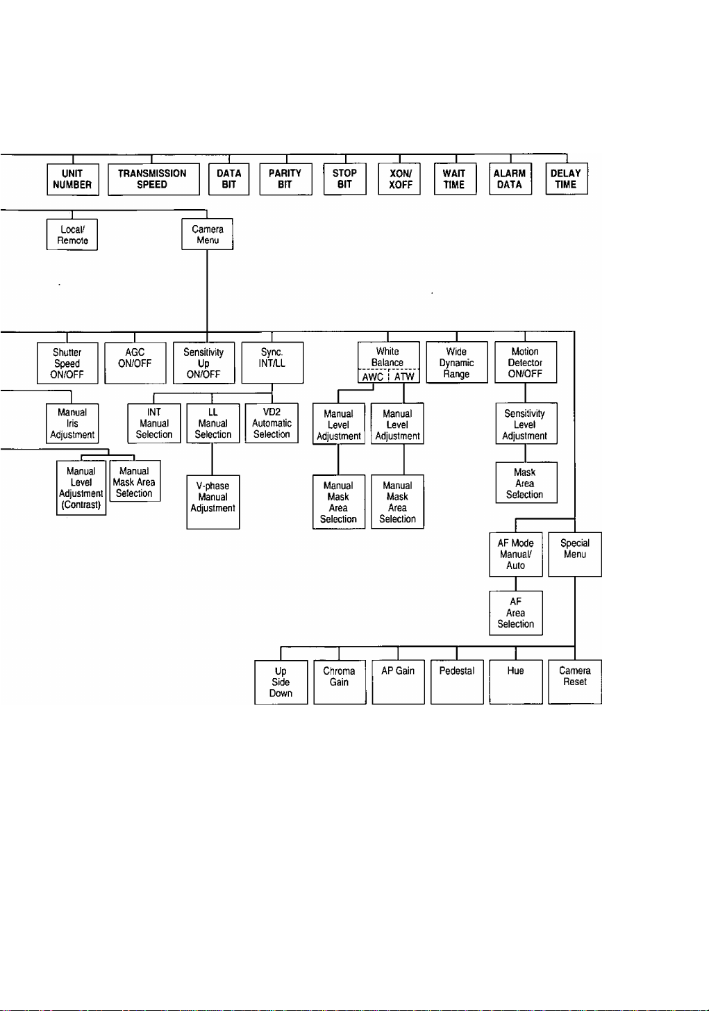
■ Setup Menu ........................................................ 4
■ Setup Menu Description
■ Setting Procedures
■ Menu Display
■ Communication Parameter Setting
.........................................
...............................................
.....................................................
.............................
■ Preset ............................................................. 12
■ Deleting Preset Positions
.......................................
■ Home Position Setting ...........................................16
2
2
2
3
4
6
9
10
10
■ Self Return Setting .....................................................17
■ Auto Mode Setting
.....................................................
17
■ LOCAL/REMOTE Setting ........................................ 18
■ Camera Setting
..........................................................
18
INSTALLATION .......................................................... 29
CONNECTIONS
SYSTEM CONNECTIONS
.........................................................
.............................................
32
34
PREVENTION OF BLOOMING
AND SMEAR
.............................................................
35
SPECIFICATIONS........................................................ 35
ACCESSORIES........................................................... 37
16
OPTIONAL ACCESSORIES
............................................
37
- 1 -

PREFACE
Panasonic presents highly advanced CCVE
technology meets the demand of new and everchanging applications. This model is utilized video
surveillance device that incorporates a Digital signal
Processing (DSP) high-performance camera,
pan/tilt mechanism, 10 times zoom lens and
receiver in its compact enclosure.
The camera portion incorporating a high-sensitivity
CCD provides 480-line horizontal resolution for WVCS604A, WV-CS604, and WV-CST604 (500-line for
WV-BS504 and WV-BST504) and an S/N ratio of 48
dB for WV-CS604A, WV-CST604 and WV-CSR604
(46 dB for WV-BS504 and WV-BST504). With its
advanced digital signal processing circuit, it is
equipped to handle the surveillance tasks of the
coming age.
The pan/tilt portion, allowing 360-degree endless
panning, is designed to meet specific user need.
This model utilized surveillance device offers
cutting-edge technology for advanced video
surveillance.
FEATURES
1. The following functions are built in.
(1) Auto Light Control (ALC)/Manual Override
Iris
(2) Character Generator
(3) Back Light Compensation (Auto; Factory
preset, Manual: Manual photometric
measuring area set)
(4) Auto/Manual White Balance Function
(5) Electronic Shutter Function
2. Minimum illumination of 3 lx (0.3 foot-candle)
for WV-CS604A and WV-CSR604, 6 lx (0.6 footcandle) for WV-CST604, 0,1 lx (0.01 footcandle) for WV-BS504, and 0.2 lx (0,02 footcandle) for WV-BST504.
3. High quality picture;
(a) 2H type vertical enhancer for greater
picture sharpness
Chroma averaging circuit for better color
(b)
signal to noise ratio (available only with
WV-CS604A, WV-CSR604, or WV-CST604 )
Minimum of aliasing on fine objects
(c)
Expanded dynamic range by use of knee
(d)
circuit
Highlight aperture correction for greater
(e)
picture detail of bright objects
4. Back Light Compensation for use under
unusual lighting conditions.
5. Selectable electronic sensitivity enhancing
modes including : AUTO, MANUAL and OFF
6. Built in Digital Motion Detector
7. 64 preset position-position, focus, zoom ratio,
rotation mode, etc.
8. 360-degree endless panning.
9. Maximum 240 degrees/second speed from one
position to the next.
10. There is no distance limit for remote access
with the specified extension unit, (only for WVCSR604) ■
PRECAUTIONS
• Do not attempt to disassemble this unit. There
are no user serviceable parts inside. Refer
servicing to qualified service personnel,
• This unit is designed for indoor use or locations
where it is protected from rain and moisture.
• Be sure to mount on a flat ceiling.
• Do not drop metallic parts through slots. This
could permanently damage this unit. Turn the
power off immediately and refer servicing to
qualified service personnel.
• Wipe the cover regularly with a soft and dry
cloth, or a cloth moistened with a solution of
water and normal kitchen detergent.
Do not use chemicals for cleaning the cover as
it may damage the surface.
• Refer all work related to the installation of this
product to qualified service personnel or
system installers.
• Use this unit in an environment where the
temperature is within -10“C - -h50°C (14°F -
122°F), and the relative humidity within 90%.
• Never aim the camera at bright objects.
Whether the camera is in use or not, never aim
it at the sun, or other extremely bright objects
as this could cause blooming.
• This unit is designed exclusively for ceiling
installation. If installed in standup position, the
picture will be upside down and the pan/tilt
movement will be reversed.
r- CAUTION
To prevent fire or electric shock hazard, the UL
listed wire, VW-1, style 1015, AWG 18 or UL
listed power supply cord, type SJT should be
used for the cable for 24V AC input terminals.
-----------------------------------------------------
-2-

CONSTRUCTION
(1) Data Cable (only for WV-CSR604)
(2) Video Output Connector
(3) Power Cable
(4) Camera Mounting Angle
(5) Panning Start Point
(6) Fail Prevention Wire
(7) Decoration Cover
(8) Cooiing Holes
(9) Dome Cover
-3-
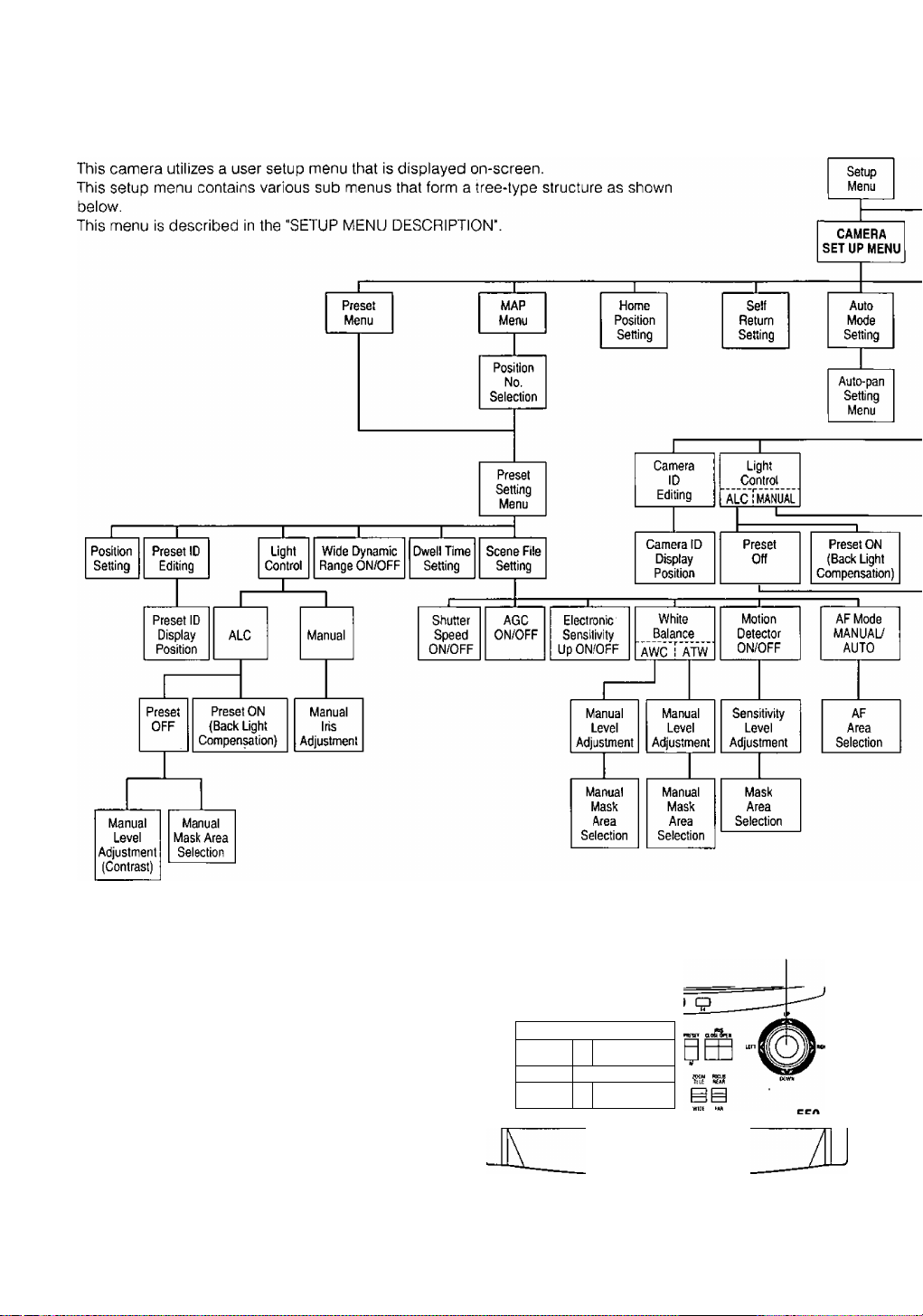
SETUP PROCEDURE
Setup Menu
The above menus should be set with the following
switches.
• WV-CU550A
Joystick:
CAM (SET) Key:
Used to move the Cursor
Upward/Downward/Right/ Left
and select the mode.
Also used to adjust the level.
This key is for setting the mode
and switching between menus.
-4-
a t
rr~| [Z
m r
Joystick
I111ll 2 III 3l
1 [uqn] I [ G ] I [c^j
SytlMTi Con(fOH*< WV'CU UDUa
CAM (SET) Key
Note:
The menus described in
only when WV-CSR604 is used.
bold
are displayed
• WV-RM70
(available with all models except WV-CSR 604)
Up Switch:
Down Switch:
Right Switch:
Moves the cursor upwards.
Moves the cursor downwards.
Moves the cursor right. This
switch also selects the mode
and can be used to adjust
certain Levels.
Left Switch:
Moves the cursor left. This switch
also selects the mode and can
be used to adjust certain Levels.
Set Switch:
This switch is for setting the
mode and switching between
menus.
Left Switch
Set Switch
-5-
Up Switch
Right Switch
■ Down Switch

■ Setup Menu Description
• RS485 site communication (only WV-CSR604)
Communication parameters
• Full/Half duplex (page 29)
• Transmission speed (2400 - 19200 bps) (page 11)
• Parity check, Stop bit, Characters, Flow control (page 11)
• Retransmit time, Delay time. Alarm output (page 11)
• Camera units (96 units max.) (page 29)
• Termination ON/OFF (page 29)
• Reset parameters (page 29)
• PRESET
(1) Position (POSITION SET)
POSITION SET adjusts the camera picture by panning, tilting, zooming and focusing.
See page 12 for the setting.
(2) Preset Identification (PRESET ID)
A preset ID (identification of up to 16 alphanumeric characters) can be displayed on the screen.
See page 13 for the setting.
(3) Light Control (ALC/MANUAL)
ALC/MANUAL refers to the mode of the incoming light level control.
See page 15 for the setting.
(4) Wide-Dynamic Range (WiDE D-RANGE)
WIDE D-RANGE is used to enhance picture viewing. This function is useful, for example, when a picture is
too dark or too bright to watch the object because the lighting conditions are too dim or too bright.
See page 15 for the setting.
(5) Dwell Time (DWELL TIME)
DWELL TIME is the duration that the picture of each camera position is displayed. You can select a preset
duration from the menu.
See page 15 for the setting.
(6) Scene File (SCENE FILE)
SCENE FILE is used to memorize ihe camera shooting scene. You can store up to 10 (scene file No. 1 to
No. 10) camera shooting scenes. The camera functions below are available for detail setting of the scene
files to be stored. These functions are stored in memory together with the scene files.
Camera functions available for detail setting of scene files are: shutter speed, AGC, electronic sensitivity
enhancement, white balance, motion detector and AF mode.
See page 15 for the setting.
• Home Position (HOME POSITION)
HOME POSITION is the camera’s basic position. It returns to this position automatically, when a specified time
has elapsed after a manual operation.
See page 16 for the setting.
• Self Return (SELF RETURN)
SELF RETURN is the time-out parameter for returning to the home position.
See page 17 for the setting.
-6-

• AUTO MODE
AUTO MODE is for setting the movement of the camera. You can select from three automatic operation modes
and one manual operation mode as follows:
OFF mode:
SEQ mode:
SORT mode:
No automatic operation. The camera can be operated only manually.
The camera operates in the sequence of preset positions in numerical order.
The camera operates in the sequence of preset positions counterclockwise from PanЯilt Starting
Point.
AUTO PAN mode:
The camera automatically turns within the preset panning range.
See page 17 for the setting.
•LOCAUREMOTE
LOCAUREMOTE determines the relationship between camera operation and ON/OFF status of the controller.
You can select one of the following two modes:
LOCAL:
REMOTE:
The camera continues operating in auto mode when the controller is turned OFF.
The camera stops operating in auto mode approx. 1 minute after the controller is turned off.
See page 18 for the setting.
• Camera
(1) Camera Identification (CAMERA ID)
You can use the camera identification (CAMERA ID) to assign a name to the camera. The camera ID
consists of up to 16 alphanumeric characters. You can select whether to have the camera ID displayed on
the monitor screen or not.
Note:
See page 19 for the setting.
(2) Light Control (ALC/MANUAL)
You can select the mode for adjusting the lens iris.
The modes are as follows:
ALC:
The lens iris is automatically adjusted according to the brightness of the object.
MANUAL:
The lens iris is fixed at the value you have set regardless of the brightness of the object.
■ Back Light Compensation (BACK LIGHT COMP)
Back light compensation is available in ALC mode. It eliminates interference by strong background lighting
which maxes the camera picture dark, such as a spotlight. You can select one of two modes (PRESET ON
or PRESET OFF) for back light compensation.
This function is disabled in MANUAL mode.
• Factory Setup Mode (PRESET ON)
In normal use the important object in a scene is placed in the center of the monitor’s screen. In the factory
setup mode, more photometric weight is given to the center of the screen (where the important object is
located) than to the edge of the picture (where a bright back light would most likely be located). In this
mode, even though the back light may vary, the object at the center of the screen can still be clearly seen.
Note:
See page 20 for the setting.
•
• Field Setup Mode (PRESET OFF)
This mode is effective when the main object in the scene is not located in the center of the screen and a
source of bright light is located near the center of the screen. In this mode, the picture is divided into 48
areas. If there is a source of brightness that interferes with the clarity of the picture in these masks,
corresponding areas mask the light to keep the clarity of the picture.
Generally, when a light from the background is too strong such as a spotlight, all objects except the main
object in the picture are displayed darker because the lens iris is adjusted with respect to strong
brightness. This model ignores strong brightness by masking the source of the strong brightness, thereby
all objects are displayed clearly.
- 7 -

Note;
The result of field setup of the mask area and level adjustment is fed back (effected) to the lens iris
control in ALC mode.
Shutter Speed (SHUTTER)
(3)
You can select the shutter speed from 1/60 (OFF),
1/10000 second.
Note:
See page 21 for the setting.
Gain Control (AGC)
(4)
You can set the gain {brightness level portion of an image) to automatic adjustment (Automatic Gain
Control ON) or fixed (Automatic Gain Control OFF).
Note;
See page 22 for the setting.
Electronic Sensitivity Enhancement (SENS UP)
(5)
The electronic sensitivity emhancement (SENS UP) function varies the shutter'speed to raise the sensitivity
in low light conditions when OFF is selected for ALC,
You can select the shutter speed for SENS UP from the preset values as follows;
1/30 seconds (x2), 1/15 seconds (x4), 1/10 seconds (x6), 1/6 seconds (xIO), 1/3,8 seconds (x16), or 1/1,9
seconds (x32).
There are two modes for SENS UP as follows;
AUTO:
If you select x32, for example, the sensitivity is raised automatically to x32 max.
FIX:
If you select x32, for example, the sensitivity is raised to just x32.
Notes:
• See page 22 for the setting.
• Moving objects will appear blurred when shot during the electronic sensitivity enhancement mode
since SENS UP is equivalent to setting the shutter speed to a slower speed in a still picture camera.
• The horizontal and vertical resolution will be lowered in this mode.
• If the video output level is adjusted too low (the iris opening is too small), the Electronic Sensitivity
Enhancement (SENS UP)/AUTO mode will not function. Select ALC PRESET ON in this condition.
1/120, 1/250, 1/500, 1/1000, 1/2000. 1/4000, and
Synchronization (SYNC)
(6)
You can select internal sync mode (INT) or line-lock sync (LL). Additionally, this model accepts the VD2
signal (multiplexed vertical drive signal) with the composite video output signal from a specified
component. Whenever the VD2 signal is supplied to this camera, the camera automatically switches to the
VD2 sync mode.
When you select line-lock sync (LL), you can set vertical phase adjustment for composite sync mode or
horizontal and sub-carrier phase adjustments for the black burst mode.
Important Notice:
The priority of sync modes is as follows:
1. Multiplexed Vertical Drive (VD2) (Highest)
2. Line-lock (LL)
3. Internal Sync (INT) (Lowest)
Note:
The priority of automatic sync mode is the same as shown above. See page 22 for the setting.
(7) White Baiance (WHITE BAL)
(available only with WV-CS604A, WV-CSR604, or WV-CST604)
You can select one of two modes for white balance adjustment as follows:
- 8 -

• ATW (Auto Tracing White Balance)
In this mode, the color temperature is monitored continuously and thereby white balance is set
automatically. The color temperature range for the proper white balance is approximately 2,6O0-6,000K,
Proper white balance may not be obtained under the following conditions:
1. The color temperature is out of the 2,600-6,000K range.
2. When the scene contains mostly high color temperature (bluish) objects, such as a blue sky or sunset.
3. When the scene is dim.
In these cases, select the AWC mode.
• AWC (Automatic White Balance)
In this mode, accurate white balance is obtained within a color temperature range of approx. 2,300 -
10.000K.
Note:
See page 24 for the setting.
(8) Wide Dynamic Range (WIDE D-RANGE)
Wide Dynamic Range makes it easier to monitor the picture when the lighting conditions in the location
where the camera is installed are too dim or too bright. You can select wide dynamic range (WIDE D-
RANGE ON) or normal dynamic range (WIDE D-RANGE OFF).
Notes;
• Use of the Wide Dynamic Range mode might not be appropriate when the scene consists mostly of
dark objects as this may result in a picture with a significant amount of noise.
• See page 25 for the setting.
(9) Motion Detector (MOTION DET)
The Motion Detector detects the motion in the scene by monitoring changes in the brightness level. You
can select the level of sensitivity for motion on the SET UP menu.
When this camera is connected to a compatible intelligent CCVE system, the camera transmits an alarm
signal by multiplexing it with the video signal.
When the camera detects the motion in AUTO, it supplies the alarm signal to the external equipment and
stops at its position for the preset dwell time. You can select the dwell time as follows;
OFF 1/2/3/5/10/20/30/60 min.
Note:
See page 25 for the setting.
(10) Auto Focus (AF MODE)
You can select one of two AF modes as follows:
MANUAL:
AUTO:
Notes:
• AUTO in AF MODE is disabled unless SENS UP is set to OFF. If SENS UP is not OFF, AF MODE is set
• See page 26 for the setting.
(11) Special Menu (SPECIAL)
This menu allows you to adjust the following items: upside down, chroma level, aperture level and pedestal
, level. You can also reset your parameters to the values preset at the factory.
See page 27 for the setting.
AF mode is activated by pressing the AF button of the controller.
AF mode is activated automatically after a manual panning, tilting or zooming operation.
automatically to MANUAL.
Setting Procedures
The following setting procedures are described on the assumption that this model is used in combination with
the WJ-SX550A matrix switcher and WV-CU550A system controller. If used with the WV-RM70 camera
controller, refer to "WV-RM70" on page 5 for operation.
-9-

■ Menu Display
D4 menu
• Setup Menu Display
1. Select the number of the camera you want to set up and a monitor to
display the SET UP MENU.
2. Display the D4 menu on the LCD by pressing the appropriate cursor
buttons.
3. Press the FI button.
The SET UP MENU appears on the monitor.
4. To close the SET UP MENU, press the F4 button.
Note:
Do not change the SET UP MENU (for camera communication)
settings of the WV-CSR604 except CAMERA*. If those settings
are changed, the camera and the controller may get out of
control,
• Submenu Display
The items marked * can be selected/changed on the submenu.
• Move the cursor to an item with the * mark and press the CAM (SET)
key. The submenu is displayed.
Note:
When you use the WV-CSR604, move the cursor to CAMERA on
the SET UP MENU for camera communication and press the
CAM (SET) key. The SET UP MENU for camera setting appears
in the display.
Camera Set Up Menu
On Exit
[
IF.II F2 F3 F4
Camera Set Up Menu
[
Res A.Res Exit
FI F2 F3 IP:41
Setup menu
for camera communication
(only for WV-CSR604)
**» SET UP MEHU
I CAMERA *~l
UNIT HUMBER
BAUD RATE
ПАТА BIT
PARITY BIT
XOH/XOFF
WAIT TIME
ALARM DATA
DELAY TIME
COM. SET UP DISABLE
Setup menu
(for camera setting)
/
-------------------------------------------
Ч____________^
*** SET UP MEHU
PRESET[i;2
MAP*
HOME POSITION 15
SELF RETURN
AUTO MODE OFF
LOCAL/REMOTE LOCAL
CAMERA *
______________
1
19200
e
NONE
NOT USE
OFF
А1ГГО 2
OFF
--------
•••
lOMIN
__________
1
I
\
/
■ Communication Parameter Setting
e Initial camera communication parameters
• Confirm the communication parameters of the matrix switcher (WJ-SX550A), and display the camera SET
UP MENU.
The initial camera communication parameters are shown in illustration above.
The other parameters are as follows:
Daisy : OFF
Camera In Number: 1
F/H Duplex : Full
■ Changing the camera communication parameters
1. Display the SET UP MENU, Move the cursor to COM. SET UP DISABLE and press the CAM (SET) key to
select COM. SET UP ENABLE.
2. Move the cursor to the item and select the parameter by moving the joystick to the left or right.
- 10-
 Loading...