

Panasonic WV-BP550, WV-BP554 User Manual
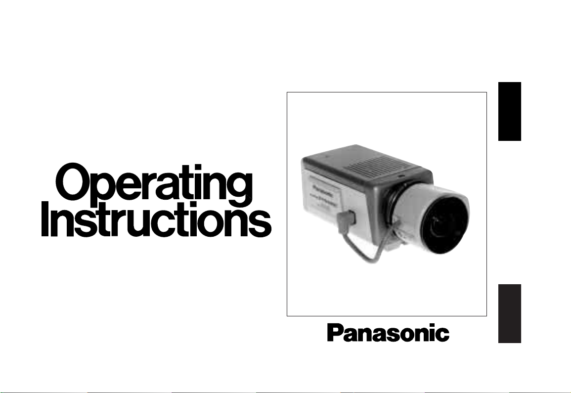
CCTV Cameras
WV-BP550/WV-BP554
(Lens : option)
Before attempting to connect or operate this product,
please read these instructions completely.
FRANÇAIS
ENGLISH
WARNING:
TO PREVENT FIRE OR ELECTRIC SHOCK HAZARD, DO NOT EXPOSE THIS APPLIANCE TO RAIN OR MOISTURE.
The lightning flash with arrowhead
symbol, within an equilateral triangle, is
intended to alert the user to the presence of uninsulated "dangerous voltage" within the product's enclosure that
may be of sufficient magnitude to constitute a risk of electric shock to persons.
The exclamation point within an equilateral triangle is intended to alert the
user to the presence of important operating and maintenance (servicing)
instructions in the literature accompanying the appliance.
The serial number of this product may be found on the top
of the unit.
You should note the serial number of this unit in the space
provided and retain this book as a permanent record of your
purchase to aid identification in the event of theft.
Model No.
Serial No.
Warning:
This equipment generates and uses radio frequency energy
and if not installed and used properly, i.e., in strict accordance with the instruction manual, may cause harmful
interference to radio communications. It has been tested
and found to comply with the limits for a Class A computing
device pursuant to Subpart J of Part 15 of FCC Rules,
which are designed to provide reasonable protection
against such interference when operated in a commercial
environment.
CAUTION:
TO REDUCE THE RISK OF ELECTRIC SHOCK, DO
NOT REMOVE COVER (OR BACK). NO USER SERVICEABLE PARTS INSIDE.
REFER SERVICING TO QUALIFIED SERVICE PERSONNEL.
CAUTION
RISK OF ELECTRIC SHOCK
DO NOT OPEN
SA 1965
SA 1966
For U.S.A

CONTENTS
PREFACE ........................................................................................................................................................................ 2
FEATURES ...................................................................................................................................................................... 2
PRECAUTIONS ............................................................................................................................................................... 3
MAJOR OPERATING CONTROLS AND THEIR FUNCTIONS ......................................................................................... 4
CONNECTIONS .............................................................................................................................................................. 7
FOCUS OR FLANGE-BACK ADJUSTMENT ................................................................................................................. 12
INSTALLATION OF CAMERA ....................................................................................................................................... 13
SETUP ........................................................................................................................................................................... 14
1. CAMERA SET UP MENU ....................................................................................................................................... 14
2. SETUP OPERATION .............................................................................................................................................. 16
SETTING PROCEDURES .............................................................................................................................................. 19
PREVENTION OF BLOOMING AND SMEAR ................................................................................................................ 31
SPECIFICATIONS ......................................................................................................................................................... 32
STANDARD ACCESSORIES ......................................................................................................................................... 33
OPTIONAL ACCESSORIES .......................................................................................................................................... 33
-1-
ENGLISH

1. The following functions are built in.
(1) Auto Light Control (ALC)/Electronic Light
Control (ELC)
(2) The SUPER-D function eliminates interference
by strong background lighting which makes
the camera picture dark, such as a spotlight.
Dynamic range of 40 dB.
(3) Various External Sync Functions, including
Gen-Lock
(4) Electronic Shutter Function
2. Signal-to-noise ratio of 50 dB
3. Minimum illumination of 0.08 lux (0.008 footcandle)
with F 1.4 lenses.
4. Minimum illumination of 0.02 lux (0.002 footcandle)
with Panasonic aspherical high speed (F0.75)
lenses.
5. 570 lines of horizontal resolution
ture elements), and digital signal processing LSI's. This
model offers cutting-edge technology for advanced
video surveillance.
-2-
PREF ACE
Panasonic's WV-BP550 series digital camera introduces a new level of high picture quality and high resolution through the use of a 1/3-inch interline transfer
CCD image sensor having 771 horizontal pixels (pic-
FEATURES
6. High quality picture:
(a) 2H type vertical enhancer for greater picture
sharpness
(b) Minimum of aliasing on fine objects
(c) Expanded dynamic range by use of knee cir-
cuit
(d) Highlight aperture correction for greater pic-
ture detail of bright object
7. Ability to shoot indoor scenes with fixed iris lens by
use of Electronic Light Control (ELC) function.
8. Selectable electronic sensitivity enhancing modes
including : AUTO, MANUAL and OFF
9. Built in Digital Motion Detector

1. Do not attempt to disassemble the camera.
To prevent electric shock, do not remove screws
or covers.
There are no user serviceable parts inside. Ask a
qualified service person for servicing.
2. Handle the camera with care.
Do not abuse the camera. Avoid striking, shaking,
etc. The camera could be damaged by improper
handling or storage.
3. Do not expose the camera to rain or moisture,
or try to operate it in wet areas.
Turn the power off immediately and ask a qualified
service person for servicing. Moisture can damage
the camera and also create the danger of electric
shock.
4. Do not use strong or abrasive detergents when
cleaning the camera body.
Use a dry cloth to clean the camera when dirty.
In case the dirt is hard to remove, use a mild
detergent and wipe gently.
5. Clean the CCD faceplate with care.
Do not clean the CCD with strong or abrasive
detergents. Use lens tissue or a cotton tipped
applicator and ethanol.
6. Never face the camera towards the sun.
Do not aim the camera at bright objects. Whether
the camera is in use or not, never aim it at the sun
or other extremely bright objects. Otherwise,
blooming or smear may be caused.
7. Do not operate the camera beyond the
specified temperature, humidity or power
source ratings.
Use the camera under conditions where temperature is between −10°C - +50°C (14°F - 122°F), and
humidity is below 90%. The input power source is
120V AC 60Hz for WV-BP550 and DC 12V/AC 24V
for WV-BP554.
-3-
Caution:
To prevent fire or electric shock hazard, a UL
listed wire (VW-1, style 1007) should be used for
DC 12V or AC 24V Input Terminals.
PRECAUTIONS
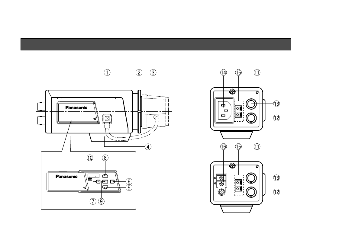
MAJOR OPERATING CONTROLS AND THEIR FUNCTIONS
-4-
SUPER
DYNAMIC
WV-
BP550
SUPER
DYNAMIC
WV-
BP550
Hi-Z G/L 75Ω
VIDEO OUT
POWER
120V AC 60Hz
GEN-LOCK
ALARM OUT
GND
VIDEO OUT
POWER
GEN-LOCK
ALARM OUT
GND
AC 24V
IN
DC 12V
IN
1
2
GND
<WV-BP550>
<WV-BP554>
MAJOR OPERATING CONTROLS AND THEIR FUNCTIONS
Slide the panel to the left until it locks.

q Auto Iris Lens Connector
This connector is used to connect with the auto iris
lens by a 4-pin male connector that is supplied as
a standard accessory (Part No. YFE4191J100).
w Flange-back Adjusting Ring
This ring is used to adjust the back focal length or
picture focus. Rotate this ring clockwise for a Cmount lens or counterclockwise for a CS-mount
lens.
e Lens (Option)
r Camera Mounting Screw Hole
This hole is used to mount the camera onto a
mounting bracket.
t Down Button ( )
This button is used to move the cursor downward.
It is also used to select items in the CAM SET UP
menu.
y Right Button ( )
This button is used to move the cursor to the right.
It is also selects the mode and can be used to
adjust some levels.
u Left Button ( )
This button is used to move the cursor to the left. It
also selects the mode and can be used to adjust
some levels.
i Up Button ( )
This button is used to move the cursor upward. It
is also used to select items in the CAM SET UP
menu.
o Set Button ( )
This button is used to activate an item selected in
the CAM SET UP menu.
!0 Gen-lock Termination Switch (Hi-Z, G/L 75Ω)
Set this switch to Hi-Z when a gen-lock video input
signal is looped through. In all other cases, set this
switch to 75Ω.
!1 Power indicator
This indicator lights up when the power of this
camera is on.
!2 Gen-lock Input Connector (GEN-LOCK)
This connector is used to connect an external system for synchronization.
-5-

!3 Video Output Connector (VIDEO OUT)
This connector is used to connect with the VIDEO
IN connector of the monitor.
!4 Power Cord Socket
This socket is used to connect the power cord
(supplied as a standard accessory).
!5 Alarm Output Terminal (ALARM OUT/GND)
This terminal is used to connect to the ALARM
INPUT connector (terminal) of an external equipment. When this camera detects motion, the alarm
output signal is supplied to the connected external
equipment.
(Open collector output: 16V DC 100mA max.)
!6 AC/DC Compatible Input Terminal
(DC 12V IN/AC 24V IN)
This terminal is for connecting the 12 V DC or 24 V
AC power supply cord.
-6-
Cautions:
1. Connect to 12V DC (10.5V-16V) or 24V AC
(19.5V-28V) class 2 power supply only.
Make sure to connect the grounding lead
to the GND terminal when the power is
supplied from a 24V AC power source.
2. To prevent fire or electric shock hazard,
use a UL listed wire VW-1, style 1007 cable
for the Input Terminal.
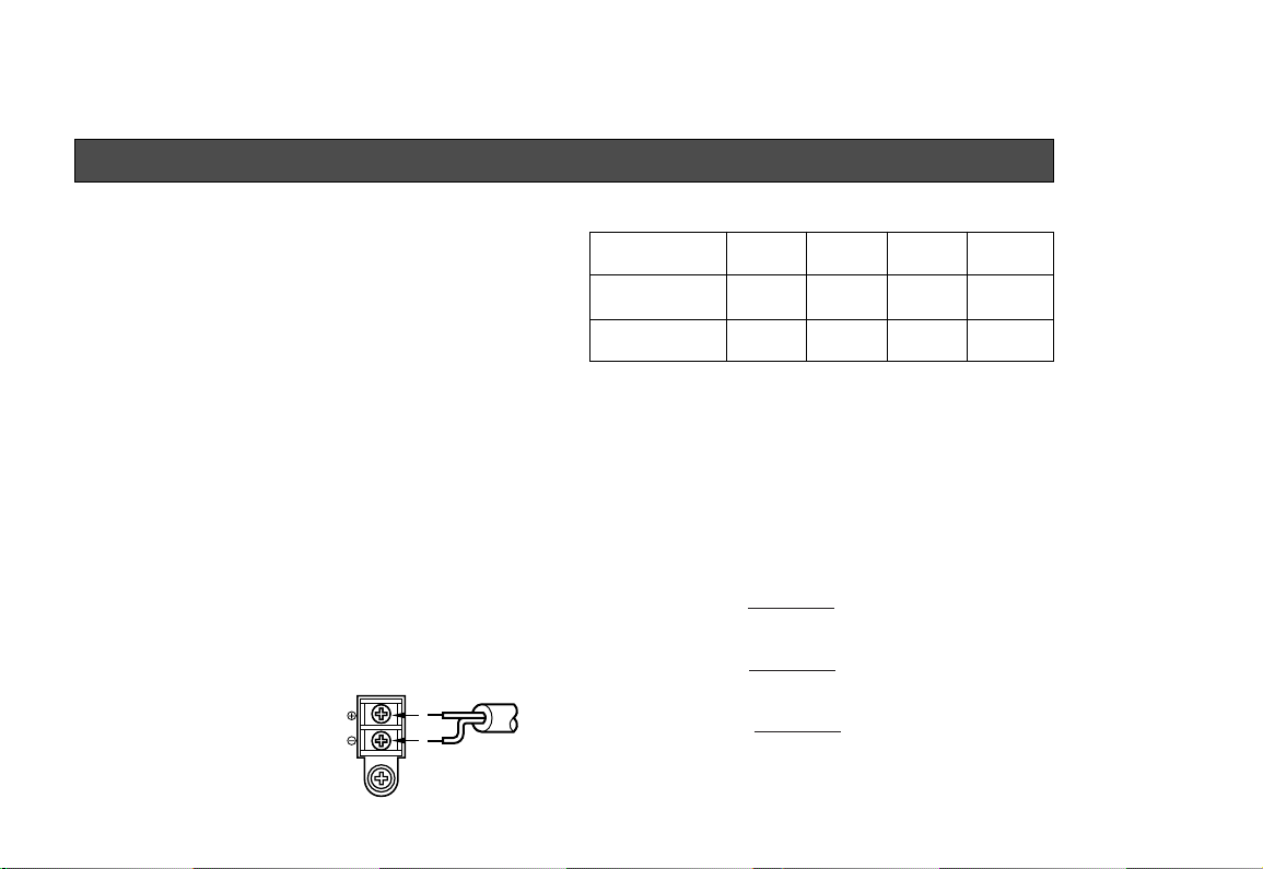
Copper wire #24 #22 #20 #18
size (AWG) (0.22mm2) (0.33mm2) (0.52mm2) (0.83mm2)
Resistance 0.078 0.050 0.030 0.018
Ω/m
Resistance 0.026 0.017 0.010 0.006
Ω/ft
-7-
A. WV-BP550 (120V AC 60Hz)
1. Connect the AC power cord (supplied as standard
accessory) to the power cord socket of the camera.
2. Connect the AC power cord to an electrical outlet
of 120V AC 60 Hz.
Notes:
• Connect the power cord firmly.
• The power cord should be long enough for panning and tilting.
If the cable is too short, the power cord plug may
pulled off the camera when the camera pans or
tilts.
B. WV-BP554 (12V DC/24V AC)
The WV-BP554 has an AC/DC compatible input terminal. The 12V DC or 24V AC power supply cord can be
connected to this terminal. The camera detects the
power source automatically.
1. 12 V DC Power Supply
Connect the power cord to
the AC/DC compatible
input terminal on the rear
panel of the camera.
Resistance of copper wire [at 20°C (68°F)]
AC 24V
IN
DC 12V
IN
1
2
GND
12 VDC
(10.5 V - 16 V)
• Calculation method of maximum cable length
between camera and power supply.
10.5V DC ≤ V
A − (R x 0.42 x L) ≤ 16V DC
L : Cable length (meter)
R : Resistance of copper wire (Ω/meter)
V
A : DC output voltage of power supply unit
V
A − 12
L standard = (meters)
0.42 x R
V
A − 16
L minimum = (meters)
0.42 x R
V
A − 10.5
L maximum = (meters)
0.42 x R
CONNECTIONS
2. 24 V AC Power Supply
Connect the power cable to the AC/DC compatible
input terminal on the rear panel of the camera.
Copper wire #24 #22 #20 #18
size (AWG) (0.22mm2) (0.33mm2) (0.52mm2) (0.83mm2)
Length (m) 95 150 255 425
of Cable
(Approx.) (ft) 314 495 842 1,403
Recommended wire gauge sizes for 24V AC line.
AC 24V
IN
DC 12V
IN
1
2
GND
24 VAC, 60 Hz
(19.5 V - 28 V)
-8-
Caution:
To prevent fire or electric shock hazard, a
UL listed wire (VW-1, style 1007) should be
used for the cable.
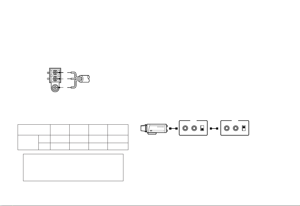
Video Cable
1. It is recommended to use a monitor whose resolution is at least equal to that of the camera.
2. Set the termination switch to the 75Ω position on
the last monitor.
A. Use a 75Ω coaxial cable.
B. Set the termination switch to the 75Ω position
on the last monitor and to the Hi-Z position on
the other monitors. Do not change the positions after setting.
C. The maximum extensible coaxial cable length
between the camera and the monitor is shown
below.
OUTIN 75Ω
Hi-Z
VIDEO
OUTIN 75Ω
Hi-Z
VIDEO
Monitor
Monitor

-9-
Type of RG-59/U RG-6U RG-11/U RG-15/U
coaxial cable (3C-2V) (5C-2V) (7C-2V) (10C-2V)
Recommended (m) 250 500 600 800
maximum
cable length (ft) 825 1,650 1,980 2,640
3. Wiring precautions:
• Do not bend the coaxial cable into a curve whose
radius is smaller than 10 times the cable’s diameter.
• Never staple the cable even if with circular staples. Impedance mismatching will occur.
• Never crush or pinch the cable.
All of the above will change the impedance of the
cable and cause poor picture quality.
 Loading...