

Panasonic WV-BP50 User Manual
• Auto Light Control (ALC)/Electronic Light
Control (ELC)
• Automatic Gain Control (AGC) +18 dB
• Minimum illumination of 0.08 lx (0.008 footcandle) at F1.4
FEATURES
• Signal-to-noise ratio of 46 dB
• Horizontal resolution of 380 lines
• Easy connection with specified monitor by a
coaxial cable
1. Do not attempt to disassemble the camera.
To prevent electric shock, do not remove
screws or covers.
There are no user serviceable parts inside.
Ask a qualified service person for servicing.
2. Handle the camera with care.
Do not abuse the camera. Avoid striking,
shaking, etc. The camera could be damaged
by improper handling or storage.
3. Do not expose the camera to rain or
moisture, or try to operate it in wet areas.
Turn the power off immediately and ask a
qualified service person for servicing.
Moisture can damage the camera and also
create the danger of electric shock.
4. Do not use strong or abrasive detergents
when cleaning the camera body.
Use a dry cloth to clean the camera when
dirty.
In case the dirt is hard to remove, use a mild
detergent and wipe gently.
5. Clean the CCD faceplate with care.
Do not clean the CCD with strong or abrasive
detergents. Use lens tissue or a cotton tipped
applicator and ethanol.
6. Never face the camera towards the sun.
Do not aim the camera at bright objects.
Whether the camera is in use or not, never
aim it at the sun or other extremely bright
objects. Otherwise, blooming or smear may
be caused.
7. Do not operate the camera beyond the
specified temperature, humidity or power
source ratings.
Use the camera under conditions where temperature is between –10°C - +50°C (14°F 122°F), and humidity is below 90 %.
PRECAUTIONS
CCTV Camera
WV-BP50E
Before attempting to connect or operate this product,
please read these instructions carefully.
N0499-0 YWV8QA5178AN Printed in Japan
N 30
CAUTION
RISK OF ELECTRIC SHOCK
DO NOT OPEN
CAUTION:
TO REDUCE THE RISK OF ELECTRIC
SHOCK, DO NOT REMOVE COVER (OR
BACK), NO USER SERVICEABLE PARTS
INSIDE.
REFER SERVICING TO QUALIFIED SERVICE
PERSONNEL.
The exclamation point within an
equilateral triangle is intended to
alert the user to the presence of
important operating and maintenance (servicing) instructions in the
literature accompanying the appliance.
The lightning flash with arrowhead
symbol, within an equilateral triangle, is interned to alert the user to
the presence of uninsulated "dangerous voltage" within the product's
enclosure that may be of sufficient
magnitude to constitute a risk of
electric shock to persons.
WARNING:
TO PREVENT FIRE OR ELECTRIC SHOCK HAZARD, DO NOT EXPOSE THIS APPLIANCE TO
RAIN OR MOISTURE.
The serial number of this product may be found on
the top of the unit.
You should note the serial number of this unit in the
space provided and retain this instruction as a permanent record of your purchase to aid identification
in the event of theft.
Model No.
Serial No.
We declare under our sole responsibility that the
product to which this declaration relates is in conformity with the standards or other normative documents
following the provisions of Directive EEC/89/336.
Wij verklaren als enige aansprakelijke, dat het product waarop deze verklaring betrekking heeft, voldoet
aan de volgende normen of andere normatieve documenten, overeenkomstig de bepalingen van Richtlijn
89/336/EEC.
Vi erklærer os eneansvarlige for, at dette produkt,
som denne deklaration omhandler, er i overensstemmelse med standarder eller andre normative dokumenter i følge bestemmelserne i direktiv 89/336/EEC.
Vi deklarerar härmed värt fulla ansvar för att den produkt till vilken denna deklaration hänvisar är i
överensstämmelse med standarddokument, eller
andra normativa dokument som framstölls i EECdirektiv nr. 89/336.
Ilmoitamme yksinomaisella vastuullamme, että tuote,
jota tämä ilmoitus koskee, noudattaa seuraavia standardeja tai muita ohjeellisia asiakirjoja, jotka noudattavat direktiivin 89/336/EEC säädöksiä.
Vi erklærer oss alene ansvarlige for at produktet som
denne erklæringen gjelder for, er i overensstemmelse
med følgende normer eller andre normgivende dokumenter som følger bestemmelsene i direktiv 89/336/
EEC.
Dichiariamo sotto nostra esclusiva responsabilità che
il prodotto a cui si riferisce la presente dichiarazione è
conforme agli standard o altri documenti normativi
ottemperanti alle disposizioni della direttiva CEE/89/
336.
qwe
r t yi!0
u
o
!1
ALC
BLC
OFF ON
ELC
ALC NC ELC
ALC
BLC
OFF ON
ELC
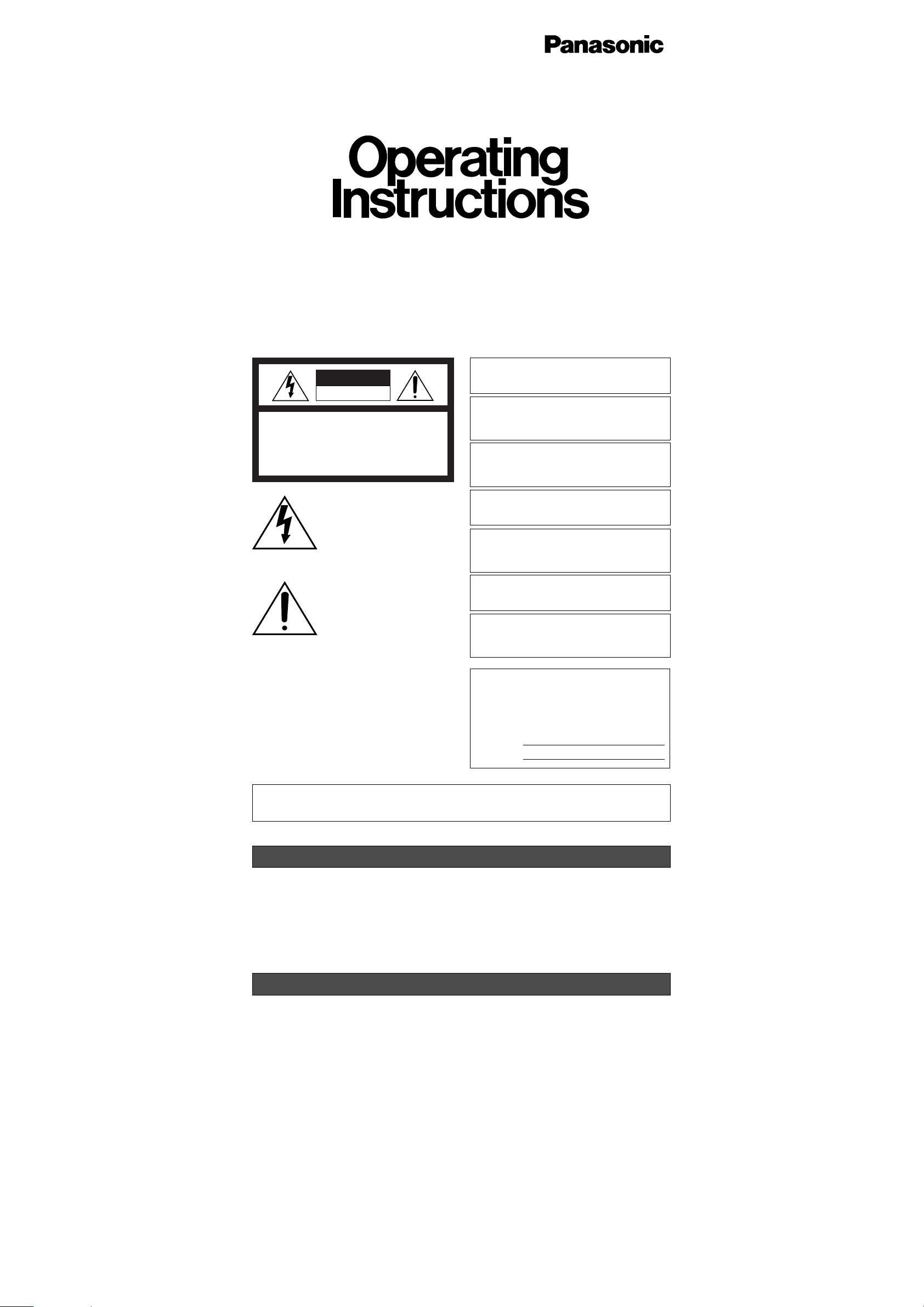
MAJOR OPERATING CONTROLS AND THEIR FUNCTIONS
q Camera Mounting Bracket
Install on the wall or ceiling. See INSTALLING
PROCEDURE below.
w Pan Fixing Ring
Tighten after adjusting the pan angle.
e Pan Head
Attach the camera on this.
r Auto Iris Lens Connector
Supplies power and DC control signals to an
auto iris lens (not supplied).
t Flange-back Adjusting Ring
This ring adjusts the back-focal distance or
picture focus.
y Lens (option)
u Camera Mounting Adapter
There is a hole for mounting the camera onto
a mounting bracket. The camera is originally
designed to be mounted from the bottom, but
a top-mounting type is also available. To
mount from the top, remove the mount
adapter from the bottom of the camera by
removing two fixing screws. Attach the mount
adapter to the top as shown in the diagram,
then mount the camera on the mounting
bracket. Make sure that two original screws
are used when mounting the mount adapter;
longer type screws may damage inner components.
i Lens Selector
Detach the cover from the camera and select
the mode according to the lens type that is
mounted on this camera.
ALC: Select this mode when an auto iris lens
(ALC lens) is mounted on this camera.
NC: Not used.
ELC: Select this mode when a fixed iris lens
or manual iris lens is mounted on this
camera.
!1 Back Light Compensation Mode Selector
(BLC ON, OFF)
Select the mode according to the position of
the object and light conditions.
When the ALC lens is mounted on this camera, select the mode with upper selector.
When the fixed iris or manual iris lens is
mounted, select with the lower selector.
ON: Select this mode when a strong light
such as a spotlight is in the background.
OFF: Normal picture.
o Coaxial Cable Connector
Connect a coaxial cable (to be procured
locally) between this connector and the CAMERA IN connector of the specific monitor (or
Camera Drive Unit).
Monitor supplies power to the camera, and
the camera supplies the video output to the
monitor through the coaxial cable.
!0 Rear Cover
The rear cover can be removed to gain
access to the switches.
ALC
NC
ELC
Rear Cover
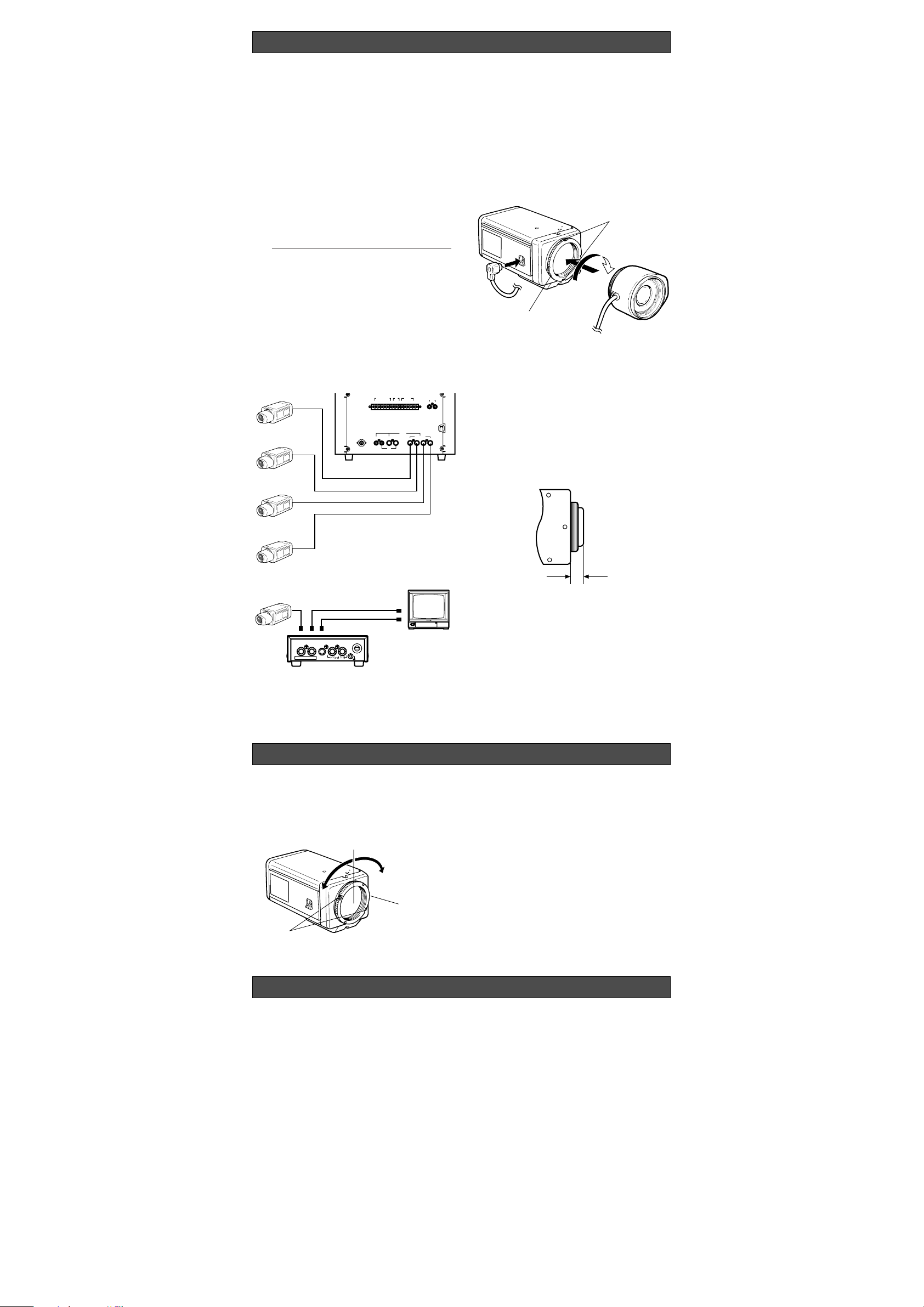
CONNECTIONS
The following adjustment should be made by
qualified service personnel or system installers.
q Loosen the screws on the flange-back adjust-
ing ring.
w Turn the flange-back adjusting ring to the
desired position.
Caution: Do not rotate the ring counterclock-
wise by force after it stops. If the ring is
rotated by force, the inner lens or CCD
image sensor may be damaged.
e Tighten the screws on the flange-back adjust-
ing ring.
FOCUS OR FLANGE-BACK ADJUSTMENT
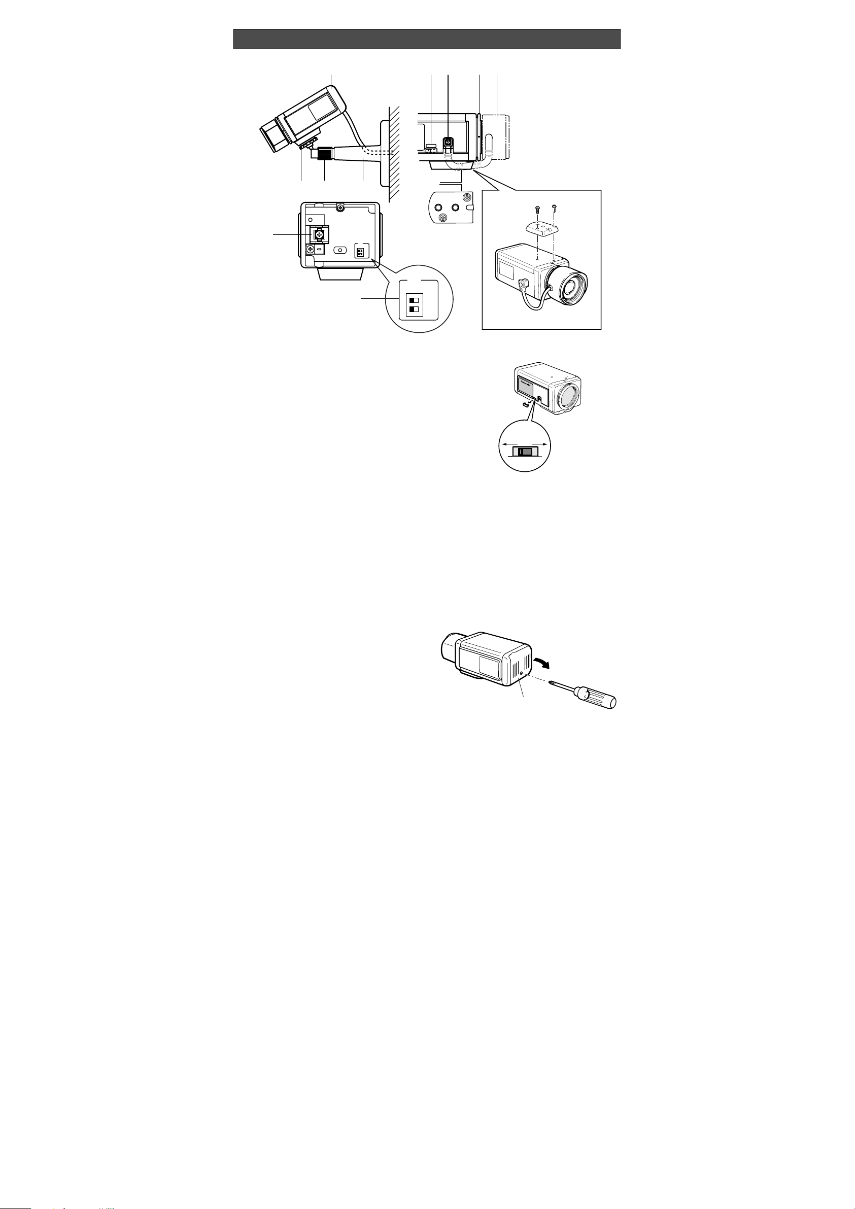
Mounting the Lens
Caution:
Before you mount the lens, loosen the two
screws on the ring, and rotate this ring clockwise until it stops. If the ring is not at the end,
the inner glass or CCD image sensor may be
damaged.
q Mount the lens by turning it clockwise on the
lens mount of the camera.
w Connect the lens cable to the auto iris lens
connector on the side of the camera.
q
w
Screws
Flange-back
Adjusting Ring
Caution for Mounting the Lens
The lens mount should be a C-mount or CS-mount
(1”-32UN) and the lens weight should be less than
450 g (0.99 lbs). If the lens is heavier, both the
lens and camera should be secured by using the
supporter.
The protrusion at the rear of the lens should be as
shown in the diagram.
CS-mount: Less than 8 mm (5/16”)
qe
w
Flange-back
Adjusting Ring
Screws
Caution: Keep the POWER switch of the specified
monitor, Camera Extension Unit and Camera
Drive Unit in OFF position during connections. If the power of these units are ON during connections, the camera does not function due to protect circuit from misconnection.
• Basic System
Connect the single coaxial cables between
the Camera and Camera Input Terminal of
Specified monitor or Camera Drive Unit. The
approx. maximum cable length is as:
Coaxial Maximum DC R/1 000 ft.
Cable Cable of Inner
Type Length Conductor
RG-59/U 200 m (660 ft) Less than
30
Ω
RG-6/U 500 m (1 650 ft) Less than
12 Ω
The maximum DC resistance between the
camera and these units is 20 Ω.
• Connection Diagram
Coaxial
Cable
2
12341234
GND GNDSTDBY
ALARM CONTROL
OUT
ALL
MODE
RESETRECOVER
SPOT MONITOR CONTROL IN REMOTE OUT
1
CAMERA INPUT
CAMERA
VTR
43
REC
OUT
AUDIOINAUDIO
OUT
CAMERA
EXTENSION IN
PLAY
IN
OUT IN
TIMING
SELECT
Video Monitor
WV-BM140
CAMERA
IN
VIDEO
OUT
AUDIO
OUT
VD/SYNC
IN
VD/SYNC
OUT
SIGNAL
GND
CAUTION
USE WITH SPECIFIED EQUIPMENT SEE
ITS MANUAL BEFORE CONECTING.
Camera
Video Monitor
Video
Audio
Camera Drive Unit
WV-PS11B
Caution: To use the C-mount lens, the Lens
Mount Converter (C-mount
adapter) WV-
AD20 should be used with the camera.
The mounting bracket can be fixed either on the
top or the bottom cover of the camera.
When mounting on the top cover of the camera,
detach the mount adapter from the bottom of the
camera cover and attach it on the top cover of the
camera.
1. Fix the camera mounting bracket on the wall
or ceiling to be installed by two screws (to be
procured locally).
2. Insert the camera fixing screw on the pan
head into the camera mounting adapter, and
tighten the pan head firmly.
3. Connect the camera and the monitor with the
coaxial cable (to be procured locally).
INSTALLING PROCEDURE
 Loading...