

Panasonic WV-BP310 User Manual
Operating
Instructions
CCTV Cameras
WV-BP310/WV-BP314
Panasonic
allc-nplirg (o C9nnect ?r op*(a(» tni| proaiKl,
dl«as« i«ad lltiiKo mutructon« C0Tip:»(»ly.

A
CAUTION
RtSK OF ELECTRIC SHOCK
DO NOT OPEN
A
CAUTION:
TO REDUCE THE RISK OF ELECTRIC SHOCK, DO
NOT REMOVE COVER {OR BACK). NO USER SER
VICEABLE PARTS INSIDE,
REFER SERVICING TO QUALIFIED SERVICE PER
SONNEL
The lightning flash with arrowhead
symbol, within an equilateral triangle, is
intended to alert the user to the pres
ence of uninsulated "dangerous volt
age" within the product's enclosure that
A
SA 1965
WARNING:
TO PREVENT FIRE OR SHOCK HAZARD. DO NOT EXPOSE THIS APPLIANCE TO RAIN OR MOISTURE.
may be of sufficient magnitude to con
stitute a risk of electric shock to per
sons.
The exclamation point within an equi
lateral triangle is intended to alert the
user to the presence of important oper
ating and maintenance (servicing)
instructions in the literature accompa
nying the appliance.
-------------------------------------------------------------------------------------------------Fof U.S.A—
Warning:
This equipment generates and uses radio frequency energy
and if not installed and used properly, i.e., in strict accor
dance with the instruction manual, may cause harmful
interference to radio communications. It has been tested
and found to comply with the limits for a Class A computing
device pursuant to Subpart J of Part 15 of FCC Rules,
which are designed to provide reasonable protection
against such interference when operated in a commercial
environment.
The serial number of this product may be found on the bot
tom of the unit.
You should note the serial number of this unit in the space
provided and retain this book as a permanent record of your
purchase to aid identification in the event of theft.
Model No. _____________________________________
Serial No.

CAUTION:
Before attempting to connect or operate this prod
uct, please read the Isabel on the bottom.
CONTENTS
PREFACE
FEATURES..................................................................2
PRECAUTIONS
MAJOR OPERATING CONTROLS AND
THEIR FUNCTIONS.....................................................4
CONNECTIONS ........................................................ 7
LENSES.....................................................................10
FOCUS OR FLANGE-BACK ADJUSTMENT
INSTALLATION OF CAMERA
PREVENTION OF BLOOMING AND SMEAR...........19
LENS MAINTENANCE AND CLEANING
SPECIFICATIONS
STANDARD ACCESSORIES....................................21
OPTIONAL ACCESSORIES
..............
^....................................................2
..........................................................
...................................
.....................................................
....................................
............
.................
18
19
20
21
3
17
-1-

PREFACE
FEATURES
Panasonic's WV-BP310 series cameras introduce a
new level of high picture quality through the use of a
1/3 inch interline transfer CCD having 771 horizontal
pixels (picture elements). High performance-to-cost
ratio is achieved through the use of newly developed
Sync IC's and ability to shoot indoor scenes with a
fixed iris lens by use of-Electronic Light Control (ELC)
function.
Minimum illumination of 0.008 footcandle (0.08 lux)
at FI.4 and signal-to-noise ratio of 46 dB by
employing a 1/3 inch interline transfer CCD image
sensor with 771 (H) x 492 (V) pixels.
570 lines of horizontal resolution
Either optional standard C-mount or Special Cmount (CS-mount) auto iris control lens can be
used with.
Selectable auto iris control signal for the lens
either a video signal or DC control signal.
Various Sync functions, including Gen-lock.
Ability to shoot indoor scene with a fixed iris lens
by use of the Electronic Light Control (ELC) func
tion.
-2-

PRECAUTIONS
1. Do not attempt to disassemble the camera.
To prevent electric shock, do not remove screws
or cover.
There are no user-serviceable parts inside.
Refer servicing to qualified service personnel.
2. Handle the camera with care.
Do not abuse the camera. Avoid striking or shak
ing it.
The camera could be damaged by improper han
dling or storage.
3. Do not expose the camera to rain or moisture,
or try to not operate it in wet areas.
Do take immediate action if ever the camera does
become wet. Turn the power off and refer servic
ing to qualified service personnel. Moisture can
damage the camera and can also create the dan
ger of electric shock.
4. Never face the camera towards the sun.
Whether the camera is in use or not, never face it
towards the sun. Do use caution when operating
the camera in the vicinity of spot lights or other
bright lights and light reflecting objects.
5. Do not operate the camera beyond its tempera
ture, humidity or power source ratings.
Do not use the camera in an extreme environment
where high temperature or high humidity exist.
Use the camera under conditions where the tem
perature is within -22°F - 122°F (-30°C - +50^C),
and the humidity is below 90%. The input power
source is 120V AC 60 Hz for VW-BP310 or 24V AC
60 Hz for WV-BP314.
Caution:
To prevent fire or shock hazard, the UL list
ed wire VW-1, style 1007 should be used for
AC 24V Input Terminals.
-3-
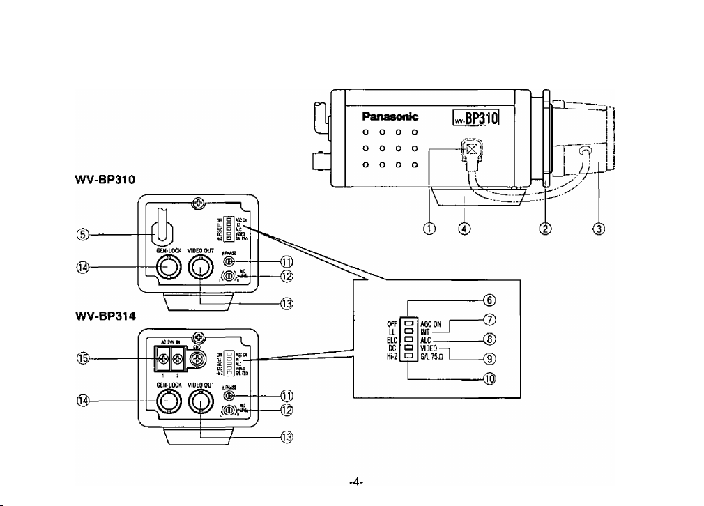
MAJOR OPERATING CONTROLS AND THEIR FUNCTIONS

(1) Auto Iris Lens Connector
This 4-pin female connector supplies the power
and either video signal or DC control signal to the
auto iris lens.
A 4-pin male connector, which can be mated with
the camera's female connector, is supplied as a
standard accessory (Part No. YFE4191J100).
This male connector can be installed on lenses
■ which have incompatible type connector.
See page 16 for installation details
(2) Flange-back Adjusting Ring
This ring is used to adjust the back focal length or
picture focus by rotating this ring to clockwise for
C-mount lens or counterclockwise for special Cmount (CS-mount) lens.
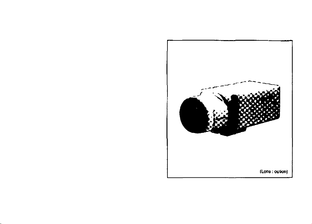
(3) Lens (Option)
See pages 10, 11, 12, 13 and 14 for details on
lens selection.
(4) Camera Mounting Screw Hole
This threaded hole(1/4”-20) is used to mount the
camera onto a mounting bracket or tripod.
(5) Power Cord
(6) AGC On/Off Switch (AGC ON/OFF)
This switch is used to select the gain of the video
amplifier as follows;
ON: When the lens iris is fully opened under a low
light condition, a clear picture is obtained by
automatic increase of the gain.
OFF: A natural and low-noise picture is obtained
under a low light condition.
(7) Sync Selection Switch (INT/LL)
This switch is used to select the camera synchro
nization mode.
INT: When no signal is supplied to the Gen-lock
Connector, the camera synchronization mode
is set to internal 2 : 1 interlace.
Whenever the Gen-lock video signal is sup
plied to the Gen-lock Connector, the camera
synchronization mode is automatically set to
external synchronization.
LL: The camera synchronization mode is set to the
Line-lock even if the Gen-lock video signal is
supplied to the Gen-lock Connector,
Note: Set this switch to the INT position for Gen
lock operation,
(8) Electronic Light Control / Automatic Light
Control Selection Switch (ELC/ALC)
This switch is used to select the lens as follows.
ALC: Choose this position when u sing an auto iris
lens.
ELC: Choose this position when using a fixed or
manual iris lens.
-5-

(9) Lens Selection Switch (VIDEO/DC)
This switch is used to select the supplied auto iris
control signal to the lens from the Auto Iris Lens
Connector(l).
DC: Choose this position when the auto iris control
lens requiring DC control signal such as lens
es shown on pages 10,11, 12 and 13.
VIDEO: Choose this position when the auto iris
control lens requiring video signal such as
WV-U\8B, WV-LA16B, WV-LA25B, WV-LA50B,
is mounted on the camera.
(10) Gen-lock Termination Switch (G/L 75Q / Hiz)
When looping through the Gen-lock video input
signal, set this switch to the Hi-Z position and in all
other cases, set this switch to the 75-ohm position.
(11) Vertical Phase Control (V.PHASE)
The vertical phase of the camera sigani can be
adjusted to match the vertical phase of the line
power,
(12) Auto Iris Level Control (ALC LEVEL, L(Low)/
H(High))
This control adjusts the control level of the auto iris
control when the Lens Selection Switch (9) is set to
the DC position and the auto iris lens which
requires the DC control voltage such as WV-LA12
etc., is mounted on the camera.
Note: When the Lens Selection Switch (9) is set to
the VIDEO position, the auto iris control level
should be adjusted by the lens.
(13) Video Output Connector (VIDEO OUT)
A 1.0 Vp-p/75 ohms composite video signal is pro
vided at this connector.
Whenever the multiplexed vertical drive (VD2) sig
nal is supplied to this connector, the camera syn
chronization mode is automatically set to Vertical
Drive Lock.
(14) Gen-lock Video Input Connector (GEN-LOCK)
A composite B/\N or color 1.0 Vp-p/75 ohms video
signal, or black burst 0.3 Vp-p/75 ohms or com
posite sync 4 Vp-p/75 ohms should be supplied to
this connector for external synchronization.
(15) AC 24V In Terminal (AC 24V IN)
This terminal accepts 24V AC power source
(19.5V-28V), Be sure to connect grounding lead to
the GND terminal.
Cautions :
1, Connect this to a 24V AC class 2 power sup
ply only.
2. To prevent fire or shock hazard, the UL listed
wire VW-1, style 1007 should be used for the
cable for AC 24V Input Terminal.
-6-
 Loading...