

Panasonic VBHN240SJ25, VBHN320SJ47, VBHN245SJ25, VBHN250SJ25, VBHN325SJ47 General Installation Manual
...
General Installation Manual
Photovoltaic Module HITTM
VBHNxxxSJ25 series
VBHNxxxSJ47 series
Model No.
VBHN240SJ25, VBHN245SJ25, VBHN250SJ25
VBHN320SJ47, VBHN325SJ47, VBHN330SJ47
CONTENTS
SAFETY PRECAUTIONS
・GENERAL INFORMATION
・WARNING
・CAUTIONS
MODULE SPECIFICATIONS
・STANDARDS
・APPLICATION CLASS OF PRODUCT
・FIRE CLASS OF PRODUCT
・JUNCTION BOX AND TERMINALS
・BYPASS DIODE
INSTALLATION
・GENERAL
・OPERATING CONDITIONS
・SPECIAL CONDITIONS
・UNPACKING AND HANDLING
2
3
6
7
VBHNxxxSJ47 series VBHNxxxSJ25 series
Thank you for choosing Panasonic photovoltaic module HITTM.
Please read this manual completely before you install or use of
HITTM. With proper operation and maintenance, HITTM will
provide you with clean, renewable solar electricity for many
years. This manual contains important installation, mainte-
nance and safety information. The word “module” as used in
this manual refers to one or more PV modules. Retain this
manual for future reference.
・MODULE INSTALLATION
WIRING
・GENERAL
・MODULE WIRING
・ARRAY WIRING
・EARTH GROUND WIRING
MAINTENANCE
・ANTI-REFLECTION GLASS SURFACE
CLEANING
・DISPOSAL OF OLD EQUIPMENT
10
11
DISCLAIMER OF LIABILITY
CUSTOMER SERVICES
“HIT” is a trademark of the Panasonic Group.
Other product and service names listed in this
manual are trademarks or registered trademarks
of respective companies.
12
8

SAFETY PRECAUTIONS
WARNING
CAUTIONS
All instructions should be read and
understood before attempting to
install, wire, operate, and maintain
the module.
The installation of modules requires
a great degree of skill and should
only be performed by qualified
licensed professionals, including,
without limitation, licensed contrac-
tors and licensed electricians.
The installer assumes the risk of all
injury that might occur during in-
stallation, including, without limita-
tion, the risk of electric shock.
Before installing modules, contact
the appropriate authorities to de-
termine permissions, installation
and inspection requirements, which
should be followed.
Be sure that the construction or
structure (roof, etc.) where the
modules are being installed has
enough strength.
Both roof construction and module
installation design have an effect on
the fire resistance of a building.
Improper installation may contrib-
ute to fire hazards. Additional de-
vices such as ground fault, fuses,
and disconnects may be required.
For a non-integral module or panel,
the assembly is to be mounted over
a fire resistant roof covering rated
for the application.
For modules mounted on roofs,
special construction or structures
may be required to help provide
proper installation support.
Do not install the module where
flammable gases or vapors are pre-
sent.
Do not use modules of different
specifications in the same system.
Follow all safety precautions of
other system components used.
To avoid the hazard of electric shock,
sparks, fire and injury
The modules generate DC electrical
energy when exposed to sunlight or
other light sources, so cover the
entire front surface of the modules
with a dense, opaque material such
as a cardboard box, during installa-
tion and handling of the modules.
The shock hazard increases as mod-
ules are connected in parallel, pro-
ducing higher current, and as mod-
ules are connected in series, produc-
ing higher voltages.
The shock hazard increases as mod-
ules with nominal open-circuit volt-
age (Voc) in excess of 45 V, and/or
modules rated for maximum system
voltage in excess of 45 V.
Wear suitable clothing, gloves and
guards to prevent from direct con-
tact with 30 VDC or greater.
Work only in dry conditions, with
dry modules and dry tools.
Children and unauthorized persons
should not be allowed near the
installation of modules.
Do not puncture or damage the
back sheet of a module. Do not use
the PV module and make a replace-
ment, when scratch exposing con-
ductive part is found on the back
sheet.
Do not disassemble the module, or
remove any parts installed by the
manufacturer.
Do not open a junction box's lid.
Do not touch the junction box ter-
minals.
Do not change the wiring of bypass
diodes.
Do not connect or disconnect termi-
nals while modules generate elec-
tricity and connect electrical load.
To avoid the hazard of injury, burn and
damage to the module
Use a module for its intended pur-
pose only.
Be sure that all other system com-
ponents are compatible, and they
do not subject the module to me-
chanical or electrical hazards.
Do not artificially concentrate sun-
light on a module.
Do not stand or step on a module.
When carrying a module, two or
more people should carry it by its
frame and wear non-slip gloves.
Do not carry a module by its wires
or junction box.
Do not drop a module.
Do not drop anything on the sur-
face of a module.
Do not hit the back sheet of a mod-
ule by the connector or other
things.
Do not disassemble a module, at-
tempt any repair, open the junction
box cover, nor remove any parts
installed by Panasonic. There are no
user serviceable parts within the
module or junction box.
Do not treat the back sheet or front
surface with paint or adhesives.
Do not use or install broken mod-
ules. If you find a breakdown such
as glass breakage, contact the pro-
fessional installer to replace it
promptly.
Do not touch a module unnecessari-
ly. The glass surface and frames get
hot.
In some areas, local electrical codes
may govern the installation and use
of modules.
Never leave a module unsupported
or unsecured.
2

MODULE SPECIFICATIONS
Module specifications are shown in
Table 1-1, 1-2 and Figure 1-1, 1-1-a,
1-1-b, 1-2. (Electrical specifications,
mechanical specifications, module
dimensions)
1) Rated electrical characteristics are
within the range of +10% to –0% of
the values measured at Standard
Test Conditions (STC). Irradiance of
1000W/m2, 25±2℃ cell tempera-
ture, AM1.5 and solar spectral irra-
diance according to IEC 60904-3.
2) Under normal conditions, a module
may experience conditions that
produce more current and/or volt-
age than reported at standard com-
ponent test conditions. Accordingly,
the values of Isc and Voc should be
multiplied by a factor of 1.25 when
determining voltage ratings, con-
ductor capacities, fuse sizes, and
size of controls connected to the
module output.
3) The current output for the modules
shown in the Specifications is meas-
ured at Standard Test Conditions.
These conditions may not be fre-
quently observed in actual practice.
Table 1-1. Model Specifications
Model VBHN240SJ25 VBHN245SJ25 VBHN250SJ25
Maximum Power (Pmax) +10/-0 % W 240 245 250
Open Circuit Voltage (Voc) ±10 % V 52.4 53.0 53.2
Short Circuit Voltage (Isc) ≧90 % A 5.85 5.86 6.03
Maximum Power Voltage (Vpm) V 43.6 44.3 44.3
Maximum Power Current (Ipm) A 5.51 5.54 5.65
Cell Number in Series pcs 72
Cell Type Silicon hetero-junction*
Maximum System Voltage (Vsys) V 1000
Maximum over-current protection rating A 15
Factory Installed Bypass Diode pcs 43
Length x Width x Height mm 1580 x 798 x 35
Weight kg 15
Silicone hetero-junction*: Mono-crystalline Silicon/amorphous silicon hetero-junction
3
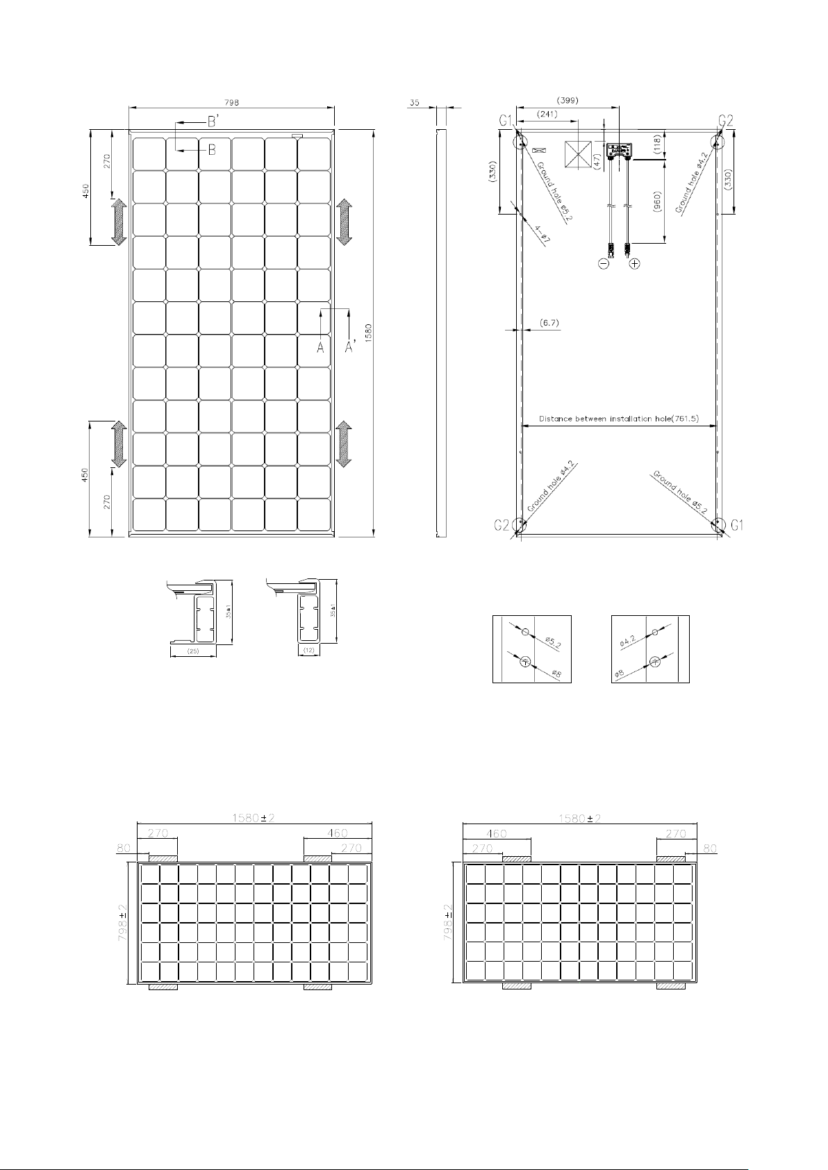
Dimension in mm
Front side
Section A-A’ Section B-B’
Note) A module is installed using 4 points, symmetrical
mounting within setting range (shaded).
Figure 1-1. Module dimensions (VBHNxxxSJ25)
Back side Side
* The positions of the holes are all symmetrical
against the center of the module.
G1
Enlarged view
G2
Note: Fixing span must not exceed 1040mm.
Figure 1-1-a: Optional Mounting Range A
Note: Fixing span must not exceed 1040mm.
Figure 1-1-b: Optional Mounting Range B
4
 Loading...