

Panasonic VA-12020 User Manual
INSTALLATION
COMMERCIAL
STACKED
03
INSTRUCTIONS
WARNING
To reduce the risk of severe injury or death, follow all installation instructions.
•
•
Clothes dryer installation must be performed by a qualified installer.
•
Install the clothes dryer according to these instructions and in accordance with local codes.
• This dryer must be exhausted to the outdoors.
• Use only 4” rigid metal ducting for exhausting the clothes dryer to the outdoors.
• DO NOT install a clothes dryer with flexible plastic ducting materials. If flexible metal (semi-rigid or foil-type) duct is
installed, it must be UL listed and installed in accordance with these instructions and local codes. Flexible venting
materials are known to collapse, be easily crushed, and trap lint. These conditions will obstruct dryer airflow and
increase the risk of fire.
• Do not install or store this appliance in any location where it could be exposed to water and or weather.
• Save these instructions. (Installers: Be sure to leave these instructions with the customer).
BEFORE YOU BEGIN
•
Important
•
Important
•
Note to Installer - Be sure to leave these instructions with the customer.
Note to Customer - Keep these instructions for local inspector’s use.
•
•
Before the old dryer is removed from service or discarded, remove the dryer door.
• Service information and the wiring diagram are located in the control console.
• Do not allow children on or in the appliance. Close supervision is necessary
when the appliance is used near children.
• Install the dryer where the temperature is above 50°F for satisfactory
operation of the dryer control system.
Preparing the Installation Site and Unpacking
the Dryer
1.Prepare the area and exhaust for installation of the new dryer.
2.Check to be sure that the existing external exhaust is clean and that it meets
attached installation specifications.
3.Using the four shipping carton corner posts as padding (two on each side),
carefully lay the dryer on its left side and remove foam shipping pad.
4.Return the dryer to an upright position.
5.Move the dryer to the desired location.
- Save these instructions for local inspector’s use.
- Observe all governing codes and ordinances.
- RISK OF FIRE
- Read these instructions completely and carefully
ELECTRIC DRYERS
Tools and Materials
you will need
Slip joint pliers
Screwdrivers (slotted or phillips
head)
Chains
2" x 4" studs
Wall hoods
Two 3/4” UL recognized strain
relief if the power supply is
from a direct wire.
Two dryer power cord kit UL
listed, rated 120/240V, 30A with
3 or 4 prongs if the power
supply is from a wall receptacle.
4” diameter rigid metal duct,
duct clamps, elbows and
exhaust hood.
Basic safety protection such as
safety goggles, gloves and arm
protection are recommended.
(x2)
INSTALLATION
CAUTION: FOR PERSONAL SAFETY, STACKED
UNITS MUST BE FASTENED SECURELY TO WALL.
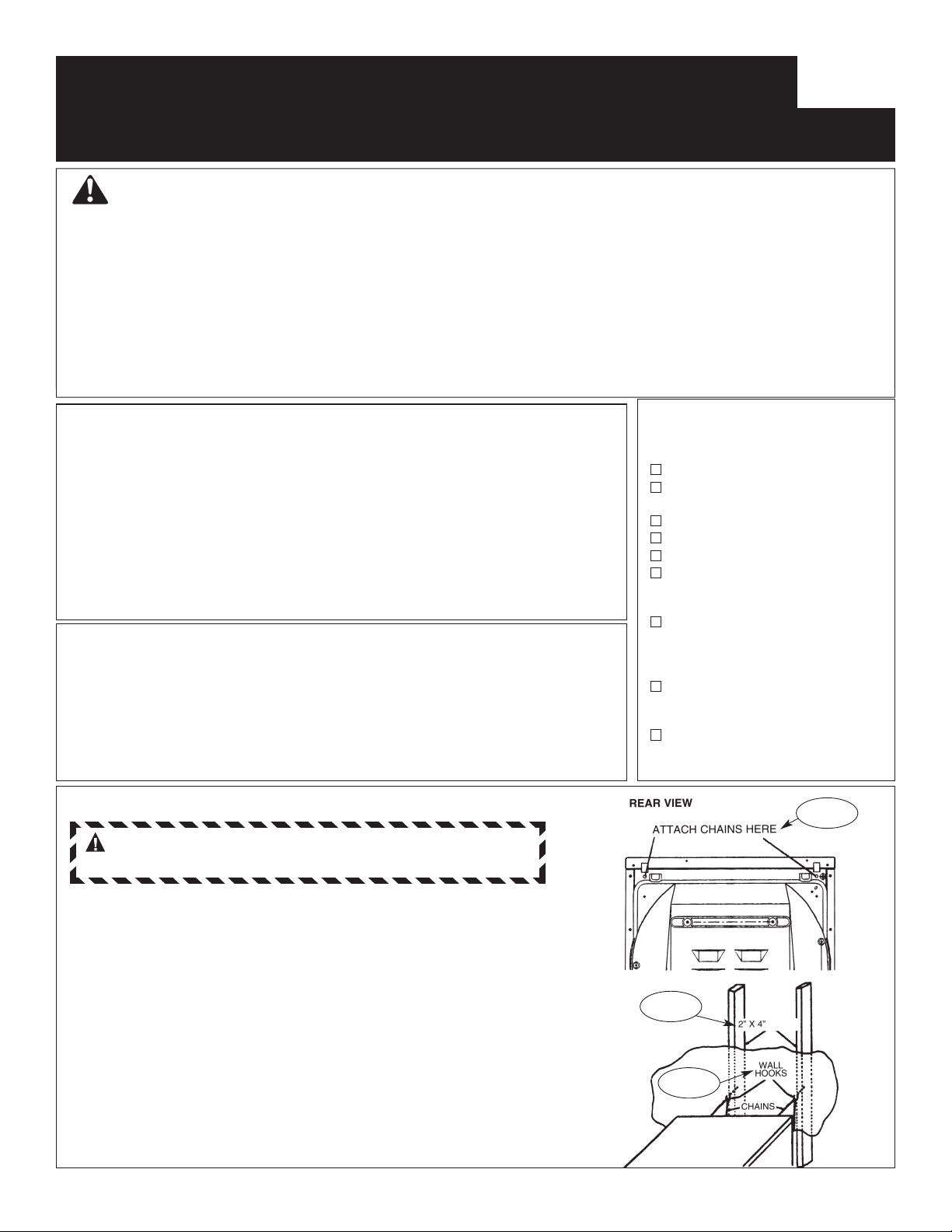
STEP 1
Attach two chains using Phillips head screws to each end of
upper section of cabinet (upper unit).
STEP 2
Locate two wall studs behind desired operating location of
stacked units.
NOTE: For wall studs not appropriately spaced, see section
for Alternate Method for Installation of Wall Hooks.
STEP 3
Screw two wall hooks into two wall studs (same height as
chain connections on cabinet of upper unit). Both chains
should pull straight back to wall studs or angle outward.
NEITHER chain should angle inward.
NOTE: The final construction must withstand a pull of 200 lbs.
STEP 1
STEP 2
STEP 3
500A436P003_Rev0 Pub. #31-16222
INSTALLATION (continued)
STEP 4
Connect both dryers to power supply. (See ELECTRICAL
CONNECTION INFORMATION section of this instruction.)
STEP 5
Connect both dryers to external exhaust. (See EXHAUST
INFORMATION of this instruction.)
STEP 6
Hook both chains from upper unit to appropriate wall hooks
taking up any slack.
STEP 7
Adjust all 4 levelling legs. Dryer must be levelled and rest
firmly on all 4 levelling legs.
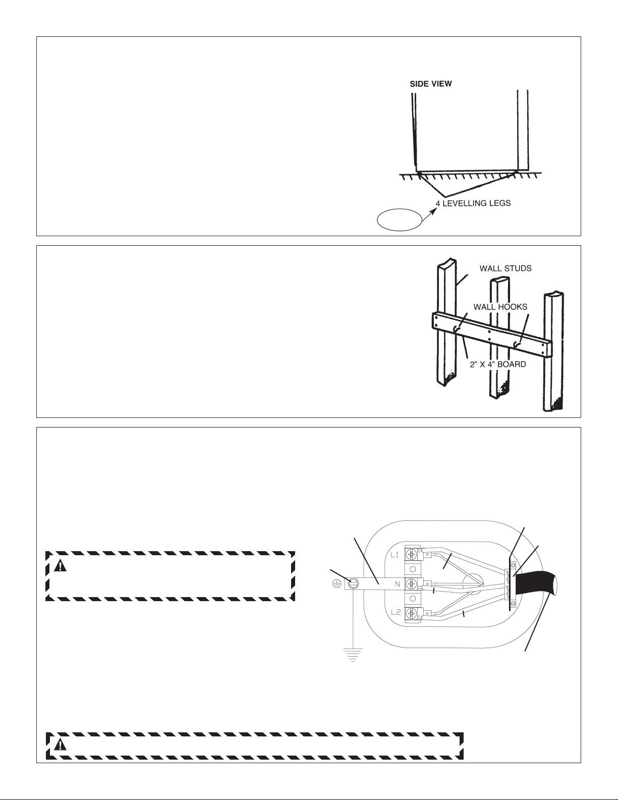
STEP 8
Alternate Method for Installation of Wall Hooks
STEP 1
If wall studs are not correctly spaced or centered behind upper unit, it
may be necessary to attach a horizontal 2" x 4" board to the existing
wall.
STEP 2
Attach wall hooks in approximate position of two chains of upper unit so
each chain pulls straight back to wall.
NOTE: If wall is concrete or block, drill holes and use appropriate wall
anchors. The final construction must withstand a pull of 200 lbs.
CONNECTING DRYER USING 3-WIRE CONNECTION
• Remove the cover near the power cord entry hole.
• Install 3/4" UL recognized strain relief to power cord entry hole. Bring power cord through strain relief.
• Connect two HOT lines to outer screws (L1 & L2) of terminal block.
• Connect NEUTRAL (white) line to center screw (N) of terminal block.
• Tighten all terminal block screws firmly.
• Properly secure power supply cable to strain relief.
• Reinstall the cover.
CAUTION, FOR PERSONAL SAFETY:
THIS APPLIANCE MUST BE PROPERLY
GROUNDED.
Grounding:
• If local codes permit, be sure ground strap is
connected to neutral (centre terminal of block and
to ground screw on rear frame).
• If local codes do not permit frame of dryer to be
grounded to neutral, remove and discard ground
strap. The frame must be grounded by attaching a
ground wire (not supplied) to the green grounding
screw on rear of dryer and to a grounded metal
cold water pipe or other established ground.
GROUND
STRAP
GREEN
GROUND
SCREW
GROUND
TO GREEN
GROUND
SCREW ON
CABINET
REAR
IF REQUIRED, INSTALL
EXTERNAL GROUND (NOT
PROVIDED) TO GROUNDED
METAL COLD WATER PIPE OR
OTHER ESTABLISHED GROUND
DETERMINED BY A QUALIFIED
ELECTRICIAN.
HOT
NEUTRAL
(white)
HOT
3 #10 AWG MINIMUM COPPER
CONDUCTORS OR
120/240V 30A POWER SUPPLY CORD KIT
MARKED FOR USE WITH DRYERS &
PROVIDED WITH CLOSED LOOP OR SPADE
TERMINALS WITH UPTURNED ENDS (NOT
SUPPLIED).
strain relief
bracket
3/4", UL
recognized
strain relief
WARNING: NEVER LEAVE THE TERMINAL BLOCK WITHOUT THE COVER.
 Loading...