

Page 1
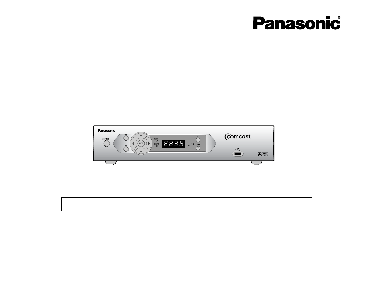
Digital CATV Terminal
Operating Instructions
Model No. TZ-PCD3000
For assistance, please call : your local cable operator
Before connecting, operating or adjusting this product, please read these instructions completely .
Save this manual for future reference.
TQB2AA0489
Page 2
The Class ll insulation symbol(square within a square)indicates that
this product has been evaluated and tested to comply with Class ll
insulation requirements.
11.Only use attachments/accessories specified by the manufacturer.
12.Use only with the cart, stand, tripod, bracket or table specified by
the manufacturer, or sold with the apparatus.
When a cart is used, use caution when moving the cart/apparatus
combination to avoid injury from tipover.
13.Unplug this apparatus during lightning storms or when unused for
long perods of time.
14.Refer all servicing to qualified service personnel. Servicing is required when
the apparatus has been damaged in any way, such as power-supply
cord or plug is damaged,liquid has been spilled or objects have fallen into
the apparatus, the apparatus has been exposed to rain or moisture, does not
operate normally, or has been dropped.
WARNING: To prevent damage which may result in fire or shock hazard,
do not expose this appliance to rain or moisture.
Note To CATV System Installer
This reminder is provided to call the CATV system installer’s attention to article 820-40
of the National Electric Code that provides guidelines for proper grounding and in particular specifies that the cable ground shall be connected to the grounding system of the
building, as close to the point of cable entry as practical.
IMPORTANT SAFETY INSTRUCTIONS
1.Read these instructions.
2.Keep these instructions.
3.Heed all warnings.
4.Follow all instructions.
5.Do not use this apparatus near water.
6.Clean only with dry cloth.
7.Do not block any ventilation openings. Install in accordance with the
manufacturer's instructions.
8.Do not install near any heat sources such as radiators, heat registers,
stoves, or other apparatus(including amplifiers)that produce heat.
9.Do not defeat the safety purpose of the polarized or grounding type plug.
A polarized plug has two blades with one wider than the other.
A grounding type plug has two blades and a third grounding prong.
The wide blade or the third prong are provided for your safety.
If the provided plug does not fit into your outlet, consult an electrician for
replacement of the obsolete outlet.
10.Protect the power cord from being walked on or pinched particularly at
plugs, convenience receptacles, and the point where they exit from the
apparatus.
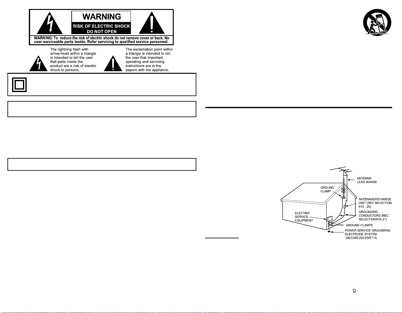
ADDITIONAL SAFETY INSTRUCTIONS
Outdoor Antenna Grounding
If an outside antenna or cable system is connected to the product, be sure the antenna
or cable system is grounded so as to provide some protection against voltage surges
and built-up static charges. Article 810 of the National Electrical Code, ANSI/NFPA 70,
provides information with regard to proper grounding of the mast and supporting structure, grounding of the lead-in wire to an antenna discharge unit, size of grounding
conductors, location of antenna-discharge unit, connection to grounding electrodes,
and requirements for the grounding electrode. See Figure.
EXAMPLE OF ANTENNA GROUNDING AS
PER (NEC) NATIONAL ELECTRICAL CODE
Installation
This unit Location
Adequate ventilation is essential to prevent internal component failure. Keep away from
areas of excessive heat or moisture.
To insure optimum color purity do not position magnetic equipment (motors, fans, other
speakers, etc.) nearby.
Optional External Equipment
The Video / Audio connection between components can be made with shielded video
and audio cables. For best performance, video cables should utilize 75 coaxial shielded
wire.
Page 3
Cables are available from your dealer or electronic supply house.
Before you purchase any cables, be sure you know what type of output and input connectors your various components require.
Also determine the length of cable you’ll need.
AC Power Supply Cord
CAUTION:
Do not place this unit upside down or in a vertical position.
Do not install and use this unit upside down.
Do not install and use this unit standing on its side.
To prevent electric shock, match wide blade of plug to wide slot of AC
outlet and fully insert. Do not use this (polarized) plug with a receptacle or other outlet unless the blade can be fully inserted to prevent
blade exposure.
Care and Cleaning
Turn Digital CATV Terminal Off
For Digital CATV Terminal, avoid excessive moisture and wipe dry.
Avoid bumping or scraping the Digital CATV Terminal.
Remote Control
For Remote Control, use a soft cloth dampened with water or a mild detergent solution.
Avoid excessive moisture and wipe dry.
Do not use benzene, thinner or other petroleum based products.
FCC STATEMENT
FCC INFORMATION
Radio Interference
This equipment has been tested and found to comply with the limit for a Class B Digital
Device in accordance with the specifications in Part 15 of FCC Rules. The rules are
designed to provide reasonable protection against radio and television interference in a
residential installation. This equipment generates, uses and can radiate radio frequency
energy and, if not installed and used in accordance with the instructions, may cause
harmful interference to radio communications. However, there is no guarantee that interference will not occur in a particular installation.
If this equipment does cause interference to radio or televisions reception (which you
can determine by turning the equipment off and on), try to correct the interference by
one or more of the following measures.
Reposition or relocate the receiving antenna for the radio or television that is “receiving” the interference.
Change the position of the Digital CATV Terminal with respect to the
radio or television equipment that is receiving interference.
Move the Digital CATV Terminal away from equipment receiving interference.
Plug the Digital CATV Terminal into a different wall outlet so the Digital CATV Terminal and equipment receiving the interference are on
different branch circuits.
If these measures do not eliminate interference, please consult your dealer or an experienced radio/television techni-cian for assistance.
FCC CAUTION:
Pursuant to 47CFR, Part 15.21 of the FCC rules, any changes or modifications to this Digital CATV Terminal not expressly approved by Matsushita
Electric Corporation of America could cause harmful interference and would
void the user’s authority to operate this device.
FCC Declaration of Conformity
PANASONIC CONSUMER ELECTRONICS COMPANY
Responsible party:
Matsushita Electric Corporation of America
One Panasonic Way
Secaucus, NJ 07094
U.S.A.
Telephone Number: 1-888-726-2377
(9 a.m.-9 p.m., Mon-Fri, EST)
(10 a.m.-7 p.m., Sat-Sun, EST) or
E-MAIL: consumerproducts@panasonic.com
This device complies with Part 15 of the FCC rules. Operation is subject to the
following two conditions: (1) this device may not cause harmful interference,
and (2) this device must accept any interference received,including interfer-
ence that may cause undesired operation.
This product incorporates copyright protection technology thatb is protected by U.S.
patents and other intellectual property rights.
Use of this copyright protection technology must be authorized by Macrovision Corporation, and is intended for home and other limited viewing uses only unless otherwise
autthorized by Macrovision. Reverse engineering or disassembly is prohibited.
U.S. Patents Nos. 4,631,603; 4,577,216; 4,819,098; 4,907,093; 6,381,747; and
6,516,132
Trademark acknowledgements
Manufactured under license from Dolby Laboratories.
“Dolby” and the double-D symbol are trademarks of Dolby Laboratories.
"TVPASS CARD" is a trademark of MOTOROLA CORPORATION.
All other trademarks are the property of the various trademark owners.
Page 4

Dear Panasonic Customer
Welcome to the Panasonic Family of customers. We hope that you have many years of enjoyment from your new Digital CATV
Terminal. To obtain maximum benefit from your set, please read these Instructions before making any adjustments, and retain
them for future reference.
For assistance, please call : your local cable operator
Front and Rear View of the Digital CATV Terminal
Front Panel
1
23
6
POWER
1
indicator(LED)
MENU Button
2
Remote control
3
signal present
indicator(LED)
11
5
12
4
1078
9
Lights when the unit is on.
Display the Main menu.
Flashes when an error-free signal is received
from the remote contorol.
Display
4
Channel Button
5
POWER Button
6
EXIT Button
7
8
SELECT Button
9
MESSAGE
10
indicator(LED)
Remote control
11
unit photoreceptor
USB Port
12
(Universal Serial Bus)
Button
Normally displays current channel number or
time of day; in the diagnostic mode,displays
diagnostic code.
Changes channel up or down.
Turn TZ-PCD3000 on/off.
Closes menus and show the previous screen.
Moves the cursor in menus and electronic program guide screens.
Selects menu options, purchases for Pay-PerView (PPV) events and tunes channels from
the electronic program guide.
Lights when a message is present.
Receives signal from the remote control
emitter lens window.
Use to connect a peripheral equipment to the
Digital CATV Terminal.
Page 5

Rear Panel
12
CABLE IN
CABLE OUT
CABLE IN
1
CABLE OUT
2
DIGIT AL AUDIO
3
COAX OUT
USB Port
4
(Universal Serial
Bus)
4
3
OUT2
R-AUDIO-L
R-AUDIO-L
OUT1
COAX
VIDEO
OUT
DIGITAL
AUDIO
OPT
VIDEO
S-VIDEO
8
7
Use to connect Cable Signal input from Cable
Service Provider.
Use to connect the Digital CATV Terminal output to your TV or VCR.
The COAXIAL S/PDIF connector is a digital output connection that carries Dolby Digital (up to
5.1ch) audio or PCM audio.
Use to connect a peripheral equipment to the
Digital CATV Terminal.
9
USB
SERIAL
IR
OUT
BLASTER
106
12
11
5
SWITCHED AC OUT
120V~60Hz 5A
AC IN
120V~60Hz
AC Switched
5
Outlet
AUDIO OUT
6
VIDEO OUT
7
S-VIDEO OUT
8
DIGIT AL AUDIO
9
OPT OUT
IR BLASTER
10
SERIAL port
11
AC Power Input
12
Use to connect the power cord plug of some
other component such as a TV.
(120 V AC, 60 Hz, 5 A)
Please use within specification.
Use to connect the Digital CATV Terminal audio output to your TV with stereo sound, or VCR
with stereo sound.
Note:
AUDIO OUT1 is for TV, and the volume is variable.
AUDIO OUT2 is for VCR, and the volume is fixed.
Use to connect the Digital CATV Terminal video
output to your TV or VCR.
Use to connect the Digital CATV Terminal Svideo output to your TV with S-VIDEO, or VCR
with S-VIDEO.
The OPTICAL S/PDIF connector is an optical
digital output connection that carries Dolby Digital (up to 5.1ch) audio or PCM audio.
When an IR BLASTER cable unit is connected
to this terminal, this terminal can output remote
control signals for recording images from a video
deck that is connected to the Digital CATV Terminal
This terminal can be used to send and receive
data between the Digital CATV Terminal and
other equipment.
(do not connect your PC to this SERIAL port.)
Use to connect the Digital CATV Terminal to an
AC electrical outlet with AC cord (included).
Page 6

Digital CATV Terminal connection to stereo TV and stereo VCR
Follow this diagram when connecting the Digital CATV Terminal to a stereo TV.
S-VIDEO
VIDEO
INPUT
L
AUDIO
R
Procedure
1 Connect S-VIDEO Cable from the S-VIDEO output jack on the Digital CATV Terminal to the S-VIDEO input jack on the TV or VCR.
Note: Connect either the S-VIDEO or video input/output as shown above.
S-VIDEO will provide better picture quallity.
2 Connect audio cables from the left and right audio output jacks on the Digital CATV Terminal to the left and right audio input jacks on
the TV or VCR.
Note: Additional equipment and cables shown are not supplied with this set.
Page 7

Digital CATV Terminal connection to TV and VCR
Follow this diagram when connecting the Digital CATV Terminal to a TV and VCR.
CABLE IN
CABLE OUT
OUT2
R-AUDIO-L
R-AUDIO-L
OUT1
COAX
VIDEO
OUT
DIGITAL
AUDIO
OPT
VIDEO
S-VIDEO
USB
SERIAL
IR
OUT
BLASTER
SWITCHED AC OUT
120V~60Hz 5A
AC IN
120V~60Hz
Procedure
Connect the CABLE OUT jack of the Digital CATV Terminal to the ANT IN jack of the VCR, and connect the ANT
OUT jack of the VCR to the ANT IN jack of the TV using 75 shielded cable.
Note:
Additional equipment and cables shown are not supplied with this set.
Page 8

Troubleshooting
Symptom
No power
No reception
No picture
No sound
Distorted picture
No color
The remote control is
not responding
Remedy
Check that the AC power plug is securely plugged into the power outlet.
Check that equipment is connected properly.
Check that the cable wire is connected properly.
Check that equipment is connected properly.
Check if the channel is available.
Make sure the TV power is turned on.
Make sure the proper input on the TV (TV/Video) is selected.
If your setup includes a VCR and/or stereo, make sure you have properly connected them to the Digital CATV Terminal unit.
Make sure your TV is tuned to the proper output channel (3 or 4).
Properly plug your television and Digital CATV Terminal unit into an electrical outlet.
Make sure all cables are properly connected.
Make sure the TV power is turned on.
If your setup includes a VCR and/or stereo, make sure you have properly connected them to the Digital CATV Terminal unit.
Make sure your TV is tuned to the proper output channel (3 or 4).
Make sure the volume is turned up.
Make sure the TV is not in “MUTE” mode.
Make sure all cables are properly connected.
Adjust the TV to channel 3 or 4.
Make sure the current TV program is broadcast in color.
Adjust the TV color controls.
Check that the batteries are installed with the correct polarities (+and -).
The batteries are depleted: Replace them with new ones.
Point the remote control unit at the remote control sensor and operate.
Operate the remote control unit at a distance of not more than 23 feet (7 meters) from the remote control sensor.
Remove any obstacles between the remote control unit and remote control sensor.
Make sure the remote control is in the proper component mode (i.e. CABLE, TV,VCR,AUDIO).
Panasonic Consumer Electronics Company ,
Division of Matsushita Electric Corporation of America
One Panasonic Way Secaucus New Jersey 07094
C
2004 Matsushita Electric Corporation of America. All Rights Reserved.
Printed in USA
S0704-0
 Loading...