

Page 1
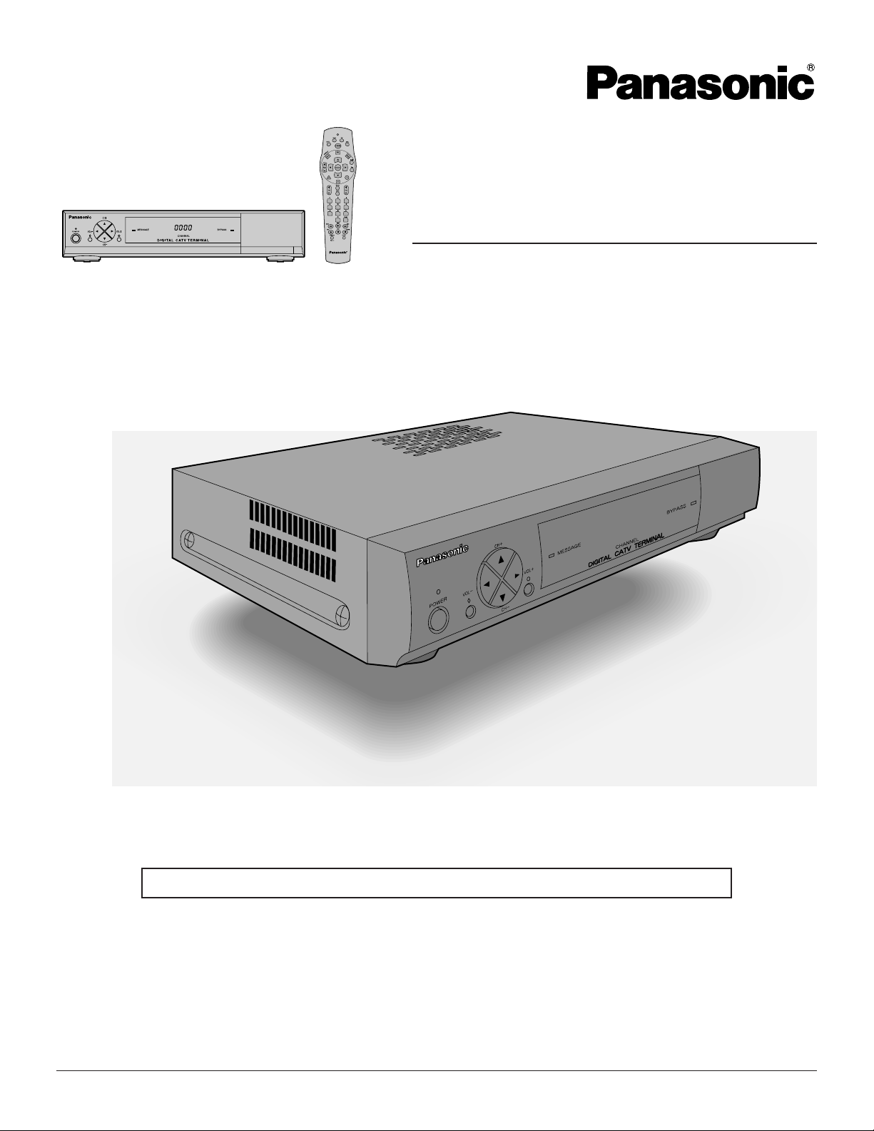
Digital CATV Terminal
Operating Instructions
Model No. TZ-PCD2000
For assistance, please call : your regional operator (installer)
Before connecting, operating or adjusting this product, please read these instructions completely. Save this manual for
future reference.
TQB2AA0369
1
Page 2
W ARNING
RISK OF ELECTRIC SHOCK
DO NOT OPEN
WARNING: To reduce the risk of electric shock do not remove cover or back. No
user-serviceable part s inside. Refer servicing to qualified service personnel.
The lightning flash with
arrow-head within a triangle
is intended to tell the user
that parts inside the
product are a risk of electric
shock to persons.
W ARNING: To prevent damage which may result in fire or shock hazard, do not expose this appliance to
rain or moisture.
The double insulation symbol ( a square within a square ) is intended to alert qualified
service personnel to use only identical replacement parts in this app aratus.
Note To CATV System Inst aller
This reminder is provided to call the CATV system installer’s attention to article 820-40 of the National Electric Code
that provides guidelines for proper grounding and, in particular , specifies that the cable ground shall be connected to
the grounding system of the building, as close to the point of cable entry as practical.
The exclamation point within
a triangle is intended to tell
the user that important
operating and servicing
instructions are in the
papers with the appliance.
Important Safety Instructions
1) Read these instructions.
2) Keep these instructions.
3) Heed all warnings.
4) Follow all instructions.
5) Do not use this apparatus near water.
6) Clean only with dry cloth.
7) Do not block any ventilation openings. Install in accordance with the manufacture’ s instructions.
8) Do not install near any heat sources such as radiators, heat registers, stoves, or other app aratus
(including amplifiers) that produce heat.
9) Do not defeat the safety purpose of the polarized or grounding-type plug. A polarized plug has two blades
with one wider than the other . A grounding-type plug has two blades and a third grounding prong. The wide
blade or the third prong are provided for your safety . If the provided plug does not fit into your outlet,
consult an electrician for replacement of the obsolete outlet.
10)Protect the power cord from being walked on or pinched particularly at plugs, convenience recept acles, and
the point where they exit from the apparatus.
1 1)Only use attachments/accessories specified by the manufacturer .
12)Use only with the cart, stand, tripod, bracket, or t able specified by the manufacturer,
or sold with the apparatus. When a cart is used, use caution when moving the cart /
apparatus combination to avoid injury from tip-over.
13)Unplug this apparatus during lightning storms or when unused for long periods of time.
14)Refer all servicing to qualified service personnel. Servicing is required when the apparatus has been damaged in any way , such as power-supply cord or plug is damaged, liquid has been spilled or object s have
fallen into the apparatus, the apparatus has been exposed to rain or moisture, does not operate normally, or
has been dropped.
2
Page 3

Additional Instructions
Additional Instructions
l Power Sources
This product shall be operated only from the type of power source indicated on the marking label. If you are not sure
of the type of power supply to your home, consult your Cable operator or Digital CATV Terminal installer or local
power company .
l Overloading
Do not overload wall outlets and extension cords as this can result in a risk of fire or electric shock.
l Object and Liquid Entry
Never push objects of any kind into this product through openings as they may touch dangerous voltage point s or
short-out parts that could result in a fire or electric shock. Never spill liquid of any kind on the product.
l Servicing
Do not attempt to service this product yourself as opening or removing covers may expose you to dangerous voltage or other hazards. Refer all servicing to qualified service personnel.
l Replacement Parts
When replacement parts are required, be sure the service technician has used replacement part s specified by the
manufacturer . Unauthorized substitutions may result in fire,
electric shock or other hazards.
l Safety Check
Upon completion of any service or repairs to this product, ask the service technician to perform safety checks to
determine that the product is in proper operating condition.
l Damage Requiring Service
Unplug this product from the wall outlet and refer servicing to qualified service personnel under the following conditions:
a. When the power-supply cord or plug is damaged.
b. If liquid has been spilled, or objects have fallen into the product.
c. If the product does not operate normally by following the operating instructions. Adjust only those controls that are
covered by the operating instructions as an improper adjustment of other controls may result in damage and will
often require extensive work by a qualified technician to restore the product to its normal operation.
d. If the product has been dropped or the cabinet has been damaged.
e. When the product exhibits a distinct change in performance - this indicates a need for service.
f. If the product has been exposed to rain or water.
3
Page 4
Additional Instructions
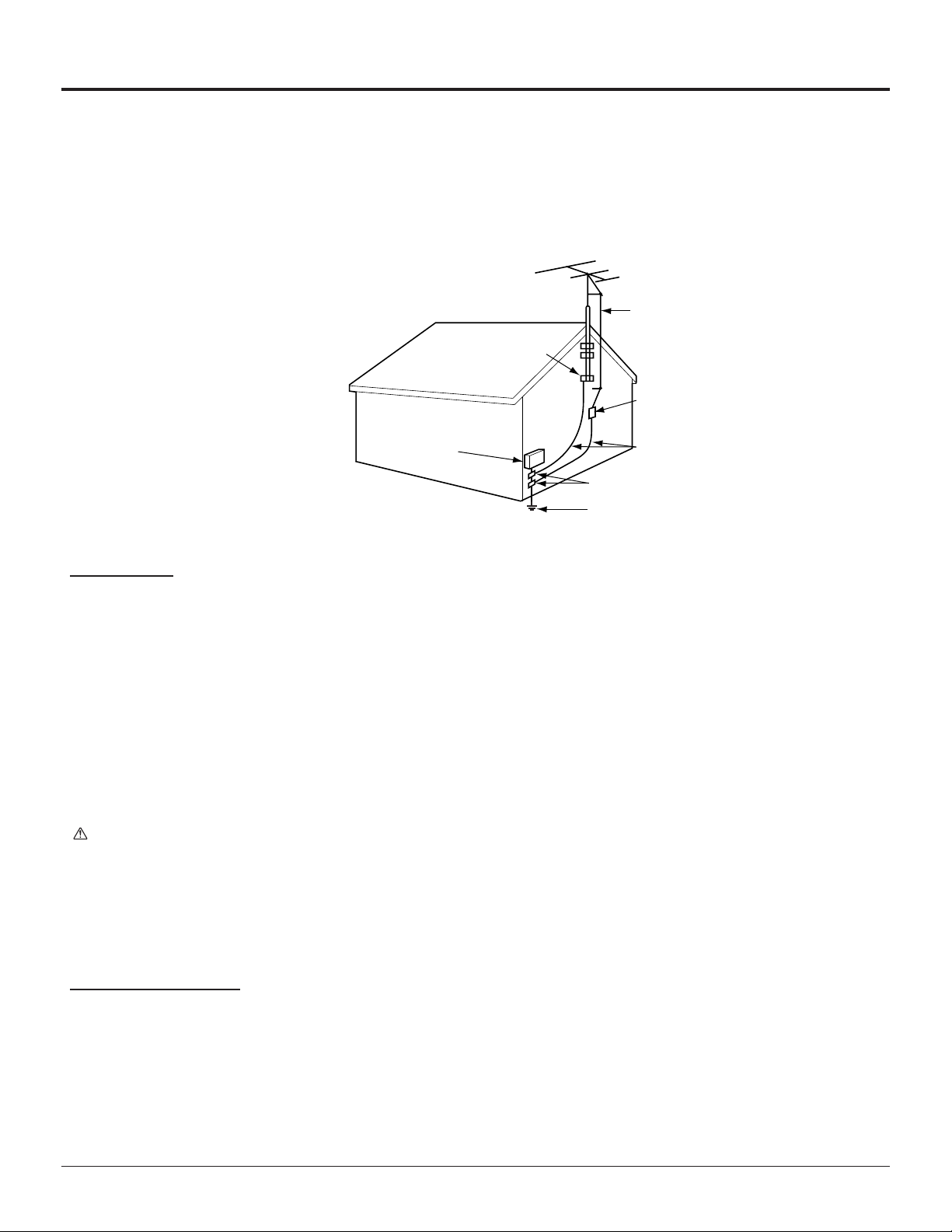
l Outdoor Antenna Grounding
If an outside antenna or cable system is connected to the product, be sure the antenna or cable system is grounded
so as to provide some protection against voltage surges and built-up static charges. Article 810 of the National
Electrical Code, ANSI/NFPA 70, provides information with regard to proper grounding of the mast and supporting
structure, grounding of the lead-in wire to an antenna discharge unit, size of grounding conductors, location of
antenna-discharge unit, connection to grounding electrodes, and requirements for the grounding electrode. See
Figure.
EXAMPLE OF ANTENNA GROUNDING AS PER
(NEC) NATIONAL ELECTRICAL CODE
GROUND
CLAMP
ELECTRIC
SERVICE
EQUIPMENT
ANTENNA
LEAD-IN WIRE
ANTENNA DISCHARGE
UNIT (NEC SELECTION
810 - 20)
GROUNDING
CONDUCTORS (NEC
SELECTION 810 - 21)
GROUND CLAMPS
POWER SERVICE GROUNDING
ELECTRODE SYSTEM
(NEC ART 250,PART H)
Installation
This unit Location
Adequate ventilation is essential to prevent internal component failure. Keep away from areas of excessive heat or
moisture.
To insure optimum color purity do not position magnetic equipment (motors, fans, other speakers, etc.) nearby.
Optional External Equipment
The Video / Audio connection between components can be made with shielded video and audio cables. For best
performance, video cables should utilize 75 Ω coaxial shielded wire. Cables are available from your dealer or electronic supply house.
Before you purchase any cables, be sure you know what type of output and input connectors your various components require.
Also determine the length of cable you’ll need.
AC Power Supply Cord
CAUTION: To prevent electric shock, match wide blade of plug to wide slot of AC outlet and fully insert. Do not use
this (polarized) plug with a receptacle or other outlet unless the blade can be fully inserted to prevent
blade exposure.
Do not place this unit upside down or in a vertical position.
Do not install and use this unit upside down.
Do not install and use this unit standing on its side.
Care and Cleaning
Turn Digital CATV Terminal Off
For Digital CATV T erminal, avoid excessive moisture and wipe dry.
Avoid bumping or scraping the Digital CATV Terminal.
Remote Control
For Remote Control, use a soft cloth dampened with water or a mild detergent solution. A void excessive moisture and
wipe dry .
Do not use benzene, thinner or other petroleum based products.
4
Page 5

FCC STATEMENT
FCC INFORMA TION
Your Digital CATV Terminal is registered with the Federal Communication Commission and is in compliance with
CFR47, Parts 15b, FCC Rules and Regulations.
Radio Interference
This equipment has been tested and found to comply with the limit for a Class B Digital Device in accordance with the
specifications in Part 15 of FCC Rules. The rules are designed to provide reasonable protection against radio and
television interference in a residential installation. This equipment generates, uses and can radiate radio frequency
energy and, if not installed and used in accordance with the instructions, may cause harmful interference to radio
communications. However, there is no guarantee that interference will not occur in a particular inst allation.
If this equipment does cause interference to radio or televisions reception (which you can determine by turning the
equipment off and on), try to correct the interference by one or more of the following measures.
l Reposition or relocate the receiving antenna for the radio or television that is “receiving” the interference.
l Change the position of the Digital CATV Terminal with respect to the radio or television equipment that is receiving
interference.
l Move the Digital CATV Terminal away from equipment receiving interference.
l Plug the Digital CATV Terminal into a different wall outlet so the Digital CATV Terminal and equipment receiving the
interference are on different branch circuits.
If these measures do not eliminate interference, please consult your dealer or an experienced radio/television technician for assistance.
FCC CAUTION:
Pursuant to 47CFR, Part 15.21 of the FCC rules, any changes or
modifications to this Digital CATV Terminal not expressly approved by
Matsushit a Electric Corporation of America could cause harmful
interference and would void the user’s authority to operate this device.
FCC Declaration of Conformity
PANASONIC CONSUMER ELECTRONICS COMPANY
Responsible party:
Matsushita Electric Corporation of America
One Panasonic Way
Secaucus, NJ 07094
U.S.A.
T elephone Number: 201-392-4430
(8 a.m.-10 p.m., Mon-Fri, EST)
(10 a.m.-10 p.m., Sat-Sun, EST) OR
E-MAIL: CONSUMER PRODUCTS@P ANASONIC.COM
This device complies with Part 15 of the FCC rules. Operation is subject to the following two conditions: (1) this device may not cause harmful interference, and (2) this device must accept any interference received, including interference that may cause undesired operation.
5
Page 6

Dear Panasonic Customer
Welcome to the Panasonic Family of customers. We hope that you have many years of
enjoyment from your new Digital CATV Terminal. To obtain maximum benefit from your
set, please read these Instructions before making any adjustments, and retain them for
future reference.
Retain your purchase receipt also, and note down the model number and serial
number of your set in the space provided on the rear cover of these instructions.
For assistance, please call : your regional operator (installer)
Table of Contents
Important Safety Instructions................................................................................................................................ 2
FCC STATEMENT.................................................................................................................. .................................. 5
Installation .............................................................................................................................................................. 7
ACCESSORIES ........................................................................................................................................ 7
Remote Control battery installation .............. ............................................................................................. 7
Front and Rear View of the Digital CATV Terminal .................................................................................... 8
Cable connection....................................................................................................................................... 10
Digital CATV Terminal connection to stereo TV and stereo VCR ............................................................... 10
Digital CATV Terminal connection to TV and VCR..................................................................................... 11
Digital CATV Terminal connection to component with Digital Audio Input jack........................................... 12
Connect AC Power Cord ........................................................................................................................... 12
Power ON/OFF ......................................................................................................................................... 13
Changing the TV input source (Panasonic TV models) ............................................................................. 13
Remote Control ...................................................................................................................................................... 14
Programming the Remote Control ........................................................................................................................ 17
Troubleshooting ..................................................................................................................................................... 25
Specifications ......................................................................................................................................................... 26
Trademark acknowledgements
l “VCR Commander” is trademark of Scientific-Atlanta, Inc.
l “Dolby” and “AC-3” are trademarks of Dolby Laboratories.
All other trademarks are the property of the various trademark owners.
6
Page 7
Installation
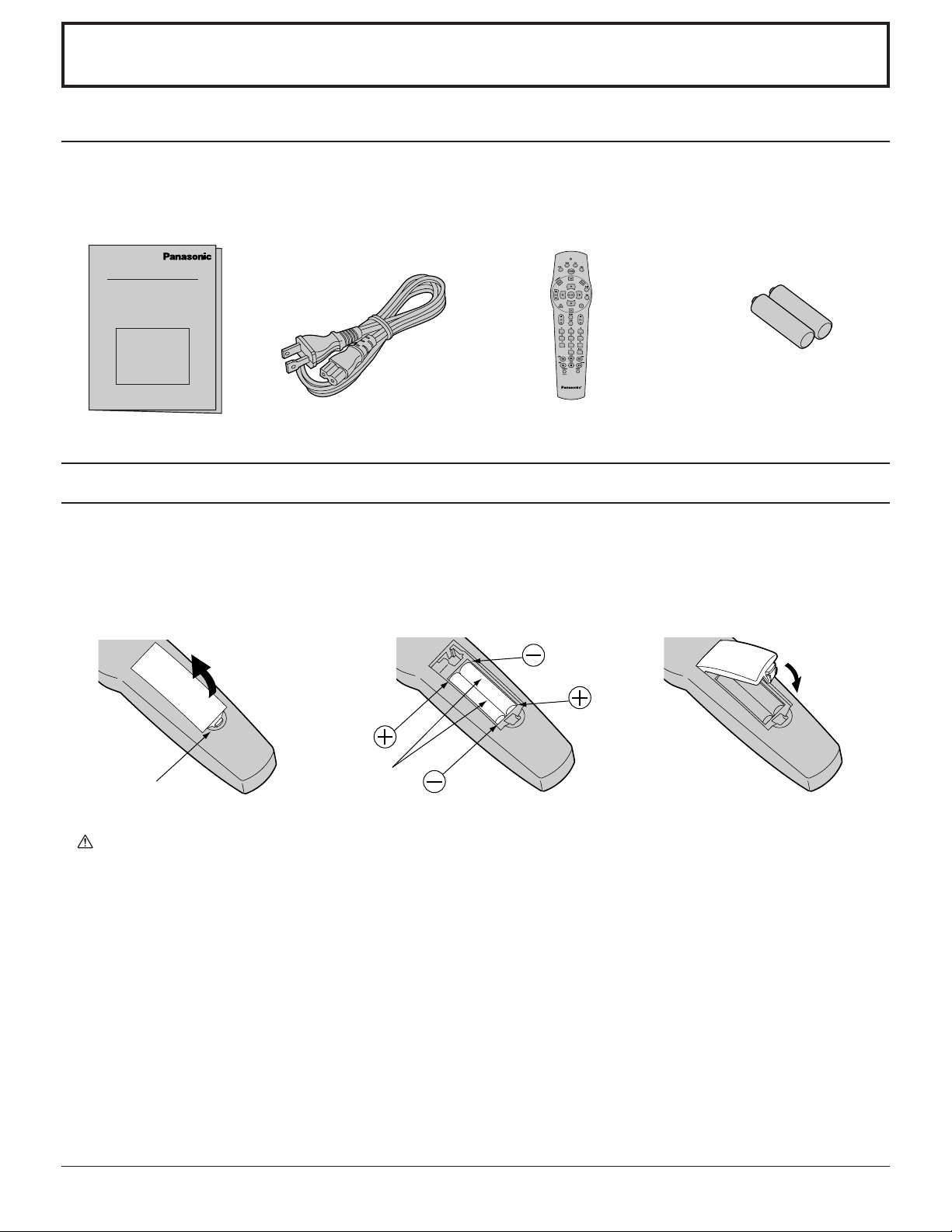
ACCESSORIES
Check the accessories before installations.
l Operating
Instruction book
Remote Control battery installation
l AC Power Cord l Remote Control
Unit
l Battery for the Remote
Control Unit
(2×AA (IEC R6) size)
Requires two AA batteries.
1.Push the section marked with
an arrow while lifting the cover
up to open it.
2.Install the batteries as shown in
the battery compartment.
(Polarity + or - must match the
markings in the compartment).
Two A A size
3.Close the cover by inserting the
top end first.
Precaution on battery use
Incorrect installation can cause battery leakage and corrosion that will damage the remote control transmitter .
Observe the following precautions:
1. Batteries should always be replaced as a pair. Always use new batteries when replacing the old set.
2. Do not combine a used battery with a new one.
3. Do not mix battery types (example: “Zinc Carbon” with “Alkaline” ).
4. Do not attempt to charge, short-circuit, disassemble, heat or burn used batteries.
5. Battery replacement is necessary when remote control acts sporadically or stops operating this unit.
Helpful Hint:
Whenever you remove the batteries, you may need to reset the remote control infrared codes. We recommend
that you record the code on page17-24, prior to setting up the remote.
7
Page 8
Installation
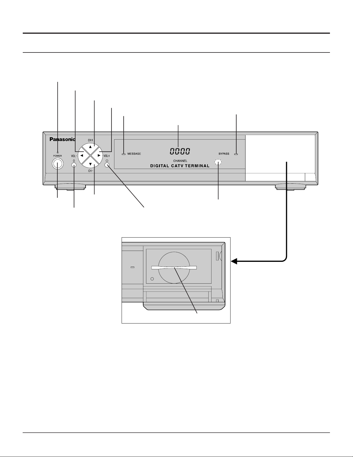
Front and Rear View of the Digital CATV Terminal
Front Panel
POWER indicator(LED)
V olume - Button
Channel + Button
V olume + Button
MESSAGE indicator(LED)
Display
BYP ASS indicator(LED)
Power Button
POWER Turns the Digital CATV Terminal Power On or Off.
Channel - Button
Factory use only
Factory use only
Card Slot
Remote control signal
receptor
Door
Pull the door toward you to open it.
VOL +- Select Volume Up or Down
CH +- Select Channel Up or Down
MESSAGE Message indicator
BYP ASS Bypass indicator
Card Slot This is currently not being used. It is reserved for future applications as the place for cards to be
inserted.
8
Page 9
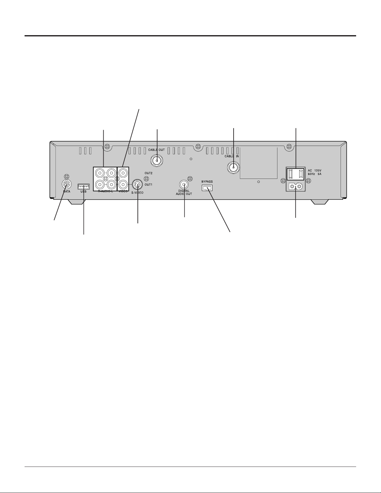
Rear Panel
Installation
VIDEO jacks
DA TA Port
CABLE IN
CABLE OUT
VIDEO
S-VIDEO
AUDIO jacks
USB(Universal
Serial Bus) Port
Use to connect Cable Signal from Cable Service Provider.
Use to connect the Digital CATV Terminal to your TV or VCR.
Use to connect the Digital CATV Terminal to your TV or VCR.
Use to connect the Digital CATV T erminal to your TV with S-VIDEO, or VCR with S-VIDEO.
S-VIDEO jack
CABLE OUT jack CABLE IN jack AC Switched Outlet
DIGIT AL AUDIO OUT
BYP ASS option
AC Power Input
AUDIO
DIGIT AL AUDIO
OUT
DA TA
USB (Universal
Serial Bus)
BYP ASS
AC Power Input
AC Switched
Outlet
Use to connect the Digital CATV Terminal to your TV with stereo sound, or VCR with stereo
sound.
Use to connect the Digital CATV T erminal to a Dolby Digital AC-3 decoder .
Use to connect the Digital CATV Terminal to the VCR CommanderTM module or similar
equipment.See the VCR CommanderTM User’s Guide for more information.
Use to connect the Digital CATV T erminal to external equipment.
Use to connect a RF Bypass Module (optional) to byp ass the Digital CATV Terminal when
watching regular cable TV broadcasts.
Use to connect the Digital CATV T erminal to an AC electrical outlet with AC cord (included).
Use to connect the power cord plug of some other component such as a TV.
(120 V AC, 60 Hz, 5 A)
9
Page 10

Installation
Cable connection
Connect the cable wire to the CABLE IN jack on the rear panel of the Digit al CATV Terminal.
Incoming signal from the Cable Service Provider
Unplug the AC power cord and disconnect
all cables attached to the Digital CATV Terminal.
Digital CATV Terminal connection to stereo TV and stereo VCR
Follow this diagram when connecting the Digital CATV Terminal to a stereo TV and stereo VCR.
VCR or S-VCR
TV or S-VCR
TV
Procedure
1 Connect S-VIDEO Cable from the S-VIDEO output jack on the Digit al CATV Terminal to the S-VIDEO input jack on
the TV or S-VCR.
Note:Connect either the S-VIDEO or video input/output as shown above.
l S-VIDEO will provide better picture quallity.
2 Connect audio cables from the lef t and right audio output jacks on the Digital CATV Terminal to the left and right
audio input jacks on the TV or VCR (S-VCR).
Note:
l Additional equipment and cables shown are not supplied with this set.
10
Page 11

Installation
Digital CATV Terminal connection to TV and VCR
Follow this diagram when connecting the Digital CATV Terminal to a TV and VCR.
TV
VCR or S-VCR
Procedure
l Connect the CABLE OUT jack of the Digital CATV Terminal to the ANT IN jack of the VCR, and connect the ANT
OUT jack of the VCR to the ANT IN jack of the TV using 75 Ω shielded cable.
Connecting a non-cable ready TV
Jumper Cable
VHF Matching
Transformer
TV Set UHF Antenna
Terminals
Note:
l Additional equipment and cables shown are not supplied with this set.
TV Set VHF Antenna Terminals
Rear of Non Cable-Ready TV
11
Page 12

Installation
Digital CATV Terminal connection to component with Digital Audio Input jack
Follow this diagram to connect the Digital CATV Terminal to a component with a Digital Audio Input jack.
Dolby Digital
AC-3 decoder
or
Procedure
1 Connect the Digit al Audio Cable from the Digital Audio Out jack on the Digital CATV Terminal to the Digital Audio
Input jack on the component with the Digital Audio Input jack.
2 Connect the TV or other component while referring to page 10.
6-Channel Amplifier
& Speakers
TV
Note:
l If using a Dolby Digital AC-3 decoder, you can enjoy Dolby Digital (AC-3) 5.1 channel surround sound.
l Additional equipment and cables shown are not supplied with this set.
Connect AC Power Cord
AC Power Cord
AC Power Cord
Procedure
l Connect the AC power cord to the AC power input at the rear of the Digital CATV Terminal, and plug the AC power
cord into a grounded outlet.
12
Page 13

Power ON/OFF
Installation
Push the POWER button on this unit to turn the set on
POWER-ON
Power Indicator: Green
Power Indicator
1
Press POWER once more to turn off.
Power Indicator: Indicator not illuminated
( Please understand the Digital CATV Terminal is not updated
when you plug off from AC outlet.)
<When using the remote control>
1
Press the Remote Control CBL mode button
2
Press the POWER button.
2
Changing the TV input source (Panasonic TV models)
Procedure
1
Press the TV mode button.
2
1
2
Press the POWER button to turn on the power for the TV.
3
Press the TV/VCR button to select the picture from the Digital
CATV T erminal. If the connection is via the CABLE OUT jack as
shown on page 11, use the CH UP/DOWN button on the TV to
set the channel to the VCR output channel (channel 3 or 4).
3
Note:
l If using a non-Panasonic brand TV, make the selection directly
at the TV itself, or use the TV’s remote control to make the
setting as described on page 17.
l Some Panasonic brand TVs may have different remote control
codes,so that these TVs cannot be operated as described
above even though they are Panasonic-brand TVs. In such
cases, make the selection directly at the TV itself, or use the
TV’s remote control to make the setting as described on page
17.
l The default remote control settings do not allow TV and VCR
CH UP/DOWN settings to be made.Y ou first need to clear the
channel lock as described on page 20.
13
Page 14

Remote Control
CBL, TV, VCR, AUX
Press to select remote operation.
POWER
Press to turn ON and OFF.
Press to move through interactive
screen choices.
SELECT
Press to choose interactive screen
item.
Page
Press to display Next/Previous
screen.
Menu
Press to display Settings menu.
Info
Press to display channel information.
Guide
Press to display interactive
program guide.
Exit
Press to hide interactive screen.
A, B, C
On-Screen decision buttons
CH
Press to select channel Up/Down
Mute
Press to turn sound off.
Last
Press to return to last channel
viewed.
Fav
Press to view favorite channels.
VOL
Press to adjust volume.
0-9
Press to enter channel and
personal identification
numbers(PIN).
14
Page 15

Remote Control Function Key Chart
Key Component Function
Remote Control
ALL COMPONENTS
ALL COMPONENTS
CBL
CBL
TV
VCR
CBL
TV
VCR
AUX
CBL, TV
CBL
CBL, TV
Component mode selection for
remote control
Turn components On and OFF
Interactive program guide
Channel information
On screen display
Program
Settings menu
ACTION
Menu
Program mode
Exit Menus
View favorite channels
Up,Down,Left and Right navigation
CBL
CBL
CBL
CBL, TV, VCR
CBL, TV, VCR
AUX
CBL, TV, VCR
CBL, TV
The description of functions for each of the components in the table above apply when the factory
default code settings are in place. The factory default code settings are as follows:
TV:Panasonic brand TV (code: 0250)
VCR:Panasonic-brand VCR (code: 1062)
AUX:Panasonic-brand CD Player (code: 0303)
Select
Display Next/Previous screen
On-Screen decision buttons
Volume up/down
Channel up/down
Skip forward/rewind
Mute audio
Return to last channel viewed
15
Page 16

Remote Control
Key Component Function
Remote Control Function Key Chart
CBL, TV, VCR
VCR
AUX
CBL
TV
VCR
AUX
CBL
TV
VCR
AUX
CBL
TV
VCR
AUX
CBL
TV
VCR
Select channel
Select code
Channel enter
Disc
VOD rewind
Punch to VCR
Rewind
Fast search rev
VOD play
Punch to VCR
Play
Play
VOD fast fwd
Punch to VCR
Fast forward
Fast search fwd
VOD record
Punch to VCR
record
CBL
TV
VCR
AUX
CBL
TV
VCR
AUX
CBL
TV
VCR
AUX
ALL COMPONENTS
The description of functions for each of the components in the table above apply when the factory
default code settings are in place. The factory default code settings are as follows:
TV:Panasonic brand TV (code: 0250)
VCR:Panasonic-brand VCR (code: 1062)
AUX:Panasonic-brand CD Player (code: 0303)
VOD stop
Punch to VCR
Stop
Stop
VOD pause
Punch to VCR
Pause
Pause
BYPASS
TV/VIDEO
TV/VCR
SIDE A-B
SETUP
16
Page 17

Programming the Remote Control
The Universal Remote Control can be programmed to operate many manufacturers’components using the
component function buttons for TV, VCR, or AUX. Follow the procedures for programming your Remote Control
with and without codes for the component. Determine the manufacturer of the component and look in the table for
the code.
n Programming for TV operation
Use the following procedure to program the TV remote control code. At the time of
shipment from the factory , this is set to Panasonic-brand TVs (code:0250).
Use the following procedure to program the TV remote control code.
AUX button
VCR button
LED
TV button
1.Select the Setup Code for your TV by referring to the tables on pages 21 to 24. If you
cannot find the right Setup Code, refer to “Programming Without Code” on page 18.
2.Press the TV button, and then press the Setup button and hold for 3 seconds (until
the visible LED blinks twice).
3.Use the numeric buttons on the remote control to enter a 4-digit Setup Code. When
programming is complete, the LED on the remote control will flash twice.
n Programming for VCR operation
You can use the remote control for the Digital CATV Terminal to operate your VCR,DVD
player. However, a VCR Commander Module (not included) is requred in order to
program your VCR for recording. If you are not using a VCR Commander Module, you
will need to make the programming operations directly at the VCR. For details, refer to
the User’s Guide which is supplied with the VCR Commander package. At the time of
shipment from the factory , the code is set to Panasonic-brand VCRs (code: 1062).
Setup button
Numeric buttons
Use the following procedure to program the VCR or DVD player remote control code.
1.Select the Setup Code for your VCR by referring to the tables on pages 21 to 24. If you
cannot find the right Setup Code, refer to “Programming Without Code” on page 18.
2.Press the VCR button, and then press the Setup button and hold for 3 seconds (until
the visible LED blinks twice).
3.Use the numeric buttons on the remote control to enter a 4-digit Setup Code. When
programming is complete, the LED on the remote control will flash twice.
n Programming for AUX (other component) operation
You can use the remote control for the Digital CATV Terminal to operate a CD player,
DVD player, Audio Amplifier , Miscellaneous Audio component, Audio Amplifiers and
Tuners, Home Automation equipment or Cable Converter. At the time of shipment from
the factory , the code is set to Panasonic-brand CD player (code: 0303).
Use the following procedure to program the desired component.
1.Select the Setup Code for the desired component by referring to the tables on pages
21 to 24. If you cannot find the right Setup Code, refer to “Programming Without
Code” on page 18.
2.Press the AUX button, and then press the Setup button and hold for 3 seconds (until
the visible LED blinks twice).
3.Use the numeric buttons on the remote control to enter a 4-digit Setup Code. When
programming is complete, the LED on the remote control will flash twice.
Unsuccessful Code
If the component does not operate with the remote control, repeat the procedure using
another code. (Some brands have multiple codes.)
If you enter an incorrect Code, or if no button is pressed for 10 seconds or
more, the program will be canceled.
17
Page 18

Programming the Remote Control
n Programming Without Code
If you cannot find the right Code, you can call up all Codes one after the other to
search for a Code.
1.Turn on the power for the Component to be programmed.
2.Press the mode button (TV, VCR or AUX) for the component to be programmed,
and then press the Setup button and hold for 3 seconds (until the visible LED blinks
twice).
POWER button
AUX button
VCR button
LED
TV button
3.Use the numeric buttons on the remote control to enter “991”. Af ter this number is
entered, the LED on the remote control will flash twice.
4.Press the POWER button. (A remote control signal will be transmitted.)
5.If the component turns off, go to step 6. If the component remains on, press the
mode button (TV, VCR or AUX), and then repeat step 4. (Repeat this step until the
right Code is found.)
6.Press the Setup button to register the Code. When programming is complete, the
LED on the remote control will flash twice.
n Identifying programmed Codes
If you would like to know what Code has been programmed, you can find out by
observing the flashing pattern of the remote control LED.
Setup button
Numeric buttons
1.Press the mode button (TV, VCR or AUX) for the component that you would like to
find out the Code for , and then press the Setup button and hold for 3 seconds (until
the visible LED blinks twice).
2.Use the numeric buttons on the remote control to enter “990”. After this number is
entered, the LED on the remote control will flash twice.
3.When a “1” is then entered using the numeric buttons, the remote control LED will
flash. The number of times it flashes corresponds to the first digit of the Code. For
example, if the LED flashes five times, the first digit of the Code is 5.
4.When a “2” is then entered using the numeric buttons, the remote control LED will
flash. The number of times it flashes corresponds to the second digit of the Code.
5.When a “3” is then entered using the numeric buttons, the remote control LED will
flash. The number of times it flashes corresponds to the third digit of the Code.
6.When a “4” is then entered using the numeric buttons, the remote control LED will
flash. The number of times it flashes corresponds to the fourth digit of the Code.
7.Write the code numbers for your components in the sp ace provided below. This will
serve as a reference when you need to program your remote control.
Name of component
TV
VCR
()
()
VCR , DVD player
TV
18
AUX
()
Page 19

AUX button
VCR button
LED
TV button
CBL button
Programming the Remote Control
n Programming for volume control
The volume adjustment function can be locked so that regardless of whether CBL, TV
or VCR mode is active, the volume is adjusted for only one of the modes. (Refer to
the
table below .)
The default setting is TV. When the setting is AUX mode, you can adjust the volume
for the AUX component at all times, even if some other mode is currently active.
Physical Mode Keys
V olume
Locked to:
TV
VCR
CBL
AUX
Setting method
1.Press the Setup button and hold for 3 seconds (until the visible LED blinks twice).
2.Use the numeric buttons on the remote control to enter “993”. After this number is
entered, the LED on the remote control will flash twice.
3.Press the button for the mode that you would like to lock the volume adjustment for.
When the setting is complete, the LED on the remote control will flash twice.
Canceling the setting
1.Press the Setup button and hold for 3 seconds (until the visible LED blinks twice).
2.Use the numeric buttons on the remote control to enter “993”. After this number is
entered, the LED on the remote control will flash twice.
3.Press the VOL + button. When the setting is canceled, the LED on the remote
control will flash four times.
TV
TV TV TV
VCR VCR VCR AUX
CBL CBL CBL
VCR
CBL
AUX
AUX
AUX
AUXAUXAUXAUX
Setup button
Numeric buttons
VOL + button
Note:
l In the case of Mode Reassignment, the operation will be as shown in the table
below . See below for details on Mode Reassignment.
Physical Mode Keys
V olume
Locked to:
TV
VCR
CBL
AUX
TV
TV TV2 TV
TV2 TV2 TV2 AUX
CBL TV2 CBL
VCR
Mode Reassigned to:
TV2
CBL
AUX
AUX
AUX
AUXAUXTV2AUX
n Mode Reassignment
You can assign the Code for setting a certain mode (TV , VCR or AUX) to use as the
Code for setting some other mode.
(Example) Assigning the button setting Code for TV mode to the button for VCR mode
1.Press the Setup button and hold for 3 seconds (until the visible LED blinks twice).
2.Use the numeric buttons on the remote control to enter “992”. After this number is
entered, the LED on the remote control will flash twice.
3.Press the TV button.
4.Press the VCR button. When the setting is complete, the LED on the remote control
will flash twice. Then you can use second TV (which has other Remote Code)
instead of VCR.
Note:
l The Code for CBL mode cannot be assigned to any other mode. Furthermore, no
other Code can be assigned to CBL mode.
19
Page 20

Programming the Remote Control
n Changing button functions
The functions of the remote control buttons can be assigned to other buttons.
Setting method
(Example) Assigning the function of the POWER button in TV mode to the Exit button
in VCR mode
1.Press the Setup button and hold for 3 seconds (until the visible LED blinks twice).
POWER button
AUX button
VCR button
LED
TV button
Exit
button
2.Use the numeric buttons on the remote control to enter “994”. After this number is
entered, the LED on the remote control will flash twice.
3.Press the TV mode button, and then press the POWER button.
4.Press the VCR button, and then press the Exit button. When programming is complete, the LED on the remote control will flash twice.
Canceling the setting
1.Press the Setup button and hold for 3 seconds (until the visible LED blinks twice).
2.Use the numeric buttons on the remote control to enter “994”. After this number is
entered, the LED on the remote control will flash twice.
3.Press the Mode button twice. When programming is complete, the LED on the
remote control will flash twice.
n Channel lock
The Digital CATV T erminal lets you lock the channel selection (0~9 buttons, CH Up/
Down buttons, Last button) functions. The following procedure can be used to set
whether channel selection is locked or not.
Setup button
Numeric buttons
CH +- button
Clearing the lock
1.Press the Setup button and hold for 3 seconds (until the visible LED blinks twice).
2.Use the numeric buttons on the remote control to enter “973”. After this number is
entered, the LED on the remote control will flash twice.
3.Press the CH - button. When programming is complete, the LED on the remote
control will flash twice.
Setting the lock
1.Press the Setup button and hold for 3 seconds (until the visible LED blinks twice).
2.Use the numeric buttons on the remote control to enter “973”. After this number is
entered, the LED on the remote control will flash twice.
3.Press the CH + button. When programming is complete, the LED on the remote
control will flash twice.
n Reset
Y ou can reset any remote control settings which have been changed.
The settings can be reset in either of two ways.
Operation setting reset
This resets all remote control settings to their factory default values, except for Codes
set in TV, VCR and AUX modes.
1.Press the Setup button and hold for 3 seconds (until the visible LED blinks twice).
2.Use the numeric buttons on the remote control to enter “980”. When resetting is
complete, the LED on the remote control will flash four times.
20
Factory default reset
This resets all remote control settings to the factory defaults.
1.Press the Setup button and hold for 3 seconds (until the visible LED blinks twice).
2.Use the numeric buttons on the remote control to enter “977”. When resetting is
complete, the LED on the remote control will flash four times.
Page 21

Programming the Remote Control
Component Codes
The Universal Remote Control is capable of operating many component brands after entering a code.
Some components may not operate. The Universal Remote Control does not control all features in all models.
Codes for TVs (for TV mode)
Manufacturer List
Manufacturer Set Up No. Manufacturer Set Up No.
AOC 0030, 0019
Admiral 0093, 0463
Aiko 0092
Akai 0030
Alaron 0179
Ambassador 0177
America Action 0180
Ampro 0751
Anam 0180
Anam National 0055
Audiovox 0451, 0180, 0092
Baysonic 0180
Belcor 0019
Bell & Howell 0154, 0016
Bradford 0180
Brockwood 0019
Broksonic 0236, 0463
CXC 0180
Candle 0030, 0056
Carnivale 0030
Carver 0054
Celebrity 0000
Cineral 0451, 0092
Citizen 0060, 0030, 0056, 0092, 0039
Concerto 0056
Contec 0180
Craig 0180
Crosley 0054
Crown 0180, 0039
Curtis Mathes 0047, 1147, 1347, 0054, 0154, 0051,
0451, 0093, 0060, 0030, 0056, 0145,
0016, 0039, 0166, 0466
Daewoo 0451, 0019, 0092, 0039
Daytron 0019
Denon 0145
Dumont 0017, 0019
Dwin 0720, 0774
Electroband 0000
Emerson 0154, 0236, 0463, 0180, 0178, 0179,
0019, 0282, 0039, 0177
Envision 0030
Fisher 0154
Fujitsu 0179, 0683
Funai 0180, 0179, 0171
Futuretech 0180
GE 0047, 1 147, 1347, 0051, 0451, 0093,
0178, 0021, 0282, 0135, 0055
Gibralter 0017, 0030, 0019
GoldStar 0030, 0178, 0056, 0019
Gradiente 0053, 0056
Grunpy 0180, 0179
Hallmark 0178
Harley Davidson 0179
Harman/Kardon 0054
Harvard 0180
Hitachi 0056, 0145, 0016, 0151
Infinity 0054
Inteq 0017
JBL 0054
JCB 0000
JVC 0053
KEC 0180
KTV 0180, 0030, 0039
Kenwood 0030, 0019
LG 0056
LXI 0047, 0054, 0154, 0156, 0178
Logik 0016
Luxman 0056
MGA 0150, 0030, 0178, 0019
MTC 0060, 0030, 0056, 0019
Magnavox 0054, 1254, 0030, 0179
Majestic 0016
Marantz 0054, 0030
Matsushita 0250
Megatron 0178, 0145
Memorex 0154, 0250, 0463, 0150, 0178, 0056,
0016
Midland 0047, 0017, 0051, 0135, 0039
Minutz 0021
Mitsubishi 0093, 0150, 0178, 0019
Motorola 0093, 0055
Multitech 0180
NAD 0156, 0178, 0166
NEC 0030, 0056, 0019
NTC 0092
Nikko 0030, 0178, 0092
Onwa 0180
Optimus 0154, 0250, 0166
Optonica 0093, 0165
Orion 0236, 0463, 0179
Panasonic 0051, 0250, 0055
Penney 0047, 1347, 0156, 0051, 0060, 0030,
0178, 0021, 0056, 0019, 0135, 0039
Philco 0054, 0463, 0030, 0145, 0019
Philips 0054
Pilot 0030, 0019, 0039
Pioneer 0166
Portland 0019, 0092, 0039
Prism 0051
Proscan 0047
Proton 0178, 0466
Pulsar 0017, 0019
Quasar 0051, 0250, 0165, 0055
RCA 0047, 1047, 1147, 1247, 1347, 1447,
0090, 0051, 0093, 0019, 0135
Radio Shack 0047, 0154, 0180, 0030, 0178, 0056,
0019, 0165, 0039
Realistic 0154, 0180, 0030, 0178, 0056, 0019,
0165, 0039
Runco 0017, 0030
SSS 0180, 0019
Sampo 0030, 0039
Samsung 0060, 0030, 0178, 0056, 0019
Samsux 0039
Sansei 0451
Sansui 0463
Sanyo 0154
Scimitsu 0019
Scotch 0178
Scott 0236, 0180, 0178, 0179, 0019
Sears 0047, 0054, 0154, 0156, 0178, 0179,
0056, 0171
Semivox 0180
Semp 0156
Sharp 0093, 0165, 0039
Shogun 0019
Signature 0016
Sony 0000
21
Page 22

Programming the Remote Control
Codes for TVs (for TV mode) (continued)
Manufacturer List
Manufacturer Set Up No. Manufacturer Set Up No.
Soundesign 0180, 0178, 0179
Squareview 0171
Starlite 0180
Supreme 0000
Sylvania 0054, 0030
Symphonic 0171
TMK 0178, 0056, 0177
T andy 0093
T atung 0055
T echnics 0051, 0250
T echnol Ace 0179
T echwood 0051, 0056
Teknika 0054, 0180, 0150, 0060, 0179, 0056,
0019, 0016, 0092, 0039
Codes for VCRs (for VCR mode)
Manufacturer List
Manufacturer Set Up No. Manufacturer Set Up No.
Admiral 0048, 0209
Adventura 0000
Aiko 0278
Aiwa 0037, 0000
Akai 0041
America Action 0278
American High 0035
Asha 0240
Audiovox 0037
Beaumark 0240
Bell & Howell 0104
Broksonic 0184, 0121, 0209, 0002
CCE 0072, 0278
Calix 0037
Canon 0035
Carver 0081
Cineral 0278
Citizen 0037, 0278
Colt 0072
Craig 0037, 0047, 0240, 0072
Curtis Mathes 0035, 0060, 0162, 0041
Cybernex 0240
Daewoo 0045, 0278
Denon 0042
Dynatech 0000
Electrohome 0037
Electrophonic 0037
Emerex 0032
Emerson 0037, 0184, 0000, 0121, 0043, 0209,
0002, 0278
Fisher 0047, 0104
Fuji 0035, 0033
Funai 0000
GE 0035, 0060, 0048, 0240
Garrard 0000
Go Video 0526
GoldStar 0037
Gradiente 0000
HI-Q 0047
Harley Davidson 0000
Harman/Kardon 0081
Harwood 0072
Headquarter 0046
Hitachi 0000, 0042, 0041
Hughes Network Systems 0042
JVC 0067, 0041
Jensen 0041
KEC 0037, 0278
KLH 0072
Kenwood 0067, 0041
Kodak 0035, 0037
LXI 0037
Lloyd’s 0000
Telefunken 0056
Toshiba 0154, 0156, 0060
Toshiba 1256
T otevision 0039
Vector Research 0030
Victor 0053
Vidikron 0054
Vidtech 0178, 0019
Wards 0054, 0030, 0178, 0021, 0179, 0056,
0019, 0165, 0016
White Westinghouse 0463
Y amaha 0030, 0019
Zenith 0017, 0463, 0016, 0092
Logik 0072
MEI 0035
MGA 0240, 0043
MGN T echnology 0240
MTC 0000, 0240
Magnasonic 0278
Magnavox 0035, 0039, 0081, 0000
Magnin 0240
Marantz 0035, 0081
Marta 0037
Matsushita 0035, 0162, 0454
Memorex 0035, 0037, 1037, 0048, 0039, 0047,
1162, 1262, 0000, 0240, 0104, 0209,
0454, 0046
Memorex 0162
Minolta 0042
Mitsubishi 0048, 0067, 0043
Motorola 0035, 0048
Multitech 0000, 0072
NEC 0067, 0104, 0041
Nikko 0037
Noblex 0240
Olympus 0035
Optimus 0037, 0048, 1048, 1062, 0162, 1 162,
1262, 0104, 0454
Orion 0184, 0209, 0002
Panasonic 0035, 0225, 1062, 0162, 1 162, 1262,
0454, 0616
Penney 0035, 0037, 0042, 0240
Pentax 0042
Philco 0035, 0209
Philips 0035, 0081, 0618
Pilot 0037
Pioneer 0067
Profitronic 0240
Proscan 0060
Protec 0072
Pulsar 0039
Quarter 0046
Quartz 0046
Quasar 0035, 0162, 1 162, 0454
RCA 0035, 0060, 0048, 0042, 0240
RCA 0060
Radio Shack 1037, 0000
Radix 0037
Randex 0037
Realistic 0035, 0037, 0048, 0047, 0000, 0104,
0046
ReplayTV 0614, 0616
Runco 0039
STS 0042
Samsung 0045, 0240
22
Page 23

Programming the Remote Control
Codes for VCRs (for VCR mode) (continued)
Manufacturer List
Manufacturer Set Up No. Manufacturer Set Up No.
Sanky 0048, 0039
Sansui 0000, 0067, 0209, 0041
Sanyo 0047, 0240, 0104, 0046
Scott 0184, 0045, 0121, 0043
Sears 0035, 0037, 0047, 0000, 0042, 0104,
0046
Semp 0045
Sharp 0048
Shintom 0072
Shogun 0240
Singer 0072
Sony 0035, 0032, 0000, 0033
Sylvania 0035, 0081, 0000, 0043
Symphonic 0000
TMK 0240
T atung 0041
T eac 0000, 0041
Codes for DVD Players (for VCR and AUX mode)
Manufacturer List
Manufacturer Set Up No. Manufacturer Set Up No.
Denon 0490
GE 0522
JVC 0558
Kenwood 0534
Magnavox 0503
Marantz 0539
Mitsubishi 0521
Onkyo 0503
Optimus 0571
Panasonic 0490
Philips 0503, 0539
T echnics 0035, 0162
Teknika 0035, 0037, 0000
Thomas 0000
Tivo 0618
T oshiba 0045, 0043
T otevision 0037, 0240
Unitech 0240
Vector 0045
Video Concepts 0045
Videosonic 0240
Wards 0035, 0060, 0048, 0047, 0081, 0000,
0042, 0240, 0072
White Westinghouse 0209, 0278
XR-1000 0035, 0000, 0072
Zenith 0039, 0000, 0209, 0033
Pioneer 0525, 0571
Proscan 0522
RCA 0522
Samsung 0573
Sony 0533
T echnics 0490
Theta Digital 0571
T oshiba 0503
Yamaha 0490, 0545
Zenith 0503
Codes for Home Automation (for AUX mode)
Manufacturer List
Manufacturer Set Up No. Manufacturer Set Up No.
LiteTouch 0084
Lutron 0597
One For All 0167
Sanyo 0336
Security System 0167
Universal X10 0167
X10 0167
Codes for Cable Converters (for AUX mode)
Manufacturer List
Manufacturer Set Up No. Manufacturer Set Up No.
Pioneer 0877 Scientific Atlanta 0877
Codes for Miscellaneous Audio (for AUX mode)
Manufacturer List
Manufacturer Set Up No. Manufacturer Set Up No.
Aiwa 0159
Jerrold 0459
Scientific Atlanta 0460
Sony 0159
Starcom 0459
Codes for Audio Amplifiers (for AUX mode)
Manufacturer List
Manufacturer Set Up No. Manufacturer Set Up No.
Aiwa 0406
Carver 0269
Curtis Mathes 0300
Denon 0160
Harman/Kardon 0892
JVC 0331
Linn 0269
Magnavox 0269
Marantz 0269
Optimus 0300
Panasonic 0308
Philips 0269, 0892
Pioneer 0013, 0300
Sony 0220, 0689
T echnics 0308
Victor 0331
Wards 0013
Yamaha 0354
23
Page 24

Programming the Remote Control
Codes for Audio Amp/Tuners (for AUX mode)
Manufacturer List
Manufacturer Set Up No. Manufacturer Set Up No.
ADC 0531
Aiwa 1089, 1405, 0158, 0189, 0121, 0405
Capetronic 0531
Carver 1089, 1 189, 0189, 0042, 0360, 0008
Casio 0195
Clarinette 0195
Curtis Mathes 0080
Denon 1104, 1160, 0004
Emerson 0424
Fisher 0042, 0360, 0219
Garrard 0463, 0424
Harman/Kardon 0110, 0189, 0891
JBL 0110
JVC 0074
Kenwood 1313, 1027, 1569, 0027, 0186, 0042
Koss 0424
LXI 0181
Linn 0189
Lloyd’s 0195
MCS 0039
Magnavox 1089, 1 189, 0531, 0189, 0195, 0391
Marantz 1089, 1189, 0039, 0189
Modulaire 0195
NAD 0320
Nakamichi 0097, 0347
Onkyo 0135
Optimus 1023, 0531, 0670, 0186, 0080, 0738,
0801, 0042, 0181, 0219
Panasonic 1518, 0039, 0309
Penney 0195
Philips 1089, 1189, 0189
Philips 0391
Pioneer 1023, 0531, 0014, 0150, 0630, 0080
Proscan 1254
Quasar 0039
RCA 1254, 0531, 0360, 0054
Realistic 0195, 0181
Sansui 1089, 0189
Sanyo 0801, 0219
Scott 0322
Sharp 0186
Sherwood 0491, 0502
Sony 1058, 1158, 1258, 0158
Soundesign 0670
Sunfire 1313
Teac 0463
Technics 1308, 1309, 1518, 0039, 0309
Thorens 1189
Victor 0074
Wards 0158, 0014, 0189, 0080, 0054
Y amaha 0176, 0186
Y orx 0195
Zenith 0857
Codes for CD Players (for AUX mode)
Manufacturer List
Manufacturer Set Up No. Manufacturer Set Up No.
ADC 0018
Adcom 0155
Aiwa 0157, 0124
Audio-T echnica 0170
Burmester 0420
California Audio Labs 0029, 0303
Carver 0157, 0179, 0437
DKK 0000
Denon 0003
Emerson 0305, 0164, 0155, 0469
Fisher 0179, 0174, 0342
GE 0009
Garrard 0420, 0393, 0280
Genexxa 0032, 0305, 0164
Harman/Kardon 0157, 0173, 0426
Hitachi 0032, 0155
JVC 0072
Kenwood 0826, 0626, 0028, 0037, 0190
Krell 0157
Kyocera 0018
LXI 0305
Linn 0157
MCS 0029
MTC 0420
Magnavox 0157, 0305
Marantz 0029, 0157, 0180
Mission 0157
NSM 0157
Nikko 0174, 0164, 0170
Onkyo 0101
Optimus 1063, 0000, 0032, 0179, 0305, 0037,
0420, 0145, 0468, 0437, 0087, 0342,
0426, 0280
Panasonic 0029, 0303, 0367, 0752
Parasound 0420
Philips 0626, 0157
Pioneer 1063, 0032, 0305, 0468, 0244
Proton 0157
QED 0157
Quasar 0029
RCA 0179, 0305, 0053, 0764, 0155, 0009
Realistic 0179, 0420, 0180, 0164, 0155
Rotel 0157, 0420
SAE 0157
STS 0018
Sansui 0157, 0305
Sanyo 0179, 0087
Scott 0305, 0164, 0155
Sears 0305
Sharp 0861, 0037, 0180
Sherwood 0180, 0426
Sony 0490, 0000, 0185, 0604, 0605
Soundesign 0145
T ascam 0420
Teac 0420, 0393, 0180, 0174
T echnics 0029, 0303
Victor 0072
Wards 0157, 0053
Yamaha 0036, 0187, 0170
Y orx 0461
24
Page 25

Troubleshooting
Symptom Remedy
No power
No reception
No picture
No sound
Check that the AC power plug is securely plugged into the power outlet.
l Check that equipment is connected properly .
l Check that the cable wire is connected properly .
l Check that equipment is connected properly .
l Check if the channel is available.
l Make sure the TV power is turned on.
l If your setup includes a VCR and/or stereo, make sure you have properly
connected them to the Digital CATV Terminal unit.
l Make sure your TV is tuned to the proper output channel (3 or 4).
l Make sure the RF Bypass is disabled.
l Properly plug your television and Digital CATV T erminal unit into an electrical
outlet.
l Make sure all cables are properly connected.
l Make sure the TV power is turned on.
l If your setup includes a VCR and/or stereo, make sure you have properly
connected them to the Digital CATV Terminal unit.
l Make sure your TV is tuned to the proper output channel (3 or 4).
l Make sure the volume is turned up.
l Make sure the RF Bypass is disabled.
l Make sure the TV is not in “MUTE” mode.
Distorted picture
No color
The remote control is
not responding
l Make sure all cables are properly connected.
l Adjust the TV to channel 3 or 4.
l Make sure the current TV program is broadcast in color .
l Adjust the TV color controls.
l Check that the batteries are installed with the correct polarities (+and -).
l The batteries are depleted: Replace them with new ones.
l Point the remote control unit at the remote control sensor and operate.
l Operate the remote control unit at a distance of not more than 23 feet (7 meters)
from the remote control sensor.
l Remove any obstacles between the remote control unit and remote control
sensor.
l Make sure the remote control is in the proper component mode (i.e. CBL, TV,
VCR,AUX).
25
Page 26

Specifications
Power Source
Power Consumption
Operating conditions
Connection terminals
Dimensions (WxHxD)
Weight (Mass)
Note:
Design and Specifications are subject to change without notice. Weight and Dimensions shown are approximate.
120 V AC, 60 Hz
MAX 0.6 A
Temperature : 32 °F-104 °F(0 °C - 40 °C)
Humidity: 20 %-80 % (non-condensing)
CABLE IN : F connector , 75 Ω
CABLE OUT : F connector, 75 Ω
VIDEO OUT : RCA pin jack × 2, 1 Vp-p, 75 Ω
S-VIDEO OUT : Mini DIN 4-pin , Y:1 Vp-p(75 Ω), C:0.286 Vp-p(75 Ω)
AUDIO OUT : RCA pin jack × 2(L-R), 0.5 Vrms
DIGIT AL AUDIO OUT(AC-3) : RCA pin jack , AC-3/PCM
BYP ASS : For Bypass Module (optional accessory)
DATA : For VCR CommanderTM Module (optional accessory)
USB : Use to connect the Digital CATV Terminal to external equipment.
AC Switched Outlet : 120 V AC, 60 Hz, 5 A
14.17 ″(360 mm) × 2.78 ″(70.5 mm) × 10.55 ″(268 mm)
5.5 lb. (2.5 kg)
26
Page 27

Notes
27
Page 28

Customer Record
The model number and serial number of this product can be found on its rear panel. You
should note this serial number in the space provided below and retain this book, plus your
purchase receipt, as a permanent record of your purchase to aid in identification in the event of
theft or loss, and for W arranty Service purposes.
Model Number TZ-PCD2000 Serial Number
Panasonic Consumer Electronics Company,
Division of Matsushit a Electric Corporation of America
One Panasonic Way Secaucus New Jersey 07094
28
TQB2AA0369
Printed in USA
S0701-0A
 Loading...