

Panasonic TX-32PS1, TX-28PS1 Diagram
ORDER No. 03-SM-001
Colour Television
TX-32PS1
TX-28PS1
EURO- 10 Chassis
SPECIFICATIONS
(Information in brackets [ ] refers to model TX-28PS1)
Power Source: 220-240V a.c., 50Hz
Power Consumption: 90W [85W]
Stand-by Power
Consumption: 1,0W
Aerial Impedance: 75W unbalanced, Coaxial Type
Receiving System: PAL I, PAL-525/60
M.NTSC (AV only)
NTSC (AV only)
Receiving Channels: UHF E21-E68
Intermediate Frequency:
Video/Audio
Video 39,5MHz
Audio 33,5MHz
32,95MHz (NICAM)
Colour 35,07MHz
Terminals:
AUDIO MONITOR OUT Audio (RCAx2) 500mV rms 1kW
AV1 IN Video (21 pin) 1V p-p 75W
Audio (21 pin) 500mV rms 10kW
RGB (21 pin) 0,7V p-p 75W
AV1 OUT Video (21 pin) 1V p-p 75W
Audio (21 pin) 500mV rms 1kW
AV2 IN Video (21 pin) 1V p-p 75W
Audio (21 pin) 500mV rms 10kW
S-Video IN Y: 1V p-p 75W
(21-pin) C:0,3V p-p 75W
AV2 OUT Video (21 pin) 1V p-p 75W
Audio (21 pin) 500mV rms 1kW
AV3 IN S-Video IN Y: 1V p-p 75W
(4-pin) C:0,3V p-p 75W
Audio (RCAx2) 500mV rms 10kW
Video (RCAx1) 1V p-p 75W
High Voltage: 32,0kV ± 1kV
[30,5kV ± 1kV]
Picture Tube: W76EKX50X21 76cm
[W66EKT50X21 66cm]
Audio Output: 2 x 7W RMS, 2 x 15W MPO
8W Impedance
Headphones: 8W Impedance
Accessories
supplied : Remote Control
2 x R6 (UM3) Batteries
Dimensions:
Height: 564mm [509mm]
Width: 902mm [807mm]
Depth: 553mm [534mm]
Net weight: 55,5kg [43kg]
Specifications are subject to change without notice.
Weights and dimensions shown are approximate.
Panasonic CS ( U.K. ) Ltd.
WILLOUGHBY ROAD,
BRACKNELL,
BERKS.,
RG12 8FT.
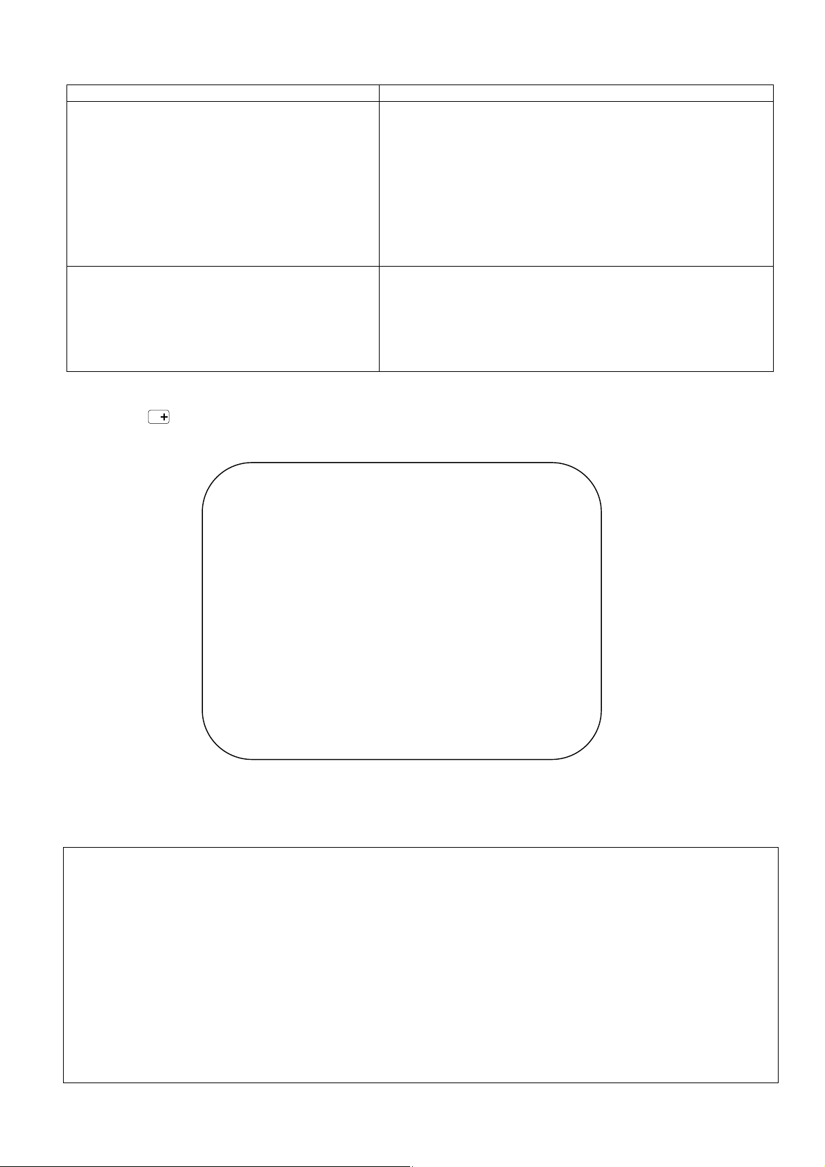
ADJUSTMENT PROCEDURE
Item / Preparation Adjustments
+B SET-UP
1. Receive a Window pattern.
2. Set the controls :
Brightness Minimum
Contrast Minimum
Volume Minimum
CUT OFF / Ug2 Test
1. Receive a Greyscale signal.
2. Degauss the tube externally.
3. Set the TV into Service Mode 1.
4. Select Cut off mode.
Confirm the following voltages.
TPD1 220 ± 10V TPD11 3,3 ± 0,2V
TPD2 137 ± 1,5V TPD12 5 ± 0,25V
TPD3 26,5 ± 1,5V TPD13 31 ± 1,5V
TPD4 5 ± 0,25V TPD14 26 ± 1V
TPD5 38 ± 1,5V TPD15 -13,5 ± 1V
TPD6 6,4 -0,5/+0,8V TPD16 13,5 ± 1V
TPD7 13,6 ± 0,5V TPG1 2,5 ± 0,2V
TPD9 8 ± 0,5V TPG2 3,3 ± 0,2V
TPD10 12 ± 0,5V
To adjust Cutoff connect an oscilloscope to the Blue cathode. Adjust
“cutoff” value using the “Yellow” and “Blue” buttons until the black
level is 160V +5V/-0V press “TV/AV” to store the value.
Remove the oscilloscope.
Select Ug2 adjustment and adjust the screen VR until the display
shows “O.K.”
SELF CHECK
Self-check is used to automatically check the bus lines and hexadecimal code of the TV set.To enter Self-Check mode, press
the STATUS button on the remote control and at the same time press the down (-/v) button on the customer controls at
the front the TV set. To exit Self Check, switch off the TV set at the power button.
VDP O.K.
TUN O.K.
E2 O.K.
PCB O.K.
CAB O.K.
SUM ****
MSP O.K.
Avs O.K.
DPL - - MAS - - -
OPTION 1 00
OPTION 2 E1
OPTION 3 82
OPTION 4 60
OPTION 5 B1
OPTION 6 E9
If the CCU ports have been checked and found to be incorrect or not located then " - - " will appear in place of "O.K.".
Service Aids
To aid in the service of our current chassis there are a number of Service Aids which have been made available.
· LUCI interface kit (Linked Utility Computer Interface)
Part number: TZS6EZ002
This contains interface and cables for connecting TV service connector and a PC as well as diagnostic software. As new
models are introduced upgrade software will become available.
· VICI (Visual Interactive Computer Information)
These C.D.'s contain multimedia documentation providing quick access to service information.
Part No. TZS7EZ006, TZS7EZ005, TZS8EZ001 & TZS9EZ001
1. Service Manuals
2. Instruction Books
3. Technical Information
· TASMIN (Technically Advanced System for Multimedia Interactive Notes)
As well as providing a first step towards more interactive training this product also achieves quick access to Technical
Information.
5
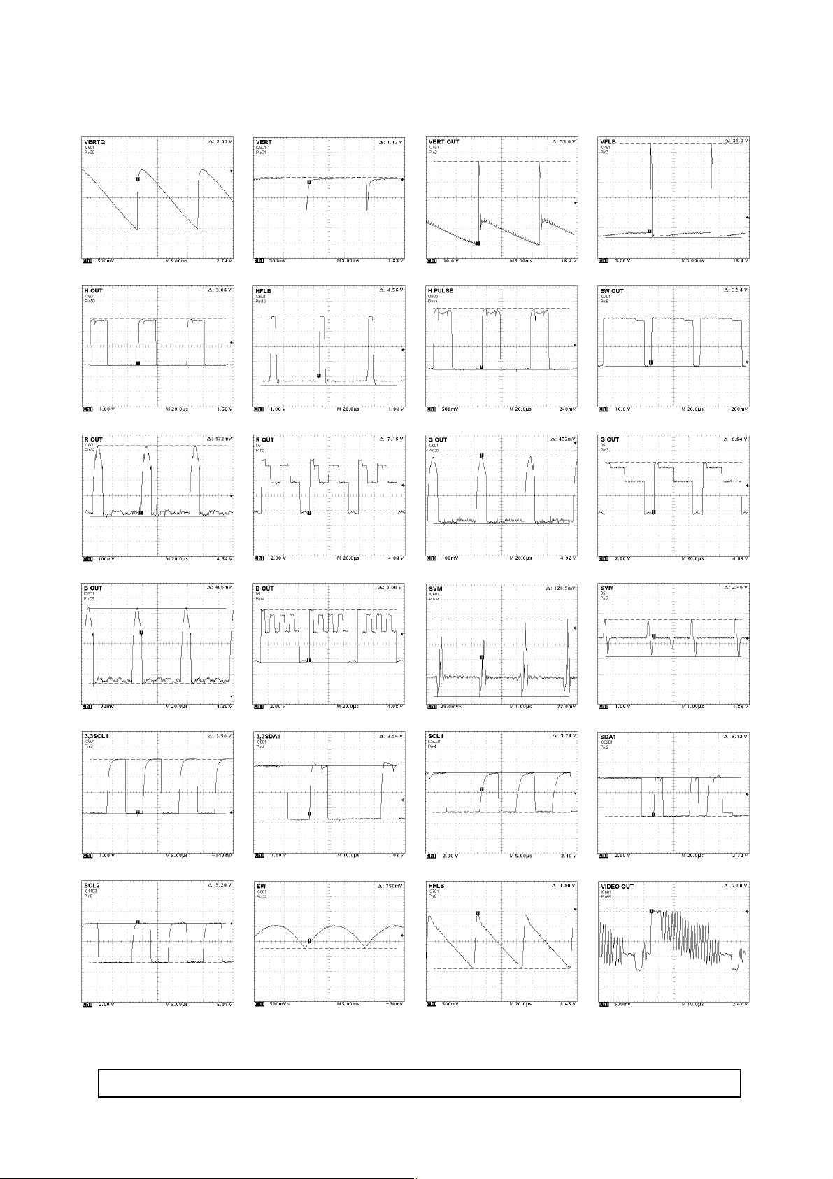
WAVEFORM PATTERN TABLE
CONDITIONS: CONTRAST...MAX, BRIGHTNESS...MID, COLOUR...MID, SHARPNESS...MID
6
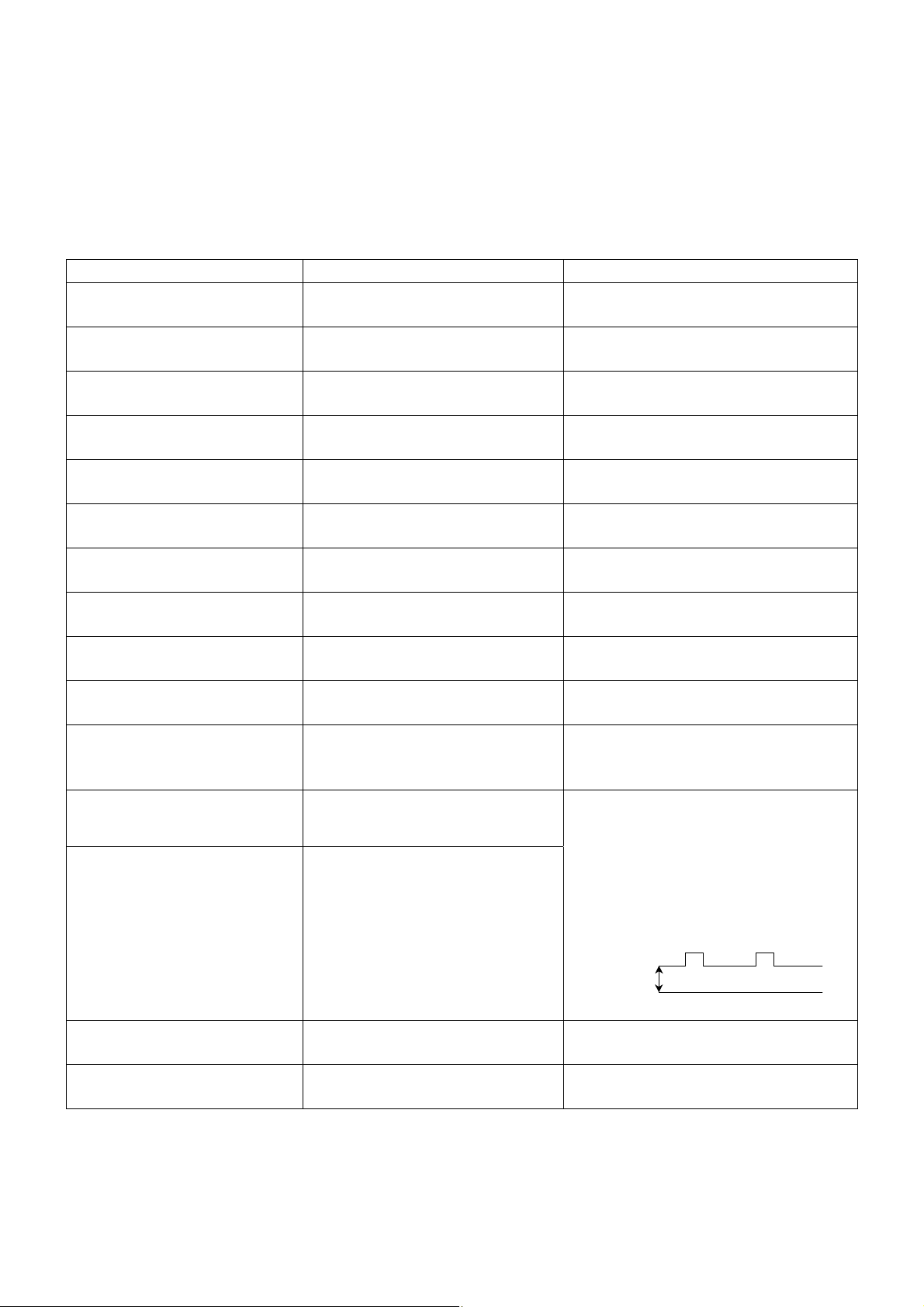
ALIGNMENT SETTINGS
(The figures below are nominal and used for representative purposes only.)
1. Set the Bass to maximum position, set the Treble to minimum position, set the Volume to minimum then press the
down button (-/v) on the customer controls at the front of the TV and at the same time press the INDEX button on the
remote control, this will place the TV into the Service Mode 1.
2. Press the RED / GREEN buttons to step up / down through the functions.
3. Press the YELLOW / BLUE buttons to alter the function values.
4. Press the TV/AV button after each adjustment has been made to store the required values.
5. To exit the Service Mode, press the "N" button.
Alignment Function Settings / Special features
Horizontal Position
Vertical Position
Horizontal Amplitude
Vert. Amplitude
EW-amplitude
EW-amplitude
Trapezium-comp
Trapezium-comp
Vertical Linearity
Vertical Symmetry
DVCO
Cut-off DC
Ug2 Test
H-Pos
025
V-Pos
008
H-Amp
004
V-Amp
060
EW-Amp 1
- 029
EW-Amp 2
005
Trapez 1
- 002
Trapez 2
003
V-Lin
- 018
V-Sym
- 004
DVCO
021
Cut-off
0204
Ug2
130
O.K.
Optimum setting.
Optimum setting.
Optimum setting.
Optimum setting.
Optimum setting.
Optimum setting.
Optimum setting.
Optimum setting.
Optimum setting.
Optimum setting.
Receive a PAL Colour Bar Pattern. For
DVCO alignment press "Blue" button, wait
until the colours are changing slowly and
press "TV/AV".
To adjust Cutoff connect an oscilloscope to
the Blue cathode. Adjust “cutoff” value
using the “Yellow” and “Blue” buttons until
the black level is 160V +5V/-0V, press
“TV/AV” to store the value.
Remove the oscilloscope.
Select Ug2 adjustment and adjust the
screen VR until the display shows “O.K.”
Black Level
160V+5V/-0V
GND
Highlight
Lowlight
Sub-Brightness
High 0902 0777 0864
Low 0117 0132 0112
Sub-Brightness
003
7
Optimum setting.
Optimum setting.
 Loading...