

Page 1

ORDER No. 03-SM-012
Service Manual
Colour Television
TX-32PX10D, TX-32PX10F,
TX-32PX10P
TX-28PX10D, TX-28PX10F
EURO- 9L Chassis
SPECIFICATIONS
(Information in brackets [ ] refers to models 28”)
Power Source: 220-240V a.c., 50Hz
Power Consumption: 114W [105W]
Stand-by Power
Consumption: 0,6W
Aerial Impedance: 75Ω unbalanced, Coaxial Type
Receiving System: PAL-I, B/G, D/K, PAL-525/60
SECAM B/G, D/K, L/L’
M.NTSC (AV only)
NTSC (AV only)
Receiving Channels:
VHF E2-E12 VHF H1-H2 (ITALY)
VHF A-H (ITALY) VHF R1-R2
VHF R3-R5 VHF R6-R12
UHF E21-E69 CATV (S01-S05)
CATV S1-S10 (M1-M10) CATV S11-S20 (U1-U10)
CATV S21-S41 (HYPERBAND)
Intermediate Frequency:
Video/Audio
Video 38,9MHz, 33,9MHz
Sound 33,4MHz (B/G), 33,16MHz (A2)
33,05MHz (NICAM B/G,D/K,L)
32,4MHz (D/K),32,66MHz (CZ STEREO)
40,4MHz (L’), 39,75MHz (L’NICAM)
Colour 34,47MHz (PAL)
34,5MHz, 34,65MHz (SECAM)
38,3MHz, 38,15MHz (SECAM L’)
Terminals:
AUDIO MONITOR OUT Audio (RCAx2) 500mV rms 1kΩ
AV1 IN Video (21 pin) 1V p-p 75Ω
Audio (21 pin) 500mV rms 10kΩ
RGB (21 pin) 0,7V p-p 75Ω
AV1 OUT Video (21 pin) 1V p-p 75Ω
Audio (21 pin) 500mV rms 1kΩ
AV2 IN Video (21 pin) 1V p-p 75Ω
Audio (21 pin) 500mV rms 10kΩ
S-Video IN Y: 1V p-p 75Ω
(21-pin) C:0,3V p-p 75Ω
AV2 OUT Video (21 pin) 1V p-p 75Ω
Audio (21 pin) 500mV rms 1kΩ
AV3 IN S-Video IN Y: 1V p-p 75Ω
(4-pin) C:0,3V p-p 75Ω
Audio (RCAx2) 500mV rms 10kΩ
Video (RCAx1) 1V p-p 75Ω
AV4 IN Video (21 pin) 1V p-p 75Ω
Audio (21 pin) 500mV rms 10kΩ
RGB (21 pin) 0,7V p-p 75Ω
S-Video IN Y: 1V p-p 75Ω
(21-pin) C:0,3V p-p 75Ω
AV4 OUT Video (21 pin) 1V p-p 75Ω
Audio (21 pin) 500mV rms 1kΩ
High Voltage: 32kV ± 1kV [30,5kV ± 1kV]
Picture Tube: W76ELE50X71 76cm
[W66EKT50X71 66cm]
Audio Output: 2x10W RMS, 2x20W MPO,
8Ω impedance
Headphones: 8Ω Impedance
Accessories
supplied : Remote Control
2 x R6 (UM3) Batteries
Dimensions:
Height: 567mm [510mm]
Width: 902mm [776mm]
Depth: 550mm [530mm]
Net weight: 56,5kg [42,5kg]
Specifications are subject to change without notice.
Weights and dimensions shown are approximate.
Page 2
CONTENTS
SAFETY PRECAUTIONS ......................................................................................................................................................... 2
SERVICE HINTS ...................................................................................................................................................................... 3
ADJUSTMENT PROCEDURE AND SELF-CHECK.................................................................................................................. 4
WAVEFORM PATTERN TABLE............................................................................................................................................... 5
ALIGNMENT SETTINGS .......................................................................................................................................................... 6
BLOCK DIAGRAMS.................................................................................................................................................................. 7
PARTS LOCATION................................................................................................................................................................. 12
REPLACEMENT PARTS LIST................................................................................................................................................ 13
SCHEMATIC DIAGRAMS....................................................................................................................................................... 29
CONDUCTOR VIEWS ............................................................................................................................................................ 34
SAFETY PRECAUTION
GENERAL GUIDE LINES
1. It is advisable to insert an isolation transformer in the
a.c. supply before servicing a hot chassis.
2. When servicing, observe the original lead dress in the
high voltage circuits. If a short circuit is found, replace
all parts that have been overheated or damaged by
the short circuit.
3. After servicing, see that all the protective devices
such as insulation barriers, insulation papers, shields
and isolation R-C combinations are correctly
installed.
4. When the receiver is not being used for a long period
of time, unplug the power cord from the a.c. outlet.
5. Potentials as high as 33kV [31,5kV] are present when
this receiver is in operation. Operation of the receiver
without the rear cover involves the danger of a shock
hazard from the receiver power supply. Servicing
should not be attempted by anyone who is not
familiar with the precautions necessary when working
on high voltage equipment. Always discharge the
anode of the tube.
6. After servicing make the following leakage current
checks to prevent the customer from being exposed
to shock hazard.
LEAKAGE CURRENT COLD CHECK
1. Unplug the a.c. cord and connect a jumper between
the two prongs of the plug.
2. Turn on the receiver’s power switch.
3. Measure the resistance value with an ohmmeter,
between the jumpered a.c. plug and each exposed
metallic cabinet part on the receiver, such as screw
heads, aerials, connectors, control shafts etc. When
the exposed metallic part has a return path to the
chassis, the reading should be between 4M ohm and
20M ohm. When the exposed metal does not have a
return path to the chassis, the reading must be
infinite.
LEAKAGE CURRENT HOT CHECK
1. Plug the a.c. cord directly into the a.c. outlet. Do not
use an isolation transformer for this check.
2. Connect a 2kΩ 10W resistor in series with an
exposed metallic part on the receiver and an earth,
such as a water pipe.
3. Use an a.c. voltmeter with high impedance to
measure the potential across the resistor.
4. Check each exposed metallic part and check the
voltage at each point.
5. Reverse the a.c. plug at the outlet and repeat each of
the previous measurements.
6. The potential at any point should not exceed
1,4 Vrms. In case a measurement is outside the limits
specified, there is a possibility of a shock hazard, and
the receiver should be repaired and rechecked before
it is returned to the customer.
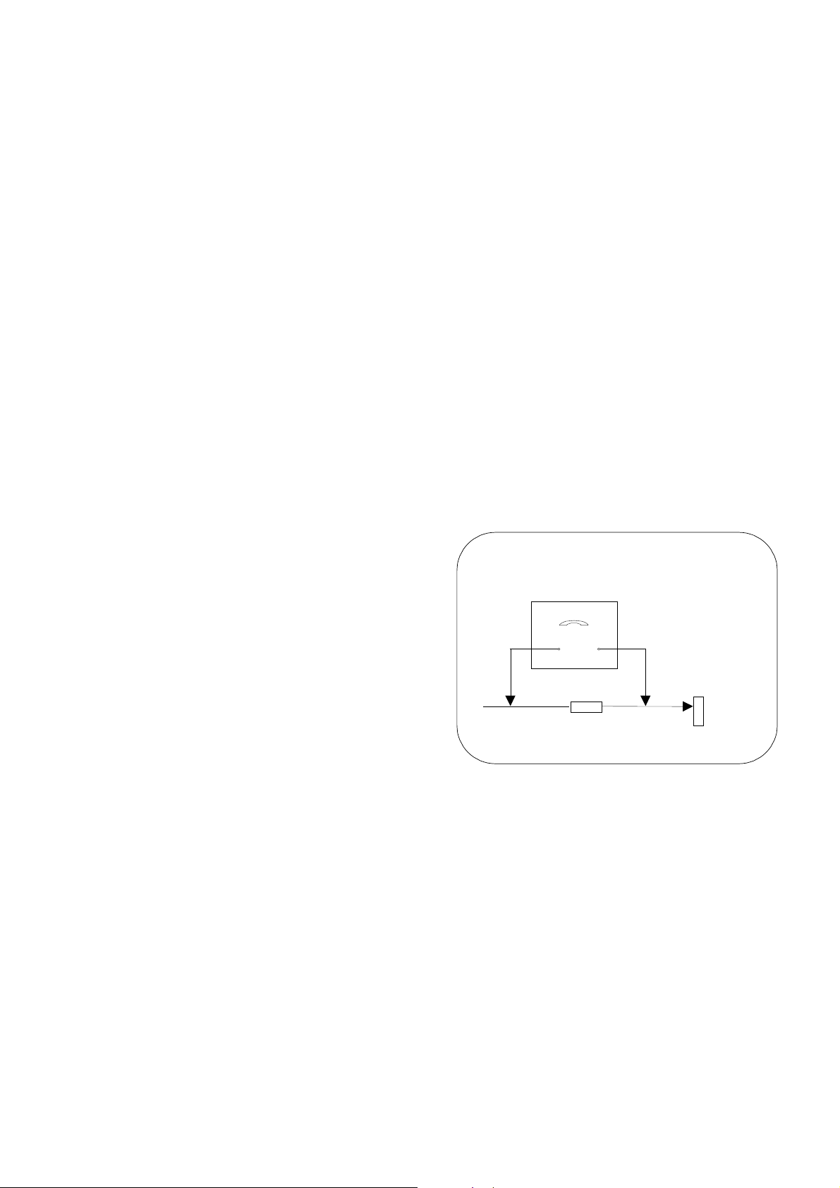
HOT CHECK CIRCUIT
a.c. VOLTMETER
2kΩ 10 Watts
TO INSTRUMENT'S EXPOSED
METALLIC PARTS
Fig. 1.
X-RADIATION WARNING
1. The potential sources of X-Radiation in TV sets are
the high voltage section and the picture tube.
2. When using a picture tube test jig for service, ensure
that the jig is capable of handling 33kV [31,5kV]
without causing X-Radiation.
NOTE: It is important to use an accurate periodically
calibrated high voltage meter.
1. Set the brightness to minimum.
2. Measure the high voltage. The meter should indicate:
32kV ± 1kV [30,5kV ± 1kV].
If the meter indication is out of tolerance, immediate
service and correction is required to prevent the
possibility of premature component failure.
3. To prevent any X-Radiation possibility, it is essential
to use the specified tube.
WATER PIPE
(
EARTH)
2
Page 3
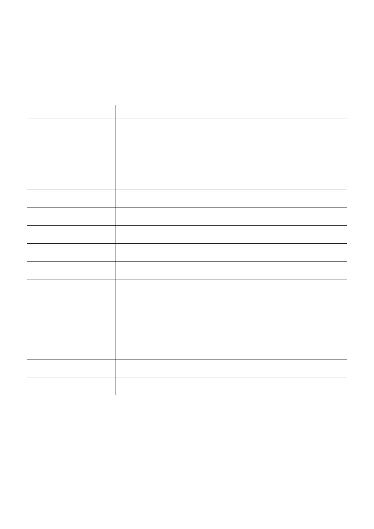
ALIGNMENT SETTINGS
(The figures below are nominal and used for representative purposes only.)
1. Set the Bass to maximum position, set the Treble to minimum position, set the Volume to minimum then press the
down button (-/v) on the customer controls at the front of the TV and at the same time press the INDEX button on the
remote control, this will place the TV into the Service Mode 1.
2. Press the RED / GREEN buttons to step up / down through the functions.
3. Press the YELLOW / BLUE buttons to alter the function values.
4. Press the STR button after each adjustment has been made to store the required values.
5. To exit the Service Mode, press the "N" button.
Alignment Function
Horizontal Position
Vertical Position
Horizontal Amplitude
Vert. Amplitude
EW-amplitude
Lower Corner
Trapezium-comp
Upper Corner
Vertical Symmetry
Vertical Linearity
Setting indication
Note: All setting values are approximate
H-Pos
21
V-Pos
27
H-Amp
41
V-Amp
-66
EW-Amp 1
- 25
Lower Corner
2
Trapez 1
-7
Upper Corner
-2
V-Sym
-4
V-Lin
40
Settings / Special features
Optimum setting.
Optimum setting.
Optimum setting.
Optimum setting.
Optimum setting.
Optimum setting.
Optimum setting.
Optimum setting.
Optimum setting.
Optimum setting.
Angle
Bow
DVCO
Highlight
Lowlight
Sub-Brightness
Angle
-2
Bow
0
DVCO
-1
High 0403 0318 0350
Low 0071 0132 0160
Sub-Brightness
20
Optimum setting.
Optimum setting.
Receive a PAL Colour Bar Pattern. For
DVCO alignment press "Blue" button, wait
until the colours are changing slowly and
press "STR".
Optimum setting.
Optimum setting.
6
Page 4
A
A
Y5A
Q1705 Q1708
R OUT
42
Q1704 Q1707
G OUT
43
Q1703 Q1706
B OUT
44
6 4 3 5
6 4 3 5
L2
A2
SENSE
35
CRT
IC1701
IC1501
39
R EXT
7A48
7H48
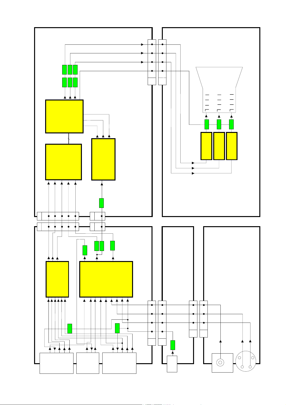
VIDEO BLOCK DIAGRAM
R EXT
12
DEFLECTION
PROCESSOR
DDP3315CQAE3
G EXT
G EXT11B EXT
0÷Y7
8bit
Y0÷Y7
IDEO SIGNAL
PROCESSOR
VSP9405VKB11
40
41
55
B EXT
MAIN Y/CVBS
9
11
9
11
10
52 53
51
B OSD
G OSD
R OSD
114
112
113
MICRO
IC1101
PROCESSOR
SDA6000-A23
56
MAIN C
12
12
Q3013
AV2 VIDEO OUT
41
A5
H5
MAIN Y/CVBS
Q3301
56
121
TEXT CVBS
Q1125
1
1
Q3016
MAIN C
A - BOARD
Q3011
58
H - BOARD
L - BOARD
D - BOARD
Q351
IC351
R OUT
3
G - BOARD
IC361
G OUT
3
71
IC371
B OUT
3
IC3001
CXA2069Q
12
1
AV4
Y/VIDEO IN 20
MATRIX
IDEO/AUDIO
3
63
V3 CVBS
V3
Q3014
VIDEO OUT 19
C/RED IN 15
TUNER CVBS
BLUE IN 7
GREEN IN 11
V3 C
15 20 21 22
H1
15 20 21 22
D1
VIDEO
TUNER
1 2 4
D8
1 2 4
G7
AV3
C
AV1
IC3301
2G13
R1
VIDEO IN 20
MATRIX
RGB & FB SW
TDA8601T/C1
7
6
8
4
R2
B2
B1
G2
Q3015
BLUE IN 7
RED IN 15
GREEN IN 11
VIDEO OUT 19
AV2
24, 22
AV1 VIDEO IN
Y/VIDEO IN 20
17, 15
AV2 Y/ VIDEO IN
VIDEO OUT 19
19
10, 8
AV2 C IN
AV4 C IN
AV4 Y/ VIDEO IN
C IN 15
7
Page 5
AM
TUNER
MSP
Q102
Q101
102
101
Q106
IC251
LA4282
R OUT 7
L OUT 11
AUDIO OUTPUT
2 L IN
5 R IN
4 1
D17
4 1
G16
G14
L
R
1
4
AV3
R
HEADPHONE
L
2 L
3 R
IC2001
NA IN 1
67
60 MONO IN
UDIO
PROCESSOR
78 D CTRL
MSP3410GAB83
36
57
AV3 R
25D124
25H124
37
AV3 L
TUNER L
TUNER R
18
17
18
17
R OUT
9
9
56
L OUT
8 8
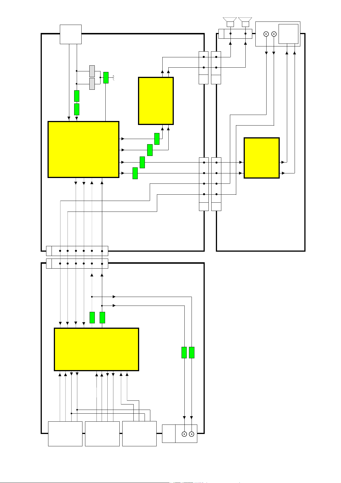
AUDIO BLOCK DIAGRAM
28
27
24 25
SPKR OUT L
SPKR OUT R
HP L
HP R
Q2005
Q2002
Q2003
Q2004
6 7 16 14
6 7 16 14
D8
G7
D - BOARD
G - BOARD
IC2351
NJM4556AD
OP. AMPLIFIER
3 HP L
5 HP R
HP L 1
HP R 7
H - BOARD
AV1
AV3 R2AV3 L
4
25
AV1 R IN
RIGHT IN 2
23
AV1 L IN
LEFT IN 6
TUNER R
64
IC3001
CXA2069Q
45
43
AV1 L OUT
AV1 R OUT
LEFT OUT 3
RIGHT OUT 1
TUNER L
MAIN R
62
MATRIX
IDEO/AUDIO
Q3010
Q3009
MAIN L
54
52
Q3006
Q3005
18
16
AV2 L IN
AV2 R IN
LEFT IN 6
AV2
RIGHT IN 2
11
40
AV2 R OUT
RIGHT OUT 1
9
38
AV4 L IN
AV4 R IN
AV2 L OUT
AV4
LEFT IN 6
LEFT OUT 3
RIGHT IN 2
LEFT OUT 3
RIGHT OUT 1
OUT
AUDIO
L
MONITOR
R
8
Page 6
Y
A
RC SIG
SDA3
SDA1
SCL1
SDA2
SCL2
SCL3
7
8
56
234
D3
SCL2
SDA2
TUNER
SCL2
SDA2
SCL3
SDA3
353332
34
D2
SDA2
Q103
AFC
SDA2
SCL2
SCL2
IC2001
3 SDA2
2 SCL2
SDA1
SCL1
31
AFC
UDIO
PROC.
21 RESET
BUS
ON/OFF
282715
30
AV1
8 SLOW1
10 (SCL3)
D1001
IC1900
H1
Q3001
SERVICE
H - BOARD
BUS
D - BOARD
G - BOARD
Q1901
LED SBY
ROTATION
Q251
Q252
Q2001
FBT, HEATER
G7
D8
Q1002
9
9
RC1001
RC SIG
101112
101112
RC RECEIVER
KEYSCAN
Q2006
SMUTE2
UDIO MUTE
RST MAIN
KEYSCAN
RC SIG
LED SB
ROTATION
D28 G18
POWER SUPPLY
ON/OFF
6
6
30
28
6
4
123
462830
123
D1
AFC
PROT1
AV2
16 FBIN1
12 (SDA3)
8 SLOW2
Q3000
SCL3
SDA3
568
H5
AV4
8 SLOW4
10 AV LINK
16 FBIN2
14
15
MATRIX
IC3301
13
RGB & FB SW
5
CH SEL
SDA3
SCL3
SLOW1
SLOW2
SLOW4
Q3017
Q3003
Q3004
AUDIO MUTE
SERVICE
KEYSCAN
9
RC SIG
LED SBY
141516
ROTATION
17
36
34
33
27
MATRIX
IC3001
20
IDEO/AUDIO
13
Q3007
Q3008
Q3018
RST MAIN
AV LINK
H4
6
3
18
24
RESET
FBL1
IDEO SIGNAL
31
30
37
PROCESSOR
282715
Q1104
ROTATION
PWM1 20
VPROT 32
SDA1 (3,3V)
SCL1 (3,3V)
SDA1 (3,3V) 64
ON/OFF
RST MAIN
RESQ 62
SCL1 (3,3V) 63
IC1701
DEFLECTION
BUS
Q1718
Q1717
VSTBY 24
PROCESSOR
PROT1
SCL1 (3,3V)
SDA1 (3,3V)
SDA1
ON/OFF
SCL1 (3,3V)
SDA1 (3,3V)
IC1107
BUS LEVEL
MICRO
IC1101
35A1343332
BUS
RST MAIN
SCL1 (3,3V)
SDA1 (3,3V)
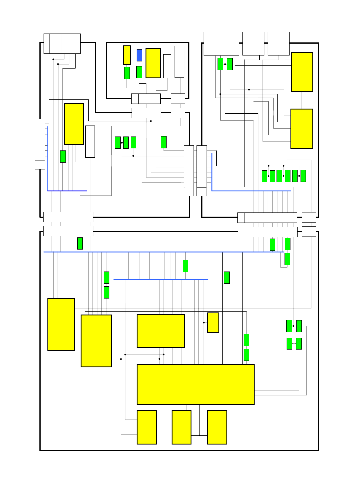
CONTROL BLOCK DIAGRAM
SDA1 (3,3V) 6
SCL1 (3,3V) 13
IC1501
SCL1
SDA2
SCL1
SDA1
SDA1 18
SHIFTER
3,3V=>5V
2 SDA1
SDA1 99
PROCESSOR
568
9
A5
141516
Q1113
AFC
RC SIG
SERVICE
LED SBY
SCL2
SCL3
SDA3
Q1106
LED SBY
RST MAIN
AUDIO MUTE
KEYSCAN
3
17
18
Q1116
Q1115
6
A4
FBL1
AV LINK
Q1112
SCL2
SDA2
SDA3
SCL3
PROT1
ON/OFF
RESET IN
AUDIO MUTE
4
SCL1 17
SCL2 15
SCL3 13
SDA2 16
SDA3 14
3 SCL1
4 SDA2
7 SCL3
5 SCL2
6 SDA3
93
92
SDA2 101
SCL2 100
SCL3 74
SDA3 75
PROT1
ON/OFF
SCL1 98
46 CSROM
73
RST IN
AUDIO MUTE 90
D0÷D15
IC1103
44 CSSDRAM
76
125
AFC
SERVICE
AV LINK OUT 7
Q1102Q1101
5
77
124
RC SIG
VPROT 12
LED SBY
KEYSCAN
AV LINK IN 6
Q1111
Q1108
Q1110
Q1109
6
SCL1
EAROM
5
IC1104
SDA1
A - BOARD
CE 26
IC1102
FLASH MEMORY
D0÷D15
19
CS
D0÷D15
SDRAM
IC1106
9
Page 7
VERT DY
V
3
D16
HORIZ DY
1
4
D15
DIODE
MODULATOR
10
FBT
DAF
Used only
for 32” models
8
8
-DAF
H-DAF
127
127
D14
DF1
Q523
3
8
IC451
VERTICAL
6
LA7876N
D - BOARD
A - BOARD
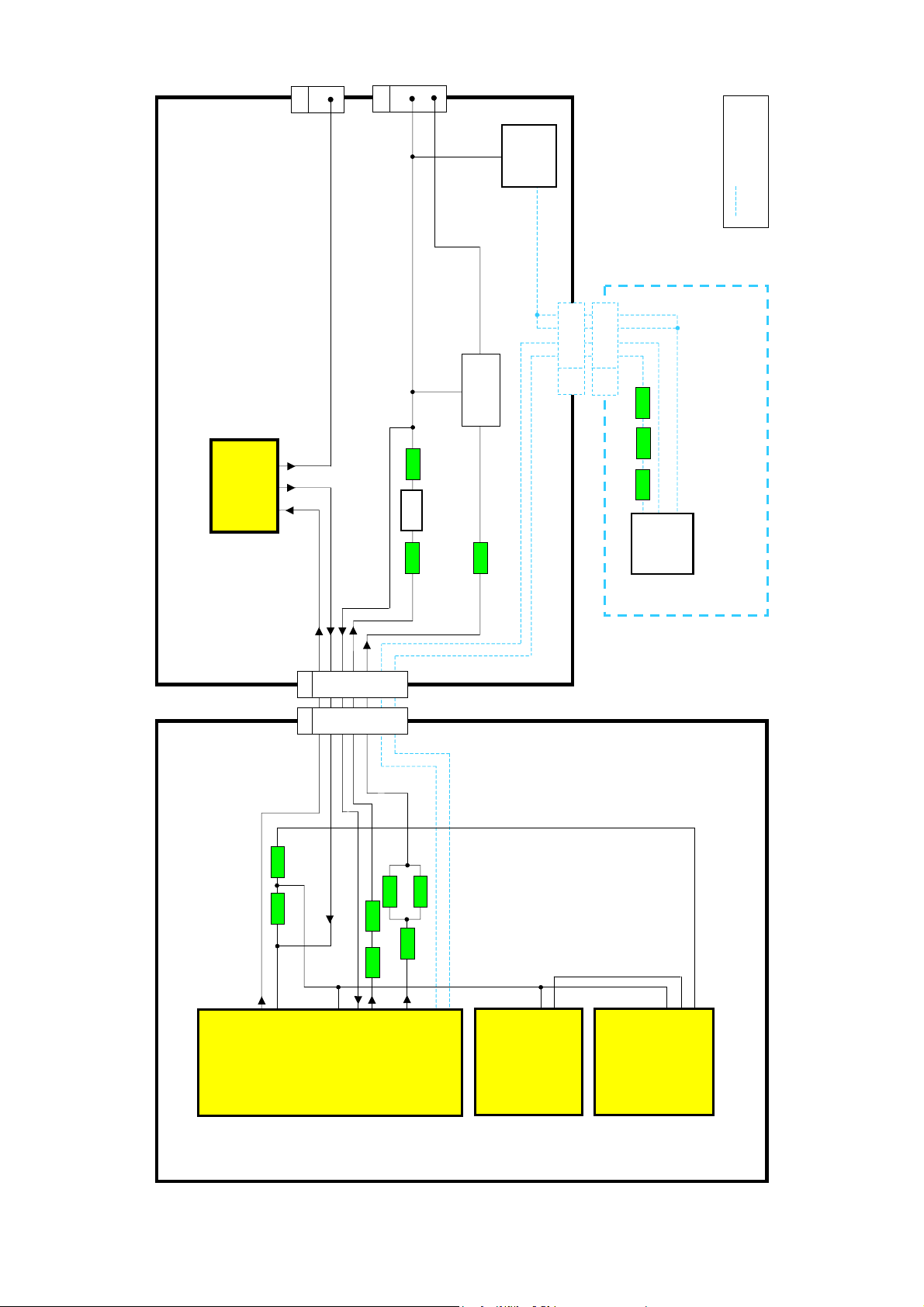
DEFLECTION BLOCK DIAGRAM
Q1102 Q1101
Q522
Q551
Q521
T501
Q503
Q703
581
T701
DF - BOARD
HFLB
H DRIVE
VFLB
EW
12
964
964
VDAF
HDAF
2
1
2
1
EW
H DRIVE
Q1713
Q1714
Q1715
Q1701 Q1702
VERT+
13
D2
13A112
V SYNC
VFLB
VS 23
H SYNC 8
IDEO SIGNAL
PROCESSOR
VSP9405VKB11
MICRO
IC1101
SDA6000-A23
V SYNC 102
PROCESSOR
H SYNC 103
V PROT 12
IC1701
DDP3315CQAE3
DEFLECTION
PROCESSOR
VS 10
VERT+ 37
VPROT 32
HFLB 30
EW 39
VDAF 22
HOUT 23
HDAF 25
IC1501
10
Page 8
r
r
r
UDIO
V
V
V
V
V
V
V
V
V9V
V8V
V8V
V
V15V
V
IC251
OUTPUT
10
41V/AUDIO2
T849
42V
Q898
D884
D897
10
9VIN
Q897
D896
28V/AUDIO1
11
9V HEADER
10,5V
5DRAIN
3
4
5V HEADER
D870
6,5V
13
2
IC849
D871
14
1
POWER
5V HEADER
IC3807
R887
D895
137V
18
2VCC
5
SUPPLY
2
5V
1GND
4
R843
+5V
TUNER
D847
R842
+33V
IC899
POWER BUS
9V
9V HEADER
4
+5V
2
IC3801
21
IC3804
1
8V
5V HEADER
1
IC38023IC3803
39
65,66
UDIO
PROC.
IC2001
11,12,13
5V STBY
SB2,5V
2
IC3806
3
3
VERT
IC451
7
2
15V
-15V
D557
D558
2
7
1
9
T551
D554
R567
8V
3
1
8
5
5
SB3,3V
1
4
IC3805
2
T501
27V
D553
8
SB2,5
SB5
SB3,3
147
5V
26
24 25
22
10 17 20
D2
26
24 25
22
10 17 20
A1
3,3V_STBY
5
5
3,3
A- BOARD
15
82
1,8V
3
1
IC1502
IC1103
5
9V
Q1706
1,8V
IC1501
IC1105
2
5V
9V
Q1707
1,8V
5,28,34,66
VIDEO
3,3V_STBY
9V
Q1708
3,3V
3,3V
7,12,25,72
35,42,50,64,68
IC1108
5
9V
Q1719
44,59
IC1106
1,3,9,14
3,3V_STBY
3,3V_STBY
POWER BUS
3,3V
3,15
SDRAM
27,43,49
5V
3,3V
73
47
IC1701
DEFLECTION
IC1102
37,47
3,3V_STBY
3,3V_STBY
3,3V_STBY
3,3V_STBY
2,5V_STBY
2,5V_STBY
21,87
85,106
14,32,42
53,61,69
111,116,119,123
MICRO
IC1101
FLASH MEM
5V_STBY
IC1107
BUS L. SHIFT.
20
9V
A2
EAROM
IC1104
8
3,3V_STBY
1
D13
9
27 34
9
27 34
D- BOARD
1
D11
1G43
0V
400V
+
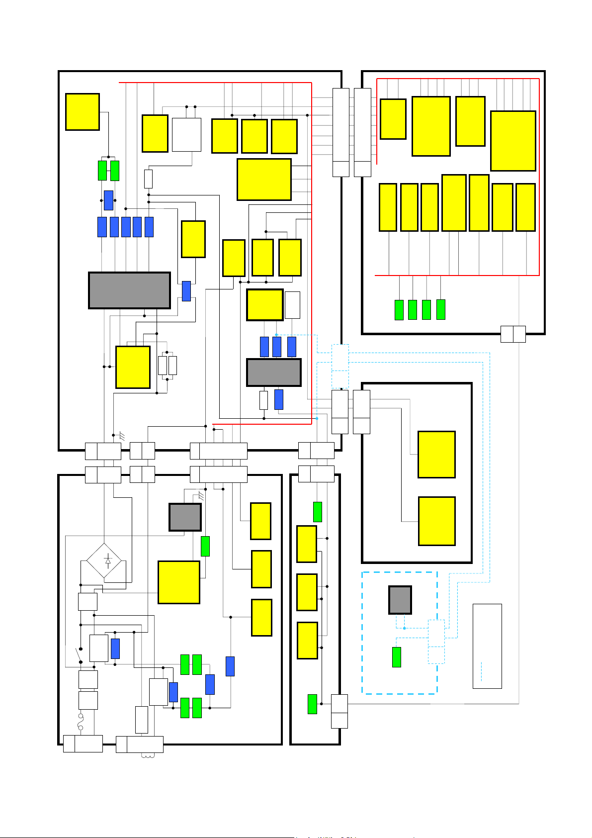
POWER SUPPLY BLOCK DIAGRAM
~
PFC
D801
-
Filte
5V SBY
3
1
D28
1
G18
~
2,3,7,8
SB5V
S1
T860
P2
SUPPLY
IC801
STBY POWER
SB5V HEADER
9V HEADER
9V
3
15
11
12
D9
3
15G612
11
S2
P1
Q860
5
4
POWER BUS
SB5V
1
1
VCC
RC1001
8
IC2351
10
IC1900
D854
RL801
S801
Q853
Line
Line
F801
1G14
MAINS IN
Q854
Filte
D860
Filte
RL803
Q856
Q855
D807
1G22
DEGAUSS
COIL
D861
D862
G - BOARD
L- BOARD
1
D12
1L33
147V
Q908
6
2
IC371
6
2
IC361
6
2
IC351
Q906
H1
D1
3
200V
42
1
MATRIX
IC3001
IDEO/AUDIO
MATRIX
IC3301
RGB & FB SW
H- BOARD
T701
147
28
Used only
Q522
DF- BOARD
9V
1
L2
DF2
for 32” models
11
Page 9
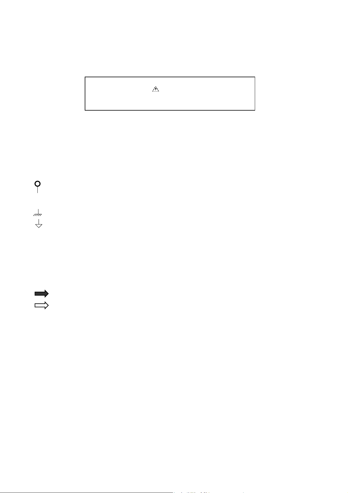
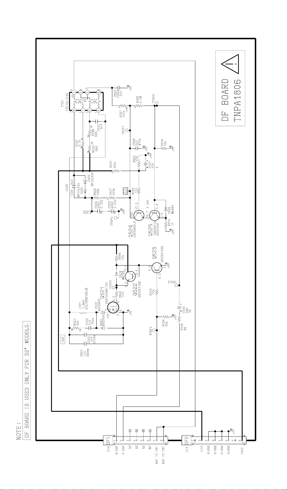
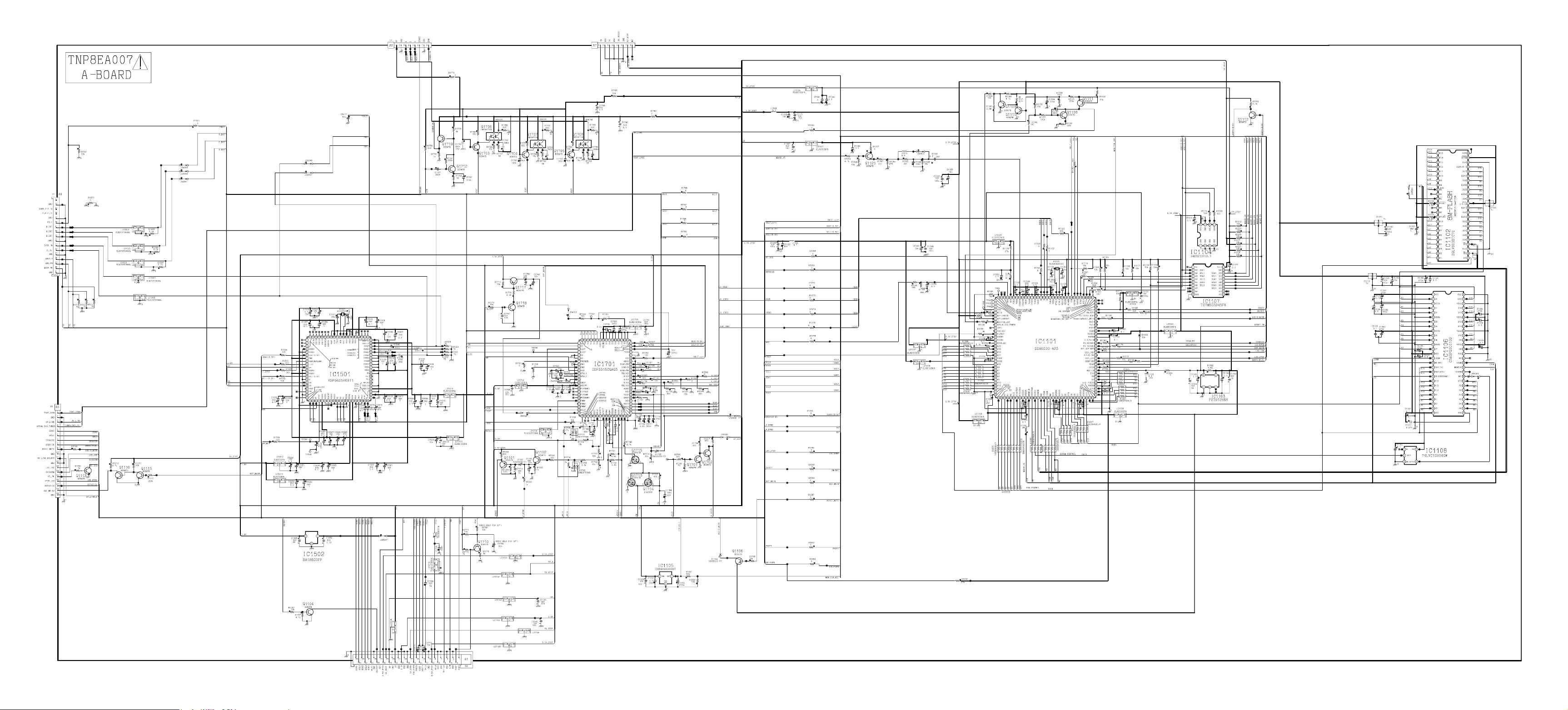
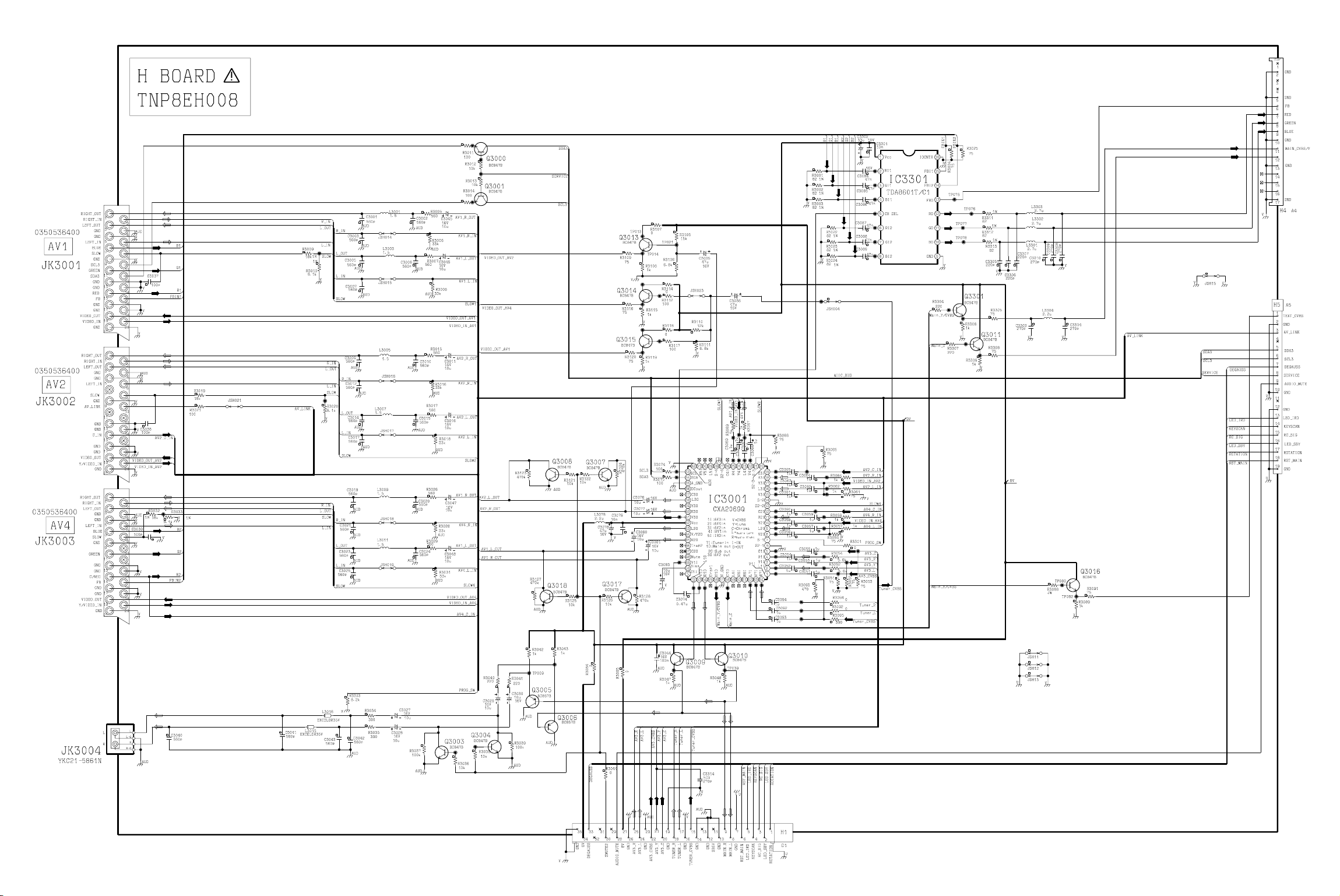
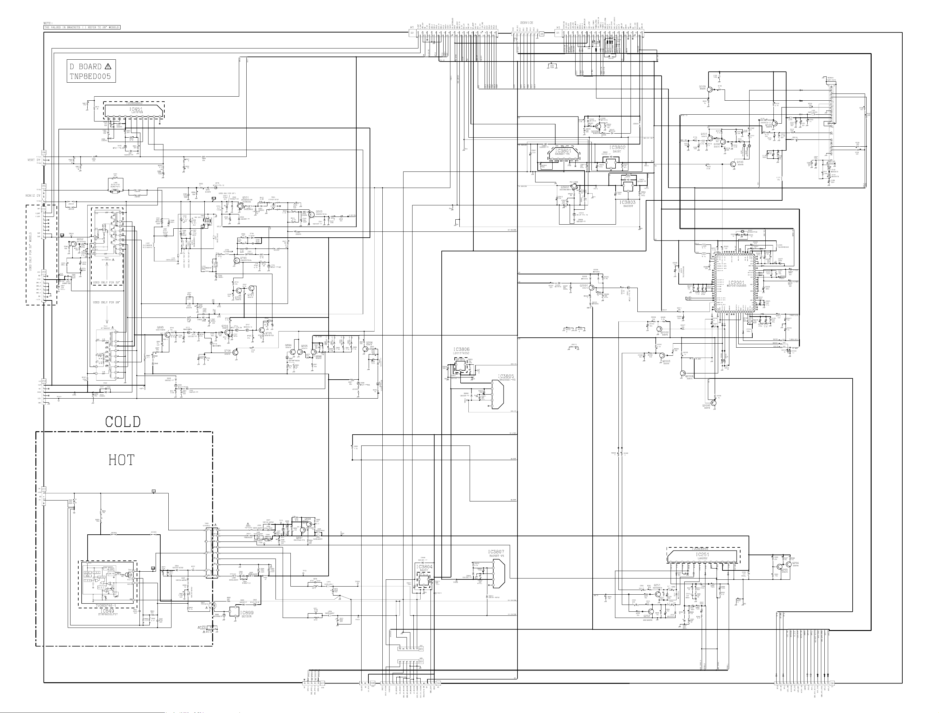
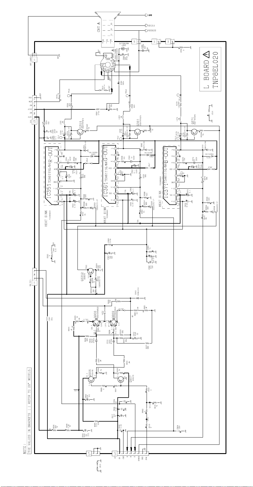
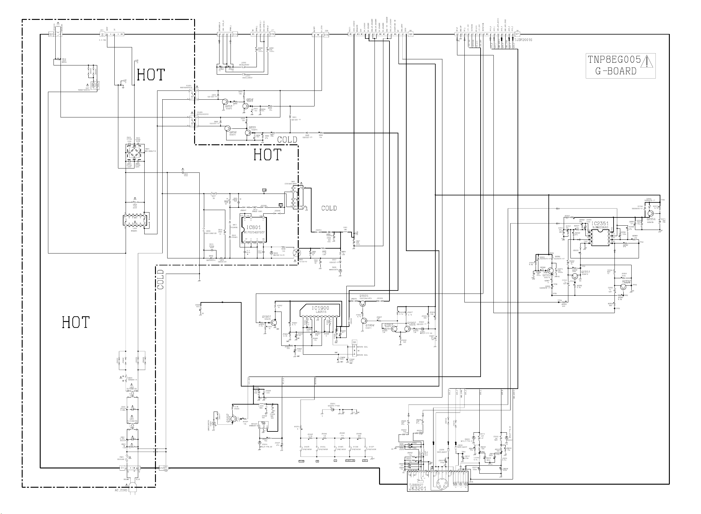
SCHEMATIC DIAGRAMS FOR MODELS
TX-32PX10D, TX-32PX10F, TX-32PX10P
TX-28PX10D, TX-28PX10F
(EURO-9L CHASSIS)
IMPORTANT SAFETY NOTICE
Components identified by mark have special characteristics
important for safety. When replacing any of these components, use
only manufacturers' specified parts.
NOTE
1. RESISTOR
All resistors are carbon ¼W resistor, unless marked otherwise.
Unit of resistance is OHM (Ω) (k=1,000, M=1,000,000)
2. CAPACITORS
All capacitors are ceramic 50V unless marked otherwise.
Unit of capacitance is µF unless otherwise stated.
3. COIL
Unit of inductance is µH, unless otherwise stated.
4. TEST POINT
Test Point Position
5. EARTH SYMBOL
Chassis Earth (Cold)
Line Earth (Hot)
6. VOLTAGE MEASUREMENT
Voltage is measured by a d.c. voltmeter.
Measurement conditions are as follows:
Power source a.c. 220V-240V, 50Hz
Receiving Signal Colour Bar signal (RF)
All customer controls Maximum position
7.
Indicates the Video signal path
Indicates the Audio signal path
These schematic diagrams are the latest at time of printing and are subject to change without notice.
REMARKS
a. Do not touch the hot part, or the hot and cold parts at the same time, as you are liable to a shock hazard.
b. Do not short circuit the hot and cold circuits as electrical components may be damaged.
c. Do not connect an instrument, such as an oscilloscope, to the hot and cold circuits simultaneously as this may cause
fuse failure. Connect the earth of the instruments to the earth connection of the circuit being measured.
d. Make sure to disconnect the power plug before removing the chassis.
NOTE
1. The Power Supply Circuit contains a circuit area, which uses a separate power supply to isolate the earth connection.
The circuit is defined by HOT and COLD indications in the schematic diagram. All circuits, except the Power Circuit, are
COLD.
29
Page 10
Page 11
Page 12
Page 13
Page 14
Page 15
 Loading...