Panasonic Training 9th Gen Schematic

9th Generation Plasma Display
Technical Information
1

The technicians have express their needs and we listened.
This presentation has been developed especially for the technicians involved in the repair of our plasma televisions.
We’ve gathered and analyzed your emails, questions, feedback, and requests. Based on this information, we have put together a presentation to fulfill your needs.
2

Topics
•Power Supply/System Control Interaction
•Boards Isolation
•Understanding SOS Condition
•Video Processing
•Troubleshooting
3

9th Generation Plasma Display Television
•What really happens when the TV is plugged in?
4

Sequence of Events when the TV is Plugged In
When the Plasma TV is plugged in, there’re a few indications of normal operation. Knowing this will help us understand what’s going on with the unit when an abnormality occurs.
1.There is a click from the relays RL402 and RL403 when they are activated.
2.The LED in the Optical Jack inside the DT board turns on for approx. 4 seconds.
3.Immediately after that, one of the Tuner LEDs (Right) turns on (Solid Red) for approximately 20 seconds.
4.The LED in the Optical Jack inside the DT board turns on again for approx. 1 second and both LEDs (tuner and optical jack) turn off.
5.Then you will hear another click from the relays RL402 and RL403 indicating that they are no-longer engaged. (Note: At this time the Tuner and the Optical Jack LED turn off.)
5

Standby Block (Part 1)
6

Standby Block (Part 2)
7

Power Supply (Standby Circuit)
8

Power Supply (Standby Circuit)
SS34 Connector
9

STB5V Distribution
10

STB5V Test Point (P board)
11

STB5V Test Point (PA board)
12

Power Supply (Standby Circuit)
Tuner SUB ON = Command to turn the relays on.
13

F-STB-ON (Primary)
T404
H
H
H
L
L H
14

F-STB-14V and PFC Test Points
15

F-STB-14V
H
L
16

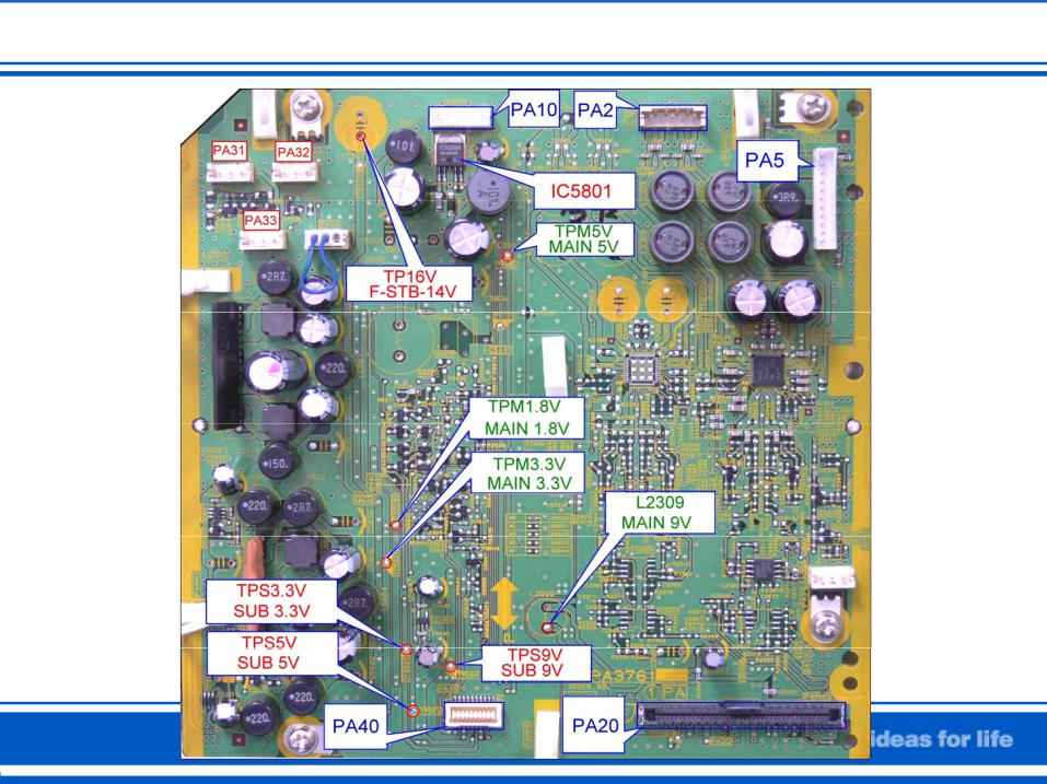
SUB-Voltages Output From the PA Board
17

PA Board Test Points
18

Power On/Off Operation
19

Power Off
20

Power On
21

Power Supply Secondary Circuit (1)
L H
22

Power Supply Secondary Circuit (2)
23

Power Supply Connectors
24

PA board Circuit Explanation
25

Main-Voltages Output From the PA Board
26

No Power Troubleshooting Chart
Can the click sound from the relays be heard after the TV is plugged into the wall outlet?
No |
Yes |
Is there 5V at pin 1 of connector PA40 on the PA board?
Yes
No
Replace the P Is there 2.5V at pin 13 of Board. connector P25 on the P
board?
Wait for approx. 20 seconds after applying AC to the TV. Then turn the power on.
Can the click sound from the relays be heard while attempting to turn the power on?
Yes 
 No
No  No Yes
Replace the P |
Replace the |
No |
Is there 3.3V at pin 1 of |
Replace the P |
|
Board. |
DG Board. |
connector HC01 on the HC |
Board. |
||
|
|
|
board? |
Yes |
|
|
|
|
|
Yes |
|
|
Replace the D |
No |
Is there 2.5V at pin 17 of |
||
|
Board. |
|
connector P25 on the P |
||
board?
27

Shutdown Detect Circuits
Understanding how the SHUTDOWN circuit works
SOS
28
 Loading...