

Page 1
WARRANTY - Australia only
1. The product is warranted for 12 months from the date of purchase. Subject to the conditions of this warranty Panasonic or it’s Authorised
Service Centre will perform necessary service on the product without charge for parts or labour if, in the opinion of Panasonic, the product is
found to be faulty within the warranty period.
2. This warranty only applies to Panasonic products purchased in Australia and sold by Panasonic Australia or its Authorised Distributors or Dealers
and only where the products are used and serviced within Australia or it’s territories. Warranty cover only applies to service carried out by a
Panasonic Authorised Service Centre and only if valid proof of purchase is presented when warranty service is requested.
3. This warranty only applies if the product has been installed and used in accordance with the manufacturer’s recommendations (as noted in the
operating instructions) under normal use and reasonable care (in the opinion of Panasonic). The warranty covers normal domestic use only
and does not cover damage, malfunction or failure resulting from use of incorrect voltages, incorrect installation, accident, misuse, neglect,
build-up of dirt or dust, abuse, maladjustment of customer controls, mains supply problems, thunderstorm activity, infestation by insects or
vermin, tampering or repair by unauthorised persons (including unauthorised alterations), exposure to abnormally corrosive conditions or any
foreign object or matter having entered the product.
4. This warranty does not cover the following items unless the fault or defect existed at the time of purchase:
(a) Video or Audio Tapes (d) Cabinet Parts (g) Microwave Oven cook plates.
(b) Video or Audio Heads and Stylii resulting (e) User replaceable Batteries (h) Kneader mounting shaft unit
from wear and tear in normal use (f) Thermal Paper, Toner/Ink Cartridges, (bread bakery)
(c) Shaver Heads or Cutters Drums, Developer, Film (Ink/Ribbon),
5. If warranty service is required you should:
• Telephone Panasonic’s Customer Care Centre on 132600 or visit our website and use the Service Centre Locator for the name/address of
the nearest Authorised Service Centre.
• Send or bring the product to a Panasonic Authorised Service Centre together with your proof of purchase receipt as a proof of purchase date.
Please note that freight and insurance to and / or from your nearest Authorised Service Centre must be arranged by you.
• Note that home or pick-up/delivery service is available for the following products in the major metropolitan areas of Australia or the normal
operating areas of the nearest Authorised Service Centres:
(a) Picture tube (CRT) based Television Receivers (screen (b) Convection/Combination Microwave Ovens
sizes greater than 66cm); Rear Projection TV’s; Plasma/LCD (c) Whiteboard (except portable type)
televisions / displays (screen size greater than 103 cm)
6. The warranties hereby conferred do not extend to, and exclude, any costs associated with the installation, de-installation or re-installation of a
product, including costs related to the mounting, de-mounting or remounting of any screen, (and any other ancillary activities), delivery,
handling, freighting, transportation or insurance of the product or any part thereof or replacement of and do not extend to, and exclude, any
damage or loss occurring by reason of, during, associated with, or related to such installation, de-installation, re-installation or transit.
Panasonic Authorised Service Centres are located in major metropolitan areas and most regional centres of Australia, however, coverage will vary
dependant on product. For advice on exact Authorised Service Centre locations for your product, please telephone our Customer Care Centre on
132600 or visit our website and use the Service Centre Locator.
Unless otherwise specified to the consumer the benefits conferred by this express warranty are additional to all other conditions, warranties,
guarantees, rights and remedies expressed or implied by the Trade Practices Act 1974 and similar consumer protection provisions contained in
legislation of the States and Territories and all other obligations and liabilities on the part of the manufacturer or supplier and nothing contained
herein shall restrict or modify such rights, remedies, obligations or liabilities. November 2005
Film Cartridge, Printer Heads
THIS WARRANTY CARD AND THE PURCHASE DOCKET (OR SIMILAR PROOF OF PURCHASE)
SHOULD BE RETAINED BY THE CUSTOMER AT ALL TIMES
If you require assistance regarding warranty conditions or any other enquiries,
please visit the Panasonic Australia website
www.panasonic.com.au or by phone on 132 600
If phoning in, please ensure you have your operating instructions available.
Panasonic Australia Pty. Limited
ACN 001 592 187 ABN 83 001 592 187
PRO-031-F01 Issue: 3.0 23-11-2005
Locked Bag 505, Frenchs Forest, NSW 2086
www.panasonic.com.au
Customer’s Record
The model number and serial number of this product may be found on its rear panel. You should note this serial
number in the space provided below and retain this book, plus your purchase receipt, as a permanent record of
your purchase to aid in identification in the event of theft or loss, and for Warranty Service purposes.
Model Number Serial Number
Web Site: http://panasonic.net/
© Panasonic Corporation 2009
Printed in Japan
PBS0709H0
Page 2
Operating Instructions
Plasma Television
Model No. TH-P54Z1A
Thank you for purchasing this Panasonic product.
Please read these instructions before operating your set and retain them for future reference.
The images shown in this manual are for illustrative purposes only.
English
TQBC2476
Page 3
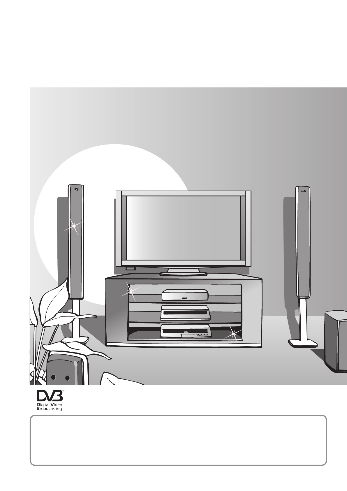
Turn your own living room into a movie theatre!
Experience an amazing level of multi-
Receive digital terrestrial services using an integrated Digital TV tuner
Sharp pictures with HDMI terminal
Create home theatre and DVD recorder link-ups with “VIERA Link”
without complicated settings!
2
Trade Mark of the DVB Digital Video Broadcasting Project (1991 to 1996)
TH-P54Z1A Declaration of Conformity No. 6420, 13 January 2009
Notice about Digital TV Functions
The MPEG-4 AVC feature was designed to specifications as we know them today. This
●
specification may be subject to future changes beyond our control that may not guarantee
the decoding of such services.
February 2009
Page 4
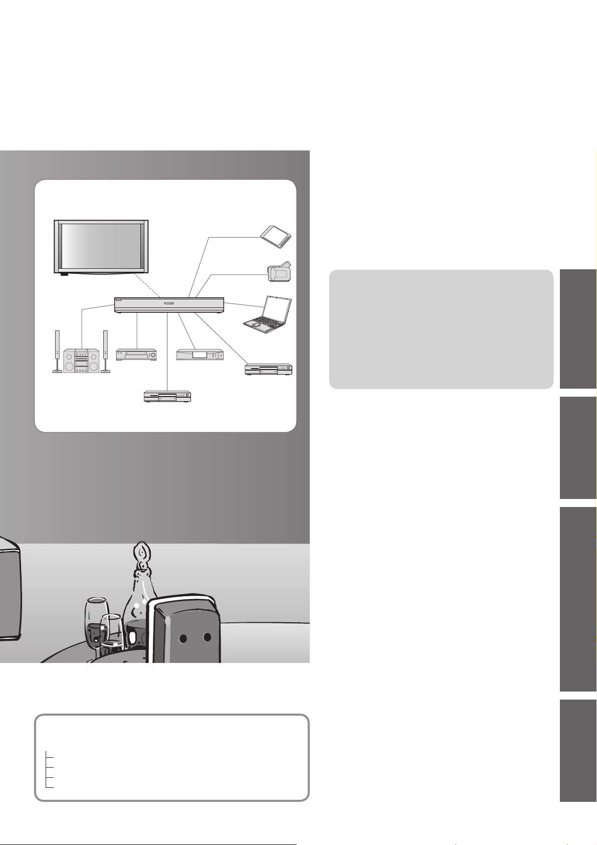
media excitement
Enjoy rich multimedia
SD memory card
Contents
Be Sure to Read
Safety Precautions ······································· 4
●
(Warning / Important Installation Notices)
●
Maintenance ················································· 6
Amplifier
Home theater
system
VCR
DVD Recorder
Set top box
Camcorder
Personal
computer
DVD player
Quick Start Guide
Options ·························································6
●
Accessories ··················································7
●
●
Basic Connection ·······································12
●
Identifying Controls ·····································16
●
Auto Tuning ················································18
●
Pairing Remote Control ······························19
Basic Features
Watching TV ··············································· 20
●
●
Using TV Guide ·········································· 23
●
Viewing Teletext ·········································· 24
●
Watching Videos and DVDs ······················· 26
Advanced Features
How to Use Menu Functions ······················ 28
●
(picture, sound quality, etc.)
●
Input Labels ················································ 32
●
Digital TV Settings ······································ 33
●
Editing Channels ······································· 34
●
Tuning Channels ········································ 36
●
Restore Settings (Shipping Condition) ······· 38
●
Displaying PC Screen on TV ······················ 39
●
HDMI Functions ·········································· 40
●
Viewing from SD Card
(VIERA IMAGE VIEWER) ··························· 41
●
VIERA Link “HDAVI Control
●
VIERA Tools················································ 49
●
External Equipment ···································· 50
TM
”···················· 44
Guide
Quick Start
BasicAdvancedTechnical
This TV consists of the following units:
TH-P54Z1A (Plasma Television)
TH-P54Z1AM (Display Unit)
TU-Z100AR (Tuner Box)
TU-WH1A (Wireless Unit)
SP-54Z1A (Speaker)
Technical Features
Technical Information ································· 52
●
●
FAQs ·························································· 55
●
Specifications ············································· 58
●
Licence ······················································· 59
●
C-tick Mark ················································· 59
●
WARRANTY ··············································· 60
3
Page 5
Safety Precautions
Warning
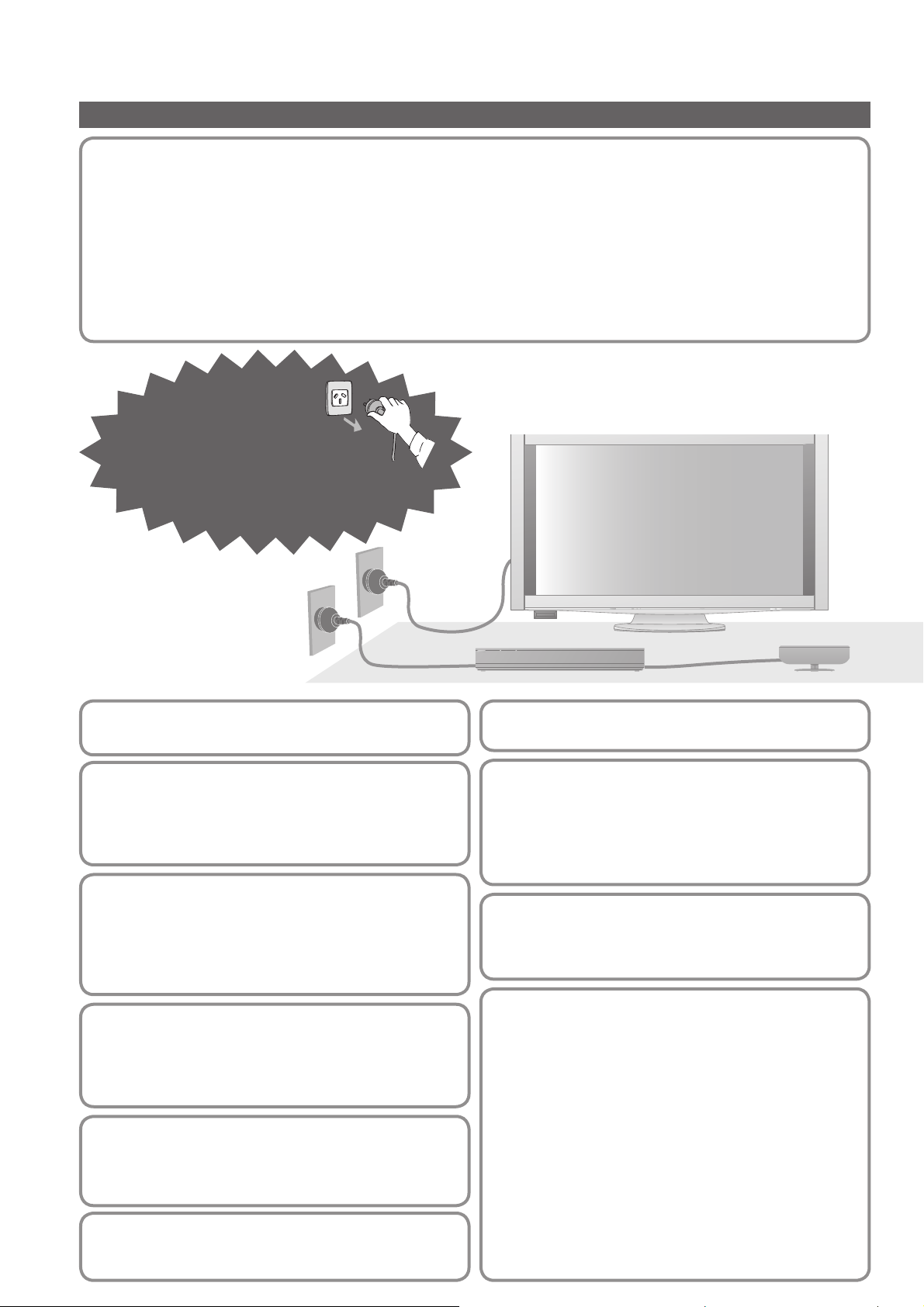
Handling the mains plug and lead
Insert the mains plug fully into the socket outlet. If the mains plug is loose, it could generate heat and cause fire.
●
●
Ensure that the mains plug is easily accessible.
●
Ensure the earth pin on the mains plug is securely connected to prevent electrical shock.
●
Do not touch the mains plug with a wet hand. This may cause electrical shock.
●
Do not damage the mains lead. A damaged lead may cause fire or electrical shock.
Do not move the TV with the lead plugged in the socket outlet.
●
●
Do not place a heavy object on the lead or place the lead near a high-temperature object.
●
Do not twist the lead, bend it excessively, or stretch it.
●
Do not pull on the lead. Hold onto the mains plug body when disconnecting lead.
●
Do not use a damaged mains plug or socket outlet.
If you find any
abnormality, remove
the mains plug
immediately!
4
AC 220 - 240 V
50 / 60 Hz
Power source
This TV is designed to operate on AC 220 - 240 V, 50 / 60 Hz.
●
Do not remove covers
NEVER modify the TV yourself
High-voltage components may cause serious electrical shock.
Have the TV checked, adjusted, or repaired at your
●
local Panasonic dealer.
Keep liquids away from the TV
To prevent damage which may result in fire or shock hazard,
●
do not expose this appliance to dripping or splashing.
Do not place containers with water (flower vase,
●
cups, cosmetics, etc.) above the TV, including on
shelves above, etc.
Do not expose to direct sunlight and
other sources of heat
Avoid exposing the TV to direct sunlight and other
●
sources of heat. To prevent fire never place any type
of candle or naked flame on top or near the TV.
Avoid exposing the TV to high
atmospheric moisture (such as tropical
rain) or night time dew condensation
This TV is designed and manufactured for indoor use only.
●
Do not place foreign objects inside the TV
Do not allow any objects to drop into the TV through
●
the air vents. Fire or electrical shock may result.
Do not place the TV on sloped or unstable surfaces
The TV may fall off or tip over.●
Use only the dedicated pedestals /
mounting equipment
Using an unapproved pedestal or other fixtures may
●
make the display unit unstable, risking injury. Be sure
to ask your local Panasonic dealer to perform setup.
Use approved pedestals / mounts (p. 8).
●
Do not allow children to handle SD Card
As with any small object, SD Cards can be swallowed
●
by young children. Please remove SD Card immediately
after use and store out of reach of children.
Radio waves
Do not place this TV in any medical institutions or
●
locations with medical devices. Radio waves from
this TV may interfere with the medical devices and
cause accidents due to the malfunction.
Do not use this TV near any automatic control devices
●
such as automatic doors or fire alarms. Radio waves
from this TV may interfere with the automatic control
devices and cause accidents due to the malfunction.
Keep the RF remote control, tuner box and wireless
●
unit away at least 22 cm from the location where a
cardiac pacemaker is implanted. Radio waves from this
TV may interfere with the operation of the pacemaker.
Do not disassemble RF remote control, tuner box
●
or wireless unit. It may cause troubles such as
difficulties in communication.
Page 6
Important Installation Notices
Install TV on a stable surface
If a television is not positioned in a sufficiently stable location, it can be potentially hazardous due to falling.
Many injuries, particularly to children, can be avoided by taking simple precautions such as:
●
Using cabinets or stands recommended by the manufacturer of the television.
●
Only using furniture that can safely support the television.
●
Ensuring the television is not overhanging the edge of the supporting furniture.
●
Not placing the television on tall furniture (for example, cupboards or bookcases) without anchoring both the
furniture and the television to a suitable support.
●
Not standing the televisions on cloth or other materials placed between the television and supporting furniture.
●
Educating children about the dangers of climbing on furniture to reach the television or its controls.
When cleaning the TV, remove the mains plug
●
Cleaning an energized TV may cause electrical shock.
When the TV is not going to be used for a long period of time, remove the mains plug
●
This TV will still consume some power even in the Off mode, as long as the mains plug is still connected to a live socket outlet.
Transport only in upright position
●
Transporting the display unit with its display panel facing upward or downward may cause damage to the internal circuitry.
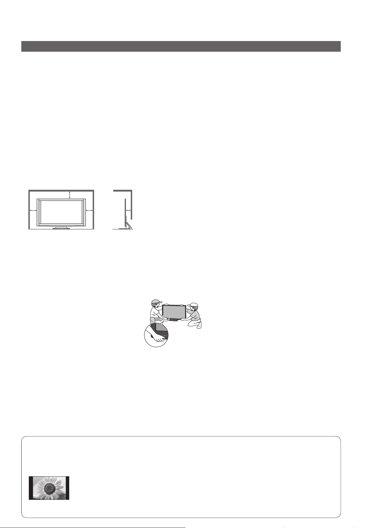
Allow sufficient space around the display unit for radiated heat
Minimum distance
When using the pedestal, keep the space between the bottom of the
●
display unit and the surface where the display unit is set.
●
3
In case of using Wall-hanging bracket, follow the manual of it.
(cm)
10
10
10
Do not block the rear air vents
●
Blocked ventilation by newspapers, table cloths, curtains, etc. may cause overheating, fire or electrical shock.
Do not expose your ears to excessive volume from the headphones
●
Irreversible damage can be caused.
Display panel is made of glass. Do not apply strong force or impact to the display panel.
This may cause damage resulting in injury.
●
The display unit is heavy. Handle the display unit by 2 or more people. Support as
shown to avoid injury by the display unit tipping or falling.
When the wireless receiver is attached,
●
avoid holding over it.
Auto power standby function
If no signal is received and no operation is performed in Analogue TV mode for 30 minutes, the TV will
●
automatically go to standby mode.
●
The TV will automatically go to Standby mode if there are no signal and no operation between the display unit
and the tuner box for a while.
Tuner Box - after 1 minute
Display Unit - after 10 minutes
Keep the TV away from these types of equipment
Electronic equipment
●
In particular, do not place video equipment near the TV. Electromagnetic interference may distort images / sound.
●
Equipment with an infrared sensor
This TV also emits infrared rays. This may affect operation of other equipment.
Do not display a still picture for a long time
This causes the image to remain on the plasma screen (“image retention”).
This is not considered a malfunction and is not covered by the warranty.
Typical still images
Programme number and other logos
●
●
Image displayed in “4:3” mode
●
Video game
●
Computer image
To prevent image retention, contrast is lowered automatically after a few minutes if no signals are sent or no
operations are performed. (p. 55)
5
Page 7
Maintenance
First, remove the mains plug from the socket outlet.
Display panel
Regular care: Gently wipe the surface clean of dirt by using a soft cloth.
Major contamination: Wipe the surface clean using a soft cloth dampened with clean water or diluted neutral detergent
(1 part detergent to 100 parts water). Then, using a soft dry cloth, evenly wipe the surface clean until it is dry.
Caution
The surface of the display panel has been specially treated and may be easily damaged.
●
Do not tap or scratch the surface with your fingernail or other hard object.
●
Take care not to subject the surface to insect repellent, solvent, thinner, or other volatile substances. This may
degrade surface quality.
Cabinet, Pedestal, Tuner Box
Regular care: Wipe the surface clean using a soft dry cloth.
Major contamination: Dampen a soft cloth with clean water or water containing a small amount of neutral detergent.
Then, wring the cloth and wipe the surface clean with it. Finally, wipe the surface clean with a dry cloth.
Caution
●
Take care not to subject the surfaces to detergent. A liquid inside these units could lead to product failure.
●
Take care not to subject surfaces to insect repellent, solvent, thinner, or other volatile substances. This may
deteriorate the surface by peeling the paint.
●
Do not allow the cabinet and pedestal to make contact with a rubber or PVC substance for a long time.
Mains plug
Wipe the mains plug with a dry cloth at regular intervals. Moisture and dust may lead to fire or electrical shock.
Wireless Unit (Receiver and Transmitter)
Wipe the glossy surface of the receiver and the transmitter gently with the cleaning cloth (included).
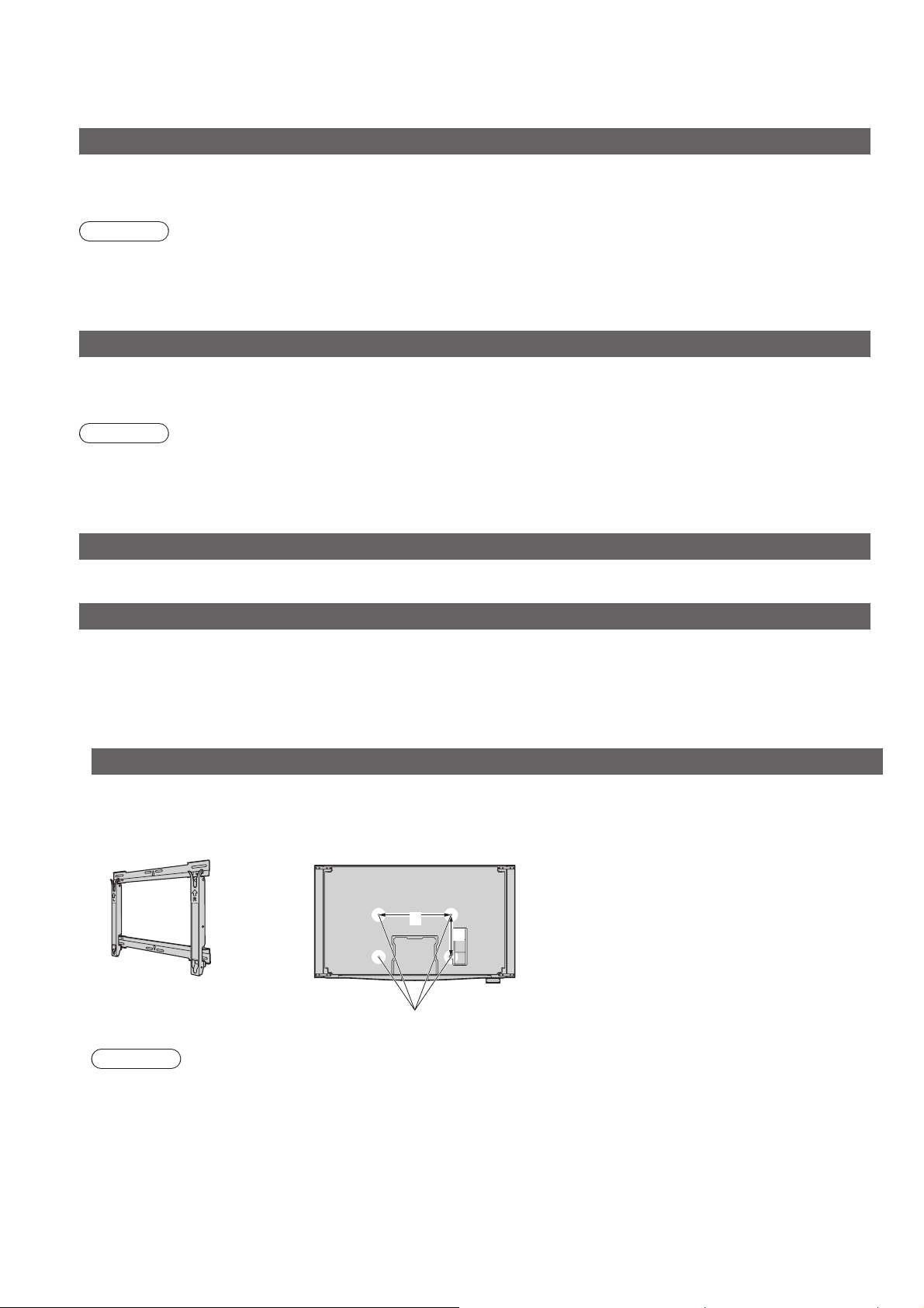
Options
Optional accessories
Please contact your nearest Panasonic dealer to purchase the recommended wall-hanging bracket. For additional
details, please refer to the wall-hanging bracket installation manual.
Wall-hanging bracket
TY-WK5P1SW●
Rear of the Display Unit
a
b
a: 516 mm / b: 300 mm●
6
Holes for wall-hanging
bracket installation
Caution
In order to maintain the TV’s performance and safety, be absolutely sure to ask your dealer or a licenced
●
contractor to secure the wall-hanging brackets.
●
Carefully read the instructions accompanying wall-hanging bracket, and be absolutely sure to take steps to
prevent the display unit from falling off.
●
Handle the display unit carefully during installation since subjecting it to impact or other forces may cause product
damage.
●
Take care when fixing wall brackets to the wall. Always ensure that there are no electrical cables or pipes in the
wall before hanging bracket.
●
To prevent fall and injury, remove the display unit from its fixed wall position when it is no longer in use.
Page 8
Accessories
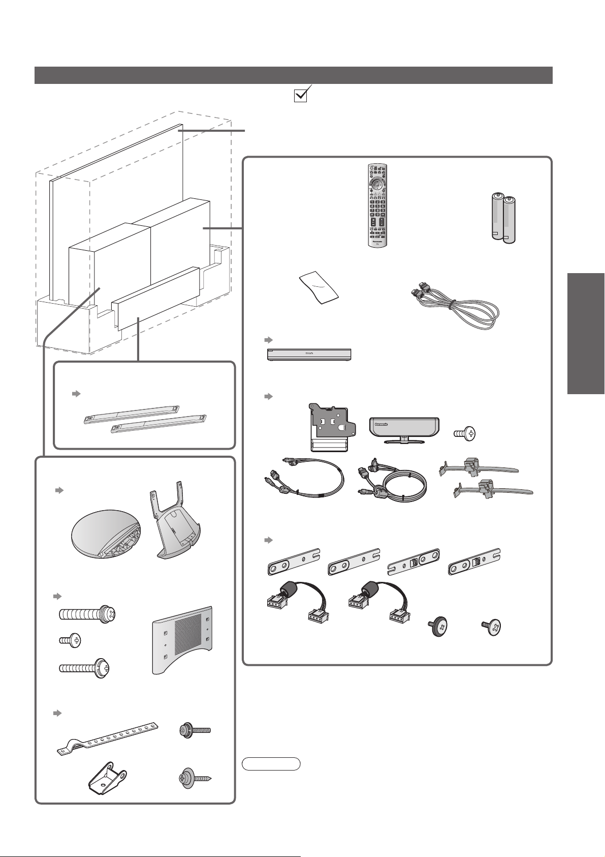
Standard accessories
Check if you have the accessories and items shown
Display Unit
□
TH-P54Z1AM
●
Remote control
□
N2QBYB000006
●
ヵヷ
モヷ
Batteries for the
□
Remote control (2)
R6 (AA)
●
□
Pedestal
□
TBLX0115
●
p. 8
Speaker (2)
SP-54Z1A
●
p. 10
Cleaning cloth
□ HDMI cable
Tuner Box
□
TU-Z100AR
●
p. 12 and p. 13
Wireless Unit (Receiver and Transmitter)
□
TU-WH1A
●
p. 13
Speaker installation kit
□
TXFKR01DKUA
●
p. 10
□
K1HY19YY0004
●
(2)
Guide
Quick Start
Accessories
Maintenance / Options
Pedestal installation kit
□
TXFBL01JUUJ
●
p. 8
(2)
(4)
(4)
□
Fall-prevention parts
●
TXFKL01JUUJ
p. 11
(8) (8)
Operating Instructions with Warranty statement□
Caution
This product contains possibly dangerous parts (such as plastic
●
bags), that can be breathed in or swallowed by young children
accidentally. Keep these parts out of reach of young children.
7
Page 9
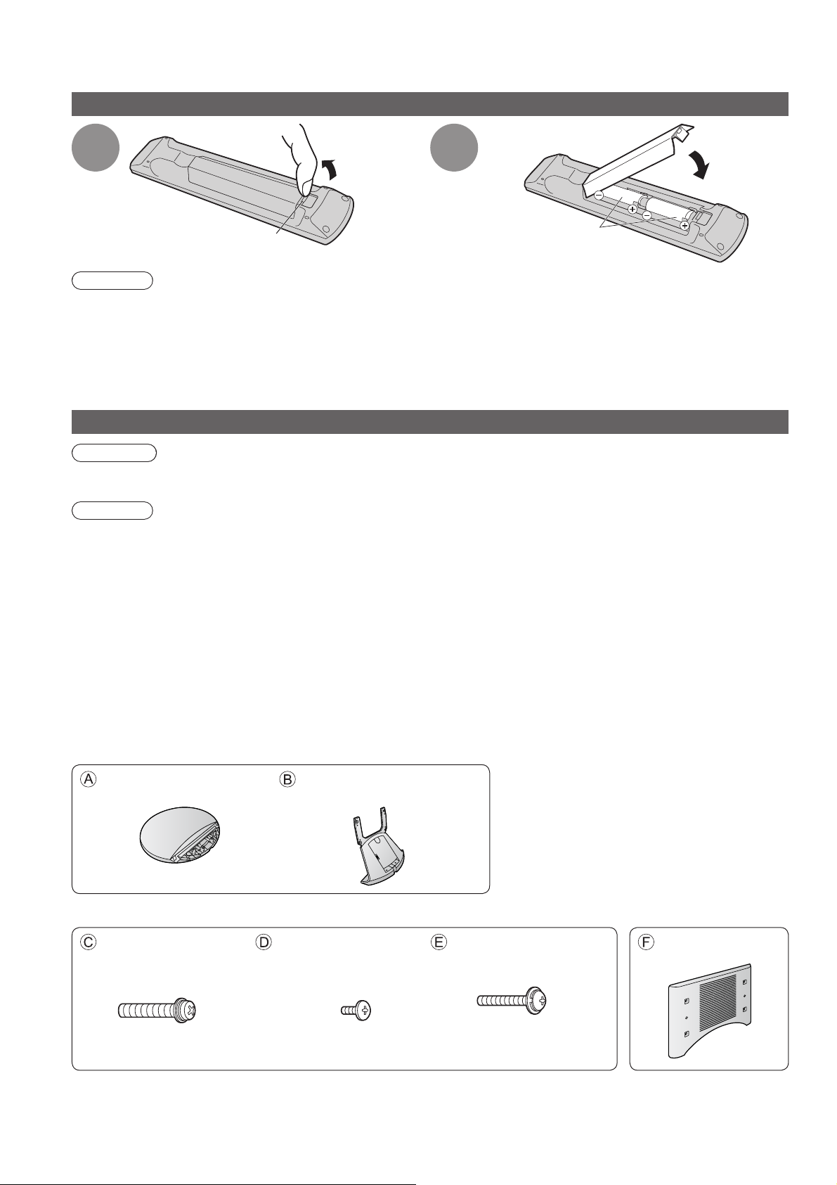
Accessories
Installing remote’s batteries
Pull
open
1
2
Close
Hook
Caution
Incorrect installation may cause battery leakage and corrosion, resulting in damage to the remote control.
●
●
Do not mix old and new batteries.
●
Do not mix different battery types (such as alkaline and manganese batteries).
●
Do not use rechargeable (Ni-Cd) batteries.
●
Do not burn or breakup batteries.
Batteries must not be exposed to excessive heat such as sunshine, fire or the like.
Note the correct
polarity (+ or -)
Attaching the pedestal
Warning
Do not disassemble or modify the pedestal.
●
Otherwise the display unit may fall over and become damaged, and personal injury may result.
Caution
Do not use any other TV and displays.
Otherwise the TV may fall over and become damaged, and personal injury may result.
●
Do not use the pedestal if it becomes warped or physically damaged.
●
If you use the pedestal while it is physically damaged, personal injury may result. Contact your nearest Panasonic
dealer immediately.
During set-up, make sure that all screws are securely tightened.
●
If insufficient care is taken to ensure screws are properly tightened during assembly, the pedestal will not be
strong enough to support the display unit, and it might fall over and become damaged, and personal injury may
result.
Ensure that the display unit does not fall over.
●
If the display unit is knocked or children climb onto the pedestal with the display unit installed, the display unit
may fall over and personal injury may result.
Two or more people are required to install and remove the display unit.
●
If two or more people are not present, the display unit may be dropped, and personal injury may result.
Pedestal
8
Base
TBLA0460●
Pedestal installation kit
Assembly screw (2)
(Silver)
XYN8+F30FN●
M8 × 30 M4 × 10 M5 × 25
Frame
TBLA0466●
Assembly screw (4)
(Black)
XSB4+10FNK●
Assembly screw (4)
(Black)
THEL062N●
Holder cover
TBLB3416●
Page 10
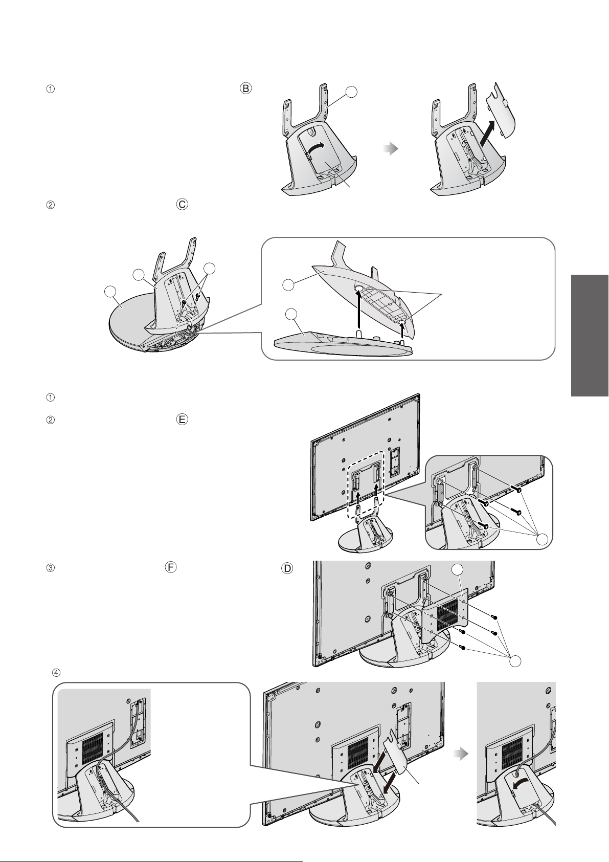
Assembling the pedestal
Remove the cable cover from the frame .
The cable cover will be used again after the
●
pedestal is attached to the display unit.
Use the assembly screws to fasten securely.
Make sure that the screws are securely tightened.
●
●
Be careful not to scratch the surface (part with gloss finish) of the base during assembly.
B
Cable cover
B
A
C
Securing the Display Unit
Slide the pedestal frame posts into the brackets on
the rear of the display unit.
Use the assembly screws to fasten securely.
Make sure that the screws are securely tightened.●
B
Hole for the
base installation
A
Guide
Quick Start
Accessories
E
Attach the holder cover with assembly screws .
Make sure that the screws are securely tightened.●
Attach the cable cover.
Place a cable in
●
the groove as
necessary and
attach the cable
cover.
The lower part
of the groove is
separated in right
and left. Use the
one suitable for
you.
F
D
Cable cover
9
Page 11
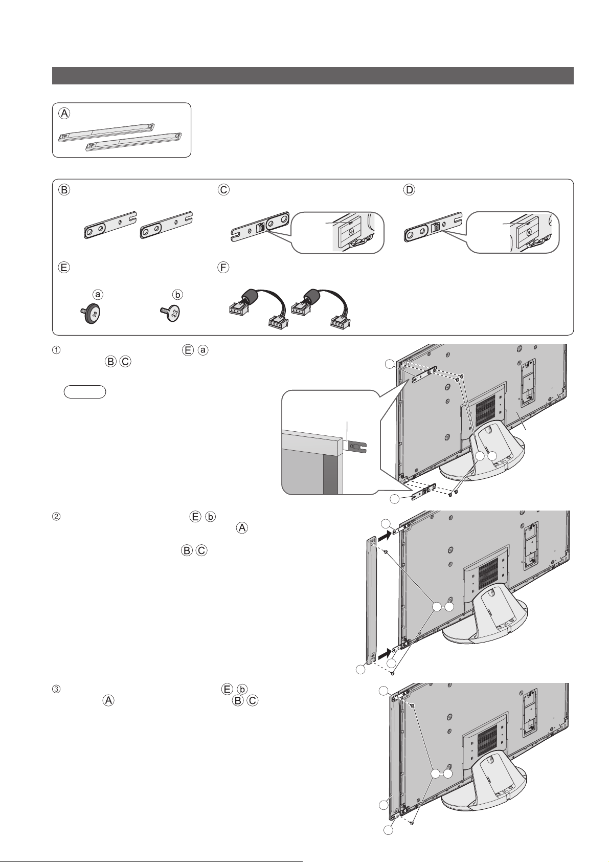
Accessories
Attaching the Speakers
Speaker
Speaker (2)
Speaker installation kit
Mounting bracket-[Top] (2)
TXFKR04DLUJ●
Assembly screw
TXFXY01DLUJB●
(8)
Use the assembly screws - to fasten the mounting
brackets to the rear of the display unit securely.
Make sure that the screws are securely tightened.
●
(8)
Mounting bracket-[Lower right]
TXFKR02JXUE●
Hook
Speaker cable (2)
TXJ/SPDKUU-1●
Note
Loosen these screws to
●
adjust the gap between the
speaker and the display unit
as necessary.
Ensure that the silver
part is facing the front
Mounting bracket-[Lower left]
TXFKR03JXUE●
Hook
B
E-a
-
Display Unit
Insert the assembly screws - temporarily in the
screw outermost holes of the speaker and place the
temporarily inserted screws into the counter sunk holes
on the mounting brackets .
Use another two assembly screws - to fasten the
speaker to the mounting brackets .
C
B
E-- b
C
A
B
E-- b
10
A
C
Page 12
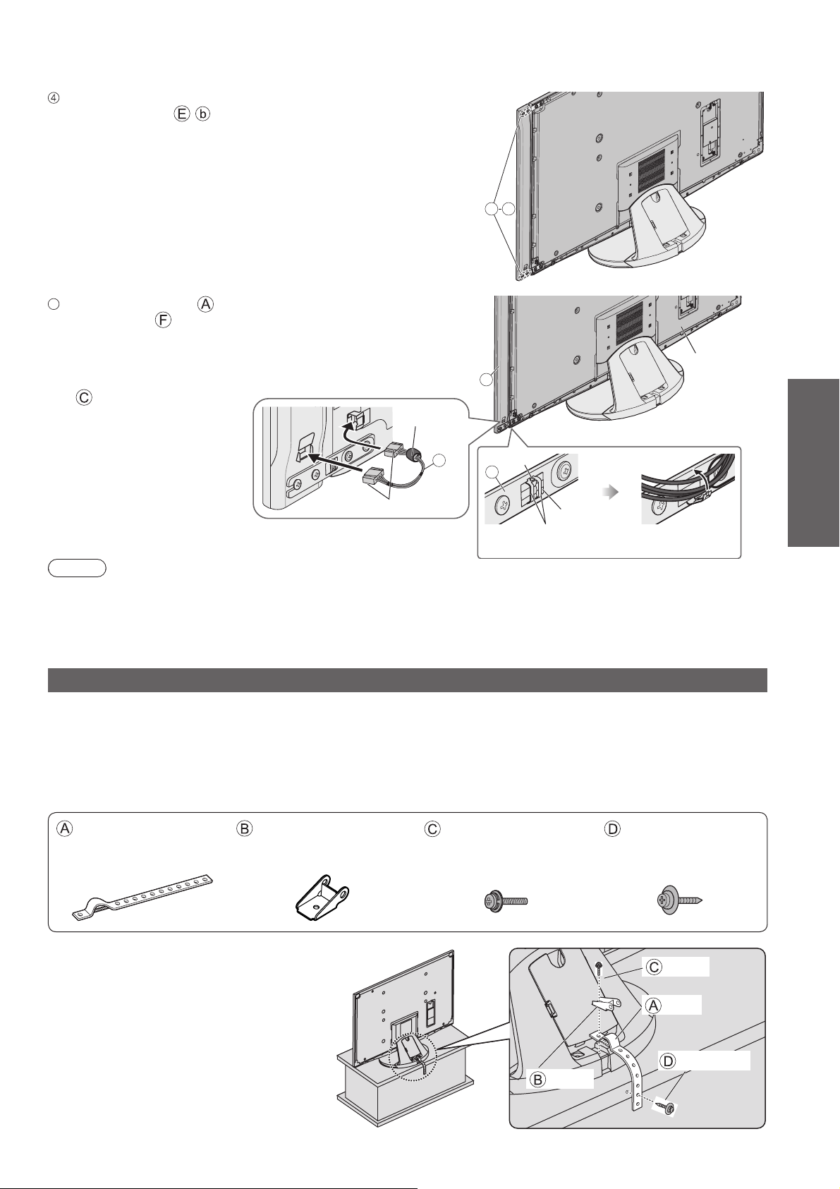
Adjust the speaker position and make sure that the
assembly screws - are securely tightened.
5
Connect the speaker and the display unit with the
speaker cable .
Insert the terminal firmly.
●
●
Connect the terminal near the ferrite core to the display
unit.
●
Fix the cable with the clamper on the mounting bracket
.
E b
Display Unit
A
Ferrite core
F
Terminals
Hook
C
Push here to
remove the hook
Clamper
Fix the cable
Note
Fix the other side speaker in the same way.
●
●
There will be a gap between the display unit and the speaker.
●
Do not hold the speaker part to transport the display unit.
Preventing the TV from falling over
This TV could fall over if it's pushed, pulled or knocked down.
We therefore recommend the TV is secured to the base as illustrated.
This measure is designed to reduce the risk of injury from a falling TV. However, it cannot guarantee protection in
●
all cases.
Fall-prevention parts
TXFKL01JUUJ
●
Band Clamp Screw Wood screw
TKLA4301● TKLA4201●
XYN4+F15FNK●
THEJ019N●
Guide
Quick Start
Accessories
Securing to a base
Fix pedestal and base together with band.
Clamp
This image is for illustrative purposes only.
Screw
Band
Wood screw
11
Page 13
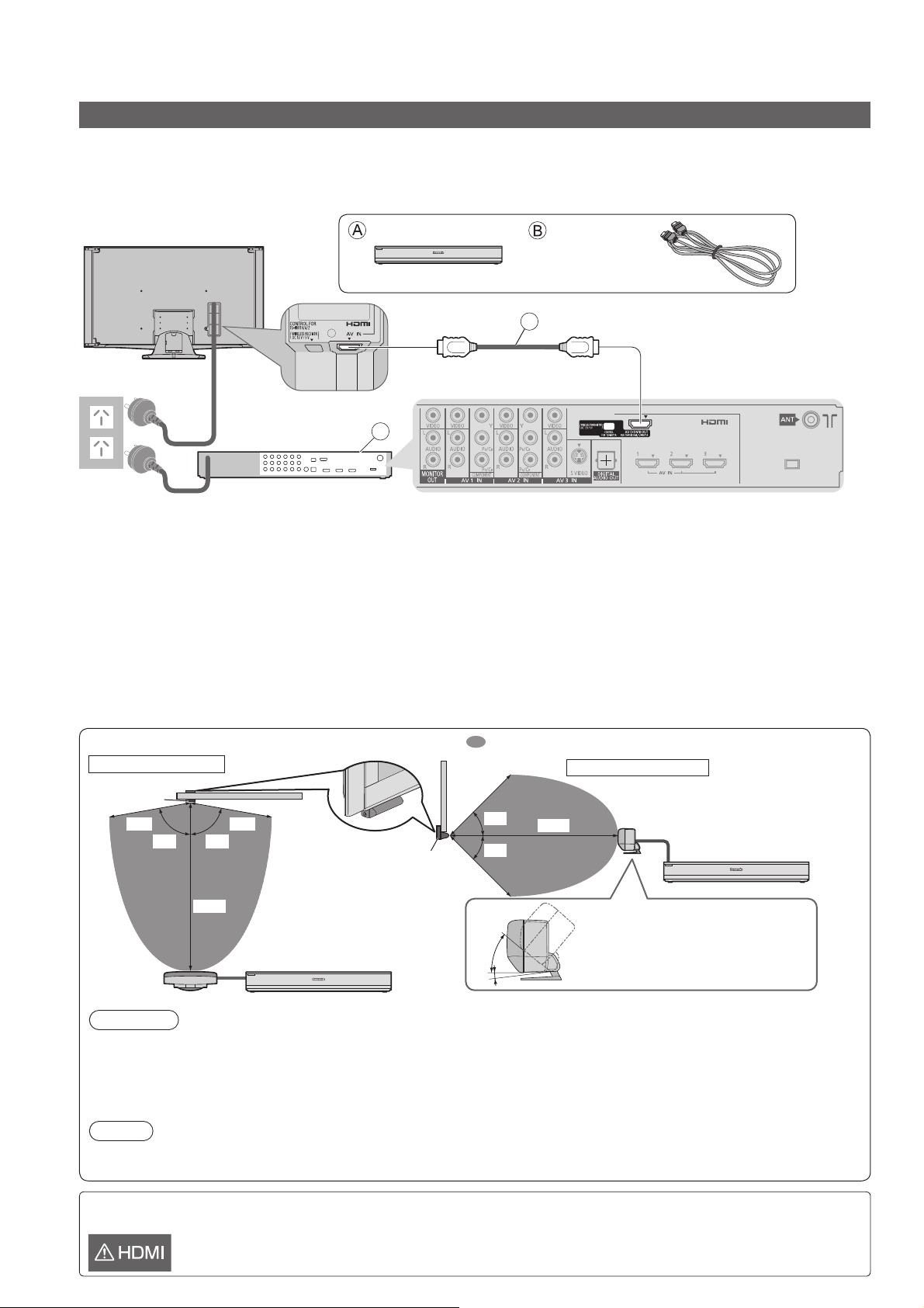
Basic Connection
Connecting the Display Unit and the Tuner Box
Please ensure that the display unit and the tuner box are disconnected from the mains sockets before attaching or
disconnecting any leads.
Wired connection
If you are going to place the tuner box close to the display unit, it is recommended to connect them using supplied HDMI cable.
●
Rear of the Display Unit
AC 220 - 240 V
50 / 60 Hz
Mains
lead
Rear of the Tuner Box
Tuner Box
A
HDMI cable
3.0 m
B
Wireless connection
You can place the tuner box and the display unit in a flexible way using the wireless unit (not using any cables
between the display unit and the tuner box). If you choose to use the wireless connection between the display
unit and the tuner box, ensure that the wireless transmitter and the wireless receiver are positioned to face
each other without any obstructions.
The wireless unit uses 60 (59.40 - 61.56) GHz frequency band. Do not use the wireless unit near the equipment
●
using the same frequency band to avoid the interference.
●
It may take a while to change the input mode when using the wireless unit. To resolve this, use supplied HDMI
cable to connect the display unit and the tuner box.
●
Picture and sound may be interrupted or the TV may not be operated properly depending on the setting place
of the wireless transmitter or obstacles (furniture, AV equipment, rack, rack door, etc.) between the wireless
transmitter and the wireless receiver. To resolve this, change the installation layout without any obstacles between
the wireless transmitter and the wireless receiver.
Transmission range of the Wireless Unit : Available area to place the wireless transmitter
View from the top
Wireless
Receiver
80° 80°
10 m
Wireless
Transmitter
Display
5 m5 m
Tuner Box
Unit
Wireless
Receiver
Display Unit
5 m
45°
45°
5 m
40°
5°
View from the side
10 m
Adjust the angle of the
●
wireless transmitter to face
the wireless receiver.
Wireless
Transmitter
Tuner Box
Caution
Do not place the wireless unit in the following locations to avoid poor signal condition or TV failures.
●
Location subject to be high temperature (near the heater, etc.)
•
Location with poor air circulation (at the end of a closed rack, etc.)
•
Keep the wireless unit away from the devices such as wireless LAN, microwaves, mobile phones or other
●
electric equipment to avoid radio wave interference. Otherwise malfunction or slow response may occur.
Note
The range may be shortened depending on the obstacles, the surrounding environment or building structure.
●
●
Ensure the wireless transmitter is facing the wireless receiver.
12
If the display unit is connected to external equipment other than the supplied tuner box by using HDMI cable, the
following icon will be displayed on the screen.
Some functions may not be available depending on the connected equipment.●
Page 14
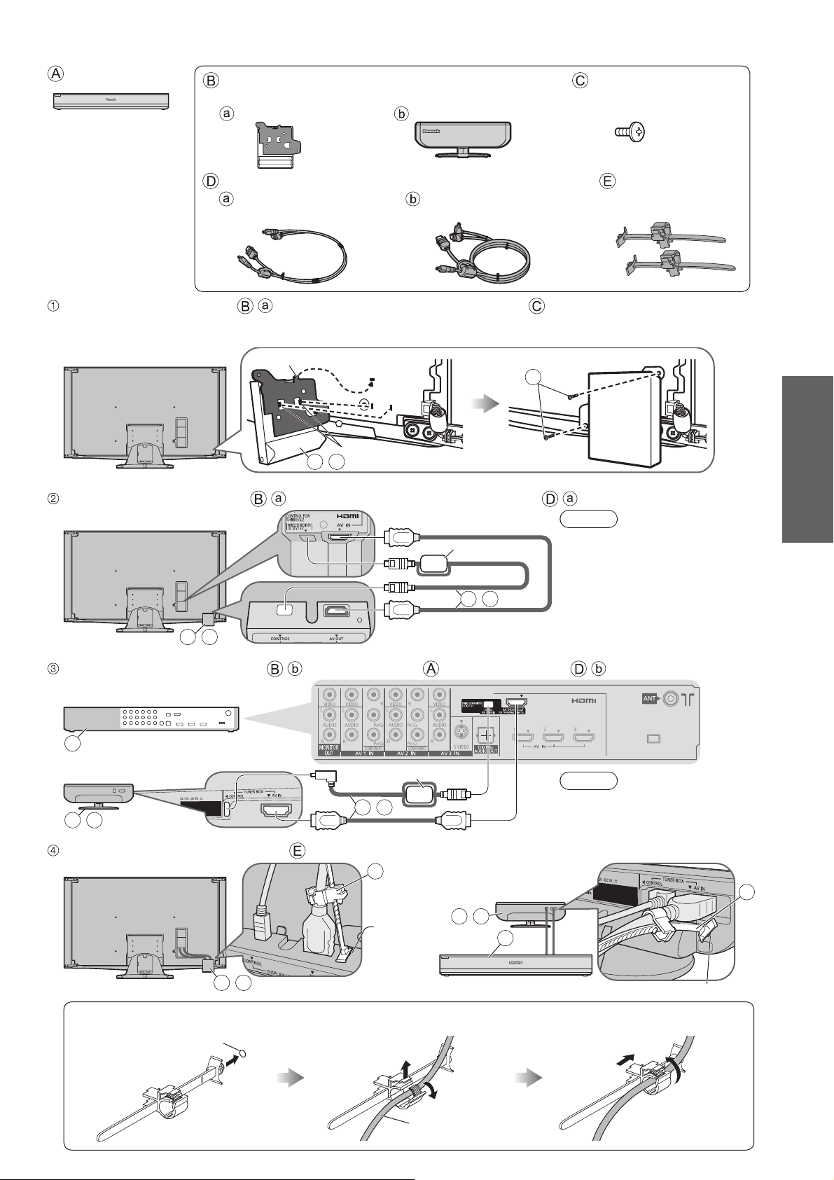
Tuner Box
Wireless Unit (Receiver and Transmitter)
TZTWH01JSUA●
Wireless Receiver Wireless Transmitter
Assembly screw (2)
TXFXY01JSUJB●
M4 × 10
Exclusive cable for Wireless Unit Cable clamper (2)
For Wireless Receiver
TXFMM02JSUE●
For Wireless Transmitter
TXFMM03JSUE●
TMME364●
0.5 m 1.0 m
Attach the wireless receiver - to the display unit with assembly screws .
Insert the top tab into the groove of the display unit, and then insert the front tabs.
●
●
Make sure that the screws are securely tightened.
Rear of the Display Unit
Connect the wireless receiver - and the display unit with exclusive cable - .
Rear of the Display Unit
B-a
Connect the wireless transmitter - and the tuner box with exclusive cable - .
Top tab
B-a
Front tab
Ferrite core
D-a
C
Note
Connect the terminal near
●
the ferrite core to the display
unit.
Guide
Quick Start
Basic Connection
Rear of the Tuner Box
A
Rear of the
Wireless Transmitter
B-b
Bind the cables with cable clampers .
Rear of the Display Unit
B-a
Insert the cable clamper in a
hole
Hole
Ferrite core
D-b
E
Hole for
cable clamper
Open the clamper and insert
the cable
Rear of the
Wireless Transmitter
B-b
Note
Connect the terminal near
●
the ferrite core to the tuner
box.
E
A
Hole for cable clamper
Close the clamper and slide up
to fix the terminal securely
Cable
13
Page 15
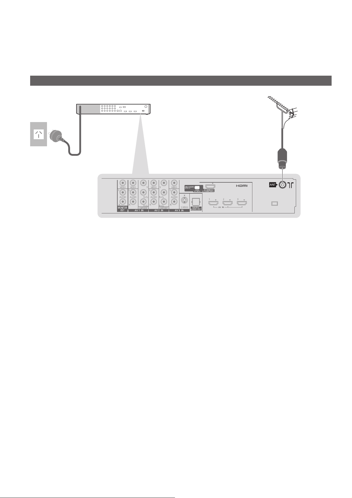
Basic Connection
External equipment and cables shown are not supplied with this TV.
Please ensure that the tuner box is disconnected from the mains socket before attaching or
disconnecting any leads.
Read the manual of the equipment too.
●
Connecting the Tuner Box and aerial
AC 220 - 240 V
50 / 60 Hz
Mains lead
Rear of the Tuner Box
RF cable
Terrestrial
aerial
For digital cable,
●
digital terrestrial
and analogue
broadcasts
14
Page 16
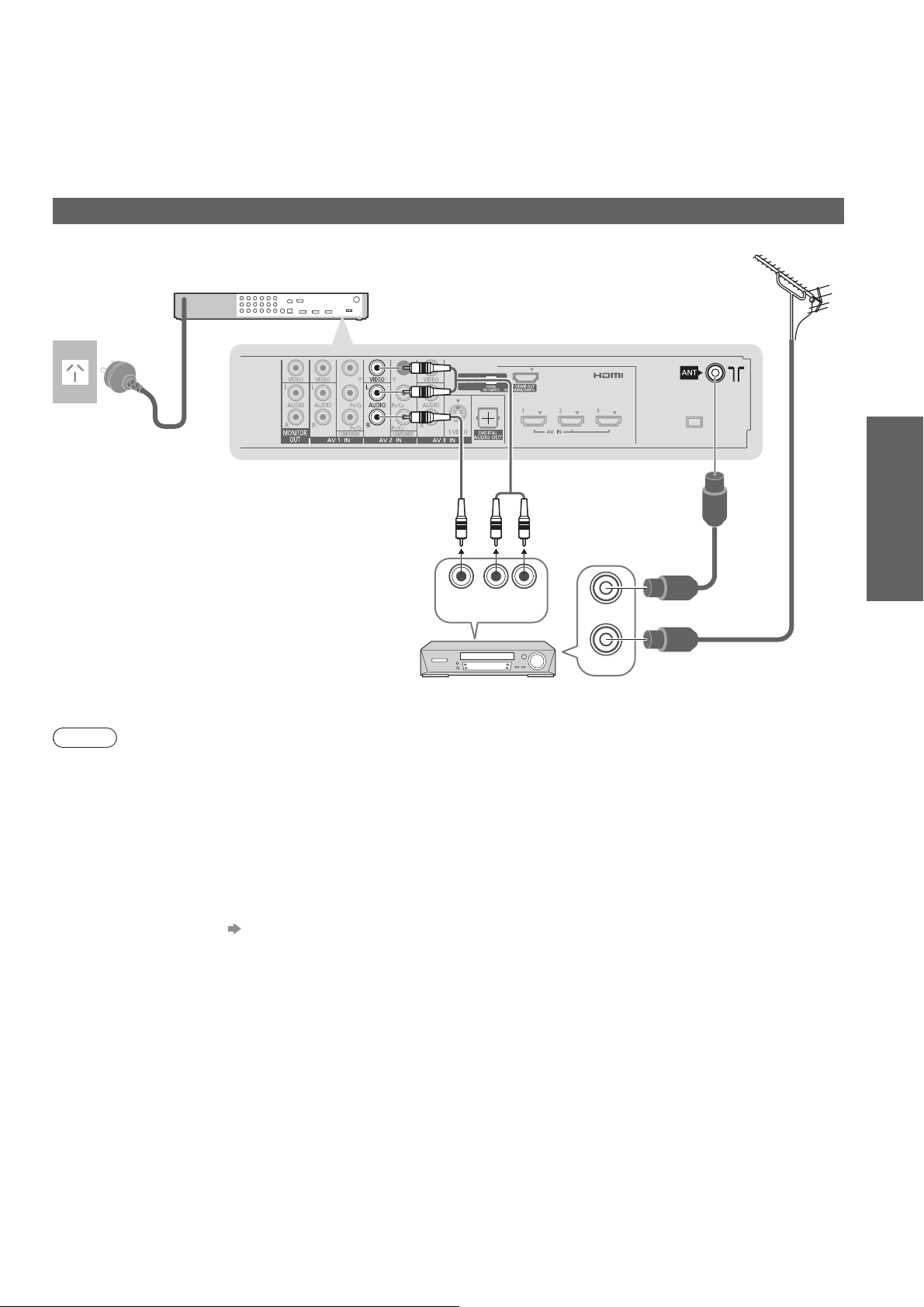
AC 220 - 240 V
50 / 60 Hz
Mains lead
Connecting the Tuner Box and DVD Recorder / VCR
Terrestrial
aerial
Rear of the Tuner Box
RCA cable
Guide
Quick Start
OUT
AUDIO
OUT
RF OUT
RF IN
RF cable
RF cable
VIDEO
DVD Recorder or VCR
Note
Do not put the RF cable close to the mains lead to avoid noise.
●
●
Do not place the RF cable under the tuner box.
●
To obtain optimum quality picture and sound, an aerial, the correct cable (75 Ω coaxial) and the correct
terminating plug are required.
●
If a communal aerial system is used, you may require the correct connection cable and plug between the wall
aerial socket and the TV.
●
Your local Television Service Centre or dealer may be able to assist you in obtaining the correct aerial system for
your particular area and the accessories required.
●
Any matters regarding aerial installation, upgrading of existing systems or accessories required, and the costs
incurred, are the responsibility of you, the customer.
●
VIERA Link connection p. 44
●
Read the manual of the equipment, too.
Basic Connection
15
Page 17
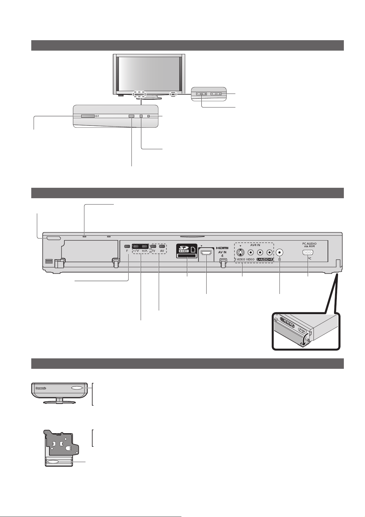
Identifying Controls
Display Unit
Power LED
Standby: red
●
Mains power On / Off switch
Turn the display unit On or Off.
●
When turning Off the display
unit, tuner box will also be
turned to Standby mode after
1 min.
Standby switch
Turn the tuner
●
box on or off to
standby mode
Remote control signal receiver
Do not place any objects between the TV remote control signal receiver and remote control.●
Power LED
Standby: red
●
On: green
When using the remote control, indicates the TV has received a command.
●
On: green
When using the remote control, indicates
●
the TV has received a command.
C.A.T.S. (Contrast Automatic Tracking System) sensor
Senses brightness to adjust picture quality when
●
“Eco Mode” in the Picture Menu is set to “On” (p. 30)
Tuner Box
Selects channel in sequence
Volume Up / Down
Function select
Volume / Contrast / Brightness /
●
Colour / Sharpness /
Tint (NTSC mode) / Bass / Treble /
Balance / Auto Tuning (p. 30 and p. 31)
Remote Pairing (p. 19)
●
Wireless Transmitter
On and no communication : Red
On and communication state good : Green
On and communication state not good : Orange
Indicates malfunction : Red (blinking)
Wireless Receiver
On and no communication : Red
On and communication state good : Green
Indicates malfunction : Red (blinking)
SD Card slot
(p. 41)
HDMI4 terminal
(p. 50)
Changes the input mode
Change the channel up/down. When a
function is displayed, press up/down to adjust
the setting of the selected function. When in
standby mode, switches TV on.
AV4 terminals
(p. 50)
Wireless Unit
PC terminal
(p. 50)
Headphones jack
(p. 50)
16
When the orange LED is lit, check the connection and transmission range. (p.12 and P.13)
●
●
When the red LED is blinking, turn the power of the tuner box and display unit off and then on again.
If the problem is not resolved, consult your local Panasonic dealer.
Page 18
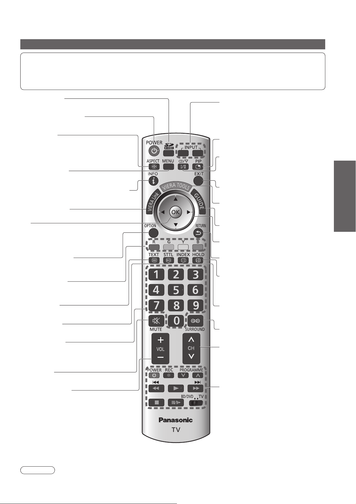
Remote control
This remote control is RF (Radio Frequency) remote control.
Signals are sent in virtually every direction, so that you can operate the TV even if the remote control is not
facing the display unit or the tuner box. In addition, as the radio waves reflect on walls or other obstacles, the
remote control is operable even there are obstacles between the remote control and the tuner box.
This remote control uses 2.4 GHz frequency band.●
SD Card (p. 41)
Switches to SD Card viewing mode
●
Standby On / Off switch
Switches TV On or Off standby●
Aspect (p. 22)
Changes aspect ratio from Aspect Selection
●
list
Also possible by pressing this button
●
repeatedly until you reach the desired aspect
Main Menu (p. 29)
Press to access Picture, Sound and
●
Setup Menus
Channel / Programme Information
Displays channel and programme
●
information
VIERA Link (p. 46)
Accesses VIERA Link Menu
●
OK
Confirms selections and choices
●
●
Press after selecting channel positions
to quickly change channel
Option Menu (p. 21)
Easy setting for sound options
●
(p. 21)
ヵヷ
モヷ
Input mode selection
TV - swithes to Digital TV / Analogue TV
●
mode (p. 20)
AV - switches to AV input mode from Input
●
Selection list (p. 26)
Multi window (p. 22)
Displays two windows at once
●
Stereo / Bilingual Sound Selection (p. 52)
Changes the sound track when more than
●
two choices are available
(Digital TV mode) (p. 21)
Exit
Returns to the normal viewing screen●
VIERA TOOLS (p. 49)
Displays functions of the linked equipment
●
& SD card
Guide (p. 23)
Displays TV Guide
●
Cursor buttons
Makes selections and adjustments●
Return
Returns to the previous menu / page●
Guide
Quick Start
Coloured buttons
Used for the selection, navigation and
●
operation of various functions
Teletext (p. 24)
Switches to teletext mode
●
Subtitles (p. 20)
Displays subtitles
●
Numeric buttons
Changes channel and teletext pages
●
●
When in Standby mode, switches TV On
Sound Mute
Switches sound mute On or Off●
Volume Up / Down
Transmission range
Use the RF remote control within the range of 7 m from the tuner box.
The range may be shortened depending on the obstacles, the surrounding environment or building structure.
Hold
Freeze / unfreeze picture (p. 20)
●
●
Holds the current teletext page (teletext
mode) (p. 24)
Index (p. 24)
Returns to the teletext index page
●
(teletext mode)
Surround (p. 30)
Switches Surround sound
●
Channel Up / Down
Selects channel in sequence●
VCR / DVD Panasonic equipment
operations (p. 27)
Caution
Keep the remote control away from the devices such as wireless LAN, microwaves, mobile phones or other
●
electric equipment to avoid radio wave interference. Otherwise malfunction or slow response may occur.
Identifying Controls
17
Page 19

Auto Tuning
Search and store TV channels automatically.
These steps are not necessary if the setup has been completed by your local dealer.
Please complete preparations and setup of all units before starting Auto Tuning. (p. 8 - 13)
●
●
Please complete connections (p. 14 and p. 15) and settings (if necessary) of the connected equipment before
starting Auto Tuning. For details of settings for the connected equipment, read the manual of the equipment.
Plug the display unit and tuner box into mains
1
2
ヵヷ
モヷ
socket, and turn on the display unit
It takes a few seconds to start.●
Pair the remote control with the TV
(simultaneously)
Press “OK” and “1” simultaneously
Remote Pairing
Press both "OK" and "1" button for
about 3 seconds until this screen will
disappear
EXIT
●
for more than 3 seconds to make
the remote control usable.
●
You can pair the remote control
again after Auto Tuning.
“Pairing Remote Control”
(p. 19)
3
4
5
6
Select your area
Select State / Territory
New South Wales / Australian Capital Territory
Victoria
Queensland
South Australia
Western Australia
Northern Territory
Tasmania
Select Auto Scan Type
Auto Scan Type
All Channels
Digital TV Channels only
Start Auto Tuning
Auto Tuning
Digital TV Scan CH 6 69
Analogue TV Scan CH 0
This will take about 6 minutes.
RF Ch Channel Name Type Quality
62
CBBC Channel Digital TV 10
62 BBC Radio Wales Digital TV 10
62 E4 Digital TV 10
62 Cartoon Nwk Digital TV 10
29
33
Digital TV: 4 Analogue TV: 2
EXIT
RETURN
Searching
Analogue TV
Analogue TV
-
-
Auto Tuning will start to search for
●
75
TV channels and store them.
The sorted channel order
depends upon the TV signal,
the broadcasting system and
reception conditions.
Select the viewing environment
Please select your viewing environment.
Home Shop
“Home” is the recommended mode for
●
viewing at home. Select “Home” for optimal
picture / power consumption.
“Shop” is for in-store display.
Home:
Shop:
“Viewing Mode” is set as “Normal”. (p. 30)
“Viewing Mode” is set as “Dynamic”. (p. 30)
select
set
select
select
set
Auto Tuning is complete
18
If you select “Shop” by mistake
Return to the “Home” or “Shop”
Selection menu
Automatic Demo
Off On
Once you press the OK button in this menu,
●
the TV is set to Shop mode.
Please reset all settings to set to “Home” mode.
“Shipping Condition” (p. 38)
RETURN
Select “Home”
Please select your viewing environment.
Home Shop
select
set
Auto Tuning is complete
Page 20

Using the On-Screen Displays
Many features available on this TV can be accessed via the On-Screen Display menu.
ON SCREEN HELP Instructions box (example: Sound Menu)
Sound Menu
Mode Music
Bass
Treble
Balance
Headphone Volume
Surround Off
Volume Correction
Speaker Distance to Wall
Reset Sound Defaults
Select
EXIT
Change
RETURN
On-screen operation guide
Over 30cm
Reset
+4
+4
0
17
0
Note
To edit channels “Editing Channels” (p. 34)
●
●
If tuning has failed “Tuning Channels” (p. 36)
●
To reset all settings “Shipping Condition” (p. 38)
●
If you turned the TV Off during Standby mode last time, the TV will be in Standby mode when you turn the TV On
with Mains power On / Off switch.
How to use remote control
MENU
RETURN
EXIT
Open the Main Menu
Move the cursor / select the menu
Move the cursor / adjust levels / select from a range of
options
Access the menu / store settings after adjustments
have been made or options have been set
Return to the previous menu
Exit the menu system and return to the normal viewing
screen
Guide
Quick Start
Pairing Remote Control
You can pair the remote control with the TV again after Auto Tuning (p. 18).
Use this function if you change or add the remote control.
Up to five remote controls can be used at the same time.●
Display “Remote Pairing” menu
Front of the Tuner Box
ヵヷ
モヷ
1
2
3
Select “Yes”
Remote Pairing
No
Register the remote control
Press and buttons simultaneously at least 3 seconds.
Remote Pairing
Press both "OK" and "1" button for
about 3 seconds until this screen will
disappear
Press the button on the tuner box repeatedly until “Remote
●
Pairing” menu is displayed.
Yes
Auto Tuning
Pairing Remote Control
To return to TV
EXIT
Note
Performimg “Shipping Condition” (p. 38) erases all the registered pairing data.●
19
Page 21

Watching TV
Turn power on
ヵヷモヷヵヷ
Note
When the TV is switched
●
to standby, there will be
a clicking sound after a
short delay. This is normal.
1
2
3
POWER
Select Digital TV or Analogue TV mode
TV
Also possible to select the mode pressing the TV button repeatedly on the
●
remote control or the TV button on the front of the tuner box. (p. 16)
Select a channel
up
down
or
Mains power On / Off switch of the display unit should
●
be On. (p. 16)
Information banner appears
whenever you select a
1 BBS
CH05 5.5MHz Coronation Street
channel
For details p. 21●
To select the two or three-digit
●
channel number, e.g. 39
(in a short time)
●
If one or two-digit channel number
quickly changes the
channel
To select from the Channel List
●
All Digital Channels
Cartoon Nwk
6
BBC Radio Wales
7
BBC Radio Cymru
8
BBC ONE Wales
1
BBC THREE
2
BBCi
3
CBBC Channel
4
Select
EXIT
View
RETURN
Page down
Page up
select a channel
watch
Select a channel using information banner (p. 21)
Possible to confirm the programme name before selecting
channels.
Display information banner
if it is not displayed
Possible to set display
●
timeout in “Banner
Display Timeout” (p. 31).
While the banner is
displayed, select a
channel
select a
channel
watch
Select a channel using TV Guide (Digital TV mode) (p. 23)
Possible to confirm the TV Guide (EPG) before selecting
channels.
Display TV Guide Select a channel
select a channel
watch
Other useful functions
Hold Display subtitles
HOLD STTL
Freeze / unfreeze picture Display / hide subtitles (if available)
Off Timer
Turn the TV off automatically after a fixed period of time (Off / 15 / 30 / 45 / 60 / 75 / 90 minutes)
MENU
Setup Menu
Off Timer
Digital TV Tuning Menu
Display Settings
VIERA Link Settings
System Menu
Other Settings
Off
Select “Off Timer” and set the time
select
20
To cancel Set to “Off” or turn the TV off.
●
●
To display the remaining time Information banner
●
When the remaining time is within 3 minutes, the remaining time will flash on screen.
Page 22

Other useful functions
Display information banner
Also appears when changing channels●
Programme name Current time
1 TEN Digital
Coronation Street
9:00 am - 11:00 am
Digital TV: Programme Start / Finish time
Analogue TV: Channel status
Features available / Message meanings
Sound mute On Bad signal Poor TV signal quality
Audio mode (p. 52)
(Analogue TV mode)
II
, I,
,
Channel
Rating: PG
Display information banner
All Digital Channels
Select favourites
Software update
(example)
Bad signal
Encrypted
10:30am
Now
(Digital TV mode)
Scrambled programme
(Digital TV mode)
45
Teletext service available
Multiple audio available
(Digital TV mode)
Rating: Rating information
(Digital TV mode) (p. 52)
To confirm another tuned channel name●
To select a favourite list (Digital TV mode)●
Information on the next programme
●
(Digital TV mode)
Adjust the standard time
Region Select
Subtitle service available
(Digital TV mode)
B
Select the region where you live to adjust the standard
time.
The time contained in the broadcast signal is UTC
●
(Universal Time coordinated) formally known as
GMT (Greenwich Mean Time).
Region Standard time
NSW / ACT
Victoria
Queensland +10:00
South Australia
Western Australia
Northern Territory
Tasmania +10:00 +11:00
+10:00 +11:00
+9:30 +10:30
+8:00 +9:00
These items can be set from “Other settings” in Setup Menu. (p. 29, 31)●
1 - 90 Off Timer remaining time
For settings p. 20●
To watch the programme listed in the
●
banner
To hide●
To set display timeout
●
EXIT
“Banner Display Timeout” (p. 31)
Extra information
●
(press again to hide the banner)
(Digital TV mode)
Adjust for Summer Time
Daylight Saving Time
Select time offset from the standard time for Summer
Time.
Normally select “Auto”.
●
●
If there is a gap between displayed time and actual
time, set this function.
Daylight Saving Time: Auto
(During Summer Time)
+9:30
(Based on GMT)
Watching TV
Basic
Display the selectable settings for the current programme
OPTION
Audio Selection (Digital TV mode)
Allows you to select between alternative language for
sound tracks (if available)
MPX (Analogue TV mode)
Check or change the current
programme status instantly
Change the settings
Sound Menu (p. 30)
Note
Also possible to change the settings in Menu list (p. 30 and p. 31).●
change
select
Volume Correction
Adjusts volume of individual programme or input mode
21
Page 23

Watching TV
Other useful functions
Change aspect ratio
Aspect Selection
ASPECT
Change the aspect ratio
Enjoy viewing the picture at its optimum size and aspect.
ASPECT
Display Aspect Selection list
To change the mode using the ASPECT button only
●
ASPECT
Press repeatedly until you reach the desired mode
16:9 14:9
4:3
Zoom2
Directly displays the
image at “16:9” without
distortion (anamorphic).
Displays the image at the
standard “4:3” without
distortion.
Displays a “16:9” letterbox
(anamorphic) image fullscreen without distortion.
4:3 Full Zoom1
Zoom3
store
select
Displays the
image at the standard
“14:9” without distortion.
Displays a “4:3” image
enlarged horizontally to fit
the screen.
Digital TV mode and HD
●
signal only
Displays a “2.35:1”
letterbox (anamorphic)
image full-screen without
distortion.
At “16:9”, displays the
image at its maximum
(with slight enlargement).
Note
Only “16:9” and “4:3 Full” are available in Digital TV mode.
●
●
Only “16:9” and “4:3” are available in PC mode.
●
Only “16:9” is available when “Viewing Mode” is set to “Game”.
●
Not available in teletext mode and multi window.
●
Aspect mode can be memorized separately for SD (Standard definition) and HD (High definition) signals.
(except Digital TV mode)
16:9
14:9
Just
4:3
4:3 Full
Zoom1
Zoom2
Zoom3
Select
Aspect
EXIT
Change
RETURN
Selection list
While the list is displayed, select the mode
Just
Displays a “4:3” image
full-screen. Stretching is
only noticeable at the left
and right edges.
Displays a “16:9” letterbox
or “4:3” image without
distortion.
Multi window
PIP
View in multi window (p. 53)
Remote control operations apply to the main screen.●
Enjoy viewing two images at once, such as a TV programme and a DVD.
Picture-in-Picture mode (PinP) Picture-and-Picture mode (PandP)
DVD
AV1
EXIT PandP Swap
B
AV1
DVD
EXIT PandP Swap
To change the layout G
●
To change the input mode of sub screen
●
Colour bar
Swap sub screen
for main screen
Y
G
Y
Change the input mode with
the remote control (p. 26)
EXIT PinP Swap
Main screen Sub screen
Operations in multi window
To exit multi window (return to the
●
single-screen view with main screen)
To change the layout or images, first
●
show the colour bar
AV1DVD
To exit multi window
●
Swap again
PIP
R
BB
22
Page 24

Using TV Guide
Using TV Guide enables you to select programme easily, view programme informations, etc.
TV Guide―Electronic Programme Guide (EPG) provides an on-screen listing of the programmes
currently broadcast and the future broadcasts over the next seven days (depending on the
broadcasters).
View TV Guide
ヵヷ
モヷ
Each time pressed, the layout will be changed.
(Landscape / Portrait)
Example:
TV Guide: Landscape
Wed, 26.03.2008
1 TEN Digital
2:54 am - 3:24 am DIY SOS : We open in the Battersbys
D
1
D
2
D
3
D
4
D
7
105
D
719
D Rugby 15 To 1 The Bill
TV Guide date
3:00 amTime: 3:30 am 4:00 am 4:30 am 5:00 am
TEN Digital Eastender DIY SOS The Bill Red Cap
ABC TV Sydney
Hot Wars Horiday Program
SBS DIGITAL Emmerdal. Coronation Street The Bill
FTV guide 10 O’ clock News BBC Pepsi Char. Good bye
7 Digital Panorama Sex And The City Terminator
BBCi I’m A Celebrity Pop Idol News
BBC Radi
Select channel
EXIT
Select programme
View
RETURN
+24 hours Prog.Type Favourites
TV Guide time
Current date and time
Programme name
Wed 26.03.2008 11:27 am
All Types All Channels
Info
GUIDE
Portrait/Landscape
Sports
Live junction
Drama
NEWS
Hello
News
Japan
Page up
Page down
Landscape (Displays by channel)
Channel
To the previous day
To the next day
R
G
To watch the programme
select
watch
To view details of the programme
Select the programme
select
Press again
●
to return to
TV Guide.
Example:
TV Guide: Portrait Wed 26.03.2008 11:27 am
Wed, 26.03.2008
D 1 TEN Digital
3:00 am - 3:30 am
3:30 am - 4:00 am
4:00 am - 4:30 am
4:30 am - 5:00 am
5:00 am - 5:30 am
5:30 am - 6:00 am
6:00 am - 6:30 am
2 ABC TV Sydney
D
Eastender
DIY SOS
The Bill
Red Cap
Live junction
POP 100
Rugby
Select programme
EXIT
Select channel
View
RETURN
+24 hours Prog.Type Favourites
All Types All Channels
D 4 FTV guideD 3 SBS DIGITAL D 7 7 Digital
Info
GUIDE
Portrait/Landscape
Portrait (Displays by time)
To view a channel list of the
selected favourite list
B
(favourite list)
Favourites
All Channels
All Channels
All Digital Channels
All Analogue Channels
Favourites1
Favourites2
Favourites3
Favourites4
select a
favourite
list
view
To list favourite channels
p. 35
Watching TV
Using TV Guide
Basic
EXIT
To return to TV
To view a channel list of the
selected type
Y
(Type list)
Prog. type
All Types
All Types
Movie
News
Entertainment
Sport
Children’s
Music
.
.
.
.
.
select type
view
Note
When this TV is turned on for the first time, or the TV is switched off for more than a week, it may take some time
●
before the TV Guide is completely shown.
23
Page 25

Viewing Teletext
You can enjoy teletext broadcasting, including news, weather forecasts and subtitles, if this service is
provided by the broadcasters.
To change mode “Teletext” in Setup Menu (p. 31)
Switch to Teletext
1
TEXT
Displays Index
●
(content varies
depending on the
broadcasters)
Select the page (up to page 899)
2
To adjust contrast
MENU
(Press three times) As the blue bar is displayed
or
Current
page
number
or
Sub page number
<< 01 02 03 04 05 06 07 >>
17:51 28 Feb
TELETEXT
INFORMATION
Colour bar
R G Y B
or
(Corresponds to the colour bar)
Time / date
To return to TV
TEXT
EXIT
or
What is FASTEXT mode?
In FASTEXT mode, four differently coloured subjects are situated at the bottom of the screen. To access more
information about one of these subjects, press the appropriately coloured button. This facility enables fast access to
information on the subjects shown.
What is TOP mode? (in case of TOP text broadcasting)
TOP is a particular improvement of the standard teletext service that results in an easier search and effective guide.
Fast overview of the teletext information available
●
●
Easy to use step-by-step selection of the topical subject
●
Page status information at the bottom of the screen
Available page up / down
To select among subject blocks
To select next subject within the subject block
(After the last subject, it moves to the next subject block.)
G
R
B
Y
What is List mode?
In List mode, four differently coloured page numbers are situated at the bottom of the screen. Each of these
numbers can be altered and stored in the TV’s memory. (“Store frequently viewed pages”, p. 25)
Using teletext conveniently
24
HOLD
INDEX
Hold Reveal hidden data
Stop automatic updating
(If you wish to hold the current page without
updating)
To resume
HOLD
MENU
Reveal hidden words e.g. quiz
R
page answers
Re-hide
INDEX Call up Subtitles
Return to the main index page Display subtitles
STTL
Call up P801 (subtitle page) if available.
●
●
If you press this button during P801 is
displayed, teletext mode will be cancelled
and return to TV.
R
Page 26

Using teletext conveniently
View in multiwindow
Watch TV and Teletext in two windows at once
MENU
(Press twice)
or
PIP
Select teletext only or picture / teletext.
Operations can be made only in Teletext screen.●
FULL / TOP / BOTTOM
(TOP)
MENU
G
(Expand the TOP half)
(Expand the BOTTOM half)
Store frequently viewed pages
Store frequently viewed pages in the colour bar (List mode only)
Corresponding
colour button
(As page is displayed)
To change stored pages
press and hold
The number changes to white.
Normal (FULL)(BOTTOM)
Viewing Teletext
Colour button you
want to change
Enter new
page number
press and hold
View sub page
View sub page (Only when teletext is more than one page)
Appears at top of
the screen
To view specific sub page
MENU
Sub pages:
●
B
example: P6
The number of sub pages varies depending on the broadcasters.
It may take some time for searching, during which time you can watch TV.
Enter the
4-digit number
Watch TV while waiting for update
View the TV picture while searching for a teletext page
Teletext automatically updates itself when new information becomes available.
Appears
when
updating is
completed
Y
MENU
P108
Y
Basic
View the updated page
Changes to TV screen temporarily
(You cannot change the programme.)
The news page provides a function that indicates arrival of latest news (“News Flash”).●
25
Page 27

Watching Videos and DVDs
Connect the external equipment (VCRs, DVD equipment, etc.) and you can watch the input.
To connect the equipment p. 15
●
You can operate some functions of selected Panasonic external equipment with this remote control.
Display the input selection menu
ヵヷモヷヵヷ
モヷ
1
2
AV
Select the input mode of the connected equipment
Input Selection
AV1
AV2
AV3
AV4
PC
HDMI1
HDMI2
HDMI3
HDMI4
TV
You can also select the input using the AV button on the remote control or
●
the front of the tuner box.
Press the button repeatedly until the desired input is selected.
●
You can label or skip each input mode “Input Labels” (p. 32)
watch
select
To return to TV
TV
View
3
Note
If the external equipment has an aspect adjustment function, set to “16:9”.
●
●
For details, see the manual of the equipment or ask your local dealer.
Displays the selected mode
26
Page 28

Panasonic equipment connected to the TV can be directly operated with the remote control.
POWER
BD/DVD / TV switch
Switch to BD/DVD to operate Panasonic DVD Recorder, DVD Player,
Player theatre, Blu-ray Disc theatre or VCR
Radio frequency function (p. 17) is not available when you select “BD/DVD”.
●
Point the remote control at the connected equipment to operate.
Switch to TV to operate VIERA Link equipment
“VIERA Link Control” (p. 47)
Standby
Set to Standby mode / Turn on
Play
Playback videocassette / DVD
Stop
Stop the operations
Rewind / Skip / Search
VCR: Rewind, view the picture rapidly in reverse
DVD: Skip to the previous track or title
Press and hold to search backward
Fast-forward / Skip / Search
VCR: Fast-forward, view the picture rapidly forward
DVD: Skip to the next track or title
Press and hold to search forward
∗
Watching Videos and DVDs
Pause
Pause / Resume
DVD: Press and hold to play at slow speed
PROGRAMME
REC
Setting your remote control to operate the Panasonic equipment
∗
Switch to BD/DVD
Press and hold
Enter the appropriate
code
See table below
POWER
during the following operations
DVD Recorder / DVD Player / Blu-ray Disc Player 70 (default)
Player theatre / Blu-ray Disc theatre 71
Programme Up / Down
Select programme
Record
Start recording
Press
Type of equipment Code
VCR 72
Basic
Note
Confirm if the remote control works correctly after changing the code.
●
●
The codes will be reset to default values if batteries are replaced.
●
Some operations may not be possible on some equipment models.
27
Page 29

How to Use Menu Functions
Various menus allow you to make settings for the picture, sound, and other functions.
Display the menu
ヵヷ
モヷ
1
2
3
MENU
Displays the functions that can be set (varies according to
●
the input signal)
Select the menu
Main Menu
Picture
Sound
Setup
(example)
Select the item
Picture Menu
Viewing Mode
Contrast
Brightness
Colour
Sharpness
Tint
Colour Balance Normal
Colour Management On
x. v. Colour Auto
Normal
access
select
1/2
90
0
50
50
0
select
To return to TV at
any time
EXIT
To return to the
previous screen
RETURN
To change menu
pages
up
down
(example)
Adjust or select
4
Picture Menu
Viewing Mode
Contrast
Brightness
Colour
Sharpness
Tint
Colour Balance Normal
Colour Management On
x. v. Colour Auto
Normal
(example)
Choose from among alternatives To reset the settings
Number and positions of alternatives
Colour Balance Normal
Changed
Adjust using the slide bar
Sharpness
Moved
50
Go to the next screen
Digital TV Tuning Menu Access
Displays the next screen
Enter characters by free input menu
User input
Name
A B C D E F G H I J K L M N
U V W X Y Z 0 1 2 3 4 5 6
a b c d e f g h i j k l m n
u v w x y z ( ) + - . * _
To delete a character
● To delete all characters
A
O P Q R S T
7 8 9 ! : #
o p q r st
R
1/2
90
0
50
50
0
To reset the picture settings only
●
change
store or access
( Required by some
functions)
“Reset Picture Defaults”
in Picture Menu (p. 30)
To reset the sound settings only
●
“Reset Sound Defaults”
in Sound Menu (p. 31)
To reset all settings
●
“Shipping Condition” (p. 38)
in Setup Menu
select
or
set
●
RETURN
Store
B
28
Every press changes the character by one. Leave it for a second to set the character, or
press OK or any numeric button within a second.
See the table below for the corresponding characters for each numeric button.
Numeric buttons Characters Numeric buttons Characters
1 . 1 ! : # + - * _
2 a b c 2 A B C 7 p q r s 7 P Q R S
3 d e f 3 D E F 8 t u v 8 T U V
4 g h i 4 G H I 9 w x y z 9 W X Y Z
5 j k l 5 J K L 0 Space 0
( )
6 m n o 6 M N O
Page 30

(p
)
(
)
Overview
Main Menu
Picture
Sound
Setup
Picture Menu
Viewing Mode
Contrast
Brightness
Colour
Sharpness
Tint
Colour Balance Normal
Colour Management On
x. v. Colour Auto
Eco Mode Off
P-NR Off
3D-COMB On
Multi Window Access
Advanced Settings Access
Reset Picture Defaults Reset
Sound Menu
Mode Music
Bass
Treble
Balance
Headphone Volume
Surround Off
Volume Correction
Speaker Distance to Wall
MPX Stereo
Sound Menu
Digital Audio Preference
SPDIF Selection Auto
MPEG Optical Level 0 dB
HDMI1 Input Digital
Reset Sound Defaults Reset
Setup Menu
Off Timer
Digital TV Tuning Menu
Analogue TV Tuning Menu
Display Settings
VIERA Link Settings
System Menu
Other Settings
Normal
Over 30cm
MPEG
Off
Access
Access
Access
Access
Access
Access
1/2
90
0
50
50
0
2/2 Picture Menu
(p. 30)
1/2
+4
+4
0
12
0
2/2
(p. 30, 31)
(p. 31)
Advanced Settings
W/B High R
W/B High B
W/B Low R
W/B Low B
Gamma 2.2
Reset Advanced Settings
Digital TV Tuning Menu
Favourites Edit
Channel List
Auto Tuning
Manual Tuning
Update Channel List
New Channel Message On
Signal Condition
Add MPEG-4 AVC Channels
Analogue TV Tuning Menu
Channel List Access
Auto Tuning
Manual Tuning Access
Display Settings
Teletext
Side Panel
Input Labels
Banner Display Timeo
Playing Time Display
VIERA Link Settings
VIERA Link
Power on Link Off
Power off Link On
Standby Power Save Off
Intelligent Auto Standby
ut
Reset
Access
Access
Access
Access
Access
Access
Access
Access
TOP
High
Access
3 seconds
On
On
Access
Access
Access
Off
(p. 39)
(p. 36)
(p. 36)
How to Use Menu Functions (picture, sound quality, etc.)
. 31
p. 45
System Menu
Shipping Condition
System Update
Software Licence
System I
nfor
mation
Access
Access
Access
Access
Advanced
(p. 31)
Other Settings
Intelligent Frame Creation
24p Smooth Film
Power Save
Picture Overscan
SD
Card LED
Region Select
Daylight Saving Time
Depending on the received signals, available items are varied.●
Off
Off
Off
Off
On
NSW / ACT
Auto
(p. 31)
29
Page 31

30
How to Use Menu Functions
Menu list
Menu Item Adjustments / Configurations (alternatives)
Basic picture mode (Dynamic / Normal / Cinema / THX / Game)
Viewing Mode
Contrast, Brightness,
Colour, Sharpness
Tint
Colour Balance
Colour Management
x.v.Colour
Picture
Eco Mode
P-NR
3D-COMB
Multi Window
Advanced Settings
Reset Picture Defaults
Mode
Bass
Treble
Balance
Headphone Volume
Surround
Volume Correction
Speaker Distance
to Wall
Sound
MPX
Digital Audio
Preference
SPDIF Selection
Dynamic :
Normal : Recommended for viewing under normal ambient room lighting conditions
Cinema : For watching movies in a darkened room producing a cinema-like picture
THX : Provides the ultimate image quality and cinematic experience at home
Game
Set for each input signal.
●
Increases or decreases the levels of these options according to your personal
preference
With an NTSC signal source connected to the TV, the picture hue can be adjusted to suit your taste.
For NTSC or Component / HDMI input signal reception only●
Allows you to set the overall colour tone of the picture (Cool / Normal / Warm)
Not valid when the viewing mode is set to THX
●
Automatically adjusts colours to vivid ones (Off / On)
Not valid on PC signal
●
Increases the colour gradations (Off / Auto)
This is effective when watching HD moving pictures with extended gamut (xvYCC) from
external equipment.
HDMI input mode or Movie View mode only
●
Not valid when the viewing mode is set to THX
●
Adjusts picture settings automatically dependent on ambient lighting conditions (Off / On)
Picture Noise Reduction
Automatically reduces unwanted picture noise and flicker noise in the contoured parts of
a picture (Off / Min / Mid / Max)
Not valid on PC signal
●
Occasionally, whilst viewing still or slow moving pictures, colour patterning may be seen.
Set to “On” to display sharper and more accurate colours. (Off / On)
For PAL or NTSC signal reception only
●
●
Not valid on S-Video, Component, PC, HDMI and SD Card
Splits the screen into two windows. (p. 22)
Set for colour balance, view and position. (p. 39)
Set for colour balance in Normal, Cinema or THX viewing mode.
Press the OK button to reset the present Picture Menu to the default settings.
Basic sound mode (Music / Speech)
Set for each input signal.
●
Increases or decreases level to enhance or minimise lower, deeper sound output
Increases or decreases level to enhance or minimise sharper, higher sound output
Adjusts volume level of right and left speakers
Adjusts the volume of the headphones
Surround sound settings (Off / V-Audio / V-Audio Surround / V-Audio ProSurround)
V-Audio: Provides a dynamic enhancer to simulate improved spatial effects
V-Audio Surround: Provides a dynamic enhancer of width and depth to simulate improved spatial effects
V-Audio ProSurround: Provides a three-dimentional sound space with digital reverb effects
Switching is also possible by the Surround button on the remote control. (p. 17)●
Adjusts volume of individual channel or input mode
Adjusts the low frequency sound (Over 30cm / Up to 30cm)
Over 30cm: Recommended when the back space between the display unit and wall is
●
Up to 30cm: Recommended when the back space between the display unit and wall is
●
Selects stereo / monaural (Mono / Stereo) (p. 52)
Normally: Stereo
●
●
Stereo signal cannot be received: Mono
●
M1 / M2: Available while mono signal is transmitted
●
Analogue TV mode only
Selects the initial setting for Audio tracks (Dolby D / MPEG)
If programme has both Dolby Digital and MPEG audio tracks, priority is given to what you select.
Dolby D: A method of coding digital signals developed by Dolby Laboratories. Apart from
MPEG: An audio compression method that compresses audio to small size without any
Digital TV mode only
●
Selects the initial setting for digital audio output signal from DIGITAL AUDIO OUT terminal (Auto / PCM)
Auto: Dolby Digital is output as Dolby Digital Bitstream. MPEG is output as PCM.
PCM: Dolby Digital is output as PCM. MPEG is output as PCM.
Digital TV mode only
●
Provides enhanced picture contrast and sharpness when viewing in a bright room
: Game playing time is displayed only when connecting a game equipment.
over 30 cm
within 30 cm
stereo (2ch) audio, these signals can also be multi-channel audio.
considerable loss of audio quality.
Page 32

Menu Item Adjustments / Configurations (alternatives)
You can adjust the audio level of MPEG output from DIGITAL AUDIO OUT terminal as
MPEG Optical Level
HDMI1 / 4 Input
Sound
Reset Sound Defaults
Off Timer
Favourites Edit
Channel List
Auto Tuning
Manual Tuning
Update Channel List
New Channel Message
Signal Condition
Tuning Menu
Add MPEG-4
AVC Channels
Teletext
Side Panel
Input Labels
Banner Display
Timeout
Playing Time
Display Settings
Display
VIERA Link
Power on Link
Power off Link
Standby Power Save
Setup
Intelligent Auto
VIERA Link Settings
Standby
Shipping Condition
System Update
Software Licence
System menu
System Information
Intelligent Frame
Creation
24p Smooth Film
Power Save
Picture Overscan
Other Settings
SD Card LED
Region Select
Daylight Saving
Time
A different menu will be displayed while PC, DVI to HDMI adapter cable or SD Card is used. (p. 39 - 43)
●
●
Only available items can be selected.
the initial setting.
0dB to -12dB in -2dB reductions
●
●
Digital TV mode only
Select to fit the input signal. (Digital / Analogue) (p. 40)
Digital: HDMI cable connection
Analogue: HDMI-DVI adapter cable connection
HDMI input mode only
●
HDMI2 / 3 terminals are for digital signal only.
●
Press the OK button to reset the present Sound Menu to the default settings.
Sets the time the TV automatically turns Off (Off / 15 / 30 / 45 / 60 / 75 / 90 minutes) (p. 20)
Creates list of favourite channels (Digital TV mode) (p. 35)
Skips the unwanted channels (p. 35)
Sets all Digital TV or Analogue TV channels automatically (p. 36)
Sets the TV channels manually (p. 37)
Update the channel list. (Digital TV mode) (p. 37)
Displays a message when new Digital TV channels are found. (Off / On) (p. 37)
Checks the Digital TV signal condition (p. 37)
Activates the reception of MPEG-2 and MPEG-4 AVC channels
Use this function if MPEG-4 AVC services start in your area.
●
●
All previous tuning settings are erased.
●
Once activated, this option is removed from the Digital TV Tuning Menu.
Teletext display mode (TOP (FASTEXT) / List) (p. 24)
Increases the brightness of the side panel (Off / Low / Mid / High)
The recommended setting is “High” to prevent panel “image retention”.
●
Labels or skips each input mode (p. 32)
Sets how long the information banner stays on screen from 0 (No display) to 10 sec. in
1-sec. increments
Displays the length of time in every thirty minutes for playing game (Off / On)
When “Viewing Mode” is set to “Game”
●
Sets to use VIERA Link functions (Off / On)
VIERA Link functions become available when “VIERA Link” is set to “On”. (p. 45)
●
Sets to use Power on Link functions (Off / On) (p. 45)
Sets to use Power off Link functions (Off / On) (p. 45)
Controls the power consumption in Standby mode of the connected equipment to
reduce the consumption (Off / On) (p. 45)
Makes unwatched or unused connected equipment go into Standby mode to reduce the
power consumption (Off / On (With reminder) / On (No reminder)) (p. 45)
Resets all settings to the original condition (p. 38)
Downloads new software to TV (p. 33)
Displays the software licence information
Displays the system information of this TV
Automatically compensates the picture frame rate to make the image smooth (Off / On)
Set to “Off” if noise is generated on the screen.
●
Automatically compensates the picture frame rate to make the image smooth
(Off / Mid / Max)
24p signal input only
●
●
Set to “Off” if noise is generated on the screen.
Reduces brightness of picture to minimise power consumption (Off / On)
Selects the screen area for displaying the image (Off / On)
On: Enlarges the image to hide the edge of the image
Off: Displays the image in the original size
Set to “On” if noise is generated on the edges of the image.
●
This function is available when aspect is set to “16:9”.
●
●
This function can be memorized separately for SD (Standard Definition) and HD (High
Definition) signals.
Lights blue LED while SD Card is inserted (Off / On) (p. 41)
Selects the region where you live to adjust the standard time (NSW / ACT / Victoria /
Queensland / South Australia / Western Australia / Northern Territory / Tasmania)
Select time offset from the standard time for Summer Time.
(Auto / Off / +1/2 hour / +1 hour) (p. 21)
Set to “Auto” normally.
●
How to Use Menu Functions (picture, sound quality, etc.)
Advanced
(p. 21)
31
Page 33

Input Labels
For easier identification and selection of the input mode, you can label each input terminals or skip
terminal that is not connected to any equipment. (
Display the menu
ヵヷ
モヷ
1
MENU
Select “Setup”
2
Main Menu
Picture
Sound
Setup
Select “Display Settings”
3
Setup Menu
Off Timer
Digital TV Tuning Menu
Display Settings
VIERA Link Settings
System Menu
Other Settings
p. 26)
access
select
access
Off
Access
select
To return to TV
EXIT
4
5
Select “Input Labels”
Display Settings
Teletext
Side Panel
Input Labels
Banner Display Timeout
Playing Time Display
TOP
High
Access
3 seconds
On
access
select
Select an input terminal and set
Input Labels
AV1 AV1
AV2 AV2
AV3 AV3
AV4 AV4
PC PC
HDMI1 HDMI1
HDMI2 HDMI2
HDMI3 HDMI3
HDMI4 HDMI4
Input Labels
Digital TV Digital TV
Analogue TV Analogue TV
The labels you set will be displayed in “Input Selection” menu (p. 26) or
banner.
If “Skip” is selected, you cannot select the mode.●
1/2
set
select
2/2
32
User input
You can name each input terminals freely.
User input
select
access
Select “User input”
Name
A B C D E F G H I J K L M N
U V W X Y Z 0 1 2 3 4 5 6
a b c d e f g h i j k l m n
u v w x y z ( ) + - . * _
(maximum: ten characters)
You can set characters by using
numeric buttons. p. 28
A
O P Q R S T
7 8 9 ! : #
o p q r st
select
set
Set characters
RETURN
Store
Page 34

Digital TV Settings
Digital TV Settings provide access to various advanced features.
If in Analogue TV mode
ヵヷモヷヵヷ
1
2
3
4
Select Digital TV mode
TV
Display the menu
MENU
Select “Setup”
Main Menu
Picture
Sound
Setup
Select “System Menu”
Setup Menu
Off Timer
Digital TV Tuning Menu
Display Settings
VIERA Link Settings
System Menu
Other Settings
Off
Access
access
select
access
select
Select “System Update”
5
EXIT
To return to TV
6
Update TV’s software system
Download new software to TV.
For details p. 52
●
If System Update is performed, the software will be updated. It may change TV functions.
If you do not wish to do so, set “Auto Update Search in Standby” to Off.
Select “Auto Update Search in Standby” and then set “On” or “Off”
System Update
Auto Update Search in Standby
System Update Search Now
Note
When the TV is switched to standby, there will be a clicking sound after a short delay. Similar clicking sounds
●
will also occur at 3:00 AM and 5:00 AM (p. 52) when “Auto update Search in Standby” is set to “On”. These
sounds are normal.
On
System Menu
Shipping Condition
System Update
Software Licence
System Information
Set
Access
set
select
System Update
On: Automatically performs a search in
●
standby and downloads an update, if
any software updates are available
access
select
Input Labels
Digital TV Settings
Advanced
To update immediately
Select
“System Update Search Now”
start
select
Note
During downloading, the TV will display a blank screen for 40 to 50 seconds. Do not interrupt the TV during
●
this procedure.
Searches for an update (for
several minutes) and displays a
corresponding message if any
Download
Download may take
●
for about 1 hour.
33
Page 35

Editing Channels
You can make your favourite channel lists, skip unwanted channels, etc.
Select Digital TV or Analogue TV
ヵヷモヷヵヷ
1
2
3
TV
Display the menu
MENU
Select “Setup”
Main Menu
Picture
Sound
Setup
access
select
To return to TV
EXIT
4
5
6
Select “Digital TV Tuning Menu” or
“Analogue TV Tuning Menu”
Setup Menu
Off Timer
Digital TV Tuning Menu
Display Settings
VIERA Link Settings
System Menu
Other Settings
Off
Access
access
select
Select “Favourites Edit” or “Channel List”
Digital TV Tuning Menu
Favourites Edit
Channel List
Auto Tuning
Manual Tuning
Update Channel List
New Channel Message On
Signal Condition
Access
Access
access
select
Set
34
Page 36

List favourite channels (Digital TV mode)
Favourites Edit
Create your favourite channel list (Favourites) from various broadcasters (up to 4: Favourites1 to 4).
The list is added to “Favourites” list in TV Guide (p. 23) and information banner (p. 21) and then easily
accessed.
Select a channel and add it to the list
Digital TV Favourites Editor
All Digital TV Channels
TEN Digital
1
ABC TV Sydney2
SBS DIGITAL 13
FTV guide4
7 Digital7
NINE DIGITAL9
7 HD Digital70
7 Guide77
To display another List
B
Favourites1
select
To add all channels
●
to the list
Y
Digital TV Favourites Editor
All Digital TV Channels
TEN Digital
1
ABC TV Sydney2
SBS DIGITAL 13
FTV guide4
7 Digital7
NINE DIGITAL9
7 HD Digital70
7 Guide77
Favourites1
TEN Digital1
A channel is added
To edit List
Select the field of List to edit and:
User input
Name
A B C D E F G H I J K L M N
U V W X Y Z 0 1 2 3 4 5 6
a b c d e f g h i j k l m n
u v w x y z ( ) + - . * _
A
O P Q R S T
7 8 9 ! : #
o p q r st
You can set characters
by using numeric
buttons. p. 28
To name the Favourites
select
R ●
set
Set characters
To move the channel G Select the new position Confirm G ●
To delete the channel ●
To delete all channels Y ●
Note
Channel numbers are defined by the broadcaster and cannot be changed.
●
●
Hidden channels (see below) can be selected but not viewed.
Skip unwanted channels / Edit channels (Change name, Move)
You can hide unwanted channels. The hidden channels cannot be displayed except in this function.
Use this function to skip unwanted channels.
Select a channel and add / delete
Digital TV Channel List
70
CBBC Channel
Cartoon Nwk
72
BBCi
105
BBC Radio Wales
719
BBC Radio Cymru
720
1
BBC ONE Wales
BBC THREE
7
add / delete
select
:add
:delete (skip)
You can edit channels.
If a VCR is connected only with the RF cable, edit “VCR”. (Analogue TV mode)
●
Select a channel to edit
Digital TV Channel List
CBBC Channel
70
Cartoon Nwk
72
BBCi
105
BBC Radio Wales
719
BBC Radio Cymru
720
BBC ONE Wales
1
BBC THREE
7
select
or
Page up
Page down
Edit
To change the displayed name when selecting channels (Only in Analogue TV mode)
B
Select
“Rename”
select
set
Set characters
Edit channel name
Name
A B C D E F G HI J K L M N
U V W X Y Z 0 1 2 3 4 5 6
a b c d e f g h i j k l m n
u v w x y z ( ) + - . * _
(maximum: five characters)
To move channel position To swap channels
To retune each channel (Manual
●
Tuning) (p. 37)
R
Channel position
Name
3 FTP
CH05 Coronation StreetPAL
You can set characters by using
O P Q R S T
7 8 9 ! : #
o p q r st
numeric buttons. p. 28
Channel List
Editing Channels
Advanced
G
Store
G
G
Store
G
select
For Analogue TV channels For Digital TV channels
35
Page 37

Tuning Channels
You can retune all the TV channels when moving house or search for new channels which may have
recently started broadcasting.
Select Digital TV or Analogue TV
ヵヷモヷヵヷ
1
2
3
4
TV
Display the menu
MENU
Select “Setup”
Main Menu
Picture
Sound
Setup
Select “Digital TV Tuning Menu” or
“Analogue TV Tuning Menu”
Setup Menu
Off Timer
Digital TV Tuning Menu
Display Settings
VIERA Link Settings
System Menu
Other Settings
Off
Access
access
select
access
select
36
To return to TV
EXIT
For Auto Tuning, using the
buttons on the front of the
tuner box (p. 16)
Press repeatedly until “Auto
Tuning” appears
Access “Auto Tuning”
Start “Auto Tuning”
To return to TV ●
Select a function
5
6
Digital TV Tuning Menu
Favourites Edit
Channel List
Auto Tuning
Manual Tuning
Update Channel List
New Channel Message On
Signal Condition
Set
Access
Access
Access
Access
Set all Digital TV or Analogue TV channels automatically
Digital TV Auto Tuning or Analogue TV Auto Tuning
Automatically retune all Digital TV or Analogue TV channels received in the
area.
Only Digital TV channels are retuned in Digital TV mode.
●
●
Only Analogue TV channels are retuned in Analogue TV mode.
Start Auto Tuning Settings are made automatically
Digital TV Auto Tuning
All digital TV tuning data will be erased
Start Auto Tuning
●
All the previous tuning settings are erased.
●
When the operation is completed, the channel at channel position “1” will
be displayed.
●
Search begins in the order from the lower channels to the higher channels.
Channels received during this process are added to the list. (p. 37)
●
If tuning has not been done completely “Digital TV Manual Tuning”,
“Analogue TV Manual Tuning” (p. 37)
EXIT
RETURN
Digital TV Auto Tuning
Scan CH 6 69
This will take about 3 minutes.
RF Ch Channel Name Type Quality
62
CBBC Channel Digital TV 10
62 BBC Radio Wales Digital TV 10
62 E4 Digital TV 10
62 Cartoon Nwk Digital TV 10
Digital TV: 4
EXIT
access
select
Searching
Page 38

Set Digital TV channel manually
Digital TV Manual Tuning
Normally use “Digital TV Auto Tuning” or “Update Channel List” to update Digital TV channels on your channel
list.
If tuning has not been done completely or for adjusting the direction of the aerial, use this function.
Digital TV Manual Tuning
Physical Channel
Signal Quality 0 10
Analogue Scan 21 68
Signal Strength 0 10
No. Type New
Channel Name
Digital TV: 0
562.00[CH32]
MHz
All channels found will be added to the Digital TV Channel List.●
select physical channel
adjust frequency (set where the level of
“Signal Quality” becomes the maximum)
search
Set Analogue TV channel manually
Analogue TV Manual Tuning
Manual Tuning
Set Analogue TV channel manually after Analogue TV Auto Tuning.
If a VCR is connected only with the RF cable, select channel position “0”.
●
Analogue TV Manual Tuning
1 BBC1
Manual Tuning 0 75
CH33
CH33
Select a channel position Select a channel Search and store
search
store
Update channels automatically
Update Channel List
You can add new channels, delete duplicated channels, update channel name and position automatically to
Channel List.
Digital TV Update Channel List
Scan CH 6 69
Analogue Scan 21 68
This will take about 3 minutes.
Channel Name
RF Ch Type Quality
Digital TV: 0
Searching
The Digital TV Channel List is updated with the current settings
●
saved as they are.
Tuning Channels
Display a message
New Channel Message
Selects whether to give a message when new Digital TV channels are found. (Off / On)
New channels found!
Press OK to update channel list.
Press EXIT to ignore.
Check Digital TV signal
Digital TV Signal Condition
Selects a channel and checks the Digital TV signal condition.
A good Signal Strength is not an indication of suitable signal for Digital TV
To change the channel
Digital TV Signal Condition
Channel Name 101 DZFinfokanal
Signal Quality
Signal Strength
0246810
Network Name RiksTV
RF Parameter [CH32] 562.00MHz
●
reception. Please use the Signal Quality indicator as follows:
Signal Quality:
Green bar
●
●
Yellow bar
●
Red bar
Good
Poor
Bad (Check the aerial)
Advanced
37
Page 39

Restore Settings
(Shipping Condition)
Resets the TV to its original condition, i.e. no channels tuned in.
All settings (channels, picture, sound quality, etc.) are reset.
Display the menu
ヵヷ
モヷ
1
2
3
MENU
Select “Setup”
Main Menu
Picture
Sound
Setup
Select “System Menu”
Setup Menu
Off Timer
Digital TV Tuning Menu
Display Settings
VIERA Link Settings
System Menu
Other Settings
Off
Access
access
select
access
select
To return to TV
Check the message and reset
Shipping Condition
All tuning data will be erased
Confirm
Follow the on-screen instructions
EXIT
Are you sure?
Are you sure?
EXIT
RETURN
Select “Shipping Condition”
4
5
System Menu
Shipping Condition
System Update
Software Licence
System Information
Set
Restore Settings
(confirm)
(confirm)
(start Shipping Condition)
access
Access
select
Shipping Condition
38
Reset to Factory Shipping Condition Completed.
Please disconnect the mains lead of the tuner unit from the socket outlet.
“Auto Tuning” will automatically start when mains plug of the tuner box is reconnected to the socket outlet. (p. 16)
●
To retune TV channels only, e.g. after moving house
“Digital TV Auto Tuning” or “Analogue TV Auto Tuning” (p. 36)
Page 40

Displaying PC Screen on TV
The screen of the PC connected to the TV can be displayed on the TV.
You can also listen to PC sound with the audio cable connected.
To connect PC p. 50●
Select the external input
ヵヷモヷヵヷ
モヷ
1
2
AV
Select “PC”
Input Selection
AV1
AV2
AV3
AV4
PC
HDMI1
HDMI2
HDMI3
HDMI4
TV
access
select
Corresponding signals p. 54
●
●
If “H-freq.” or “V-freq.” is shown in red, the signals
may not be supported.
To return to TV
TV
PC menu setting (changed as desired)
Menu Item Adjustments / Configurations (options)
W/B High R White balance of bright red area
Advanced
Settings
Picture
W/B High B White balance of bright blue area
W/B Low R White balance of dark red area
W/B Low B White balance of dark blue area
Gamma (S Curve / 2.0 / 2.2 / 2.5)
Reset
Advanced
Settings
Input
Resolution
Clock Set to the minimum level if noise occurs
H-pos
Press the OK button to reset to the default Picture settings
Switches to a wide view
VGA (640 × 480 pixels), WVGA (852 × 480 pixels),
●
XGA (1,024 × 768 pixels), WXGA (1,280 × 768 pixels, 1,366 × 768 pixels)
Options change depending on signals
●
Adjusts horizontal position
and
repeatedly adjusted
Restore Settings (Shipping Condition)
Displaying PC Screen on TV
Setup
Other items p. 30 and p. 31●
PC
Setup
V-pos
Clock Phase
Sync
Reset PC
Settings
Adjusts vertical position
Eliminates flicker and distortion
Adjust after Clock adjustment
● Set to the minimum level if noise occurs●
PC sync signal type (H & V / SOG)
H & V : Horizontal and Vertical sync from your PC (Most common sync format)
●
SOG : Sync on Green sync from your PC
Press the OK button to reset to the default Setup settings
Advanced
39
Page 41

HDMI Functions
HDMI (high-definition multimedia interface) allows you to enjoy high-definition digital images and highquality sound by connecting the TV and the equipment.
HDMI-compatible equipment (∗1) with an HDMI or DVI output terminal, such as a set top box, a DVD
player or a game equipment, can be connected to the HDMI terminal using an HDMI compliant (fully
wired) cable.
About connections, see “External Equipment” (p. 50).
Note
HDMI is the world’s first complete digital consumer AV interface complying with a non-compression standard.
●
●
Audio settings can be made on the “HDMI1 / 4 Input” menu screen. (p. 31)
●
Applicable audio signal sampling frequencies (2ch L.PCM): 48 kHz, 44.1 kHz, 32 kHz
●
HDMI2 and 3 terminals are for digital audio signal only.
●
Use with a PC is not guaranteed. Only HDMI video formats in the HDMI table (p. 54) are applicable.
●
If the connected equipment has an aspect adjustment function, set the aspect ratio to “16:9”.
●
These HDMI connectors are “type A”.
●
These HDMI connectors are compatible with HDCP (High-Bandwidth Digital Content Protection) copyright
protection.
●
An equipment having no digital output terminal may be connected to the input terminal of either “COMPONENT”,
“S-VIDEO”, or “VIDEO” to receive analogue signals.
●
The HDMI input terminal can be used only with the following image signals:
480i, 480p, 576i, 576p, 720p, 1080i and 1080p. Match the output setting of the digital equipment.
●
For details of the applicable HDMI signals, see p. 54.
DVI connection
If the external equipment has only a DVI output, connect to the HDMI1 / 4 terminal via a DVI to HDMI adapter
●
cable (∗2).
●
When the DVI to HDMI adapter cable is used, connect the audio cable to the audio input terminal (HDMI1: use
AV2 IN AUDIO terminals / HDMI4: use AV4 IN AUDIO terminals).
DVI Position Settings
If the picture position is not fit to the screen during the DVI connection, adjust the position on “DVI Position
Settings” in Setup Menu. The settings are memorized for each HDMI terminals and input signals.
To make settings “How to Use Menu Functions” to (p. 28)●
Menu Item Adjustments
Adjusts horizontal position
H-pos
DVI Position
Settings
Setup
V-pos
Reset
DVI Position
Settings
Adjusts vertical position
Press the OK button to reset to the default Setup settings
(∗1): The HDMI logo is displayed on HDMI-compliant equipment.
(∗2): Enquire at your local digital equipment retailer shop.
40
Page 42

Viewing from SD Card
(VIERA IMAGE VIEWER)
Photo View: Still images recorded by digital cameras will be displayed.
Movie View: Moving pictures recorded by digital video cameras will be played back.
During the operation, no signals are output from any of the AV terminals. But the sound in Movie View can be
●
output from AUDIO OUT and DIGITAL AUDIO OUT terminals.
●
“Date” shows the date on which the recording was made by the digital camera or digital video camera. The file
without record of the date is shown “**/**/****”.
●
For details on SD Cards p. 53
To insert SD Card To remove SD Card
Label
surface
Push until
a click is
heard
Blue LED
Blue LED
Blue LED lights while SD
●
Press the
centre of
the card
Card is inserted if “SD
Card LED” is set to “On” in
the Setup Menu (p. 31).
Blue LED
Photo View
1
2
ヵヷ
モヷ
3
Insert the SD Card
Select “Photo View”
SD Card
Photo View
Movie View
access
select
Select a folder to display the thumbnail
Photo View Mode
Folder view
Folder name
100_PANA
Number of pictures
38 pictures
Select
EXIT
Select
RETURN
View
1/23
200_PANA
102_PANA
101_PANA
100_PANA
38 pictures
201_PANA
7 pictures
All pictures
3 pictures
ROOM
1 picture
20 pictures
14 pictures
Nature
Fruit
14 pictures
18 pictures
(Folder view)
The files which are not in a folder will be
●
collected to the folder named “/”.
●
To display all the photos p. 42
select
thumbnail
HDMI Functions
Viewing from SD Card (VIERA IMAGE VIEWER)
To return to TV
EXIT
or
To return to the
previous screen
RETURN
4
Select a photo from the thumbnail to be viewed
Selected
photo
Photo View Mode
Folder view
100_PANA
1/38
File name
p1010001
Date
23/10/2008
Pixel
1600 x 1200
Select
EXIT
Select
RETURN
View
Slideshow Sort by Month Sort by Date
Selected photo
information is displayed
Single view
Rotate
EXIT
Select
List
Rotate
Slideshow
Operation guide
Error display
(images that could not be loaded, etc.)
p1010004p1010003p1010002p1010001
p1010008p1010007p1010006p1010005
p1010012p1010011p1010010p1010009
(Thumbnail)
Slideshow p. 42
●
●
To sort by date or month recorded p. 42
Displayed one at a time
To display / hide the operation guide
●
(Single view)
To return to thumbnail
●
select
single view
To the previous photo
Rotate 90˚ (counter-clockwise)
To the next photo
Rotate 90˚ (clockwise)
RETURN
Advanced
41
Page 43

Viewing from SD Card
(VIERA IMAGE VIEWER)
Slideshow
Start Slideshow (operate in step )
Select the photo for the first view Start Slideshow
To pause
R
Note
Slideshow is done within the thumbnail.●
Slideshow settings (operate in Photo View Mode)
Display the
menu
MENU
Menu Item Adjustments / Configurations (alternatives)
Back Ground Music
Effect
Interval Selects slideshow interval (5 / 10 / 15 / 30 / 60 / 90 / 120 seconds)
Viewing Setup
Repeat Slideshow repeat (Off / On)
Select “Viewing Setup” Select the items and set
Main Menu
Picture
Sound
Viewing Setup
Other Items p. 30 - 31●
Selects the back ground music during the slideshow (Off / Type1 / Type2 / Type3)
Selects the effect for switching the photo during the slideshow
(Off / Fade / Slide / Dissolve / Random)
Fade : The next photo fades in gradually
Slide : The next photo slides and appears from the left side
Dissolve : The photo is replaced by an indefinite block unit
Random : Selects each effect at random
access
select
●
●
To return to Single view
Viewing Setup
Back Ground Music Type1
Effect Off
Interval 5 seconds
Repeat Off
G
set
select
To display all the photos
Display the thumbnail of all the photos in SD Card.
Photo View Mode
Folder view
Folder name
100_PANA
Number of pictures
38 pictures
Select
EXIT
Select
RETURN
View
1/23
200_PANA
102_PANA
101_PANA
100_PANA
38 pictures
201_PANA
7 pictures
All pictures
3 pictures
ROOM
1 picture
14 pictures
Fruit
18 pictures
20 pictures
Nature
14 pictures
(Folder view)
Photo View Mode
All pictures
1/175
File name
G
p1010001
Date
23/10/2008
Pixel
1600 x 1200
Select
EXIT
Select
RETURN
View
Slideshow Folder view Sort by Month Sort by Date
(Thumbnail - All pictures)
To sort by date or month recorded
Display the list of groups sorted by the same date or the same month.
The group of the photos without record of the date is shown as “Unknown”.
●
Photo View Mode
100_PANA
Sort by Month
Month
Oct 2008
Number of pictures
18 pictures
Select
EXIT
Select
RETURN
View
Photo View Mode
100_PANA
Sort by Date
Date
23/10/2008
Number of pictures
5 pictures
1/3
Dec 2008
Nov 2008
Oct 2008
18 pictures
All pictures
15 pictures
5 pictures
(Sort by Month)
1/10
26/10/2008
25/10/2008
23/10/2008
5 pictures
8 pictures
5 pictures
Photo View Mode
Folder view
100_PANA
1/38
File name
p1010001
Date
23/10/2008
Pixel
1600 x 1200
Select
EXIT
Select
RETURN
View
Slideshow Sort by Month Sort by Date
(Thumbnail)
Y
p1010004p1010003p1010002p1010001
p1010008p1010007p1010006p1010005
p1010012p1010011p1010010p1010009
G
B
p1010004p1010003p1010002p1010001
p1010008p1010007p1010006p1010005
p1010012p1010011p1010010p1010009
08/11/2008
3 pictures
select
single view
select
thumbnail of the
selected group
select
thumbnail of the
selected group
42
G
Select
EXIT
Select
RETURN
View
10/11/2008
1 picture
All pictures
20/11/2008
10 pictures
25/11/2008
1 picture
02/12/2008
2 pictures
(Sort by Date)
Page 44

Movie View
ヵヷ
モヷ
To return to TV
EXIT
or
To return to the
previous screen
RETURN
1
2
3
Insert the SD Card
Select “Movie View”
SD Card
Photo View
Movie View
Select the file to be viewed
Movie View Mode
Scene
Japan
Duration
00h03m01s
Select
EXIT
RETURN
Play
EXIT
RETURN
Operation guide
To return to list (stop)
●
To change aspect ratio
●
(only for the 4:3 movie content)
ASPECT
Title Date & Time
Trip1 01/12/2008 10:12
Trip2 01/12/2008 12:20
Trip3 01/12/2008 17:25
Trip4 01/12/2008 22:28
Nature1 09/02/2008 11:10
Nature2 09/02/2008 11:15
Nature3 09/02/2008 11:50
--- 09/02/2008 15:14
--- 09/02/2008 18:16
2007 12/03/2007 10:00
2007-1 12/03/2007 12:00
Title
Trip1
01/12/2008 10:12
00:00:05/00:03:01
(Playback)
Date & Time
information banner
(List)
File format
Selected file
access
select
Only AVCHD or MPEG2 is supported.
For details p. 53●
playback
select
Playback will start
To display the operation guide
●
R G Y B or
RETURN
To hide the operation guide
●
Rewind
Pause / Playback
Playback
Fast forward
Stop
To the previous movie
●
To the next movie
●
R
G
Viewing from SD Card (VIERA IMAGE VIEWER)
Audio Settings
You can enjoy the multi-channel sound via an amplifier connected to DIGITAL AUDIO OUT terminal.
To confirm or change the current sound status (during playback)
Display the Option menu Change the sound (if the movie has multiple audio signals)
Audio output settings (operate in step )
Display
the menu
Option Menu
OPTION
Audio Selection
Stereo
(Current sound status)
change
It may take several seconds to change the sound.●
Select “Sound” Select “SPDIF Selection” and set
access
select
MENU
Main Menu
Picture
Sound
Setup
Other items p. 30 - 31●
Menu Item Adjustments / Configurations (alternatives)
SPDIF : A standard audio transfer file format
SPDIF
Selection
Sound
Selects the initial setting for digital audio output signal from DIGITAL AUDIO OUT terminal (Auto / PCM)
Auto: Dolby Digital is output as Dolby Digital Bitstream. MPEG is output as PCM.
PCM
: Digital output signal is fixed to PCM.
Sound Menu
Mode Music
Bass
Treble
Balance
Headphone Volume
Surround Off
Volume Correction
Speaker Distance to Wall
SPDIF Selection Auto
Over 30cm
Note
If the image is not displayed for a while, set the Movie Preview to “OFF” in the Other Settings of the Setup Menu.●
1/2
+4
+4
0
17
0
set
select
Advanced
43
Page 45

VIERA Link “ Control
TM
”
Enjoy additional HDMI interoperability with Panasonic products which have “HDAVI Control” function.
This TV supports “HDAVI Control 4” function.
Connections to the equipment (DIGA Recorder, HD Video Camera, Player theatre, Amplifier, etc.) with
HDMI cable allow you to interface them automatically.
These features are limited to models incorporating “HDAVI Control” and “VIERA Link”.
Some functions are not available depending on the equipment’s version of HDAVI Control. Please confirm the
●
connected equipment’s version of HDAVI Control.
●
VIERA Link “HDAVI Control”, based on the control functions provided by HDMI which is an industry standard
known as HDMI CEC (Consumer Electronics Control), is a unique function that we have developed and added.
As such, its operation with other manufacturers’ equipment that supports HDMI CEC cannot be guaranteed.
●
Please refer to individual manuals for the equipments. About applicable Panasonic equipment, consult your local
Panasonic dealer.
VIERA Link features and connections
VIERA Link
Features
Channel download
Connected equipment with
VIERA Link function
DIGA
Recorder
1
∗
4
∗
DVD Player /
Blu-ray Disc
∗
Player
–––––
Easy playback
Power on link –
Power off link
Reduce unnecessary power consumption
in standby
Auto standby for unnecessary equipment
Pause Live TV programme
Direct TV Recording
Control the menu of the connected
equipment by VIERA remote control
Speaker control
5
∗
3
∗
4
∗
6
∗
4
∗
3
∗
5
∗
3
∗
––
–––––
3
∗
–––
∗1: HDMI Connection only
∗2: HDMI and Audio out connections
∗3: available with the equipment which has “HDAVI Control 2 or later” function
∗4: available with the equipment which has “HDAVI Control 3 or later” function
∗5: available with the equipment which has “HDAVI Control 4” function
∗6: available with DIGA Recorder which has HDD
∗7: while playingback a disc
∗8: except for watching a disc
Connection
To use DIGA Recorder / DVD Player / Blu-ray Disc Player / HD Video Camera / LUMIX Camera●
HD Video
Camera /
1
LUMIX Camera
––
–
1
∗
Player
theatre
2
∗
7
∗
3
∗
8
∗
Blu-ray Disc
theatre
2
∗
7
∗
5
∗
3
∗
8
∗
Amplifier
–
–
∗
3
–––
3
∗
3
∗
3
∗
–
2
∗
44
HDMI cable
To use Player theatre / Blu-ray Disc theatre:● To use Amplifier:●
Speaker system
HDMI cable
Optical digital
audio cable
or
RCA cable
Player theatre /
Blu-ray Disc theatre
with VIERA Link
function
DIGA Recorder / DVD Player / Blu-ray Disc Player /
HD Video Camera / LUMIX Camera
with VIERA Link function
Speaker system
HDMI cable
Amplifier with
VIERA Link
function
HDMI
cable
DIGA Recorder with
VIERA Link function
HDMI
cable
HD Video Camera /
LUMIX Camera with
VIERA Link function
Optical digital
audio cable
or
RCA cable
Page 46

Note
This function may not work properly depending on the connected equipment.
●
●
For DIGA Recorder / DVD Player / Blu-ray Disc Player / HD Video Camera / LUMIX Camera with VIERA Link
function, connect to HDMI1, HDMI2, HDMI3 or HDMI4 terminal via an HDMI cable.
●
For Player theatre / Blu-ray Disc theatre / Amplifier, connect to HDMI1, HDMI2, HDMI3 or HDMI4 terminal via an
HDMI cable and/or either the optical digital audio cable or RCA cable for audio output from the TV.
●
Use fully wired HDMI compliant cable. Non-HDMI-compliant cables cannot be utilized.
Recommended Panasonic’s HDMI cable part number:
• RP-CDHG10 (1.0 m) • RP-CDHG15 (1.5 m) • RP-CDHG20 (2.0 m) • RP-CDHG30 (3.0 m) • RP-CDHG50 (5.0 m)
Preparations
Connect the equipment supporting VIERA Link.
●
●
Set up the connected equipment. Read the manual of the equipment.
●
For optimal recording, the settings of the recorder might be required. For details, read the manual of the
recorder.
●
Set VIERA Link On in Setup Menu “VIERA Link” (p. 31)
●
Set up the TV After connection, turn the equipment on and then switch the TV on. Select the input
mode to HDMI1, HDMI2, HDMI3 or HDMI4 (p. 26), and make sure that an image is displayed correctly.
This setup should be done each time when the following conditions occur:
• for the first time • when adding or reconnecting equipment • when changing setup
Features available
Channel download
Channel setting can be downloaded to the recorder.
”
TM
Easy playback
Automatic input switching - When the connected equipment is operated, input mode is switched
automatically.
Power on link
Set Power on Link “On” in Setup Menu to use this function “Power on Link” (p. 31)
When the connected equipment starts playback or direct navigator / function menu for the equipment
are activated, the TV is automatically turned on. (Only when the TV is in Standby mode.)
Power off link
Set Power off Link “On” in Setup Menu to use this function “Power off Link” (p. 31)
When the TV is set to Standby mode, the connected equipment is also automatically set to Standby.
This function will work even if the TV enters standby mode automatically by Off Timer function or auto power
●
standby function.
Reduce unnecessary power consumption in standby
Set Standby Power Save “On” in the Setup Menu to use this function “Standby Power Save” (p. 31)
The power consumption in Standby mode of the connected equipment is controlled higher or lower in
synchronization with the TV On / Off state to reduce the consumption.
When the TV is set to Standby mode, the connected equipment is automatically set to Standby and
the power consumption in Standby mode of the connected equipment is automatically minimized.
When the TV is turned on, the connected equipment is still in Standby mode, but the power
consumption is increased to make startup time early.
This function is effective if the connected equipment can change the power consumption in Standby mode
●
and is set to higher consumption.
Standby Power Save
VIERA Link “HDAVI Control
Advanced
Auto standby for unnecessary equipment
Set Intelligent Auto Standby “On (With reminder)” or “On (No reminder)” in the Setup Menu to
use this function
When the TV is on, the connected equipments not in use go into Standby mode automatically to
reduce the power consumption.
If you select “On (With reminder)”, the on screen message will be displayed to be noticed before working this
●
function.
“Intelligent Auto Standby” (p. 31)
Intelligent Auto Standby
45
Page 47

VIERA Link “ Control
TM
Features available (Using VIERA Link Menu)
”
Direct TV Recording - What you see is What you record
Direct TV Rec
Recording the current programme in DIGA Recorder immediately.
If you connect several recorders including other manufacturers’ recorders at the same time, please connect
●
DIGA Recorder to the TV’s lower HDMI terminal number.
●
If you cannot operate, check the settings and the equipment “VIERA Link features and connections” (p. 44)
Display “VIERA Link Menu”
ヵヷ
モヷ
Select “Direct TV Rec” and start recording
VIERA Link Menu
Pause Live TV
Direct TV Rec
VIERA Link Control
Speaker Selection
Speaker Selection
Start
Start
Recorder
Home Cinema
Home Cinema
To stop recording
Select “Stop” in “Direct TV Rec” and access
VIERA Link Menu
Pause Live TV
Direct TV Rec
VIERA Link Control
Speaker Selection
Speaker Selection
Start
Stop
Recorder
Home Cinema
Home Cinema
start
select
select
stop
46
Pause Live TV programme
Pause Live TV
You can pause the live TV programme and resume later.
Live TV programme will be recorded on HDD of the connected DIGA Recorder.
This function is available with DIGA Recorder which has HDD.
●
●
If you connect several recorders including other manufacturers’ recorders at the same time, please connect
DIGA Recorder which has HDD to the TV’s lower HDMI terminal number.
●
If you cannot operate, check the settings and the equipment “VIERA Link features and connections” (p. 44)
Access and pause the live TV programme
Display “VIERA Link Menu”
ヵヷモヷヵヷ
Select “Pause Live TV” and pause
VIERA Link Menu
Pause Live TV
Direct TV Rec
VIERA Link Control
Speaker Selection
Speaker Selection
Start
Start
Recorder
Home Cinema
Home Cinema
TV picture will be paused.
●
Live TV programme is recorded on HDD from where it was paused.
●
Follow the operation guide to operate Pause Live TV function.
To operate Pause Live TV To return to Live TV
(stop playback of Pause Live TV / cancel pause)
search backward
pause
search forward
playback
stop
TV
Pause Live TV
If you stop playback or cancel pause,
●
the recorded programme will be deleted
from HDD.
pause
select
Select “Yes”
select
stop
Stop Pause Live TV?
Yes No
Page 48

Features available (Using VIERA Link Menu)
Operate the connected equipment with VIERA remote control
VIERA Link Control
You can control some functions of the connected equipment with this TV remote control by pointing
at the TV's signal receiver.
If you cannot operate, check the settings and the equipment “VIERA Link features and connections” (p. 44)
●
●
For details of the operations for the connected equipment, read the manual of the equipment.
Access and operate the menu of the equipment
Display “VIERA Link Menu”
ヵヷ
モヷ
Select “VIERA Link Control”
VIERA Link Menu
Pause Live TV
Direct TV Rec
VIERA Link Control
Speaker Selection
Speaker Selection
Select the equipment you want to access
The type of the connected equipment is displayed.
Select the type of the equipment and access.
VIERA Link Menu
Pause Live TV
Direct TV Rec
VIERA Link Control
Speaker Selection
Speaker Selection
Recorder / Player / Home Cinema / Video Camera / LUMIX / Other
Start
Start
Recorder
Home Cinema
Home Cinema
Start
Start
Recorder
Home Cinema
Home Cinema
select
select
access
”
TM
“Home Cinema” means Player theatre, Blu-ray Disc theatre or Recorder theatre.
●
●
“Other” means Tuner set top box.
The menu of the accessed equipment
(Input mode will be changed automatically)
Operate the connected equipment
1. Switch to TV
2. Follow the operation guide
To display the operation guide
Move the cursor / select the menu Return to the previous menu
Move the cursor / access / adjust Exit the menu
When the key words are displayed on colour bar
Note
Some operations may not be available for some equipment. If so, use its own
●
remote control.
If several recorders or players are connected
You can connect up to three recorders or players
at the same time.
VIERA Link Menu
Pause Live TV
Direct TV Rec
VIERA Link Control
Speaker Selection
Speaker Selection
Start
Start
Recorder2
Home Cinema
Home Cinema
Recorder1-3 / Player1-3
The number is given from the TV’s lower
HDMI terminal connected to the same type of
equipment. For example, when two recorders
are connected to HDMI2 and HDMI3,
one connected to HDMI2 is displayed as
Recorder1 and the other as Recorder2.
OPTION
Store / set / access
R
B
G Y
If you access the invalid equipment
When the equipment with “HDAVI Control”
function is connected
VIERA Link Menu
Pause Live TV
Direct TV Rec
VIERA Link Control
Speaker Selection
Speaker Selection
Start
Start
Recorder
Home Cinema
Home Cinema
Recorder1-3 / Player1-3
Type of the connected equipment is
displayed. You can access the menu of the
equipment. But you cannnot operate it.
Use its own remote control to operate the
equipment.
VIERA Link “HDAVI Control
RETURN
EXIT
Advanced
47
Page 49

VIERA Link “ Control
Features available (Using VIERA Link Menu)
TM
”
Speaker control
You can control the theatre speaker with this TV remote control by pointing at the TV's signal
receiver.
If you cannot operate, check the settings and the equipment “VIERA Link features and connections” (p. 44)
●
Access and control the speaker volume
Display “VIERA Link Menu”
ヵヷ
モヷ
Select “Speaker Selection”
VIERA Link Menu
Pause Live TV
Direct TV Rec
VIERA Link Control
Speaker Selection
Set to “Home Cinema” or “TV”
Home Cinema
Player theatre, Blu-ray Disc theatre or Amplifier will be automatically turned on
if it is in Standby mode and the sound is from theatre speakers connected to
the equipment.
Start
Start
Recorder
Home Cinema
Speaker Selection
select
set
Volume up / down
●
Volume slide bar will be displayed when
(
adjusting the volume of the equipment.
Mute
●
●
The sound of TV speakers is mute.
●
When the equipment is turned off, TV speakers will be active.
TV
TV speakers are active.
Note
If you wish to enjoy the multi-channel sound (e.g. Dolby Digital 5.1ch) via an
●
Amplifier, connect with HDMI cable and Optical digital audio cable (p. 44), and
then select “Home Cinema”.
To enjoy the sound from the DIGA Recorder in multi-channel sound, connect an
HDMI cable from the DIGA Recorder to the Amplifier (p. 44).
Easy playback may be available by using the remote control for Player theatre,
●
Blu-ray Disc theatre or Amplifier. Read the manual of the equipment.
Note
These functions may not work properly depending on the connected equipment.
●
●
Image or sound may not be available for the first few seconds when input mode is switched.
●
“HDAVI Control 4” is the newest standard (current as of December, 2008) for HDAVI Control compatible
equipment. This standard is compatible with conventional HDAVI equipment.
●
To confirm this TV’s version of HDAVI Control “System Information” (p. 31)
MUTE
)
48
Page 50

VIERA Tools
With VIERA Tools, you can directly access to some of the useful functions of connected equipment or SD
card.
Display VIERA Tools Menu
ヵヷ
モヷ
1
2
3
Select a feature
Follow the operation of each feature
VIERA Link Control (p. 47)
The connected device can be operated with the VIERA
remote control.
When multiple devices are connected, an indicator
VIERA Link Control
appears below the icon so that one device can be
selected.
select
access
”
TM
To return to TV
EXIT
or
Pause Live TV
Direct TV Rec
Speaker Selection
Slideshow
Photos
Movies
Pause Live TV (p. 46)
A live TV programme can be paused and resumed later.
Direct TV Rec (p. 46)
What is on TV can be recorded immediately.
Speaker Control (p. 48)
Theatre speaker can be set.
SD card slideshow (p. 42)
Photo slideshow will start.
SD card photo view (p. 41)
Photo folders are displayed.
SD card movie view (p. 43)
The title list for SD movie image is displayed.
VIERA Tools
VIERA Link “HDAVI Control
Advanced
49
Page 51

External Equipment
These diagrams show our recommendations for how to connect the TV to your various equipment.
For other connections, consult the instructions for each piece of equipment, the table below, and the
specifications (p. 58).
Front of the Tuner Box
Camcorder /
Game equipment
Camcorder /
HDMI equipment
Fully wired HDMI
compliant cable
(S-VIDEO)
or
(VIDEO)
(AUDIO)
(M3 stereo mini plug)
Headphones
To adjust volume
“Headphone Volume” in
the Sound Menu (p. 30)
(Viewing)
Types of connectable equipment to each terminal
Recording / Playback
(equipment)
Terminal
AV1 IN
VIDEO
L
PB/
AUDIO
R
PB/
COMPONENT
Y
C
B
C
B
AV2 IN
VIDEO
L
AUDIO
R
COMPONENT
Conversion adapter
PC
(if necessary)
(Listening)
Computer
AV3 IN
AV4 IN
MONITOR
OUT
Y
PB/
C
B
PB/
C
B
VIDEO
AUDIO
L
LAUDIO
S VIDEO
R
VIDEO
R
VIDEO
L
AUDIO
R
50
To record / playback videocassettes / DVDs
(VCR / DVD recorder)
To watch DVDs (DVD player)
To watch camcorder images (Video camera)
To watch satellite broadcasts (Set top box)
To play games (Game equipment)
To use amplifier with speaker system
VIERA Link
: Recommended Connection
Page 52

Rear of the Tuner Box
Terrestrial
aerial
To record / playback
RF cable
or
DVD Recorder / VCR
To listen with
speakers
(Listening)
(Viewing)
To watch DVDs
DVD player
Fully wired HDMI
compliant cable
HDMI equipment
“HDMI Functions”
(p. 40)
DVD Recorder
Amplifier with
speaker system
DIGITAL
AUDIO OUT
RCA cable
or
Optical digital audio cable
1234
Satellite
dish
Satellite cable
Fully wired HDMI
compliant cable
To watch satellite
broadcasts
Set top box
S VIDEO 4 pin terminal
Chrominance in
Chrominance earth
Luminance in
Luminance earth
HDMI terminal
Hot Plug Detect 19
DDC/CEC Ground 17
SCL 15
CEC 13
TMDS Clock Shield
TMDS Data0− 9
TMDS Data0+ 7
TMDS Data1 Shield 5
TMDS Data2− 3
TMDS Data2+ 1
Connect the S VIDEO or VIDEO terminal when using
●
11
18 +5V Power
16 SDA
14 Reserved
(in cable but N.C. on device)
12 TMDS Clock−
10 TMDS Clock+
8 TMDS Data0 Shield
6 TMDS Data1−
4 TMDS Data1+
2 TMDS Data2 Shield
AV3 / AV4 IN terminal.
●
Connect the COMPONENT or VIDEO terminal when
using AV1 / AV2 IN terminal.
External Equipment
Advanced
51
Page 53

Technical Information
Channel Allocation (Analogue TV mode)
CH Display / Receive Channel
CH 0 - CH 5 S 2 - S 10 CH 5A CH 6 - CH 9
CH 9A CH 10 - CH 12 S 11 - S 44 CH 20 - CH 75
Rating (Digital TV mode)
Rating Meaning Rating Meaning
- Not classified M Mature
P Pre school MA 15+ Mature Adult 15+
C Children AV 15+ Adult strong Violence 15+
G General R Restricted 18+
PG Parental Guidance recommended
Updating the software system (Digital TV mode)
Update system software to ensure that you have latest version software.
If there is an update available, a notification banner is displayed when the channel has the update information.
To download new software, press “OK” Downloading (approx. 1 hour)
●
If you choose not to download, press “EXIT”.
To update automatically
Set “Auto Update Search in Standby” to “On” (p. 33)
If there is a new version software being broadcast, the TV will download this automatically.
The automatic updating sequence is carried out at 3:00 AM and 5:00 AM every morning under the following
●
condition.
Standby (TV turned Off with the remote control)
Recording is not in progress.
To update manually
Perform “System Update Search Now” (p. 33)
If there is an update available, a notification banner is displayed.
Note
During downloading, do not turn Off the TV or touch any buttons.
●
(The TV is automatically activated after downloading is completed.)
●
When the TV is switched to standby, there will be a clicking sound after a short delay. Similar clicking sounds will
also occur at 3:00 AM and 5:00 AM when “Auto update Search in Standby” (p. 33) is set to “On”. These sounds
are normal.
Stereo / Bilingual Sound Selection (Analogue TV mode)
When you receive the stereo / bilingual sound system, sound output modes can be selected by pressing the
Stereo / Bilingual Sound Selection button.
I
Audio Signal STEREO
Mode Indicator
NICAM .......Used in New Zealand, Singapore, Hong Kong etc.
Type of broadcast
Mode Indicator
A2 (German) .......Used in Australia, Malaysia etc.
Type of broadcast
Mode Indicator
If the stereo signal is poor or the receiving conditions are not optimum or if STEREO:MONO automatic switching
●
occurs, it is recommended you switch from STEREO to MONO.
●
Even when the contents of the receiving signal undergo changes, selection mode is kept intact.
●
When the receiving conditions deteriorate, listening will be easier if the mode is set to the MONO position, using
the stereo / bilingual sound selection button.
●
DUAL, also known as DUAL MONO or as BILINGUAL is not currently transmitted in some countries.
Regular broadcast
(Standard Audio)
No Indicator
Regular broadcast
(Standard Audio)
No Indicator
Regular + NICAM MONO
BILINGUAL or DUAL MONO:
MAIN
I II
(MAIN I )
I
MAIN I / SUB
I
II
I
NICAM STEREO
II
II
SUB
STEREO
MONO
NICAM DUAL MONO
(MAIN I / SUB II )
I
II
52
Page 54

SD Card
Cautions in handling SD Card
Do not remove the card while the TV is accessing data (this can damage card or TV).
●
●
Do not touch the pins on the back of the card.
●
Do not subject the card to a high pressure or impact.
●
Insert the card in the correct direction (otherwise, card may be damaged).
●
Electrical interference, static electricity, or erroneous operation may damage the data or card.
●
Back up the recorded data at regular intervals in case of deteriorated or damaged data or erratic operation of the
TV. (Panasonic is not liable for any deterioration or damage of recorded data.)
Data format for Card browsing
Photo : Still images recorded with digital still cameras compatible with JPEG files of DCF∗ and EXIF standards
Data format - Baseline JPEG (Sub-sampling 4:4:4, 4:2:2 or 4:2:0)
Max. number of files - 9,999
Image resolution - 8 × 8 to 30,719 × 17,279 pixels
Movie : SD-Video Standard Ver. 1.2 [MPEG-2 (PS format)] and AVCHD Standard compatible files with an audio
format that is either MPEG-1/Layer-2 format or Dolby Digital format
(AVCHD files recorded with vertical frequency 50Hz are applicable. A modified data with a PC may not be
displayed correctly.)
●
Compliant card type (maximum capacity): SDHC Card (32 GB), SD Card (2 GB) and miniSD Card (2 GB)
(requiring miniSD adapter)
●
If miniSD Card is used, insert / remove it together with the adapter.
●
Check the latest information on the card type at the following website. (English only)
http://panasonic.co.jp/pavc/global/cs/
∗
DCF (Design rule for camera file system): Unified standard established by Japan Electronics and Information Technology Industries Association (JEITA).
Note
●
Format the card with the recording equipment.
●
The picture may not appear correctly on this TV depending on the recording equipment used.
●
Display may take some time when there are many files and folders.
●
This function cannot display Motion JPEG and still image not JPEG formatted (i.e. TIFF, BMP).
●
A data modified with a PC may not be displayed.
●
Images imported from a PC must be compatible with EXIF (Exchangeable Image File) 2.0, 2.1, and 2.2.
●
Partly degraded files might be displayed at a reduced resolution.
●
All “.JPG” extension datas in the card will be read in Photo View Mode.
●
The folder and file names may be different depending on the digital camera used.
●
Do not use two-byte characters or other special codes.
●
The card may become unusable with this TV if the file or folder names are changed.
On screen messages
Message Meaning / Action
The file is broken or unreadable.
●
●
Cannot read file
Please confirm the SD card is OK The inserted SD card has a problem.●
No SD card inserted Insert a SD Card.●
No valid file to play The card has no data.●
Over 9999 pictures found.
(max. is 9999)
This operation is not possible Your operation is not available.●
The TV does not support the format.
(For the applicable formats and data, see above.)
Maximum valid number of photos is 9,999.●
Multi Window
You can watch two images at once. (p. 22)
●
The same input mode cannot be displayed at once.
●
The sound is active for main screen only in multi window.
●
You cannot change the aspect ratio in multi window.
●
This function is not available for PC or SD card.
●
Component or HDMI input is available only as the main screen.
●
Some signals are reformatted for suitable viewing on your display.
●
The display timeout for the input mode or programme position can be adjusted by “Banner Display Timeout” in Setup Menu (p. 31).
Technical Information
Technical
53
Page 55

Technical Information
PC connection
A PC may be connected to this TV so that the PC screen is displayed and sound is heard from the TV.
PC signals that can be inputted: Horizontal scanning frequency 31 to 69 kHz; vertical scanning frequency
●
59 to 86 Hz (more than 1,024 signal lines could result in incorrect display of the image).
●
A PC adapter is not necessary for the DOS/V-compliant D-sub 15-pin connector.
Note
●
Some PC models cannot be connected to this TV.
●
When using PC, set the colour display quality of PC to the highest position.
●
For details of the applicable PC signals, see below.
●
Max. display resolution
1,440 × 1,080 pixels
Aspect
D-sub 15-pin connector signal
●
4:3
16:9
1,920 × 1,080 pixels
Pin No. Signal Name Pin No. Signal Name Pin No. Signal Name
R GND (Ground) NC (not connected)
G GND (Ground) NC (not connected)
B GND (Ground) HD
NC (not connected) NC (not connected) VD
GND (Ground) GND (Ground) NC (not connected)
Input signal that can be displayed
COMPONENT (Y, PB/CB, PR/CR), HDMI
∗
Mark: Applicable input signal
Signal name COMPONENT HDMI
525 (480) / 60i
525 (480) / 60p
625 (576) / 50i
625 (576) / 50p
750 (720) / 60p
750 (720) / 50p
1,125 (1,080) / 60i
1,125 (1,080) / 50i
1,125 (1,080) / 60p
1,125 (1,080) / 50p
1,125 (1,080) / 24p
PC (D-sub 15P)
Signal name Horizontal frequency (kHz) Vertical frequency (Hz)
640 × 400 @70 Hz 31.47 70.07
640 × 480 @60 Hz 31.47 59.94
640 × 480 @75 Hz 37.50 75.00
800 × 600 @60 Hz 37.88 60.32
800 × 600 @75 Hz 46.88 75.00
800 × 600 @85 Hz 53.67 85.06
852 × 480 @60 Hz 31.44 59.89
1,024 × 768 @60 Hz 48.36 60.00
1,024 × 768 @70 Hz 56.48 70.07
1,024 × 768 @75 Hz 60.02 75.03
1,024 × 768 @85 Hz 68.68 85.00
1,280 × 1,024 @60 Hz 63.98 60.02
1,280 × 768 @60 Hz 47.70 60.00
1,366 × 768 @60 Hz 48.39 60.04
Macintosh13” (640 × 480) 35.00 66.67
Macintosh16” (832 × 624) 49.73 74.55
Macintosh21” (1,152 × 870) 68.68 75.06
∗∗
∗∗
∗∗
∗∗
∗∗
∗∗
∗∗
∗∗
∗
∗
∗
54
Note
Signals other than above may not be displayed properly.
●
●
The above signals are reformatted for optimal viewing on your display.
●
Applicable input signal for PC is basically compatible to VESA standard timing.
●
PC signal is magnified or compressed for display, so that it may not be possible to show fine detail with sufficient
clarity.
Page 56

FAQs
Before requesting service or assistance, please follow these simple guides to resolve the problem.
If the problem still persists, please contact your local Panasonic dealer for assistance.
White spots or shadow
images (noise)
Check the position, direction, and
●
connection of the aerial.
Neither image nor
sound is produced
Is the TV in “AV mode”?
●
●
Is the mains lead plugged into the socket outlet?
●
Is the TV turned On?
●
Check Picture Menu (p. 30) and volume.
●
Check the connection between the display
unit and the tuner box. (p. 12 and p. 13)
An error message appears
Follow the message’s instructions.
●
●
If the problem persists, contact your local
Panasonic dealer.
“VIERA Link” function
does not work and an error
message appears
Confirm the connection.
●
●
Turn the connected equipment on and then
switch the TV on. (p. 44)
Contrast is reduced
Contrast is lowered in the following conditions without any
●
user operation for a few minutes:
no signal in DVB or AV mode
•
selected invalid programme
•
selected radio service
•
displayed menu
•
Thumbnail or still picture in SD Card mode
•
Pixel Statement
An image on a LCD or Plasma TV screen is created by
●
many small groups of dots known as pixels (which is similar
to the image in a newspaper). It also naturally follows that
higher panel resolutions contain more pixels. To create a
colour image, each pixel consists of three tiny coloured
dots (known as sub-pixels), one each of red, green and
blue. Each one of these dots is precisely controlled by the
electronics of the TV to produce the picture.
Whilst Panasonic maintains the highest standards
in manufacturing technology and processes in the
construction of these panels, there are a number of
allowable pixel/subpixel failures that still allow the panel to
be defined as a good panel. It is not possible to guarantee
absolutely no pixel loss.
Problem Actions
Chaotic image, noisy
No image can be displayed
Blurry or distorted image
(no sound or low volume)
Screen
Unusual image is displayed
“Shop” appears on screen at
switch on
Change the setting of “P-NR” in the Picture Menu (to remove
●
noise). (p. 30)
Check nearby electrical products (car, motorcycle, fluorescent lamp).
●
Is “Colour” or “Contrast” in the Picture Menu set to the minimum?
●
(p. 30)
Reset channel. (p. 38)●
Remove the mains plug of the tuner box from the wall socket and
●
connect it again to turn it on.
If the problem persists, perform “Shipping Condition” (p. 38)
●
“Shop” was selected in “Auto Tuning” (p. 18).
●
Reset all settings in “Shipping Condition” (p. 38), then select
“Home” in “Auto Tuning” (p. 18).
Technical Information
Frequently Asked Questions
Technical
55
Page 57

FAQs
Problem Actions
No sound is produced
Is “Sound Mute” active? (p. 17)
●
●
Is the volume set to the minimum?
Sound level is low
SoundHDMIDigital TV
or sound is distorted
Sound is unusual
Pictures from external equipment
are unusual when the equipment
is connected via HDMI
Digital TV reception technology requires high quality, robust DTV signals which in some domestic aerial
●
installations, may be relatively poor despite good analogue reception.
Aerial connection when using
DTV and VCR / DVD Recorder
After Digital TV Auto Tuning
only some or no services are
found
Sound signal reception may be deteriorated.
●
●
Set “MPX” (p. 30) in the Sound Menu to “Mono”.
Set the sound setting of the connected equipment to “2ch L.PCM”.
●
●
Check the “HDMI1 / 4 Input” setting in the Sound Menu. (p. 31)
●
If digital sound connection has a problem, select analogue sound
connection. (p. 40)
Is the HDMI cable connected properly? (p. 50)
●
●
Turn Off the TV and equipment, then turn them On again.
●
Check an input signal from the equipment. (p. 54)
●
Use an equipment compliant with EIA/CEA-861/861B.
To maintain optimum signal quality from TV aerial, use a TV aerial
●
splitter (as illustrated) when connecting two or more equipments
to the same aerial.
TV
Aerial
Input
VCR
Check to ensure your area is covered by DVB transmissions.
●
●
Check that the aerial and antenna cable are designed for DVB. For
your safety, the aerial and cable should be inspected / installed by
a licenced installer that should comply with Australian Standard
AS1417.1.
Note: If you live within 5-10 Km of DVB transmission towers, a
combined VHF / UHF aerial should be adequate. Outside this
area, separate VHF and UHF aerials provide superior reception
performance.
If you live in a unit or apartment, check to ensure the Master
●
Antenna TV (MATV) system is designed for analogue and DVB-T
reception. Please consult your body corporate.
terminal
Aerial Output
Aerial Output
(Individual aerial)
Splitter
Aerial Input
(Individual aerial)
56
Picture regularly breaks up
on some programmes, or “No
Signal” message
Picture very infrequently breaks
up on some or all programmes
Check “Signal Condition”. (p. 37) If “Signal Quality” or “Signal
●
Strength” are displayed in red or constantly changing, check aerial.
If problem persists consult your local TV aerial installer.
Check that the aerial and antenna cable are designed for DVB. For your
●
safety, the aerial and cable should be inspected / installed by a licenced
installer that should comply with Australian Standard AS1417.1.
Interference (known as impulse noise) from household appliances
●
such as light switches, fridges etc may cause picture break up and /
or audio distortion. Use high quality quad shielded coaxial cable fly
lead between TV and antenna wall socket to minimise impulse noise
pickup. If problem persists consult your local TV aerial installer.
When “No Signal” message is displayed check TV aerial connection.
●
The received signal may be too weak to allow the TV to reliably
●
lock to the desired “No Signal” programme to generate a stable
picture. Repeat the tuning procedure (p. 37). If problem persists
consult your local TV aerial installer.
Electrical atmospheric interference caused by local or distant
●
lighting storms or heavy rain with wind in “leafy” locations may cause
pictures to break up and audio to mute or distort momentarily.
Impulse noise interference from an infrequently used electrical appliance,
●
or a passing vehicle or lawn mower with a “noisy” ignition system.
Page 58

Problem Actions
TV takes so long to turn on
Like your computer, the TV has to run a number of diagnostic and
●
software checks before it can display any programmes.
The programme cannot be
changed
The programme cannot be
selected
TV goes into “Standby mode”
Other
The remote control does not
work or is intermittent
Cannot operate the TV
Parts of the display unit or the
tuner box become hot
Is the TV in Teletext mode? (p. 24)●
Is the programme skipped? (p. 35)●
Off Timer function is activated.
●
●
The TV enters “Standby mode” about 30 mins. after analogue
broadcasting ends.
Are the batteries installed correctly? (p. 8)
●
●
Has the TV been switched On?
●
Has the remote control been registered? (p. 19)
●
The batteries may be running low. Replace them.
●
Use the remote control within the range of 7 m from the tuner box.
●
Keep the remote control away from the devices such as wireless
LAN, microwaves, mobile phones or other electric equipment to
avoid wave interference.
Turn the display unit and the tuner box off, and then on again.
●
●
Check the transmission range of the wireless unit if you use it.
(p. 12)
If the problem persists, use the supplied HDMI cable to connect the
display unit and the tuner box instead of the wireless unit. (p. 12)
The temperature rises will not cause any problems in terms of
●
performance or quality.
57
Frequently Asked Questions
Technical
Page 59

Specifications
TH-P54Z1A
Power rating
Normal (Home) mode 348 W
Power
Standby condition
Aspect Ratio 16:9
Visible screen size 137 cm (diagonal) 1,198 mm (W) × 673 mm (H)
panel
Display
Number of pixels 2,073,600 (1,920 (W) × 1,080 (H)) [5,760 × 1,080 dots]
Speaker Woofer (35 mm × 200 mm) × 2, Tweeter (23 mm × 100 mm) × 2
Audio Output 20 W (10 W + 10 W), 10% THD
Sound
Headphones M3 (3.5 mm) stereo mini Jack × 1
PC signals
Receiving Systems /
Band name
Aerial - Rear Standard Belling & Lee connector
Operating Conditions
AUDIO L - R RCA PIN Type × 2 0.5 V[rms]
AV1
Input
AV2
Input
AV3
Input
AV4
Input
Connection Terminals
Monitor
Output
Others
Display Unit
Tuner Box
Wireless Transmitter
Dimensions
( W × H × D )
Wireless Receiver
Display Unit
Tuner Box 3.0 k
Mass
Wireless Transmitter
Wireless Receiver
VIDEO RCA PIN Type × 1 1.0 V[p-p] (75 Ω)
COMPONENT
AUDIO L - R RCA PIN Type × 2 0.5 V[rms]
VIDEO RCA PIN Type × 1 1.0 V[p-p] (75 Ω)
COMPONENT
AUDIO L - R RCA PIN Type × 2 0.5 V[rms]
VIDEO RCA PIN Type × 1 1.0 V[p-p] (75 Ω)
S VIDEO
AUDIO L - R RCA PIN Type × 2 0.5 V[rms]
VIDEO RCA PIN Type × 1 1.0 V[p-p] (75 Ω)
S VIDEO
AUDIO L - R RCA PIN Type × 2 0.5 V[rms] (high impedance)
VIDEO
HDMI1 - 4 Input TYPE A Connectors This TV supports “HDAVI control 4” function.●
PC Input HIGH-DENSITY D-SUB 15PIN
DIGITAL AUDIO OUT
Card slot SD Card slot × 1
Display Unit: AC 220 - 240 V, 50 / 60 Hz 2.25 A (with Wireless Receiver)
Tuner Box: AC 220 - 240 V, 50 / 60 Hz 0.43 A (with Wireless Transmitter)
Display Unit: 0.5 W
Tuner Box: 0.5 W
VGA, SVGA, WVGA, XGA
SXGA, WXGA ······ (compressed)
Horizontal scanning frequency 31 - 69 kHz
Vertical scanning frequency 59 - 86 Hz
PAL B/G Reception of Off air broadcasts
Digital TV 7 MHz VHF / UHF (Australia) free-to-air TV broadcast reception
PAL 60 Hz
M.NTSC
NTSC
Temperature : 0 °C - 35 °C
Humidity : 20 % - 80 % RH (non-condensing)
Y
P
B/CB, PR/CR
Y
PB/CB, PR/CR
Mini DIN 4-pin Y:1.0 V[p-p] (75 Ω) C:0.286 V[p-p] (75 Ω)
Mini DIN 4-pin Y:1.0 V[p-p] (75 Ω) C:0.286 V[p-p] (75 Ω)
RCA PIN Type × 1 1.0 V[p-p] (75 Ω)
PCM / Dolby Digital, Fiber optic
1,428 mm × 893 mm × 379 mm (with speakers and pedestal)
1,428 mm × 820 mm × 25 mm (with speakers)
430 mm × 59 mm × 249 mm
190 mm × 69 mm × 70 mm
128 mm × 133 mm × 46 mm
38.0 k
(with speakers and pedestal)
32.0 k
(with speakers)
280
400
Playback of NTSC tape from some PAL Video recorders (VCR)
Playback from M. NTSC Video recorders (VCR)
Playback from NTSC Video recorders (VCR)
1.0 V[p-p] (including synchronization)
±0.35 V[p-p]
1.0 V[p-p] (including synchronization)
±0.35 V[p-p]
R, G, B/0.7 V[p-p] (75 Ω)
HD, VD/TTL Level 2.0 - 5.0 V[p-p] (high impedance)
58
Note
Design and Specifications are subject to change without notice. Mass and Dimensions shown are approximate.●
Page 60

Licence
DVB is a trademark of the DVB Digital Video Broadcasting Project (1991 to 1996).
●
●
VGA is a trademark of International Business Machines Corporation.
●
S-VGA is a registered trademark of the Video Electronics Standard Association.
●
SDHC Logo is a trademark.
●
HDMI, the HDMI Logo and High-Definition Multimedia Interface are trademarks or registered trademarks of HDMI
Licensing LLC.
●
HDAVI Control
●
“AVCHD” and the “AVCHD” logo are trademarks of Panasonic Corporation and Sony Corporation.
●
Manufactured under license from Dolby Laboratories.
Dolby and the double-D symbol are trademarks of Dolby Laboratories.
●
Macintosh is a trademark of Apple Inc.
●
THX and the THX logo are trademarks of THX Ltd. which may be registered in some jurisdictions.
All rights reserved.
●
“WiHD” and “WiHD” logo are trademarks licensed for use by WirelessHD, LLC.
Even if no special notation has been made of company or product trademarks, these trademarks have been fully
respected.
This product is licensed under the AVC patent portfolio license for the personal and non-commercial use of a
consumer to (i) encode video in compliance with the AVC Standard (“AVC Video”) and/or (ii) decode AVC Video
that was encoded by a consumer engaged in a personal and non-commercial activity and/or was obtained from
a video provider licensed to provide AVC Video. No license is granted or shall be implied for any other use.
Additional information may be obtained from MPEG LA, LLC. See http://www.mpegla.com.
TM
is a trademark of Panasonic Corporation.
C-tick Mark
N52
Specifications
Licence C-tick Mark
59
Technical
 Loading...