

Page 1

ORDER NO.PAVCI1206036CE
LCD TV
Model No. TH-L42U5D
©Panasonic Corporation 2012.
Unauthorized copying and distribution is a
violation of law.
Page 2

CONTENTS
1. Safety precautions .................................................................................................
2. Alignment instructions and method of software upgrading.....................................
3. Working principle analysis of the unit ...................................................................15
4. Specifications.......................................................................................................16
5. Block diagram ......................................................................................................17
6. Wiring diagram ...................................................................................................
7. Troubleshooting guide..........................................................................................25
8. Exploded View.....................................................................................................29
9. Replacement Parts List........................................................................................31
10. Boards Layout....................................................................................................32
11. Disassembly and Assembly Instructions............................................................33
20
3
5
2
Page 3

Attention:
please read the following points carefully.
Safety precautions
This service manual is only for service personnel to take reference with. Before
servicing
1. Instructions
Be sure to switch off
inserting/plugging in connection wire Anti static measures to be taken (throughout the entire production
process!):
a) Do not touch here and there by hand at will;
b) Be sure to use anti static electric iron;
c) It’s a must for the welder to wear anti static gloves.
Please refer to the detailed list before replacing components that have special safety requirements.
Do not change the specs and type at will.
the power supply before
replacing or welding any components or
2. Points for attention in servicing of LCD
2.1 Screens are different from one model to another and therefore not interchangeable. Be sure to
Use the screen of the original model for replacement.
2.2 The operation voltage of LCD screen is
protecting yourself and the machine when testing the system in the course of normal operation or
right after the power is switched off. Please do not touch the circuit or the metal part of the module
high voltage. Be
sure to take proper measures in
That is in operation mode. Relevant operation is possible only one minute after the power is switched
off.
2.3 Do not use any adapter that is not identical with the TV set. Otherwise it will cause fire or damage
to the set.
2.4 Never operate the set or do any installation work in bad environment such as wet bathroom,
laundry, kitchen, or nearby fire source, heating equipment and devices or exposure to sunlight etc.
Otherwise bad effect will result.
2.5 If any foreign substance such as water, liquid, metal slices or other matters happens to fall into the
module, be sure to cut the power off immediately and do not move anything on the module lest it should
cause fire or electric shock due to contact with the high voltage or short circuit.
2.6 Should there be smoke, abnormal smell or sound from the module, please shut the power off at
once. Likewise, if the screen is not working after the power is on or in the course of operation, the
power must be cut off immediately and no more operation is allowed under the same condition.
2.7 Do not pull out or plug in the connection wire when the module is in operation or just after the
power is off because in this case relatively high voltage still remains in the capacitor of the driving
circuit. Please wait at least one minute before the pulling out or plugging in the connection wire.
2.8 When operating or installing LCD please don’t subject the LCD components to bending, twisting or
extrusion, collision lest mishap should result.
2.9 As most of the circuitry in LCD TV set is composed of CMOS integrated circuits, it’s necessary to
pay attention to anti statics. Before servicing LCD TV make sure to take anti static measure and
ensure full grounding for all the parts that have to be grounded.
2.10 There are lots of connection wires between parts behind the LCD screen. When servicing or
moving the set please take care not to touch or scratch them. Once they are damaged the screen
would be unable to work and no way to get it repaired.
If the connection wires, connections or components fixed by the thermo tropic glue need to disengage
when service, please soak the thermo tropic glue into the alcohol and then pull them out in case of
damage.
3
Page 4

2.11 Special care must be taken in transporting or handling it. Exquisite shock vibration may lead to
breakage of screen glass or damage to driving circuit. Therefore it must be packed in a strong case
before the transportation or handling.
2.12 For the storage make sure to put it in a place where the environment can be controlled so as to
prevent the temperature and humidity from exceeding the limits as specified in the manual. For
prolonged storage, it is necessary to house it in an anti-moisture bag and put them altogether in one
place.
The ambient conditions are tabulated as follows:
Temperature
Scope for operation
0
~ + 35
oC
Humidity
2.13
Display of a fixed picture for a long time may result in appearance of picture residue on the
screen, as commonly called “ghost shadow”. The extent of the residual picture varies with the maker
of LCD screen. This phenomenon doesn’t represent failure. This “ghost shadow” may remain
in the picture for a period of time (several minutes). But when operating it please avoid displaying still
picture in high brightness for a long time.
Scope for storage
Scope for operation
Scope for storage
0 ~
+ 60oC
20% ~
5% ~ 90%
80
%
3. Points for attention during installation
3.1 The front panel of LCD screen is of glass. When installing it please make sure to put it in place.
3.2 For service or installation it’s necessary to use specified screw lest it should damage the screen.
3.3 Be sure to take anti dust measures. Any foreign substance that happens to fall down between the
screen and the glass will affect the receiving and viewing effect
3.4 When dismantling or mounting the protective partition plate that is used for anti vibration and
insulation please take care to keep it in intactness so as to avoid hidden trouble.
3.5 Be sure to protect the cabinet from damage or scratch during service, dismantling or mounting.
4
Page 5
2. Alignment instructions
(1) Test equipment
VG-859 (YPbPr, VGA, HDMI signal generator)
CA210 (white balancer)
(2) Power test
Connect main board, power board and IR board according the wiring diagram, connect
the power and press power key (Remote controller or Keypad) button to turn on the TV.
a) Test the pin voltage of P802/power board , the data is shown in table1:
Table1 voltage data of P802
For 42”
P802 Pin1,2 Pin3,4 Pin5,6,7
Voltage GND 11.4V~12.6V GND 11.4V~12.6V 4.75V~5.25V
For 42”
Pin12 Pin13 Pin 14 Pin15 Pin16
On:2.5V-5.25V
Off: 0-0.5V
Normal:0V~0.5V
Abnormal :Open drain
On:2.5V-5.25V
Off: 0-0.5V
Pin8,9 Pin10,11
Duty 20%~100% NC
5
Page 6

(3) Alignment flow-chart
The alignment flow-chart is shown as fig-1
Connect to the center signal source and check each
Function of TV (station leaking, analog control, etc.)
Check the output of earphone and speaker.
Check if DDC, HDCP KEY, FLASH are written
Combined test for general assembly
White balance adjustment
Input AV signal and check the function
Input HD signal and check the function of YPbPr
Input VGA signal and check if the display is normal, check
th
e function (analog control), horizontal/vertical center, etc.
Input USB signal and check if the display is normal, check
the function (analog control), horizontal/vertical center, etc.
Input HDMI signal and check if the display is normal, check
th
e function (analog control), horizontal/vertical center, etc.
Preset ex-factory
Check the accessories and packing
Fig-1 adjustment flow-chart
6
Page 7

(4) Adjustment instruction
At any input source press the Mute(keep pressing) of Remote control and “Menu” (key pad) to enter factory mode .
During Factory menu, if “EXIT” key of Remote control is pushed, system will exit factory mode.
4-1. Source Calibration
4-1.1. Set the signal generator to input sources Component on LCD-TV;
Signal Format : 720P@60Hz Component 100%Color Bar
Instrument (Recommend) : Astro VG-859 / timing PG2 940
Signal analog level
7
Page 8

4-1.2. Entering factory Mode: Press up or down key of remote control to select “Auto Calibration”, Press 「OK」
key to enter the item.
-> Source calibration performed automatically, and “OK” info. will pop up after finished.
Repeat step 2 to do VGA input sources,
Signal Format : VGA 1024x768@60Hz
Instrument (Recommend) : Astro VG-859 / timing PG2 963
8
Page 9

4-2. Color Temperature Adjustment & Check
4-2.1. Set below items
4-2.2. Press up or down key of remote control to select “Cool”, Press 「ENTER」 key to enter the item.
RGAIN, GGAIN, BGAIN, ROFFSET, GOFFSET, BOFFSET, drive values are set for Warm, Normal,
and Cool independently.
4-2.3. Adjustment color temperature are min. / typ. / max.
1. Fixed the G Gain and G Offset, adjusts the R Gain, B Gain, R offset, B offset.
2. If R Gain、B Gain and R offset、B offset value are larger the specification, duly change in G Gain or G
Offset at a time , after follow adjustment step 1.
4-2.4. Exit Factory Mode:
After finish adjusting color temperature then press [MENU] or [RETURN] to back factory mode.
P
ress [EXIT] to exit factory mode.
9
Page 10

(5) Items of Factory menu
At any input source press the Mute(keep pressing) of Remote control and “Menu” (key pad) to enter factory mode .
During Factory menu, if “EXIT” key of Remote control is pushed, system will exit factory mode.
Press the up and down key to move high light item from Color Temperature -> Shipping -> NV Clear-> Full Power
-> Auto Calibration -> RF Burn In -> Debug ->Reset -> SoftWare Update(USB) ->Panel Gamma Control.
The NVRAM Clear and Reset to Default items will have a dialog “yes or no” to confirm the action.
Press “Enter” key to select high light item function. (Press left and right to adjust value)
1) Factory Color Temp data edit
Press up or down key to select high light item function
Press enter key to enter the item.
-Color temp default preset No (Warm, Medium, Cool).
-R, G, B data for each preset
Press “Up” or “Down” key to select “R”, “G”, “B” item
Press “Left” or “Right” key to set the “R”, “G”, “B” value
Press “MENU” or “EXIT” item to exit to factory mode
2) Shipping
Select the shipping area to “India” then do "Factory Reset "
After the actions are done, plug out the AC power.
3) NV CLEAR
Initializes TV setting to default values
- Reset settings: Gamma table, Channel table, Model table (H/V Position, Clock, Phase), Source
dependent setting (Contrast, Brightness etc.), Common setting (Volume, Language etc.), OSD
( Picture , Sound , Setup).
This item will have a dialog “yes or no” to confirm the action.
4) Full power
This is for power consumption test.
To measure the maximum power consumption of TV set, we adjust the value of following items to
maximum.
- Video:
Contrast maximum value, Brightness maximum value, Backlight maximum value.
- Audio: Volume maximum value, Bass default value, Treble default value.
Select on/off by left/right key and press Enter key to turn on/off the Full power function.
5) Auto Calibration
Source Calibration (gain/offset) must be adjusted by specific pattern, for VGA, Composite and
Component input source.
This item will have a result dialog “OK” or “NG”.
10
Page 11

6) RF Burn In
Use “snow” pattern for burn in. Selected items are “On” and “Off”.
While turn on burn in mode, firmware will automatically turn off “Auto power off” function.
If there is no power supply suddenly, firmware will re-enter burn in mode automatically when power
supplied.
Pressed the “Power” key (key pad), firmware will automatically turn off burn in mode.
Burn in mode: Source is TV.
7) Debug
It is for service use only.
8) Reset
Reset all settings of OSD menu to default value.
- Reset settings: Channel table, Model table (H/V Position, Clock, Phase), Source dependent setting
(Contrast, Brightness etc.), Common setting (Volume, Language etc.).
9) Software update (USB)
Upgrade firmware through USB.
10) Panel Gamma Control
For factory test value of gamma.
11
Page 12

(6) Performance check
LINE (pixel)
LINE (pixel)
LINE (pixel)
6-1 TV function
Connect RF signal, select “auto tuning” to search the channels and mark sure the picture and sound are normally
presented after finished.
6-2 AV terminals
Input Video signal, make sure the picture and sound are normally presented.
6-3 YPbPr terminal
Input YUV signal (VG859 signal generator), listed in table4 and make sure the picture and sound are normally
presented.
Table4 YUV signal format
SYNC
POLARITY
LINE
FIELD
MODE
FREQ PERIOD
LINE(kHz)
FRAME
(Hz)
LINE (pixel)
FIELD
(lines)
15.734 1716 Negative 27 1440 124 114
59.94Hz 720x480i
31,469 858 Negative 27 720 62 60
59.94Hz 720x480P
45 1650 Positive 74.25 1280 40 220
60Hz 1280x720P 60 750 Positive 720 5 20
50Hz 720x576i 15.734 1716 Negative 27 1440 124 114
59.94 525 Negative 480 3 15
59.94 525 Negative 480 3 15
59.94 525 Negative 480 6 30
PIXEL
CLOCK
(MHz)
Display
FRAME
(lines)
SYNC
WIDTH
FRAME
(lines)
BACK
PORCH
FRAME
(lines)
50Hz 720x576P 31.5 858 Negative 27.03 720 62 60
50 525 Negative 480 6 30
50Hz 1920X1080i 33.75 2200 Positive 74.25 1920 44 148
50 1125 Positive 540 5 15
50Hz 1920X1080p
50 1125 Positive 1080 5 15
33.75 2200 Positive 74.25 1920 44 148
60Hz 1920X1080i 60 1125 Positive 1080 5 15
67.5 2200 Positive 148.5 1920 44 148
60Hz 1920X1080P
67.5 2640 Positive 148..5
60 1125 Positive 1080 5 36
1920 44 148
12
Page 13
6-4 VGA terminal
96 40
2 25
88
4 23
65
6 29
3 38
7 20
Input VGA signal (VG859 signal generator), listed in table5 and check the display and sound. You can select Menu
> Setup > PC setup > Auto Adjust to correct the picture deviation if needed.
Table5 VGA signal format
FREQ PERIOD
SYNC
POLARITY
PIXEL
CLOCK
Display
SYNC
WIDTH
BACK
PORCH
Mode
VGA 60Hz
LINE(kHz)
FRAME(Hz)
LINE (pixel)
FIELD(lines)
LINE
FIELD
(MHz)
LINE (pixel)
FRAME(lines)
31.469 800 Negative 25.175 640 96 40
LINE (pixel)
FRAME
(lines)
LINE (pixel)
FRAME
(lines)
640x480 59.941 525 Negative 480 2 25
SVGA 60Hz
37.879 1056 Positive 40 800 128 88
800x600 60.317 628 Positive 600 4 23
XGA 60Hz
1024x768
WXGA 60Hz
1280x768
WXGA 60Hz
1360x768
SXGA 60Hz
1280x1024
48.363 1344 Negative 65 1024 136 160
60.004 806 Negative 768 6 29
47.776 1664 Negative 79.5 1280 128 192
59.87 798 Positive 768 7 20
47.712 1792 Positive 85.5 1360 112 256
60.015 795 Positive 768 6 18
63.981 1688 Positive 108 1280 112 248
60.02 1066 Positive 1024 3 38
6-5 HDMI terminal
Input HDMI signal (VG859 signal generator), listed in table6 and make sure the picture and sound are normally
presented.
Table6 HDMI signal format
FREQ FREQ PERIOD
MODE
VGA 60Hz 31.469
640x480 59.94
SVGA 60Hz 37.879
800x600 60.317
XGA 60Hz 48.363
1024x768 60.004
SXGA 60Hz 63.981
1280x1024 60.02
WXGA 60Hz 47.776
1280x768 59.87
LINE(kHz)
FRAME(Hz)
LINE (pixel)
FIELD(lines)
800 Negative 25.175 640
525 Negative 480
1056 Positive 40
628 Positive 600
1344 Negative
806 Negative 768
1688 Positive 108
1066 Positive 1024
1664 Negative
798 Positive 768
SYNC
POLARITY
LINE
FIELD
13
PIXEL
CLOCK
(MHz)
79.5
Display
LINE (pixel)
FRAME
(lines)
800
1024
1280
1280
SYNC
WIDTH
LINE (pixel)
FRAME
(lines)
128
136
112
128
BACK
PORCH
LINE (pixel)
FRAME
(lines)
160
248
192
Page 14
WXGA 60Hz 47.712
6 18
27
3 15
27
62 60
6 30
27
3 15
27
62 60
6 30
40
5 20
40
5 20
44
5 15
44
5 36
44
5 15
44
5 36
44
5 36
44
5 36
1360x768 60.015
59.94Hz 720x480i 15.734
59.94
59.94Hz 720x480P 31.469
59.94
1792 Positive 85.5
795 Positive 768
1716 Negative
525 Negative 480
858 Negative
525 Negative 480
1360
1440
720
112
124
256
114
50Hz 1440x576i 15.625
50
50Hz 1440x576P 31.25
50
60Hz 1280x720P 45
60
50Hz 1280x720P 37.5
50
50Hz 1920X1080i 28.13
50
50Hz 1920X1080P 56.25
50
60Hz 1920X1080i 33.75
60
60Hz 1920X1080P 67.5
60
24Hz 1920x1080P 27
24
30Hz 1920x1080P 33.75
30
1716 Negative
525 Negative 480
858 Negative
525 Negative 576
1650 Positive 74.25
750 Positive 720
1650 Positive 74.25
750 Positive 720
2200 Positive 74.25
1125 Positive 1080
2200 Positive 148.5
1125 Positive 1080
2200 Positive 74.25
1125 Positive 1080
2200 Positive 148.5
1125 Positive 1080
2750 Positive 74.25
1125 Positive 1080
2750 Positive 74.25
1125 Positive 1080
1440
720
1280
1280
1920
1920
1920
1920
1920
1920
124
114
220
220
148
148
148
148
148
148
6-6
other functions check
a) Check the turn on/turn off timer, sleep timer, picture/sound mode, OSD, stereo and analog TV Teletext… etc.
(7) USB Software updated
(1) Plug the USB with the firmware file named SPB42S.bin
(2) After system detected SPB42S.bin, USB upgrade message would appear automatically.
(3) Press Left key to select Yes, and then press OK key to start the upgrading.
(4) When the progress is completed, the TV set will restart automatically.
*USB FW update recovery
If firmware update fail, TV system cannot boot up normal, and you can use the following methods to
recover
(1)When AC power on, the LED will flash red light
(2)Put in firmware file("SPB42S.bin ") and plug USB device in the TV set.
(3)After burn in bin code, the LED will keep red light
(4)When the progress is complete, the TV set will restart automatically.
14
Page 15

Working principle analysis of the unit
1.
Tuner
Antenna signal will be send to tuner SUT-RE216TN,
s i g na l to S ca l er a nd
signals flow:
demodulated by it
.
t he n Tu ne r wi ll p ro vi de t he Lo w IF
After processing the signals then output LVDS level drive for panel display and I2S signal to Class-D
audio Amplifier for speaker out
2. Composite/Component signal flow
Composite signal and Component signal will be fed to MST6100VS to perform video decode, deinterlace and scaler, then output LVDS drive level for panel display.
Audio signal from Composite/Component
adjust and volume control, the sound signal be formed by
terminal
via matched resistance is fed to MST6100VS to bass
I 2S s ig na l
and provide to Class-D audio
Amplifier for speaker out.
3. PC signal flow
PC signal via terminal
module to Video decode,
display.
Sound signal of PC
volume control, the sound signal be formed by
socket
te r m i n a l
sent to MST6100VS A/D,
de- interlace and
via matched resistance
PC
output R/G/B of 24 bit to back end
image scale, then send to LVDS level drive for panel
an d
I 2 S si gn al
sent to MST6100VS to bass adjust and
and provide to Class-D audio Amplifier
for speaker out.
4. HDMI signal flow
Two HDMI video signals are directly fed to the master control IC MST6100VS to digital decode,
image scale, then output LVDS drive level for panel display. HDMI audio signal via decoder built-in
MST6100VS to bass adjust and volume control, the sound signal be formed by
I 2S s ig na l
and
provide to Class-D audio Amplifier for speaker out.
5. USB signal flow
USB signal via USB connector sent to MST6100VS
MST6100
, th en outp ut
image scale, then send to LVDS level drive for panel display.
Sound signal of USB signal
volume control, the sound signal be formed by
and its
R/G/B of 24 bit to back end module to Video decode,
A/D conversion to
YPb Pr
output
fo r
de-interlace and
vi a
matched resistance
I 2 S si gn al
an d
sent to MST6100VS to bass adjust and
and provide to Class-D audio Amplifier
for speaker out.
15
Page 16
16
Page 17
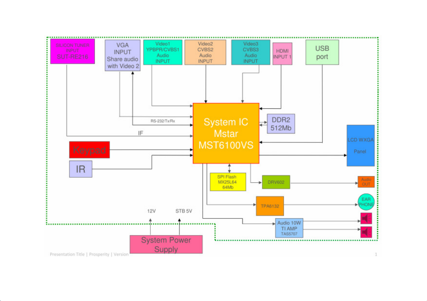
SPB42S 42” Block Diagram
17
Page 18
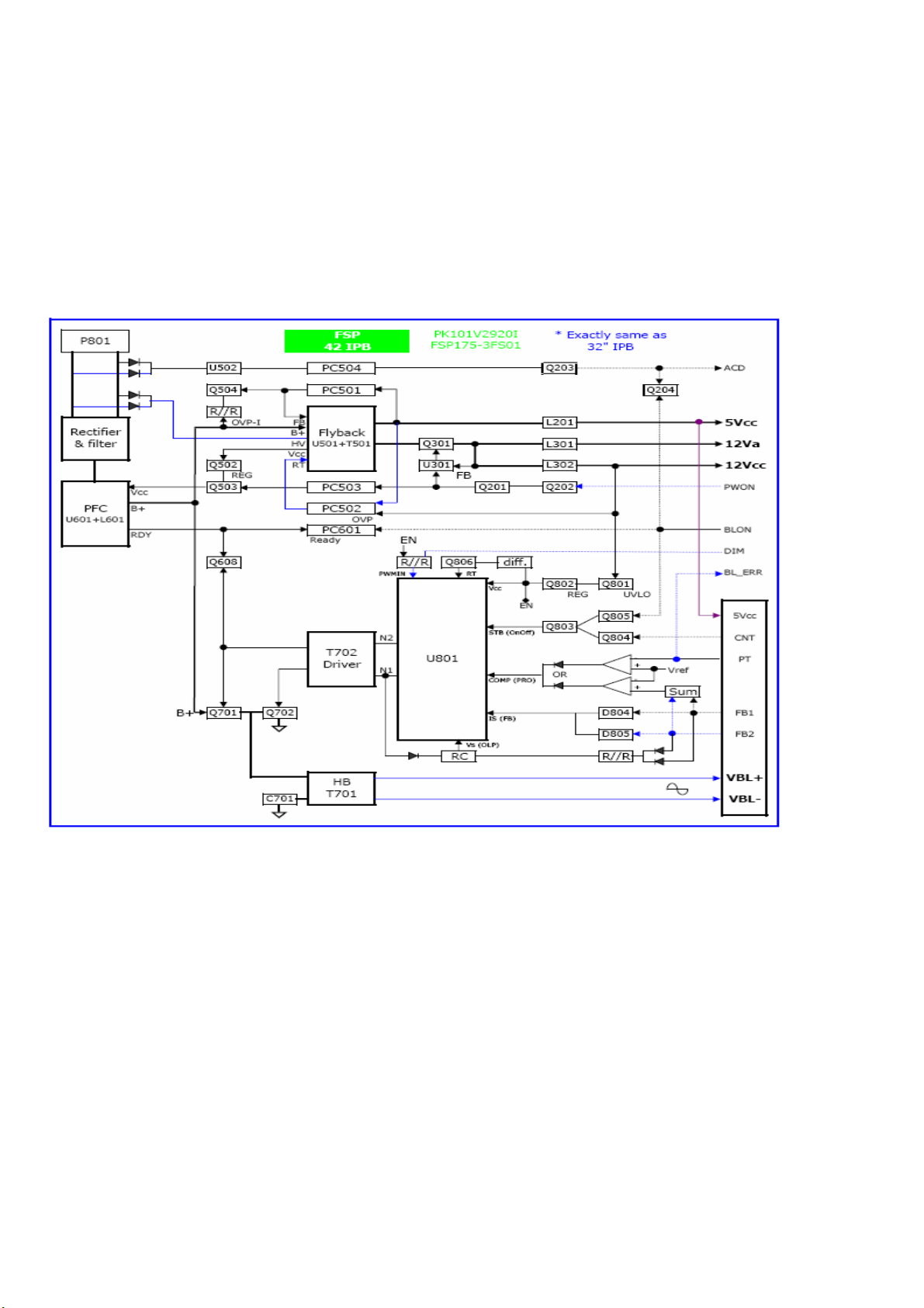
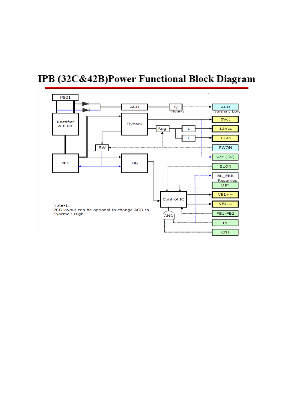
SPB42S Block Diagram
4-1 Power Block Diagram
SPB42S:
FSP power board:
18
Page 19
Page 20
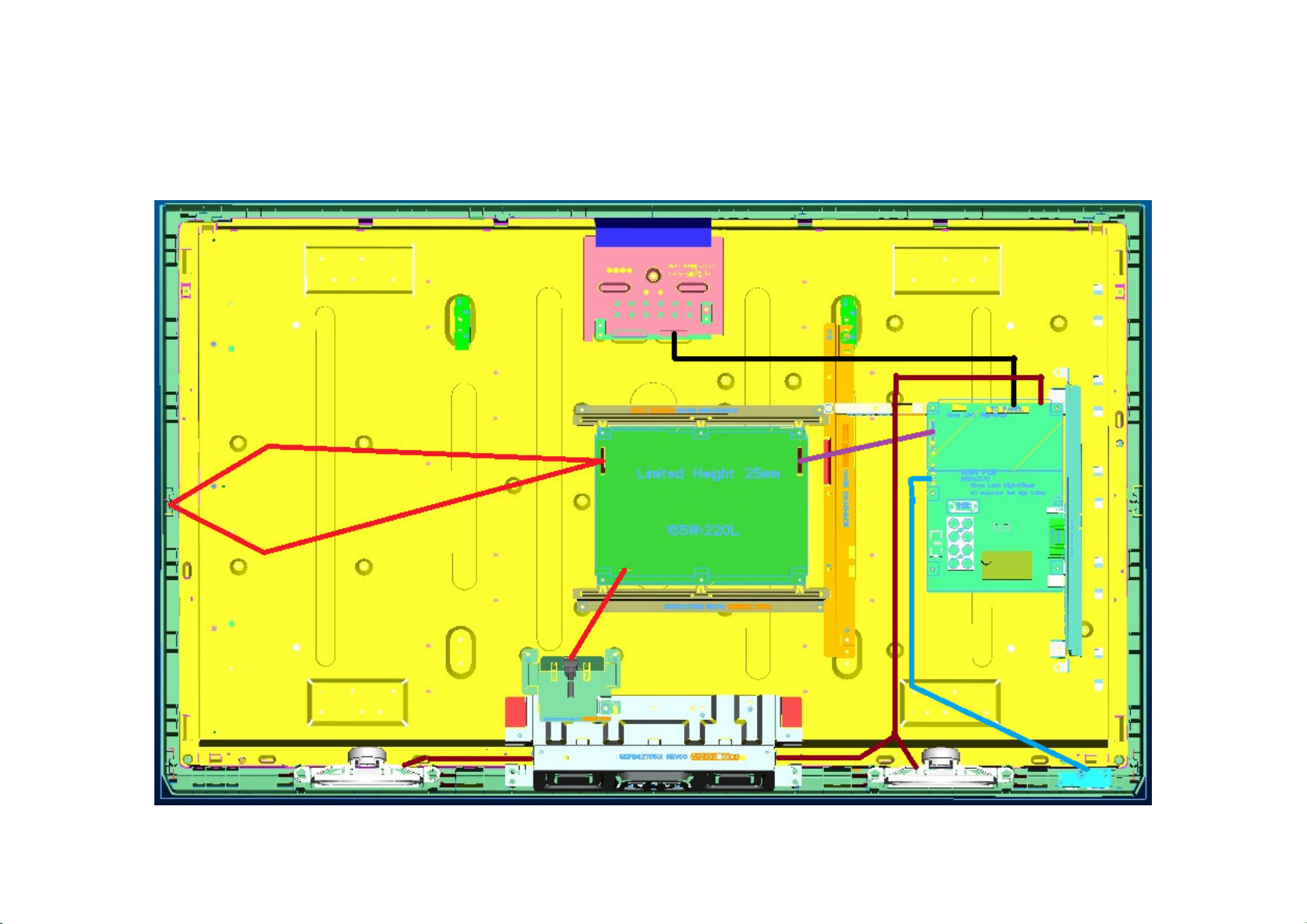
I. BLOCK
SPB42S 42-inch Wiring Diagram
33
Page 21
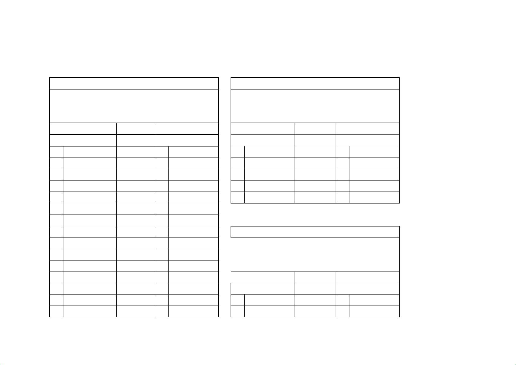
II. Wiring Connection
1
1
2
2
3
4
3
5
4
6
7
8
9
10
11
12
13
14
1
15
2
AUO panel
Main board to Panel
SPB42S
DC02L00270I
480 mm
Panel side Main board CN17
FI-RE51S-HF LVDS cable A2006WV0-2X40P
NC NC
NC NC
NC NC
NC NC
NC NC
NC NC
LVDS_SEL PURPLE 33 LVDS_SEL
NC NC
NC NC
NC NC
Main board to Speaker
SPB42S
DC02V03460I
L:580 & R:955 mm
Main board CN3 Speaker
JWT A2001WV2-4P Color Right
SPK_OUTR+ Red P5 Speaker -
SPK_OUTR- Black P4 Speaker +
SPK_OUTL- White P2 Speaker +
SPK_OUTL+ Green P3 Speaker -
Main board to IR board
SPB42S
DC02V03450I
Left
NC NC
CH1_0- WHITE 27 LVDS_D0O_N
CH1_0+ BLUE 28 LVDS_D0O_P
CH1_1- WHITE 25 LVDS_D1O_N
CH1_1+ ORANGE 26 LVDS_D1O_P
IR board CN1 Main board CN4
JWT A2001WR2-5P Color JWT A2001WR2-5P
LED_C Black 1 LED_C
LED_G Brown 2 LED_G
440 mm
34
Page 22
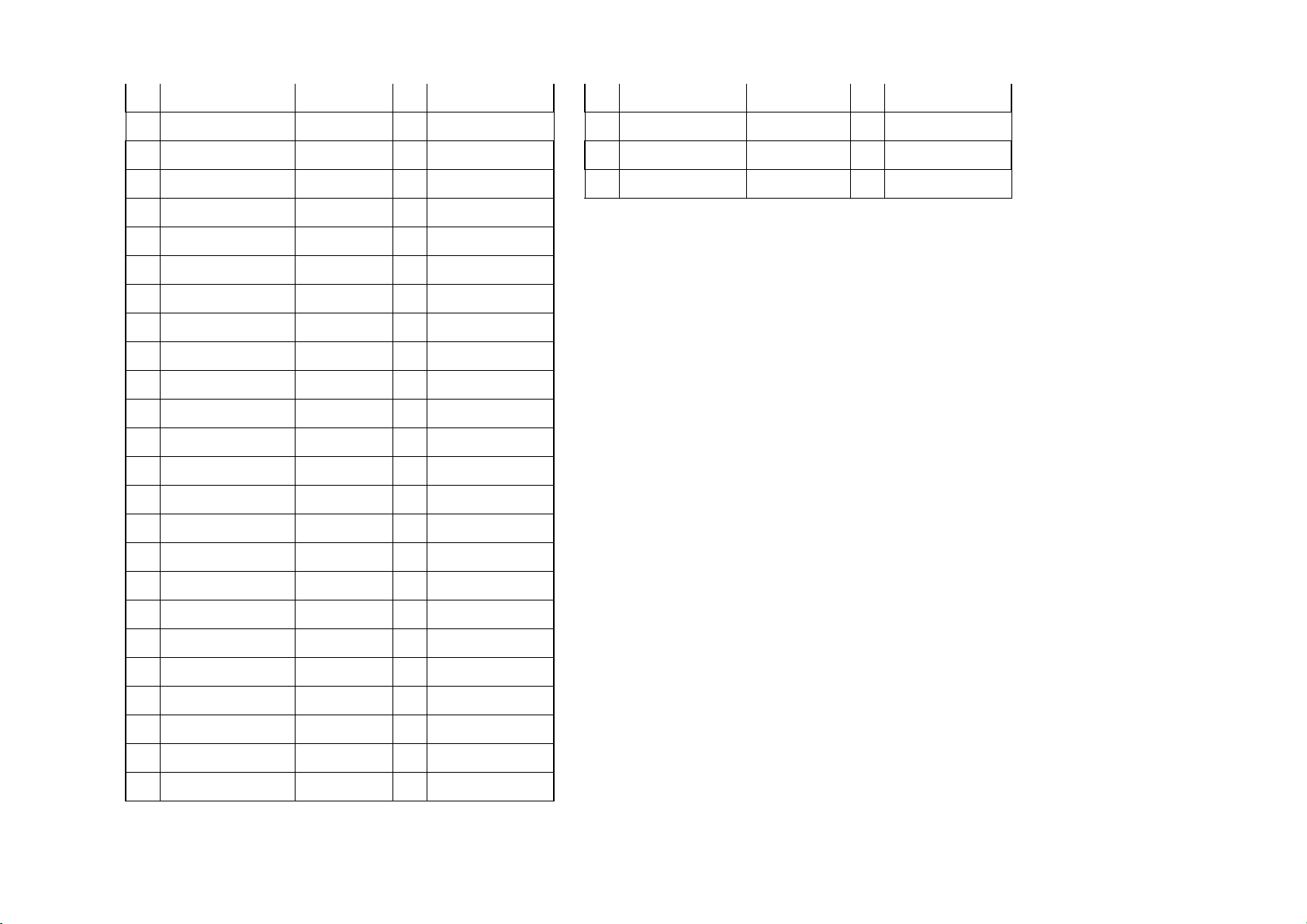
16
CH1_2- WHITE 23 LVDS_D2O_N
3
17
4
18
5
19
6
20
21
22
23
24
25
26
27
28
29
30
31
32
33
34
35
36
37
38
39
40
LED_R Red 3 LED_R
CH1_2+ GREEN 24 LVDS_D2O_P
GND BLACK 1 GND
CH1_CLK- WHITE 21 LVDS_CO_N
CH1_CLK+ YELLOW 22 LVDS_CO_P
GND BLACK 2 GND
CH1_3- WHITE 19 LVDS_D3O_N
CH1_3+ BROWN 20 LVDS_D3O_P
NC NC
NC NC
GND BLACK 3 GND
GND BLACK 4 GND
CH2_0- WHITE 15 LVDS_D0E_N
CH2_0+ BLUE 16 LVDS_D0E_P
CH2_1- WHITE 13 LVDS_D1E_N
CH2_1+ ORANGE 14 LVDS_D1E_P
CH2_2- WHITE 11 LVDS_D2E_N
GND Orange 4 GND
IRR Green 5 IRR
VCC5_0_STB Yellow 6 VCC5_0_STB
CH2_2+ GREEN 12 LVDS_D2E_P
GND BROWN 29 GND
CH2_CK- WHITE 9 LVDS_CE_N
CH2_CK+ YELLOW 10 LVDS_CE_P
GND BLACK 30 GND
CH2_3- WHITE 7 LVDS_D3E_N
CH2_3+ BROWN 8 LVDS_D3E_P
NC NC
35
Page 23
41
NC NC
42
43
44
45
46
47
48
49
50
51
GND BLACK 31
GND BLACK 32
GND BLACK 34
GND BLACK 35
GND BLACK 36
NC NC
Vdd RED 37 LVDS_PWR
Vdd RED 38 LVDS_PWR
Vdd RED 39 LVDS_PWR
Vdd RED 40 LVDS_PWR
36
Page 24
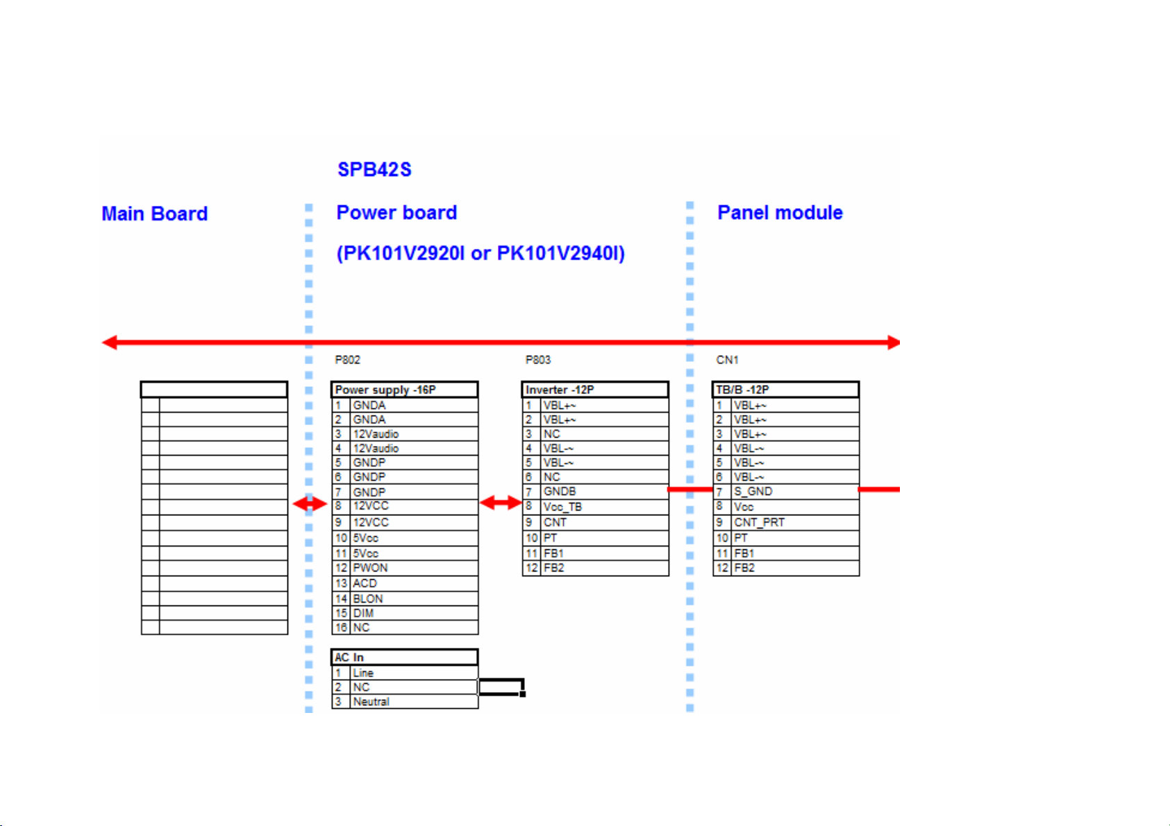
III.
Wiring Connection(POWER)
37
Page 25
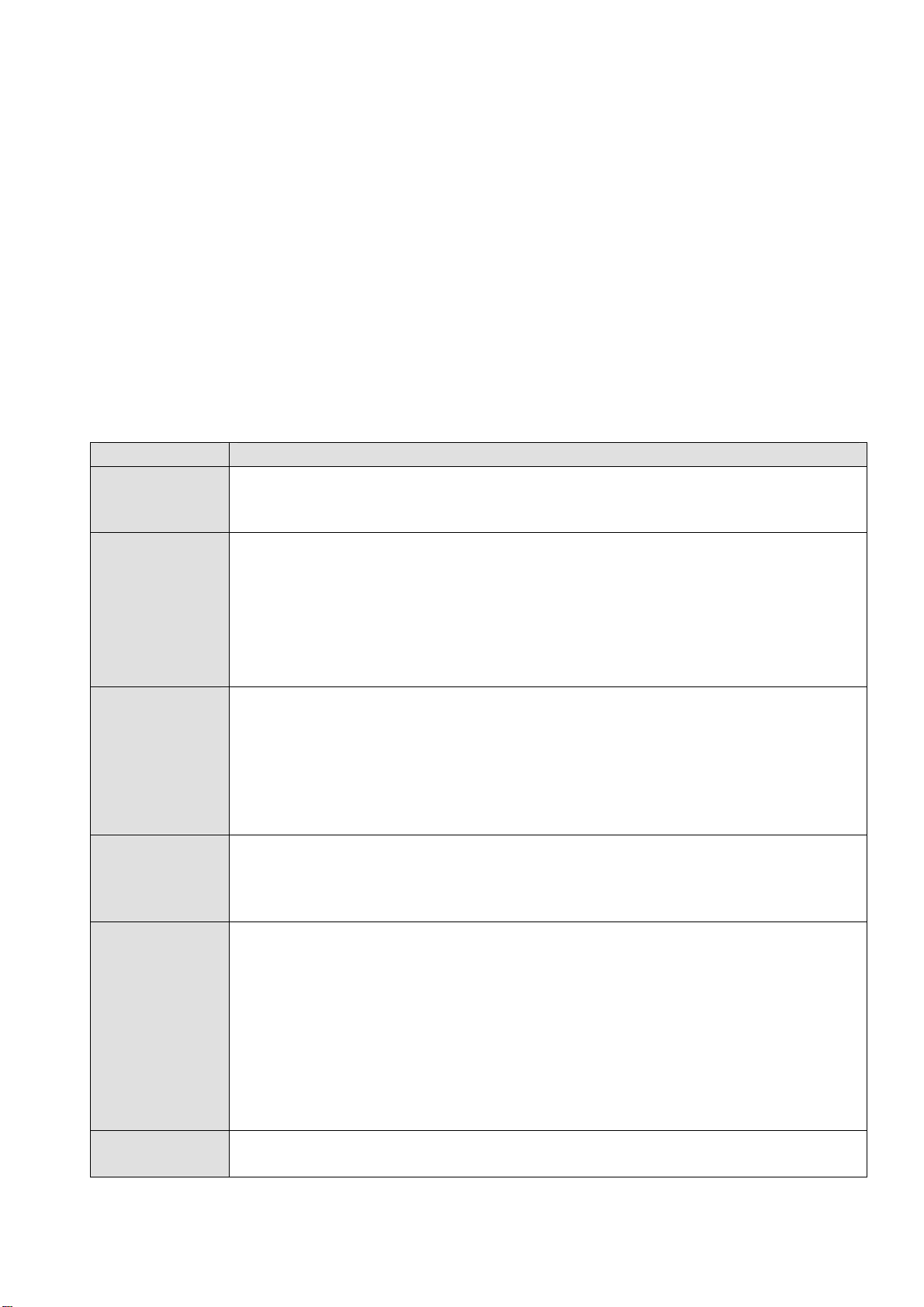
Trouble shooting
1. Fault clearance
Before calling your dealer or service center for assistance, check the matters below once again.
(1) Make sure you have connected LCD TV to your equipment as described in the section
“ CONNECTING LCD TV”.
(2) Check cable connection. Verify that all external equipment and power cord are properly
connected.
(3) Verify that all power is switched on.
(4) If LCD TV still dose not produce an image, re-start the external equipment.
(5) If the image still not appears, unplug LCD TV from the external equipment and check the external
equipment. The problem may be with your graphics controller rather than with LCD TV. (When
you reconnect LCD TV, remember to turn the external equipment and TV off before you power up
LCD TV. Power the equipment back on in order of LCD TV and external equipment.)
(6) If the problem still exists, check the following chart.
Problem Try these Solutions
NO POWER
Remote
Control dose
not work
No image
No sound
There are tiny
black points
and/or bright
point on the TV
Abnormal
color of image
Plug this LCD TV into the AC outlet.
Press POWER button on side control or on Remote Control to turn on LCD TV.
Check POWER Indicator. If this indicator blank, this TV has getting trouble.
Check the batteries.
Make sure nothing is between the Remote Receiver and the Remote Control.
Make sure you are not too far from LCD TV when using Remote Control.
Maximum operating range is 5m.
Is direct sunlight or strong artificial light shining on LCD TV‘s Infrared Remote
Receiver? Eliminate the light by closing curtains, pointing the light in a different
direction, etc.
Check the connection between the external equipment and LCD TV.
When turning LCD TV on, it takes a few seconds to display the image.
Check the system that you select is corresponding with the external equipment
or the video equipment.
Make sure the temperature is not out of the Operating Temperature (0°C ~
50°C).
Turn off power, then turn on again, re-start LCD TV.
Check Audio cable connection from Audio input source.
Adjust the Sound System.
Press VOLUME (+) button.
Press MUTE button.
Dark or bright points of light (red, green, or blue) may appear on the screen.
This is a characteristic of the LCD panel, not a malfunction of the LCD TV.
LCD panel is produced with very high accuracy technology. There is 99.99% or
more dot pixel, but there is also 0.01 % or less of dot pixel lack or dot pixel that
is constantly lighted. This is not defect.
Regarding LCD panel characteristic, it may occur picture remain (look like a
mirror) when the screen is changed if it displays same screen for a long time.
Changing the picture or turn-off the power supply may recover.
Stripe pattern (more, interference stripes) may show up on the screen depends
on the reflected picture.
Adjust the value of color.
Select different color system.
38
Page 26
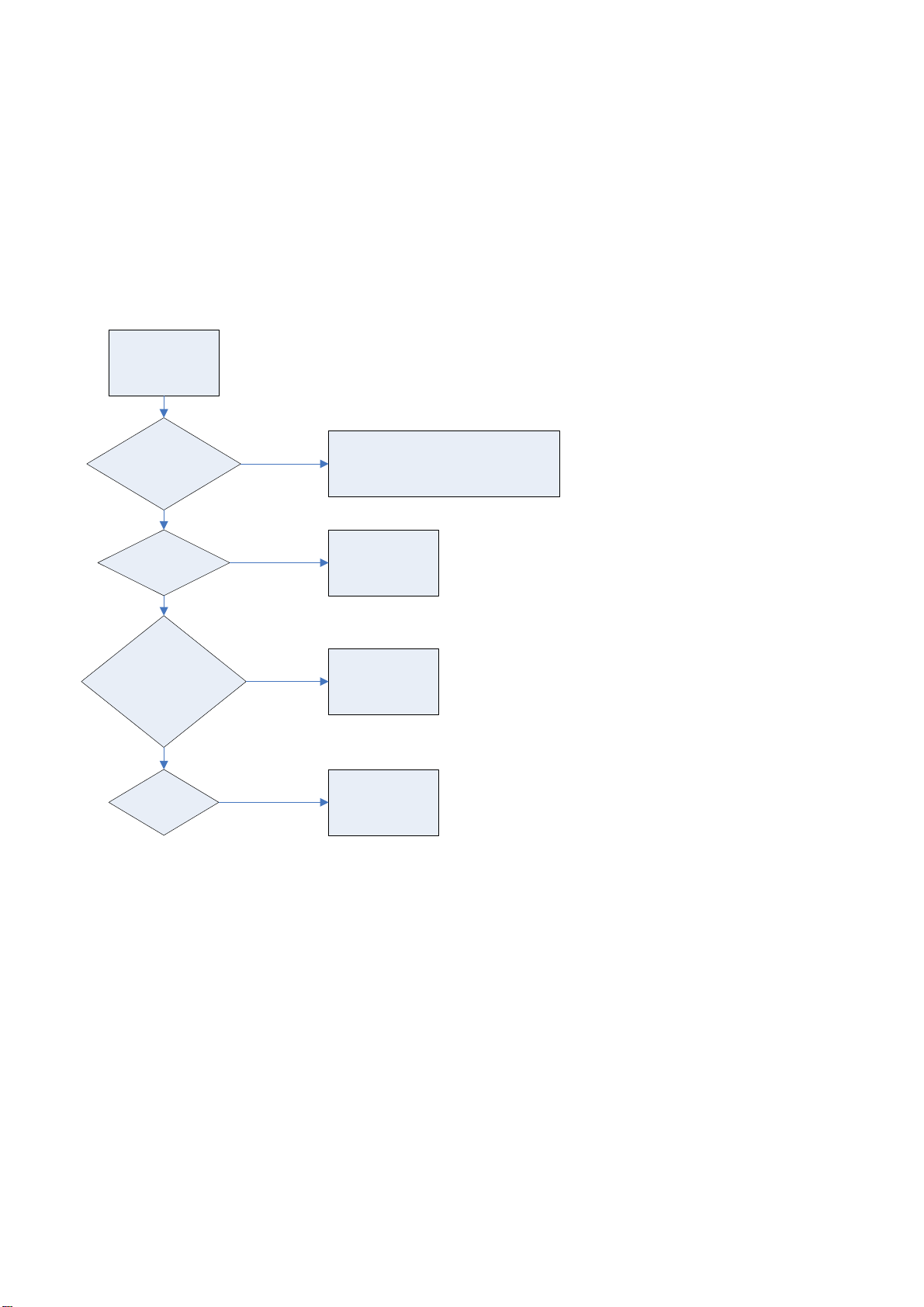
2. Troubleshooting guide
The flow chart shown below will help you to troubleshoot your Televison set with it doesn’t display
no
rmally. Each procedure offers a simple way to check for system errors. Before starting, ensure
that there is a signal in and that the Televison is turned on.
2-1 Power LED no light
Power LED no
i
ght
L
Check Pin 10/11 of
02 of Power Board
P8
OK
Check Pin 6 of CN4
OK
Stand-By mode
OK
eck
Ch
Pin 1: Low
Pin 2: High
Pin 3: Low
Check LED
NG
NG
N
NG
Change
wer Board
PN: PK101V2920I or PK101V2940I
Change M/Board
G
Change M/Board
Change LED Board
Po
39
Page 27
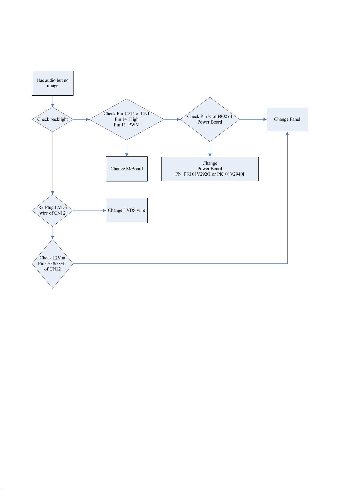
2-2 Has audio but no video out
40
Page 28
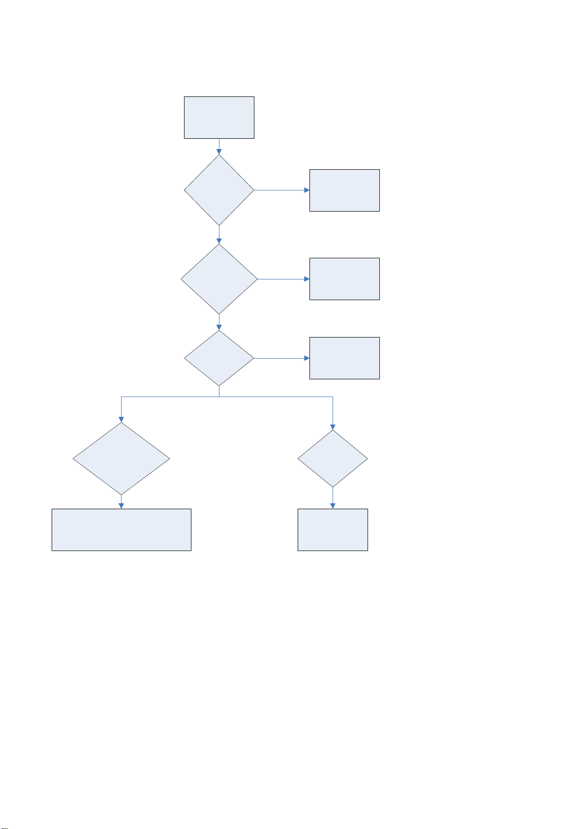
2-3 Has video but no audio out
Has image but no
so
und
Check 12V at Pin 3 / 4
P802 of Power Board
of
Make sure the
u
te function is
M
Off
Make sure the
n
put source works
i
normally
Speaker wire
nnects stoutly
co
Un-Mute by
e
mote Controller
R
Change source
Re-connect the wire
Check 12V at
n 3 /4 of CN1
Pi
Change
wer Board
PN: PK101V2920I or PK101V2940I
Po
Change M/Board
41
Page 29
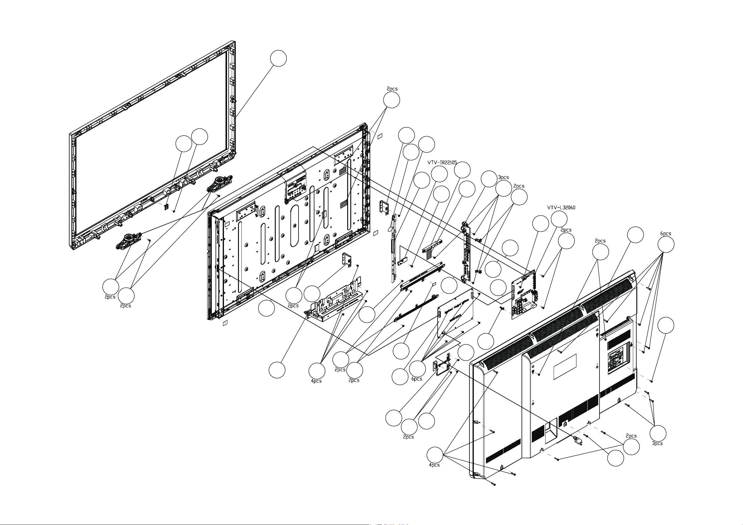
APPENDIX-B: SPB42 Exploded View
1
37
3
12
30
11
6
33
28
38
28
35
25
38
16
11
7
27
37
20
4
41
5
8
31
39
15
11
2
11
38
40
9
38
26
41
29
34
17
41
39
38
11
36
10
11
13
38
Page 30
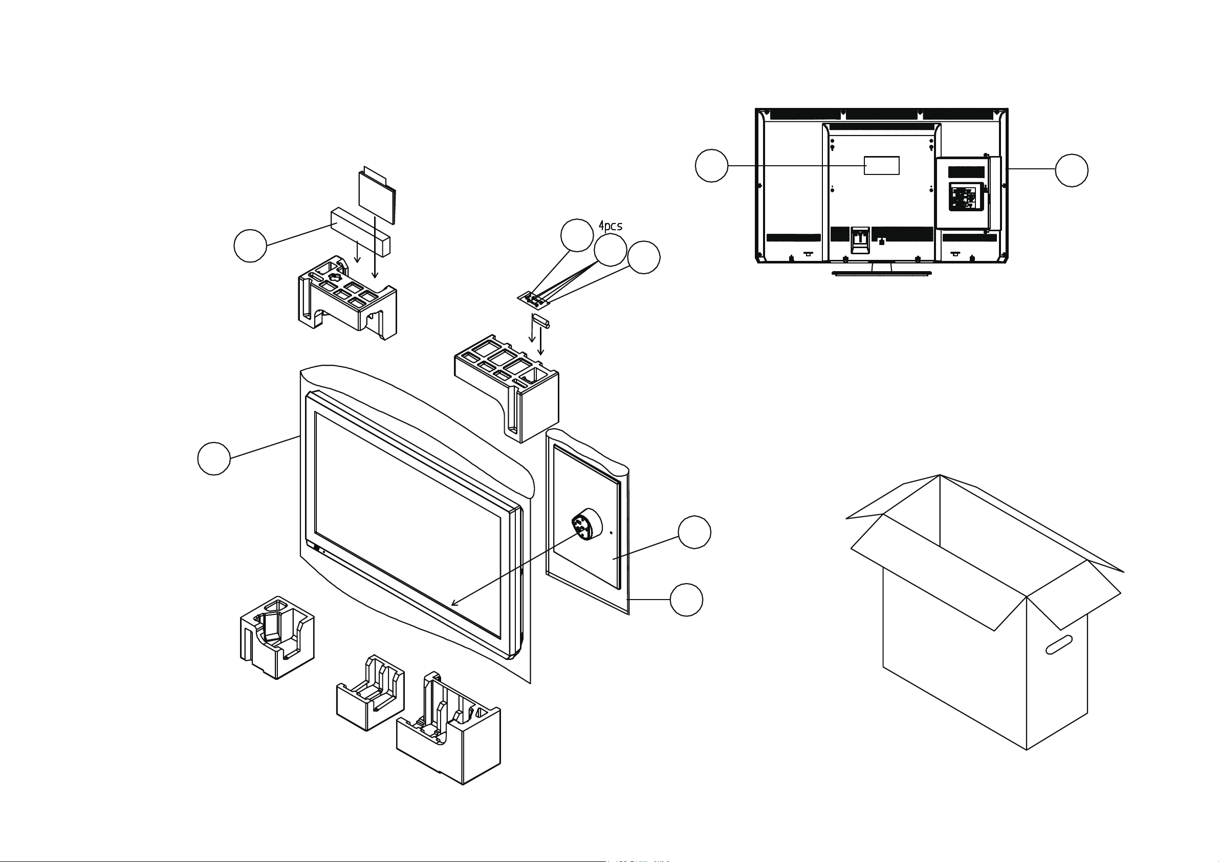
APPENDIX-B: SPC42 Exploded View
14
42
24
23
22
32
21
18
19
Page 31
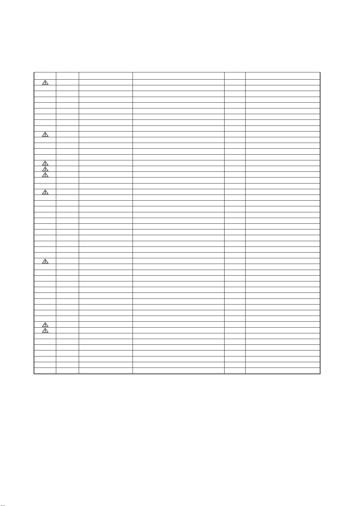
9. Replacement Parts List
Safety Ref.No. Part No. Part Name & Description Pcs Remarks
1 TZZ00000151A BEZEL ASY(ASIA-5*/5 1
2 TZZ00000152A BACK COVER ASY(ASIA) 1
3 TZZ00000030A SPK SET(90d)(PIN12d) 2
4 TZZ00000612A H-CON SET 1
5 TZZ00000035A H-CON SET 1
6 TZZ00000036A H-CON SET 1
7 TZZ00000615A H-CON SET 1
8 TZZ00000616A H-CON SET 1
9 TZZ00000042A BOTTOM BRKT 1
10 TZZ00000633A PWR CORD(S) 1
11 TZZ00000086A SCREW 17
12 TZZ00000087A SCREW+WASHER 2
13 TZZ00000090A TAPPING SCREW 2
14 TZZ00000073A PE BAG-TV 1
15 TZZ00000601A FIRMWARE M/B 1
16 TZZ00000598A PCBA IR/B 1
17 TZZ00000111A PWR MODU(SPB42PTA) 1
18 TZZ00000096A STAND ASY 1
19 TZZ00000072A PE BAG-STAND 1
20 TZZ00000605A KEY PLATE ASY(ASIA) 1
21 TZZ00000138A KEY LABEL-32C5D/42U5 1
22 TZZ00000071A ZIPPERED BAG 1
23 TZZ00000654A SCREW+2WASHER 4
24 TZZ00000659A TAPPING SCREW 1
25 TZZ00000041A PANEL BRKT (R) 1
26 TZZ00000097A POWER PCB BRKT 2
27 TZZ00000098A MAIN PCB BRKT 1
28 TZZ00000099A WALL MOUNT BRKT 2
29 TZZ00000043A POWER CABLE SR BRKT 1
30 TZZ00000100A PANEL SUPPORT BM 1
31 TZZ00000051A PCB SPRING 2
32 TZZ00000625A RATING LABEL-42U5D 1
33 TZZ00000102A SPONGE 2
34 TZZ00000159A CR-4305 FOAM+F247 1
35 TZZ00000078A LOCKING CABLE TIE 1
36 TZZ00000109A PST-12 (GIN LIAN) 1
37 TZZ00000079A MYLAR AL TAPE 3
38 TZZ00000082A SCREW 10
39 TZZ00000083A SCREW+LOCK WASHER(8) 7
40 TZZ00000089A TAPPING SCREW 1
41 TZZ00000110A SCREW(NL) 7
42 TZZ00000139A REMO CTRL AAA 1
N/A LCD MODU 1
N/A OWNER'S MANUAL 1
N/A EPS FOAM (T-L) 1
N/A EPS FOAM (T-R) 1
N/A EPS FOAM (B-L) 1
N/A EPS FOAM (B-R) 1
N/A EPS FOAM (B-M) 1
N/A CARTON-TH-L42U5D 1
31
Page 32
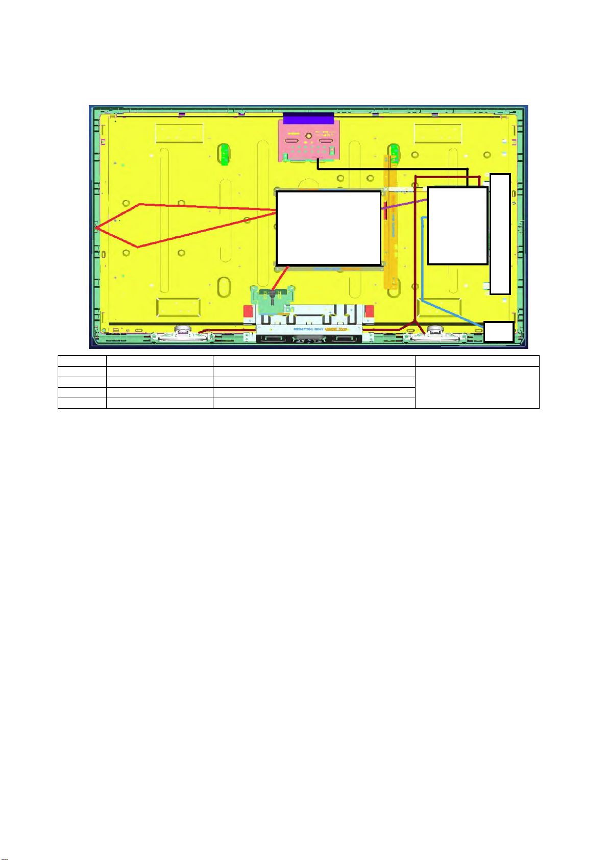
10. Boards Layout
17
Ref No. Board Name Function Remrks
16 PCBA IR/B Remote Receiver, LED
15 FIRMWARE M/B Main Board, Audio & Video Signal Processing
17 PWR MODU Power (AD/DC), DC-DC
20 KEY PLATE ASSY Control Button
All boards are non servicable
and should be exchanged for
service
15
20
16
32
Page 33
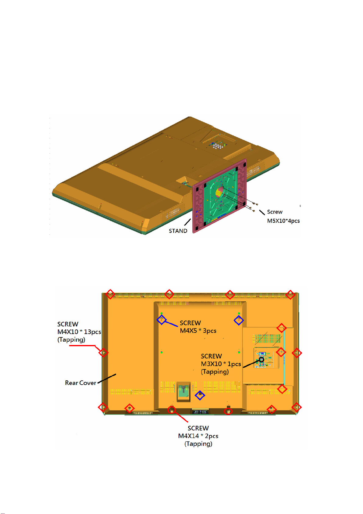
11 Disassembly and Assembly Instructions
11.1. Stand
1. Lay down the unit so that the rear cover faces upward.
2. Remove the 4 screws.
3. Remove the stand
11.2. Rear cover
1. Remove the total 19 screws.
2.
Remove the rear cover.
Page 34
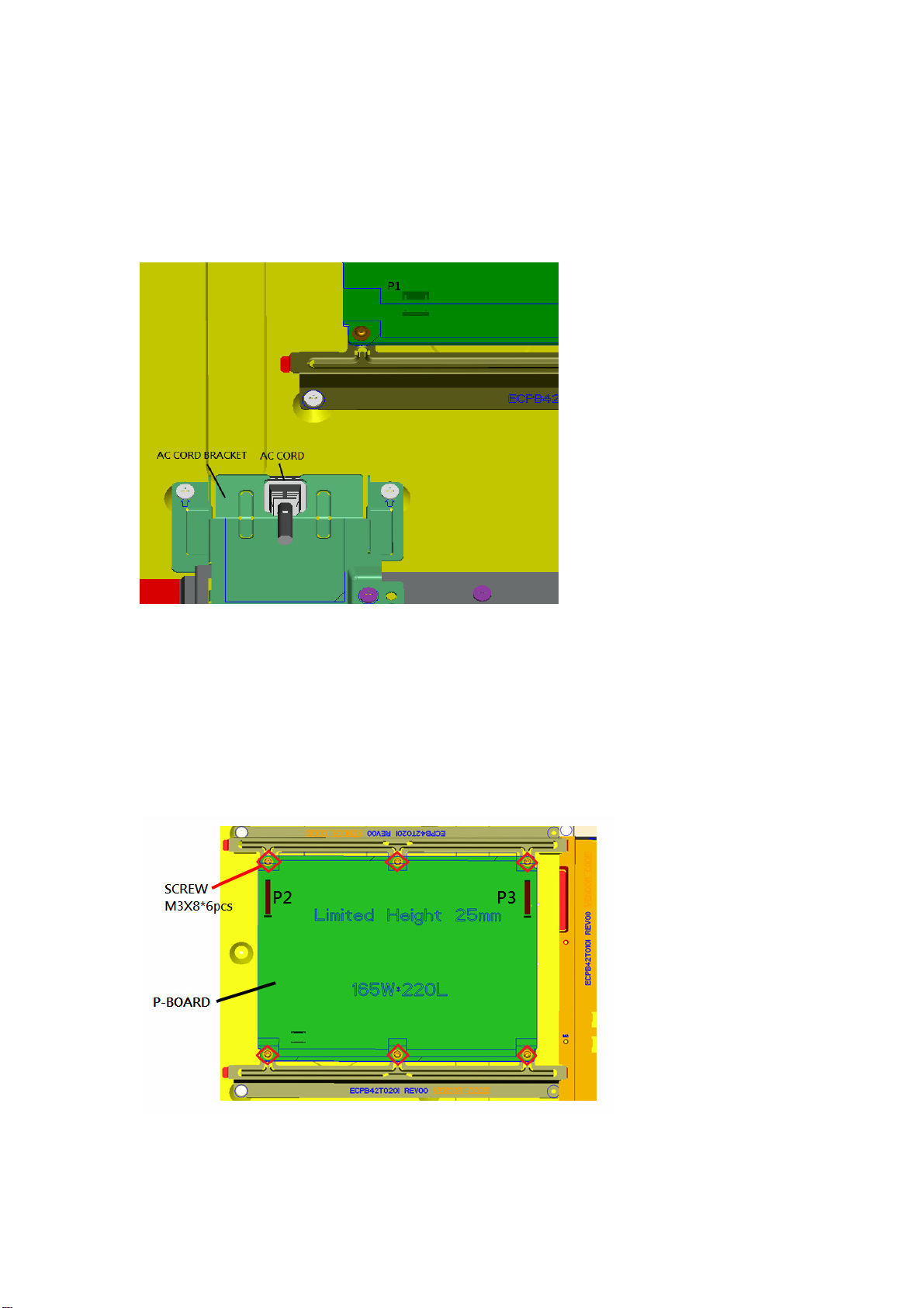
11.3. Remove AC cord
1. Remove the bushing of the AC cord from the AC cord bracket.
2. Disconnect the connector (P1) of AC cord.
11.4. P-Board
1. Remove the 6 screws.
2.
Disconnect the connectors (P2, P3).
3. Remove the P-Board.
Page 35
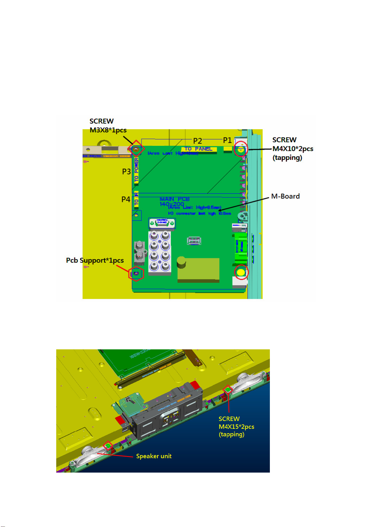
11.5. M-Board
1. Remove the 3 screws.
2. Disconnect the connectors (P1, P2, P3, P4).
3. Remove the M-Board.
4. Remove the PCB-support.
11.6. Speaker unit
1. Remove the 2 screws.
2.
Remove the speaker units.
Page 36
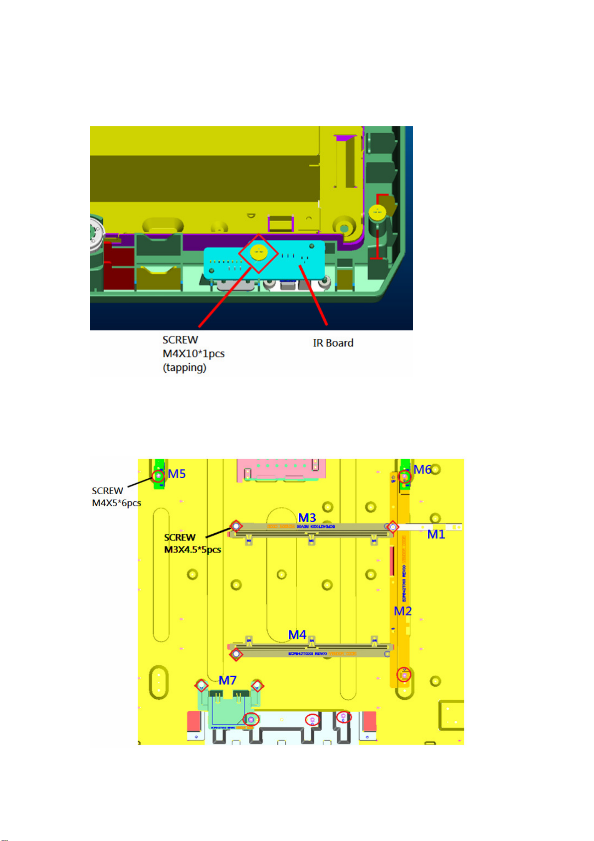
11.7. IR-Board
1. Remove the 1 screw.
2. Remove the IR-Board.
11.8. Metal parts I
1. Remove the 11 screws.
2.
Remove the metal parts (m1,m2, m3,m4,m5,m6,m7).
Page 37
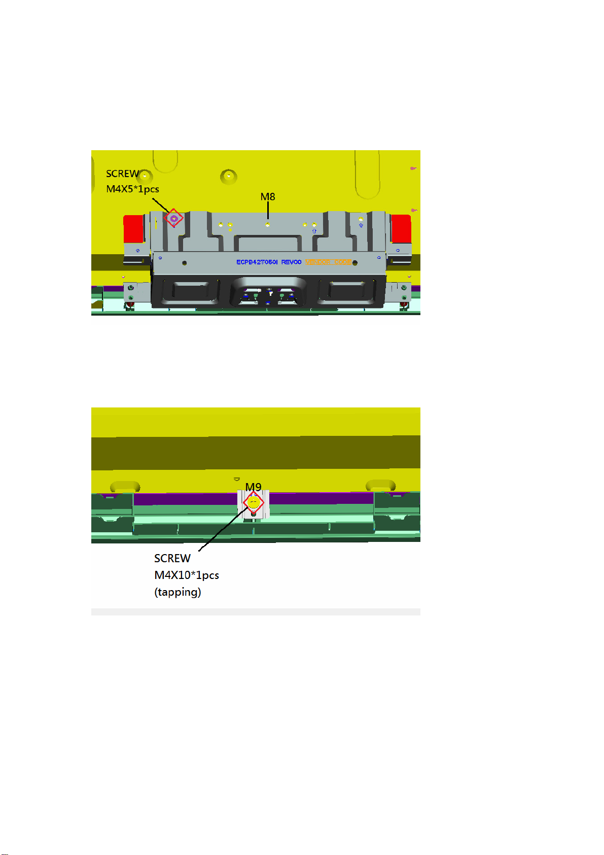
11.9. Metal parts II
1. Remove the 1 screw.
2. Remove the metal part (m8).
11.10. Metal parts III
1. Remove the 1 screw.
2. Remove the metal part (m9).
Page 38
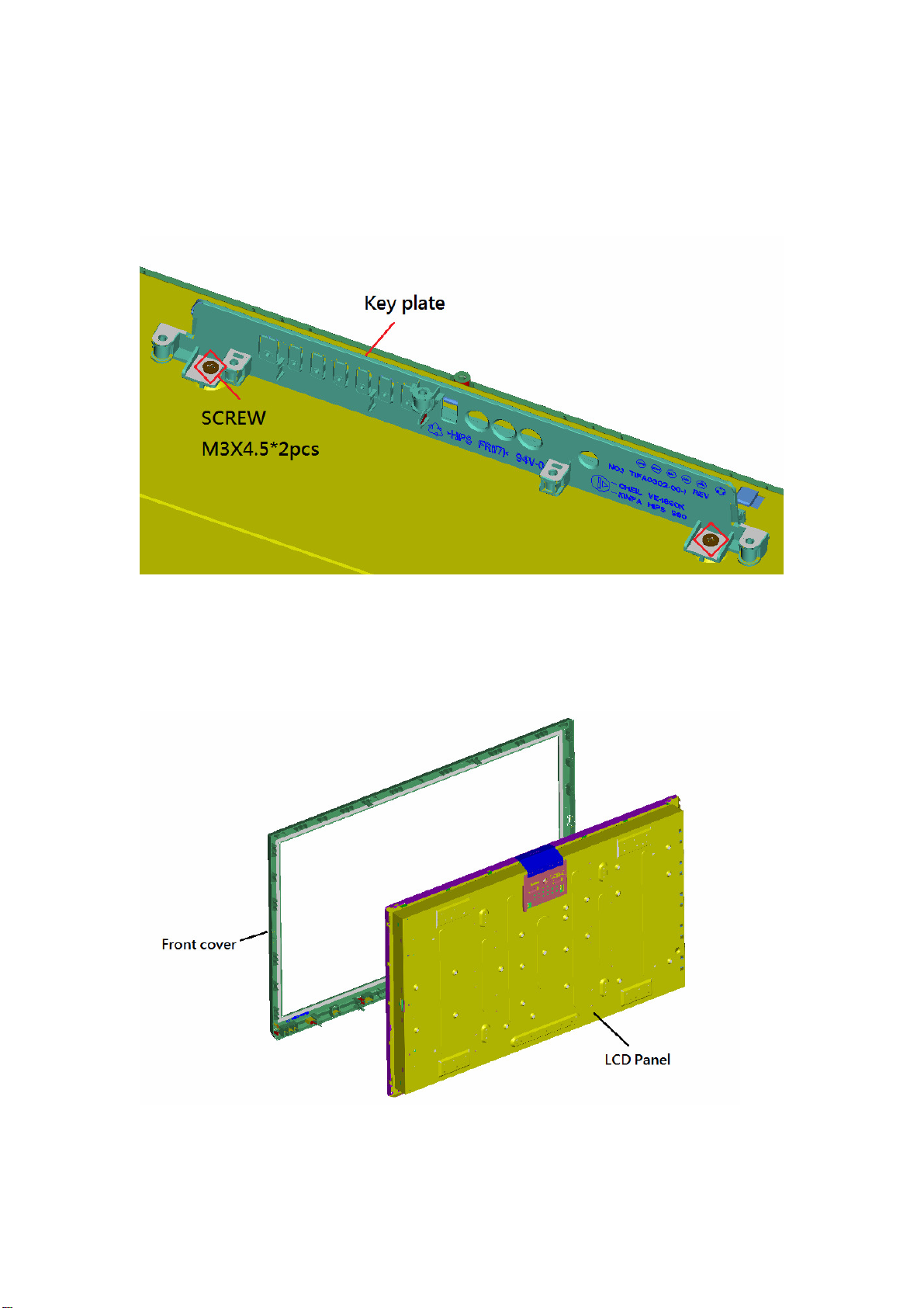
11.11. Key plate
1. Remove the 2 screws.
2. Remove the key plate.
11.12. LCD Panel
1. Remove the LCD panel.
 Loading...