

Page 1
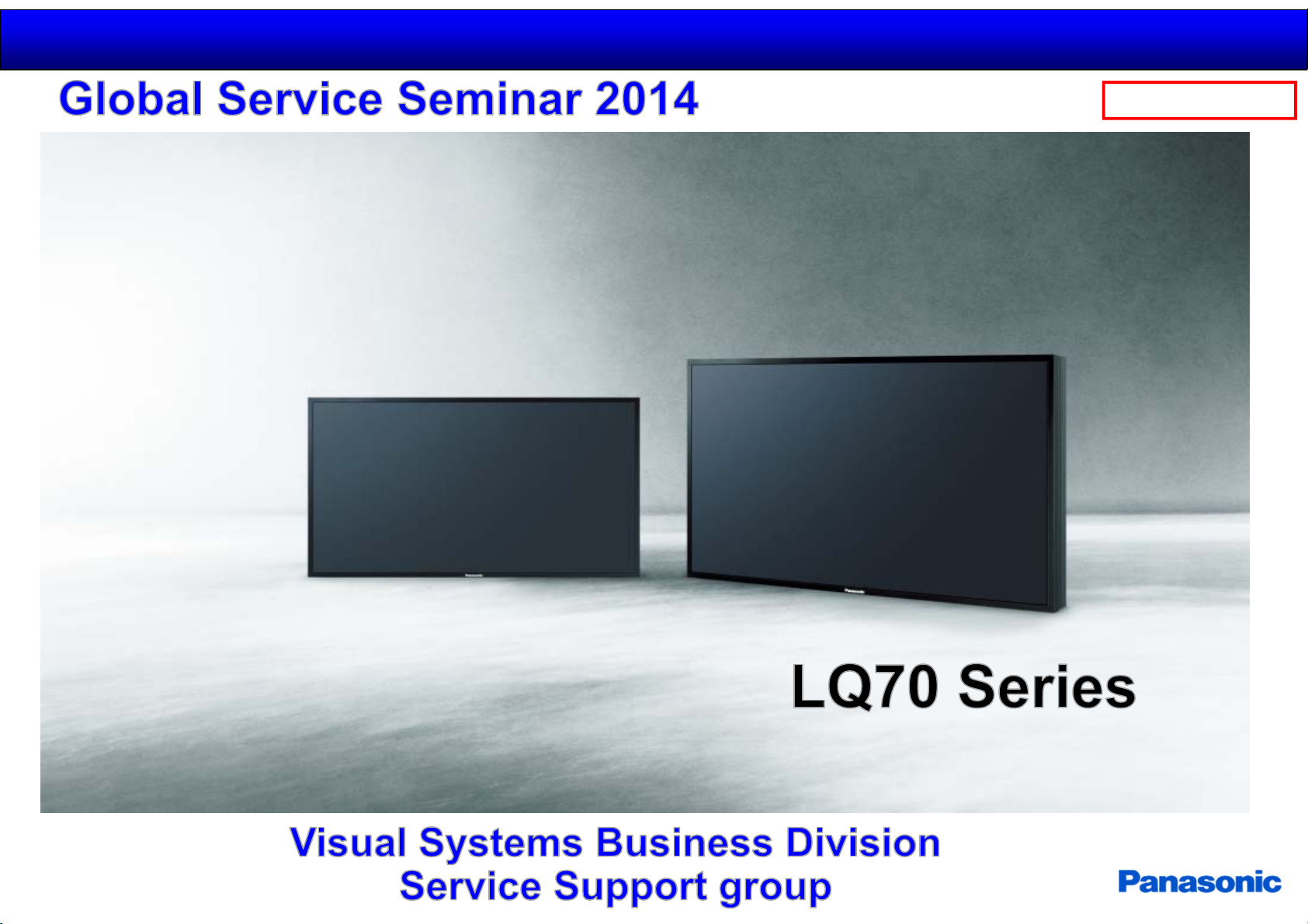
Durable and Professional
4K UHD LCD Displays
98”
84”
2014.11.12
1/44
Panasonic Internal
31”
TH-98LQ70TH-84LQ70
Page 2
Generalserviceinformation
2014.11.12
2/44
Panasonic Internal
GeneralInformationof4K
MainFeature
BlockDiagrams
Structure/Disassemble
ServiceInformation
Adjustment/Upgrade
Page 3
General service information
2014.11.12
3/44
◆ Responsibility
Function Responsibility
Design/Production VSBD (Japan)
Parts SSPG (Japan)
◆ Service information on spare parts ( All spare parts are supplied from AVC, Japan )
Spare Parts Parts Supply Service method Parts supply period
1 LCD Panel Yes
2PCB Yes
Component parts
3
for PCB
No PCB replacement -
On-site repair
by panel replacement
On site repair
by PCB replacement
LCD Panel shall be supplied for 7 years
after discontinuation of finished goods production.
PCB shall be supplied 7 years after final
production of the set.
Panasonic Internal
◆ Basic Policy
On-site replacement of faulty LCD Panel and PCB
- To realize quick repair, on-site replacement shall be applied.
Printed Circuit Boards (PCB)
- All PCB is unrepairable and shall be replaced by new PCBs.
- The components on PCB are NOT supplied as spare parts.
- All PCB shall be supplied for 7 years after final production of the set because all PCB is not repairable.
Jig
1) Crane
2) Service stand
3) Jack
4) Rope or Wire is necessary for service.
Page 4
Generalserviceinformation
2014.11.12
4/44
Panasonic Internal
GeneralInformationof4K
MainFeature
BlockDiagrams
Structure/Disassemble
ServiceInformation
Adjustment/Upgrade
Page 5
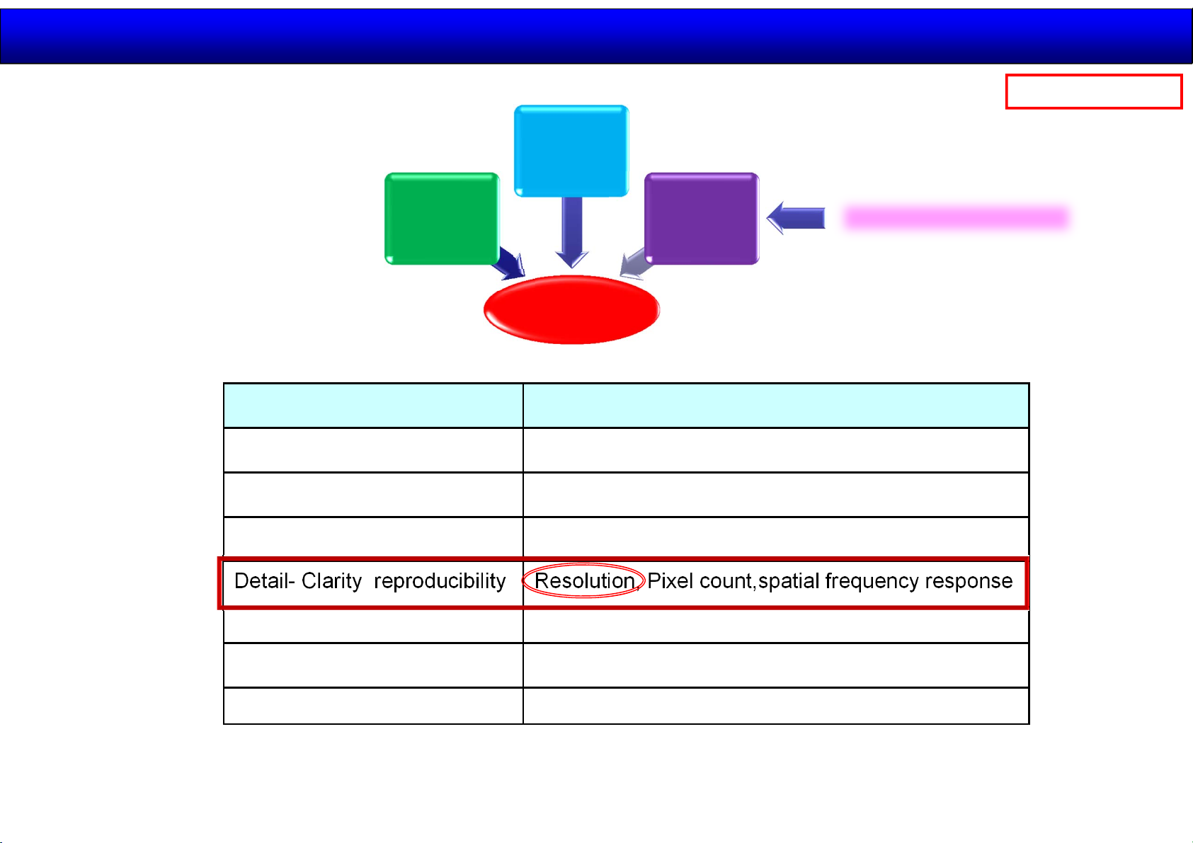
What for 4K?
2014.11.12
5/44
Panasonic Internal
Depth
< Picture Quality >
Dynamic range of brightness
Gradation reproducibility Gamut, bits count
Color reproducibility Gamut, color temperature
Detail- Clarity reproducibility Resolution, Pixel count,spatial frequency response
Large
Size
High
Picture
Quality
Live
feeling
Related Item
Brightness, contrast, sensitivity
4K Resolution
Moving image reproducibility Frame frequency, judder
Image obstruction Flicker, noise
Others Uniformity
Generally speaking, when the resolution exceed a certain level
“ Image on the screen “ ⇒ “ Reality “
Page 6
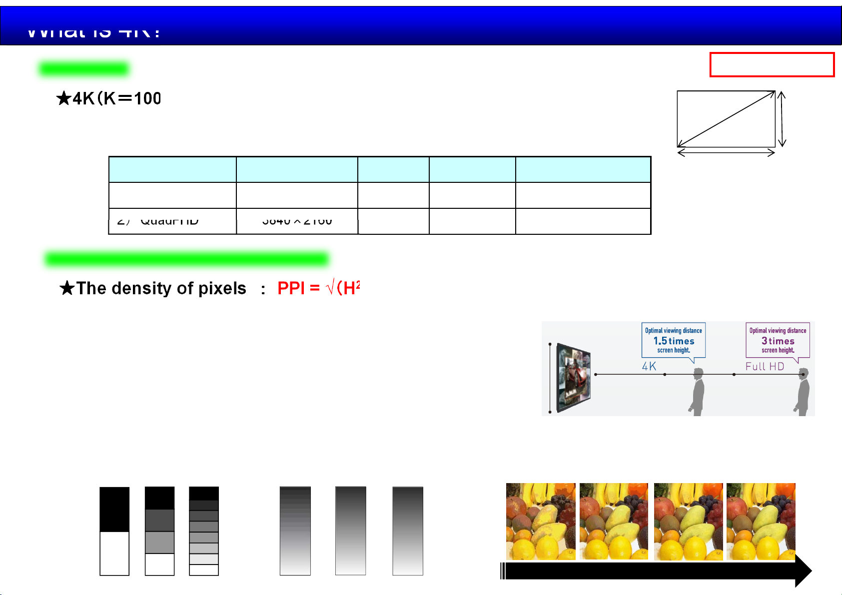
What is 4K?
2014.11.12
6/44
Definition
★4K(K=1000) means the number of the horizontal pixels.
⇒ Four times the resolution of Full-HD
★2 kinds of 4K standard.
Standard Resolution Aspect Pixel Remark
1) Full 4K 4096×2160 17:9
2) QuadFHD 3840×2160
( 2K:2048x1080 FHD:1920x1080 )
8,847,360
16:9 8,294,400
Visual influences human eyes
★The density of pixels : PPI = √(H
In general, it is said that the resolution of human eyes is approximately 90 ppi at 1m distance.
・4K Monitor (TH-98LQ70) 45
Panel Pitch 0.5622 x 0.5622mm
2
+V2)÷ D
ppi (1288x1.5≒2m )
Panasonic Internal
D
V
H
Cinema, Camera
Broadcast, TV
・FHD Monitor (TH-103PF12) 21 ppi (1419x3.0≒4m )
★Color
In general, it is said that the human eyes have ability to distinguish approximately 10 million colors.
⇒ 10bit LCD 2
1bit 2bit 3bit
30
= 1,073,741,824 >> 10,000,000
8bit 10bit
12bit
8bit 10bit6bit4bit
・・・
More gradation will become more smoothly
Page 7
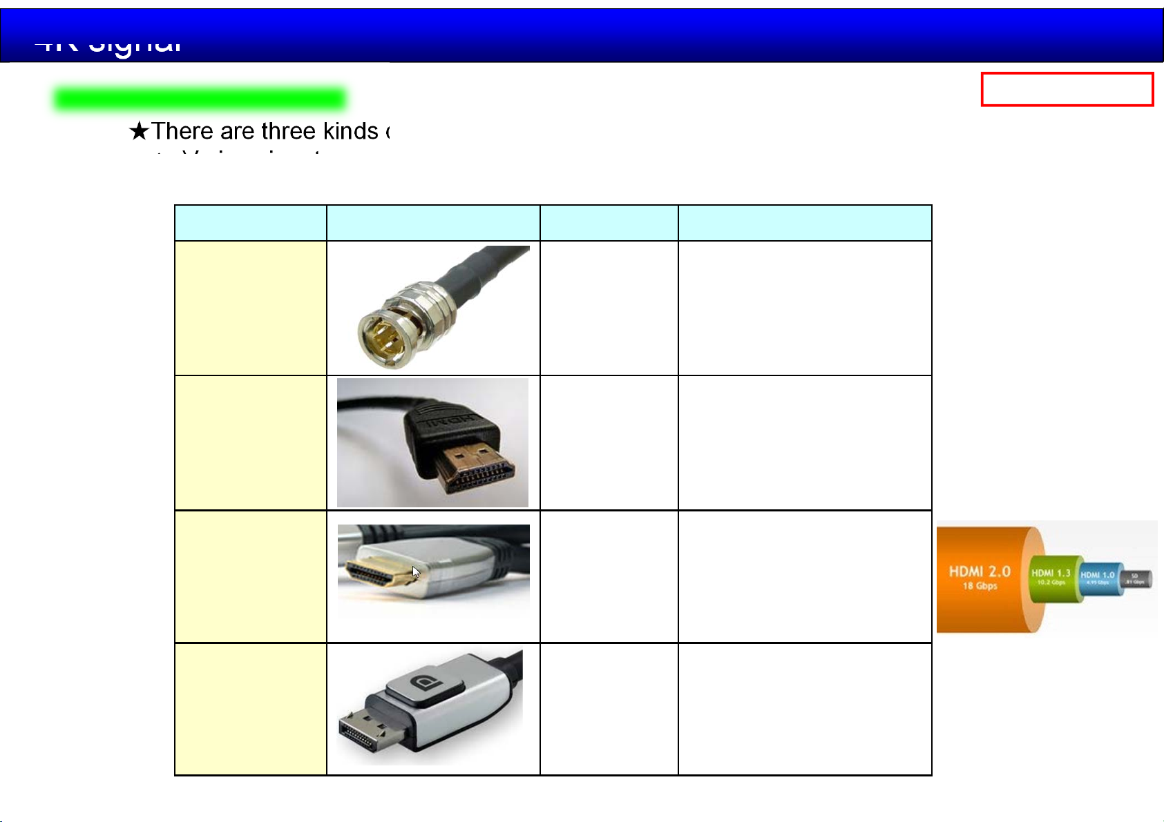
4K signal
Input / Transmission
★There are three kinds of input mainly. 3G-SDI / HDMI / Display Port
⇒ Various inputs are required by customer to connect various equipments.
★High bit rate is required. (4 times the data size of Full-HD)
Input Cable Bit rate Max Remark
2014.11.12
7/44
Panasonic Internal
3G-SDI 2.97 Gbps
HDMI 1.4b 10.2 Gbps
HDMI 2.0 18.0 Gbps
Broadcast, Camera,
Switcher, server
TV, Monitor, PC, server
(Audio 8ch)
8 bit 4:2:0 (4K 60p)
TV, Monitor, PC, server
(Audio 32ch)
12bit 4:2:0 or
8bit 4:4:4 (4K 60P)
DisplayPort
(1.2)
21.6 Gbps TV, Monitor, PC, server
Page 8
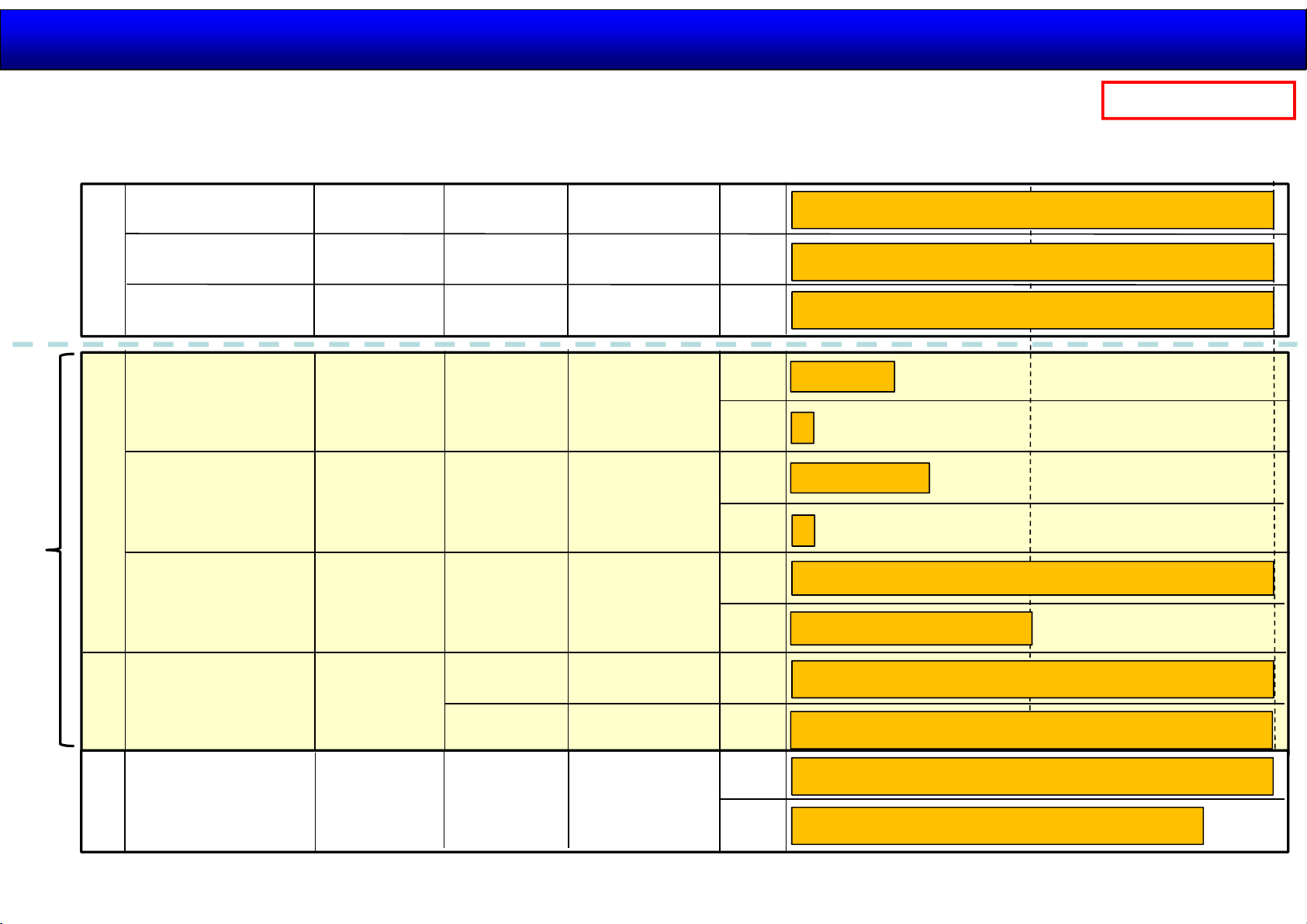
4K signal
2014.11.12
8/44
Panasonic Internal
LQ70 Series
Interface
TY-FB9HD
HD-SDI
TY-FB10HD
HD-SDI w/ audio
TY-FB11DHD
SLOT 2.0
Dual Link SDI
DP1.2 w/ audio
x1
HDMI2.0 w/ audio
x2
Standard
Digital Link *HDBase-T
x 1 (LAN port)
Max. support
format
~ FHD/60i
~ FHD/60i
~ FHD/60p
~ 4K/60p
~ 4K/60p 1
~ 4K/60p
(420, 8bit)
# of terminal
required
1
1
2
1
1
Max. data rate
1.5Gbps
1.5Gbps
3.0Gbps
FHD
FHD
FHD
FHD
21.6Gbps
FHD
18Gbps
FHD
10Gbps
4K
4K
4K
15 ~ 20m
few meter
15 ~ 30m
few meter
50m (CAT-5e)
Transmission distance
50m
100m
100m
100m
100m
70m (exclusive DM 8G cable)
100m
(Future)
SLOT NX
TY-TBN03G
3G-SDI w/ audio
x2
SLOT NX
TY-TBN12G
12G-SDI w/ audio
~ 4K/60p
~ 4K/60p
1
2/4
1
3Gbps
6 / 12Gbps
12Gbps
FHD
4K
FHD
4K
100m
100m
100m
80m
Page 9
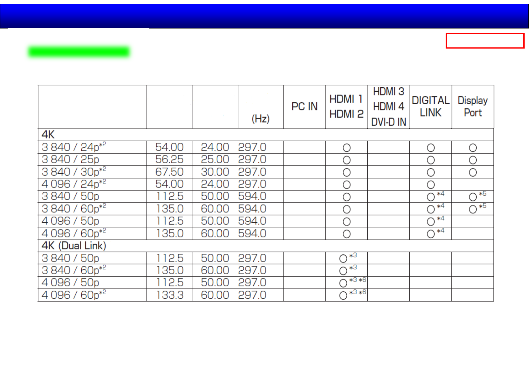
4K signal
Signal (TH-98LQ70)
2014.11.12
9/44
Panasonic Internal
< Operational manual >
Signal name
Horizontal
Frequency
(kHz)
Vertical
Frequency
(Hz)
Dot
clock
HDMI 2.0 HDMI 1.3
DP 1.2
*2: Also support 1/1.001 frequency
*3: Dual link support format
*4: YCbCr 4:2:0 support format
*5: Only support MST(Multi Stream Transport)
*6: Not indicating EDID
Page 10
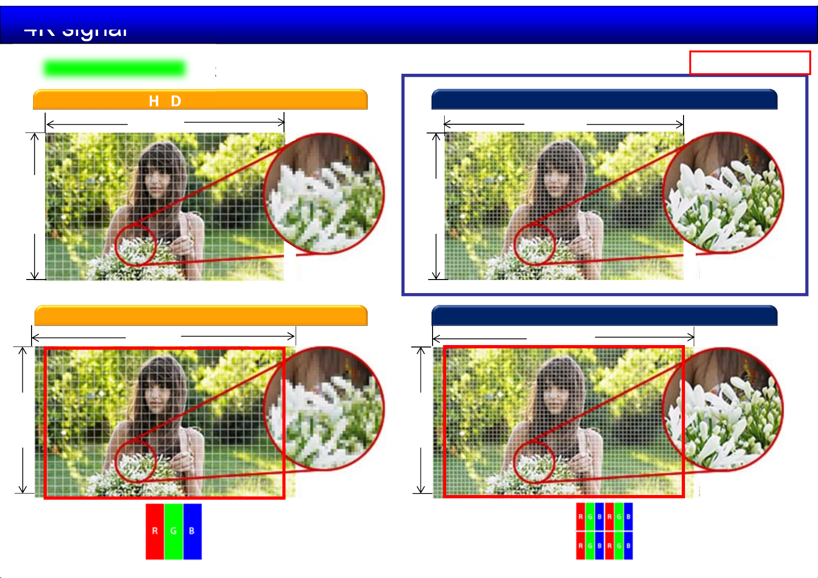
4K signal
2014.11.12
10 /44
Display image
1,920
1,080
2,048
Panasonic Internal
3840x2160 panel
HDInput Signal 1920x1080
3,840
2,160
2,073,600
2KInput Signal 2048x1080 Full4K Input Signal 4096x2160
QFHD Input Signal 3840x2160
8,294,400
4,096
1,080
2,211,840
2,160
8,847,360
LR70series Panel Pitch
98” 0.5622 x 0.5622mm
84” 0.4845 x 0.4845mm
Page 11
Generalserviceinformation
2014.11.12
11 /44
Panasonic Internal
GeneralInformationof4K
MainFeature
BlockDiagrams
Structure/Disassemble
ServiceInformation
Adjustment/Upgrade
Page 12
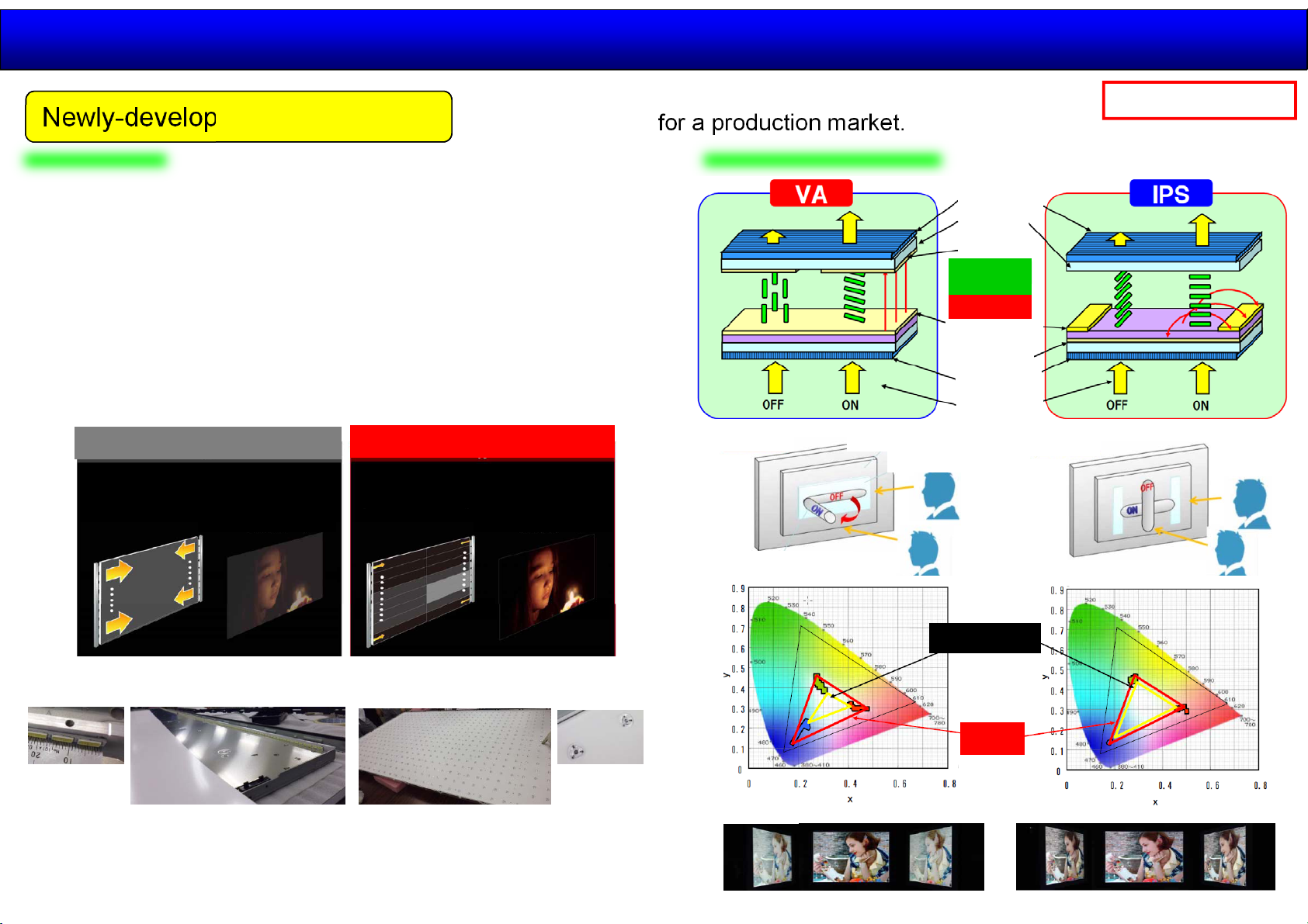
Feature High Picture Quality
Newly-developed 4K LCD Panel
LG developed for a production market.
2014.11.12
12 /44
Panasonic Internal
①Live feeling
・4 times resolution of FHD
・500000:1 Dynamic Contrast (Local dimming function is ON.)
This function controls the LED backlight intensity of
particular sections of the displayed.
This significantly increases the contrast ratio of a certain
area of the screen image.
OFF
Back light is controlled whole
screen
Screen Image Screen Image
Back light is controlled to separate
screen
ON
②Wide Viewing Angle
Glass
Electrode
Liquid crystal Molecule
・IPS panel
Polarization
Plate
Glass
Common
electrode
Liquid crystal
Molecule
Electric field
Pixel electrode
Common
electrode
Polarization
Plate
Back light
LED light are divided
into 32 Block.
Cross-eyed
98inch84inch
Front
LED light are divided
into 288 Block. N=564
At 45 viewing angle, there are no color shifts
Page 13
Generalserviceinformation
2014.11.12
13 /44
Panasonic Internal
GeneralInformationof4K
MainFeature
BlockDiagrams
Structure/Disassemble
ServiceInformation
Adjustment/Upgrade
Page 14
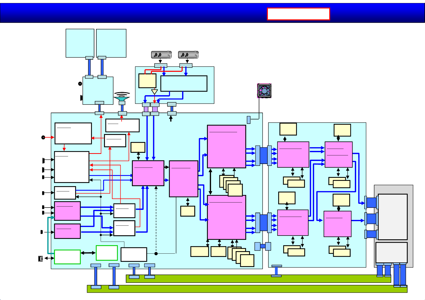
Block Diagram
Panasonic Internal
2014.11.12
14 /44
PC/DVI
AUDIO_IN
PC/Component
DVI
HDMI4
HDMI3
HDMI2
HDMI 1
DP
LAN
LED/IR (V1)
(TNPA6044)
IR Receive
Environment AI
LED
Line out
RS232C
AUDIOSW
・AUDIO Selector
IC2105
Audio
L/R
ADV7471
・ADC
・HDMI_RX
・LIP Sync
・Syc Selector(H/V)
IC2509
ADV7619
・HDMI_RX
IC4606
MN864778P
・HDMI_RX
・4K2K->2k2k x2
IC4606
STDP4320
・DP_RX
・4k2k->2k2k x2
Digital
Link
HDBaseT
・Digital link
IC2701
KEY (V2)
(TNPA6045)
Input
Menu
Volume Up/Down
Enter
Power SW
V22
V11
HX11
HX22
RS232C/Audio
(HX)
(TNPA6036)
HX37
A37
Analog OUT
SPDIF OUT
Audio
L/R
28.6363MHz
LAN MCU
・EPSON
IC2911
SPEAKERS
SP
A27
LV4924
・Audio Power AMP
IC2002
AK4384VT
・D/A
IC2116
L/R
PWM_OUT
ADV7619
・HDMI_RX
IC4603
ADV7619
・HDMI_RX
IC4602
C1ZBZ0004703
IC4013
A05
IC34002
SPI
32M
FPGA1
・Input Select
IC5510
CPG
A03A02
Selector
IC34005
IC34005
DS9
A9
A06
DS1 DS2
FPGA
・Digital Video Through etc
IC37000
DS10
A10
DS13
A13
F15V
LVDS
FPGA2
・R/L separate
・Add picture
IC5710
27MHz
(TNPH1113)
(TNPA6038)
SPI
128M
(A)
(DS)
EPROM
256k
BUS
8bit
FAN x 2 (A,FR)
LSI (Slave)
・I/P convert
・Sharpness
・INPUT Level
・Color Management
・WB Adjustment
・Resize
IC5001
DDR3
DDR3
1G
DDR3
1G
16bit
1G
16bit
DDR3
16bit
1G
16bit
LSI (Master)
・I/P convert
・Sharpness
・INPUT Level
・Color Management
・WB Adjustment
・Resize
・OSD
IC4001
FLASH
128M
DDR3
DDR3
1G
16bit
16bit
1G
DDR3
DDR3
1G
16bit
16bit
LVDS
LVDS
1G
A7
LVDS
LVDS
■FPGA 1
1) Input Select
2) Signal Frequency detection
■ FPGA2
1) R/L separate
2) ADD Picture (Overlap)
■LSI
1) RESIZE
2) I / P Convert
3) Contrast/Brightness
4) Sharpness
5) MENU OSD
6) Internal Signal generator
7) WB
■ FPGA3 is following
1) Square/Stripe Convert
3) Drive control of LCD panel
IC8701
SPI
32M
148.5MHz
5pair +CLK
FPGA3B
・田/川 conversion
FR16
IC8700
IC8407
SPI
32M
DDR3
1G 16bit
1G 16bit
DDR3
LVDS
A16
LVDS
LVDS
FPGA3A
LVDS
A15
A17
・田/川 conversion
IC8400
FR15
FR17
A5
DDR3
1G 16bit
1G 16bit
DDR3
IC9502
SPI
16M
PA168
(Master)
・Double Speed
IC9000
DDR3
1G 16bit
DDR3
1G 16bit
IC9002
SPI
16M
PA168
・Double Speed
IC9500
DDR3
1G 16bit
DDR3
1G 16bit
(TNPA6037)
Vx1
8Lane
Vx1
8Lane
(FR)
LCD PANEL
Vby1
FR2
CN2
Timing
controller
board
Vby1
FR3
CN3
CN1
CN1
Inverter
board
(Backlight)
CN1101
CN1201
CN201
CN101
1) System Control
2) Signal processing
P2
P2
P5
P6
Power Sub (TNPA6024AB)
Power Main (TNPA6024AA)
P5
P3
P4
P3
P4
Page 15
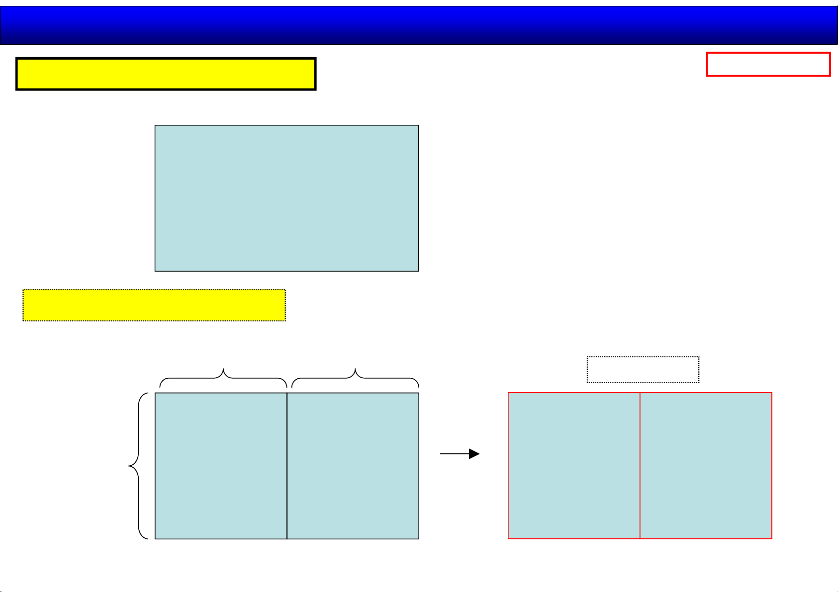
Signal Format
Input select = HDMI 1,2 / DP
3840 sample
2014.11.12
15 /44
Panasonic Internal
2160 line
Panel resolution
Input signal = 3840 / 50, 60p
1920 sample
2160 line
1920 sample
Display Image
Master
Signal processing
Slave
Signal processing
4K2K ⇒ (2Kx2K)x 2
Page 16
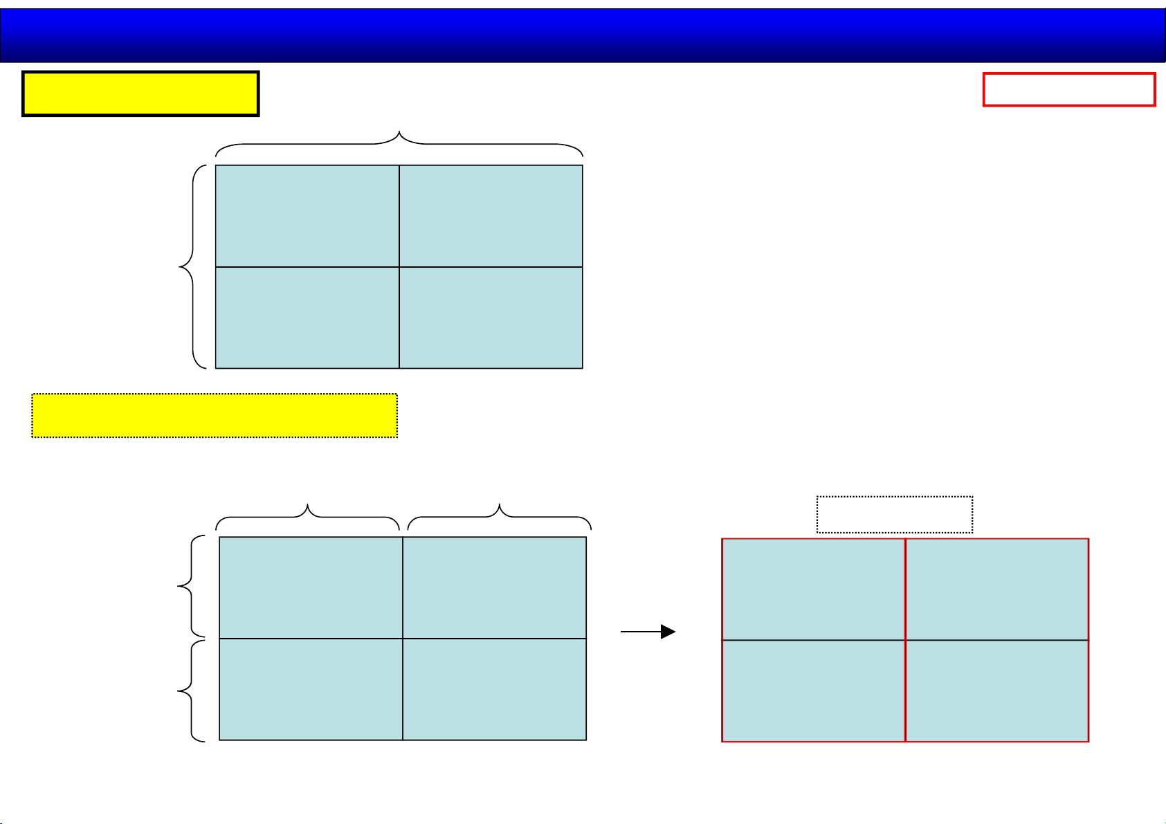
Signal Format
2014.11.12
16 /44
Input select = SDi
3840 sample
①
2160 line
Panel resolution
③
Input signal = 3840 / 50,60p
1920 sample
Panasonic Internal
②
④
1920 sample
1080 line
1080 line
SDi1
SDi3
①
③
(2Kx1K)x 4
SDi2
SDi4
②
④
Display Image
SDi1
①
SDi3
③
Master
Signal processing
SDi2
SDi4
Slave
Signal processing
②
④
Page 17
Generalserviceinformation
2014.11.12
17 /44
Panasonic Internal
GeneralInformationof4K
MainFeature
BlockDiagrams
Structure/Disassemble
ServiceInformation
Adjustment/Upgrade
Page 18
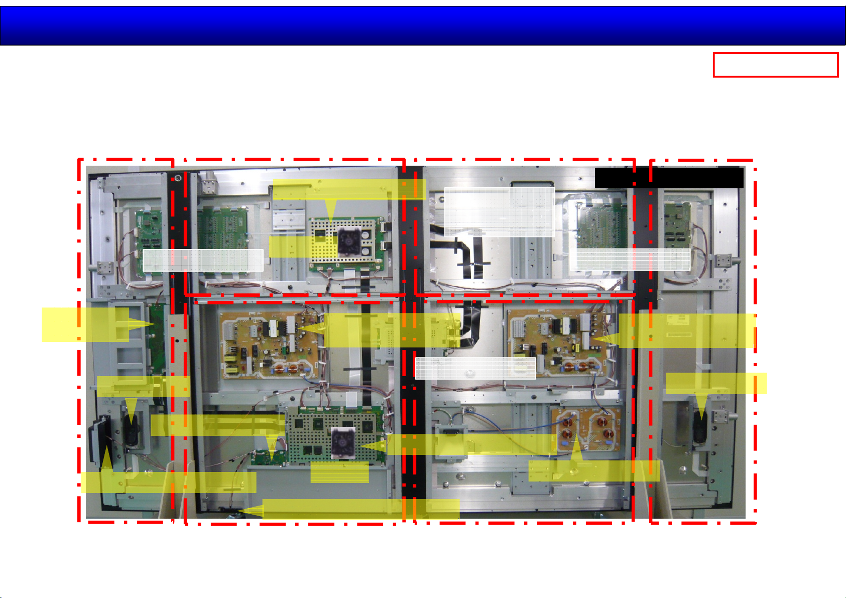
TH-98/84LQ70 Structure (1)
2014.11.12
18 /44
Panasonic Internal
Rear Cover(R)
Function slot
module(DS)
Speaker(R)
Power for LCD unit
Terminal module(HX)
Panel driver module(FR)
FAN (FR)
Main Power module AA
(P)
Rear cover(LT)
Video Signal
LCD MAIN P.C.B.
to LCD unit
Power for LCD unit
Rear cover(L)Rear cover(RT)
LCD module(Complete)
Power for LCD unit
Sub Power module AB
(P)
Speaker(L)
Power/Operation module(V2)
Signal processing module(A)
FAN (A)
LED/Photo detective module(V1)
Rear cover(RB)
Power (F)
Rear cover(LB)
Page 19
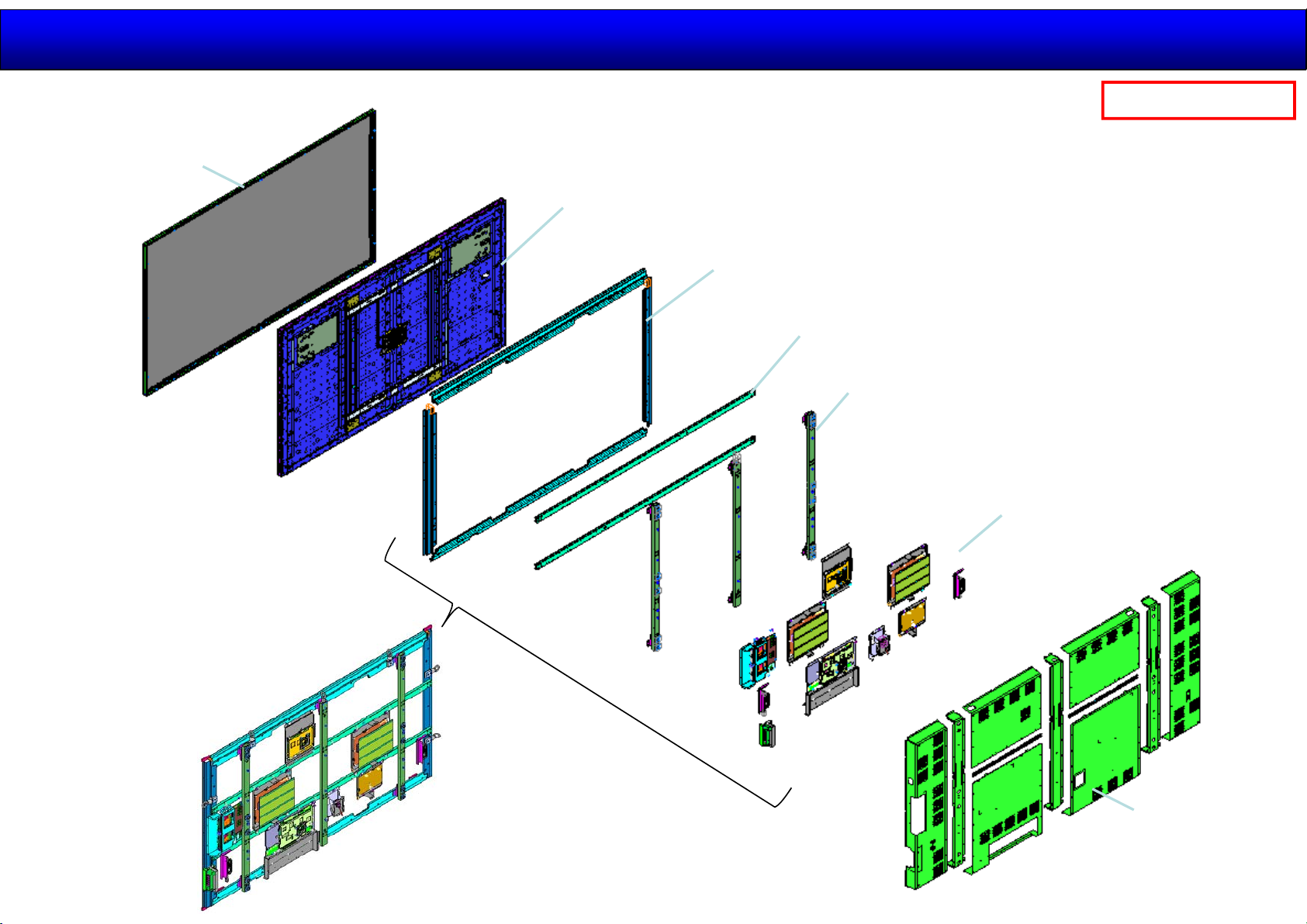
TH-98/84LQ70 Structure (2)
2014.11.12
19 /44
Panasonic Internal
Front cabinet
LCD unit (with LCD drive(T-con) and LED driver)
Half-Life period is 50,000 hours.
Rear frame LCD
Rear frame (H)
Rear frame (V)
P. C. B’ s
Rear cover
Page 20
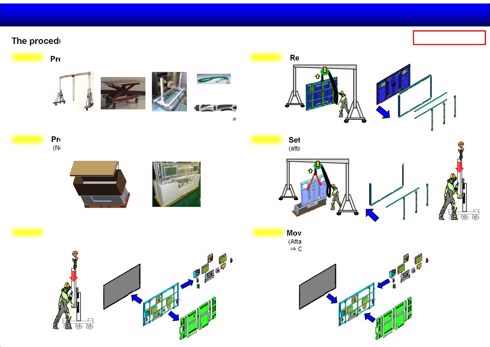
How to replace the panel
2014.11.12
20 /44
The procedure for replace the panel is as follows.
Step 0
Step 1
Preparation for the Jig
Lift and Crane
Preparation for replace the panel
(Not to take the LCD panel out of the carton box yet)
Jack x 2
Service Stand
Rope or wire
Electrical Screw
Driver
Step 3
Step 4
Panasonic Internal
Remove the all frame parts from defective unit
Set the new panel to the stand
(attach rear frame and rear frame LCD )
Step 2
Move to the defective unit to the service stand
Remove rear cover ⇒ Front Cabinet ⇒all PCB)
(
Step 5
Move to the all parts to the new panel
(Attach all PCB ⇒ Attach font Cabinet
⇒ Check the panel to turn ON the unit ⇒Attach rear cover⇒Finish )
Page 21
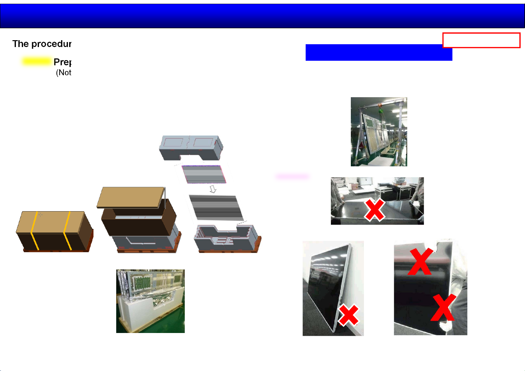
How to replace the panel
2014.11.12
21 /44
The procedure for replace the panel is as follows
Step1
Preparation for replace the panel
(Not to take the LCD panel out of the carton box yet)
<Shipping condition>
The replacement panel is shipped in carton
box with wooden pallet.
Panasonic Internal
How to handle LCD Panel
・Please handle the LCD panel in standing state with crane.
・Please work by three persons or more persons.
・Please work putting a glove and protective helmets.
Caution:
Do not have like photo.
Do not put LCD Panel
against a wall
Do not press down the
screen
Page 22
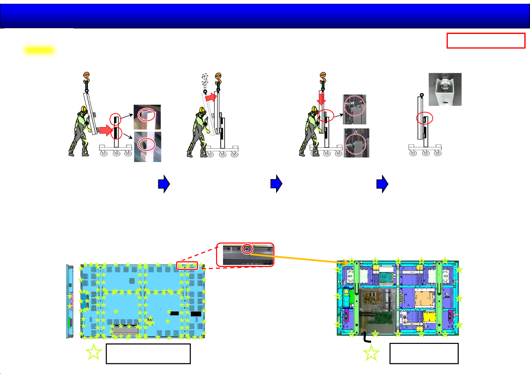
How to replace the panel
Step2
Move to the defective unit to the service stand
(to Remove Rear Cover/Front Cabinet)
2014.11.12
22 /44
Panasonic Internal
1. Approach the panel
to the stand and set
the lower hook to
lower hole of stand.
2. After setting the lower
hook the lower hole,
stand up the panel to
vertically.
3. After standing the
panel to vertically,
set the panel to
stand slowly.
(Insert the upper
hook to upper notch)
4. Finish
Remove Rear Cover
Remove the screw at 148 points for rear cover. Remove the screw at 16 points for Front cabinet.
Then disconnect cable which is connect to the cabinet block.
The screw located cut-out portion
of rear cover attach the front cabinet
and the frame.
THEL065Z : 148
[100±20 N・㎝]
THEL065Z : 16
[100 ±20 N・㎝]
Page 23
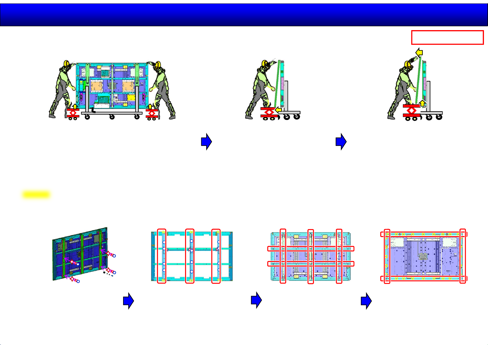
How to replace the panel
2014.11.12
23 /44
Remove front cabinet block
1. Install the jack at right and left side
under the cabinet block.
Confirm the rattled upper cabinet block.
Step3
Remove the all parts from defective unit
2. After moving up 1~2mm the
front , move the jacks to front
direction.
Panasonic Internal
3. Jack up 10 mm the cabinet block.
Then move the upper cabinet
block to the front side to pass
the hook part.
Then set the cabinet block
against the wall temporarily .
1. Remove all PCB with metal fixture to disconnect the cables.
2. Remove the stand hook.
3. Remove the rear frame cover. 3. Remove the rear frame.
4. Remove the rear frame LCD.
Vertical → Horizontal
Page 24
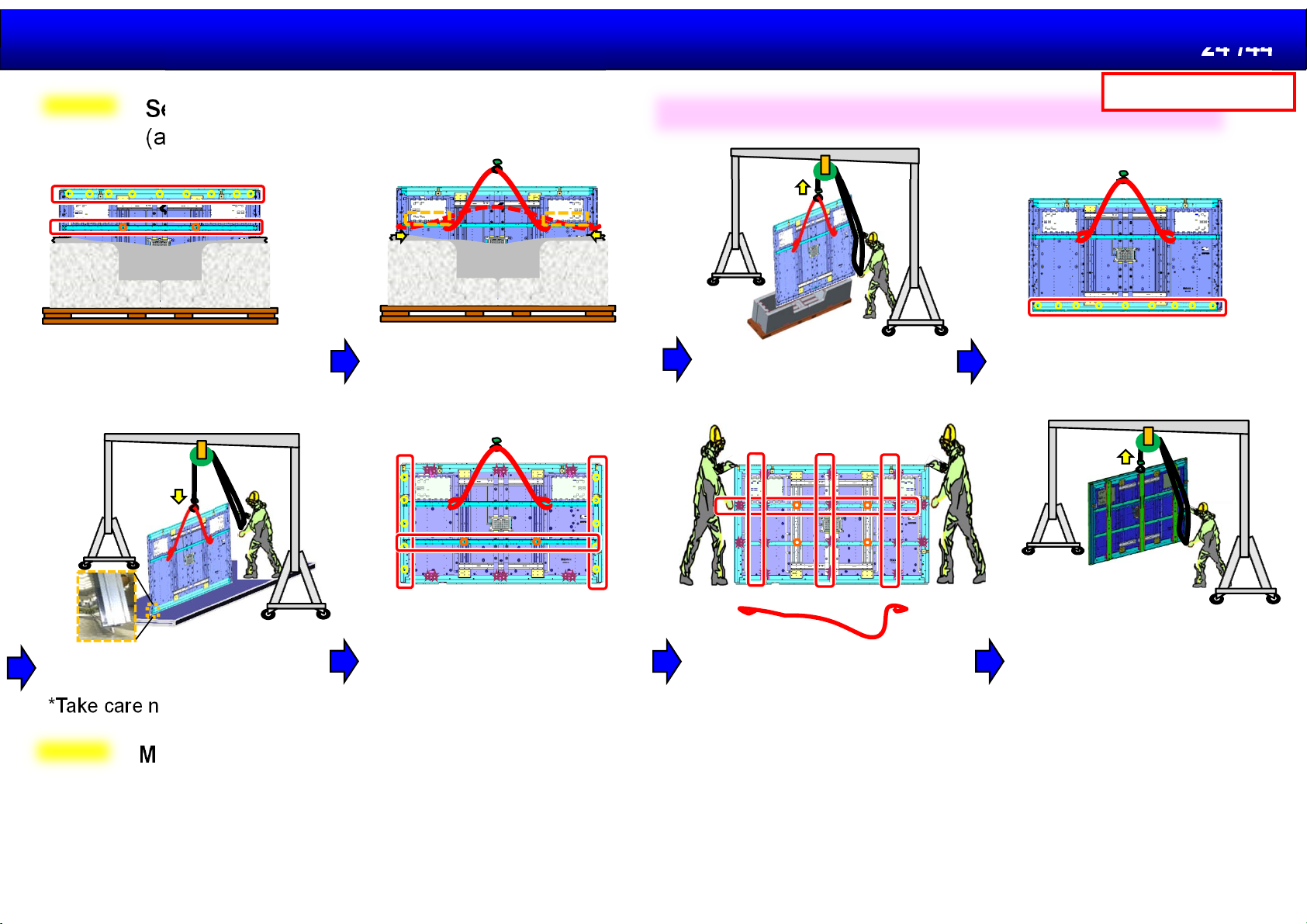
How to replace the panel
2014.11.12
24 /44
Step4
Set the new panel to the stand
(attach rear frame and rear frame LCD )
1. Attach the rear frame LCD(T)
and rear frame(H)(T) in standing
state in the carton box.
3. attach a rope or a wire
to the rear frame(H)(T) .
*Take care not to damage FFC
Caution:
1)Please handle the LCD panel in standing state with crane.
3. Pull up the LCD with
a crane out of the carton.
4. Attach the rear frame LCD(B)
in the hung state.
Panasonic Internal
5. Spread a cushion and put
down the LCD slowly .
*Take care not to damage LCD
Step5
Move to the all parts to the new panel
1. Attach all PCB with metal fixture and connect the cables.
2. Attach front cabinet block.
3. Check the panel to Turn ON the unit .
4. Attach all Rear cover.
5. Finish.
6. Attach the rear frame LCD
(RL) and rear frame(H)(B).
7. Remove the rope or wire to
remove rear frame(H)(T).
Then attach the rear frame(H)(T)
again and rear frame(V) .
8. Attach the rear frame cover
and stand hook.
Pull up the LCD panel with a
crane and set the stand.
Page 25
Generalserviceinformation
2014.11.12
25 /44
Panasonic Internal
GeneralInformationof4K
MainFeature
BlockDiagrams
Structure/Disassemble
ServiceInformation
Adjustment/Upgrade
Page 26
Service Mode
Panasonic Internal
2014.11.12
26 /44
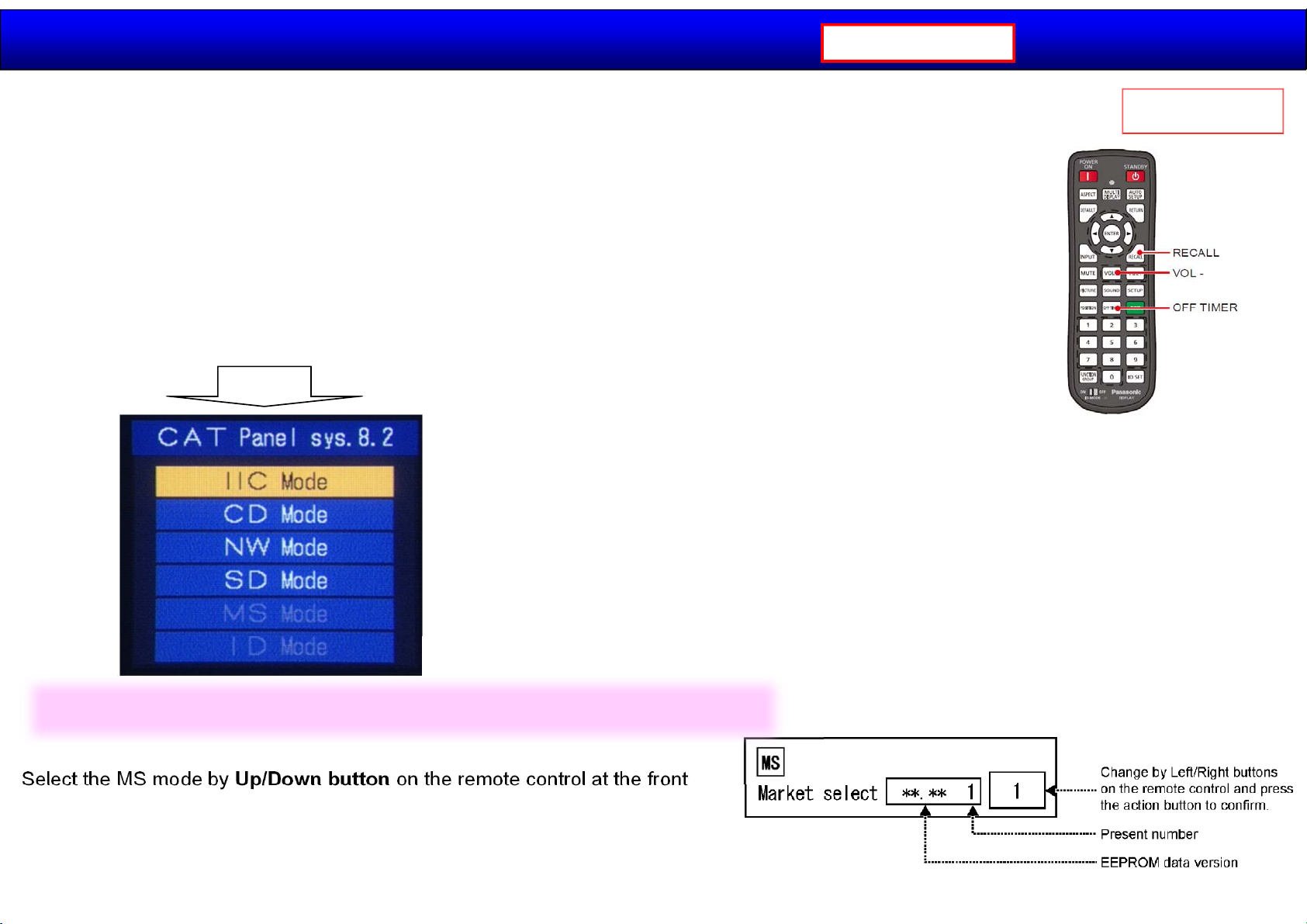
■how to access the CAT(Computer Aided Test) mode.
Method A Main unit + remote control operation
Press and hold the button on the right side of the unit and press the RECALL button
on the remote control 3 times quickly within 2 second.
Method B Remote control operation only
1. Set the OFF timer except for [0] minute by OFF TIMER button.
(30 minutes, 60minutes, 90 minutes)
2. Set the volume level of sound to 0 by VOL down button / -button.
3. Press the RECALL button more than 3 seconds before a volume display disappears.
Select each mode by Up/Down button on the remote control
・IIC/NW/SD Action
・CD/MS/ID Mute more than 3 seconds
To exit the CAT mode, turn the power off by main unit or a remote control.
As usual
Caution:
Market Select should be set after replacement of A-Board.
Select the MS mode by Up/Down button on the remote control at the front
page of CAT mode and then press the Mute button on the remote control
more than 3 seconds.
Switch Off and switch On then the data is changed.
Page 27
Service Mode (CD Mode)
Panasonic Internal
2014.11.12
27 /44
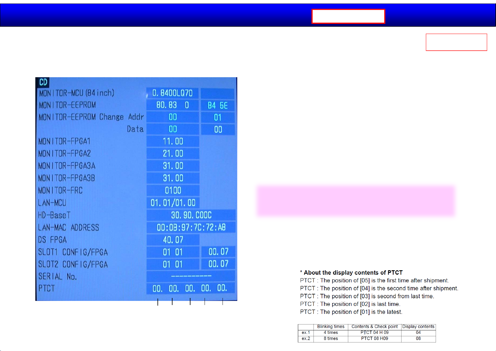
All software versions are displayed In the CD Mode.
Select the CD mode by Up/Down button on the remote control at the front page of CAT mode and then
press the Mute button on the remote control more than 3 seconds.
Point:
The upgrade tool of software is provided
on the service support website.
As usual
PTCT position:
SOS history
【01】【02】【03】【04】【05】
Page 28
Service Mode (NW Mode)
Panasonic Internal
2014.11.12
28 /44
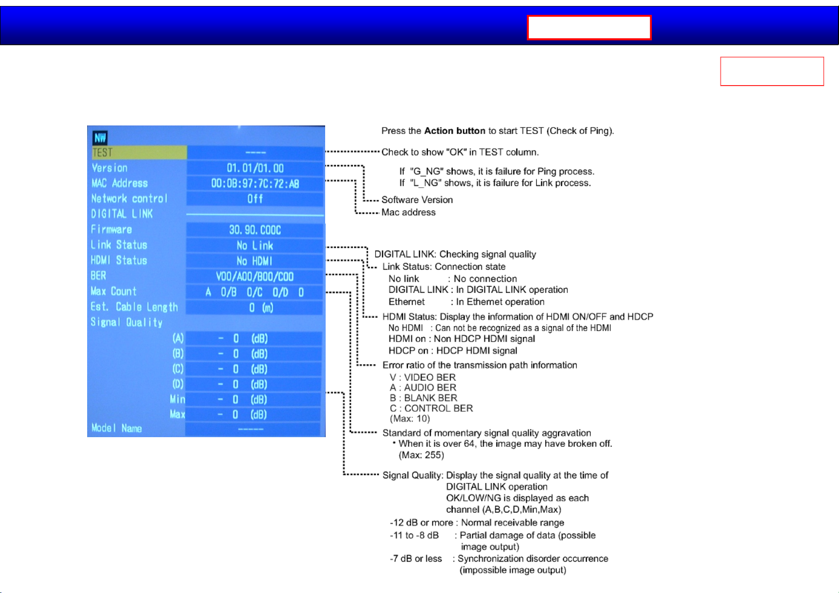
It’s possible to check the network connection In the NW Mode.
Select the NW mode by Up/Down button on the remote control at the front page of CAT mode
and then press the Action button on the remote control.
As usual
In the case of 100-meter DIGITAL LINK cable,
they should be -12dB or less.
Page 29
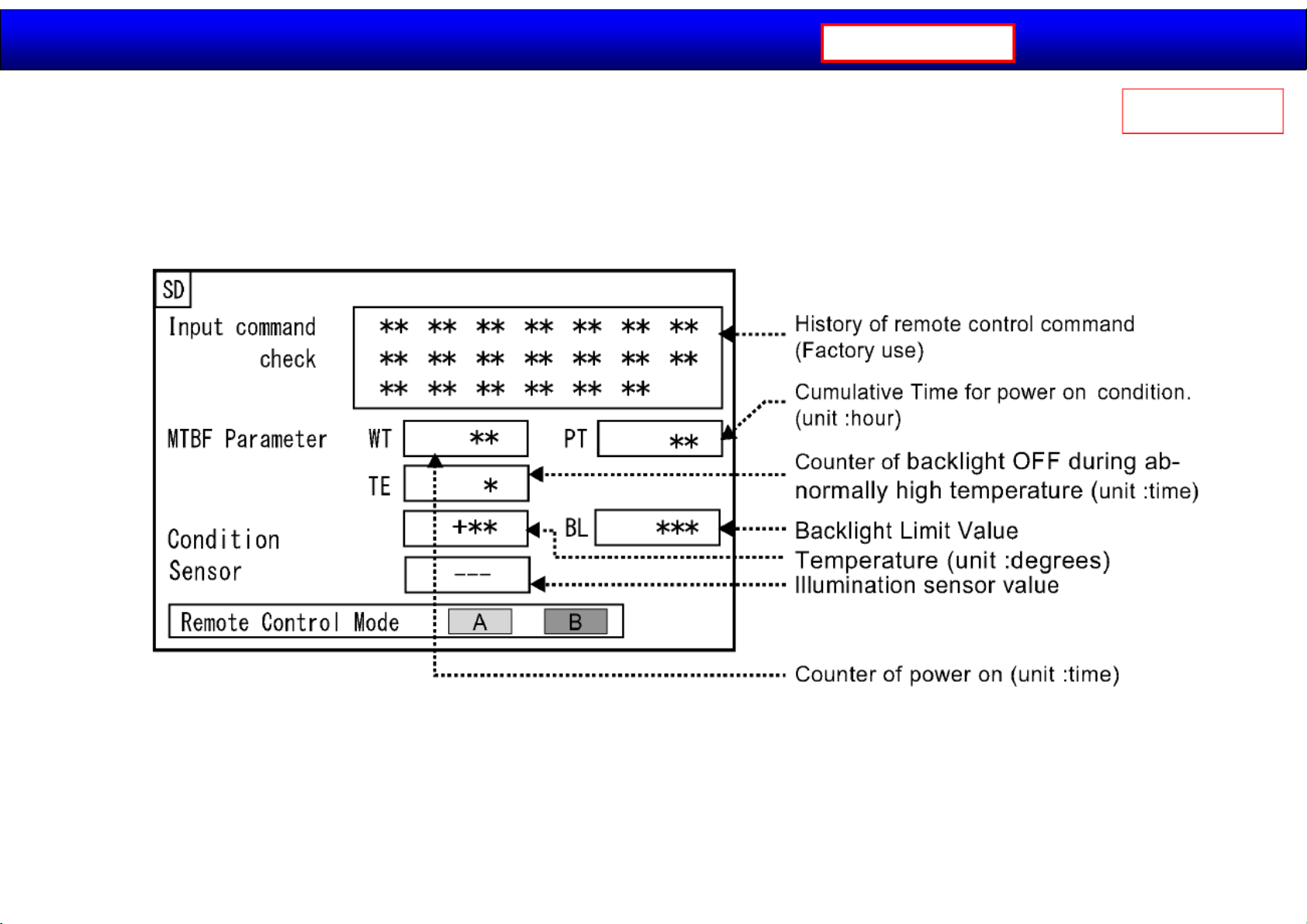
Service Mode (SD Mode)
It’s possible to check Counter of power on/Cumulative Time for power on condition/Counter of
Backlight OFF during abnormally high temperature In the CD Mode.
Select the SD mode by Up/Down button on the remote control at the front page of CAT mode and then
press the Action button on the remote control.
Panasonic Internal
2014.11.12
29 /44
As usual
Page 30
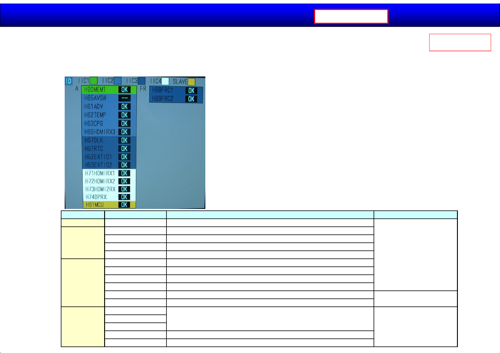
Service Mode (ID Mode)
It’s possible to narrow down the defect circuit based on the results of self check in the ID Mode.
Select the ID mode by Up/Down button on the remote control at the front page of CAT mode and then press the
Mute button on the remote control more than 3 seconds.
2014.11.12
Panasonic Internal
30 /44
As usual
To exit the ID mode, press the Return button on the remote control.
To exit the CAT mode, turn the power off by main unit or a remote control.
IIC1
IIC2
IIC3
IIC4
Indicator Symptoms Check point
H90MEM1 Setting values are not stored.
H61ADV No sound. The image does not appear correctly in HDMI4 or PC input.
H62TEMP Temperature abnormality.
H63CPG Picture abnormality.
H66HDMIRX3 The image and the sound do not appear correctly in HDMI3.
H67DLK LAN and DIGITAL LINK communication are not possible.
H51RTC Timer function does not work.
H52EXT01 No image/No sound in HDMI1,2,3,4 and DIGITAL LINK.
H53EXT02 Unit does not start.
H68FRC1 No picture
H68FRC2 No picture
H71HDMIRX1
H72HDMIRX2
H73HDMI2RX
H74DPRX Picture/Sound by DISPLAYPORT do not appear correctly.
H91MCU Right half or full screen do not appear correctly.
The image and the sound do not appear correctly in HDMI1,2 and DIGITAL LINK
and DISPLAYPORT.
A-Board
FR-Board
A-Board
Page 31
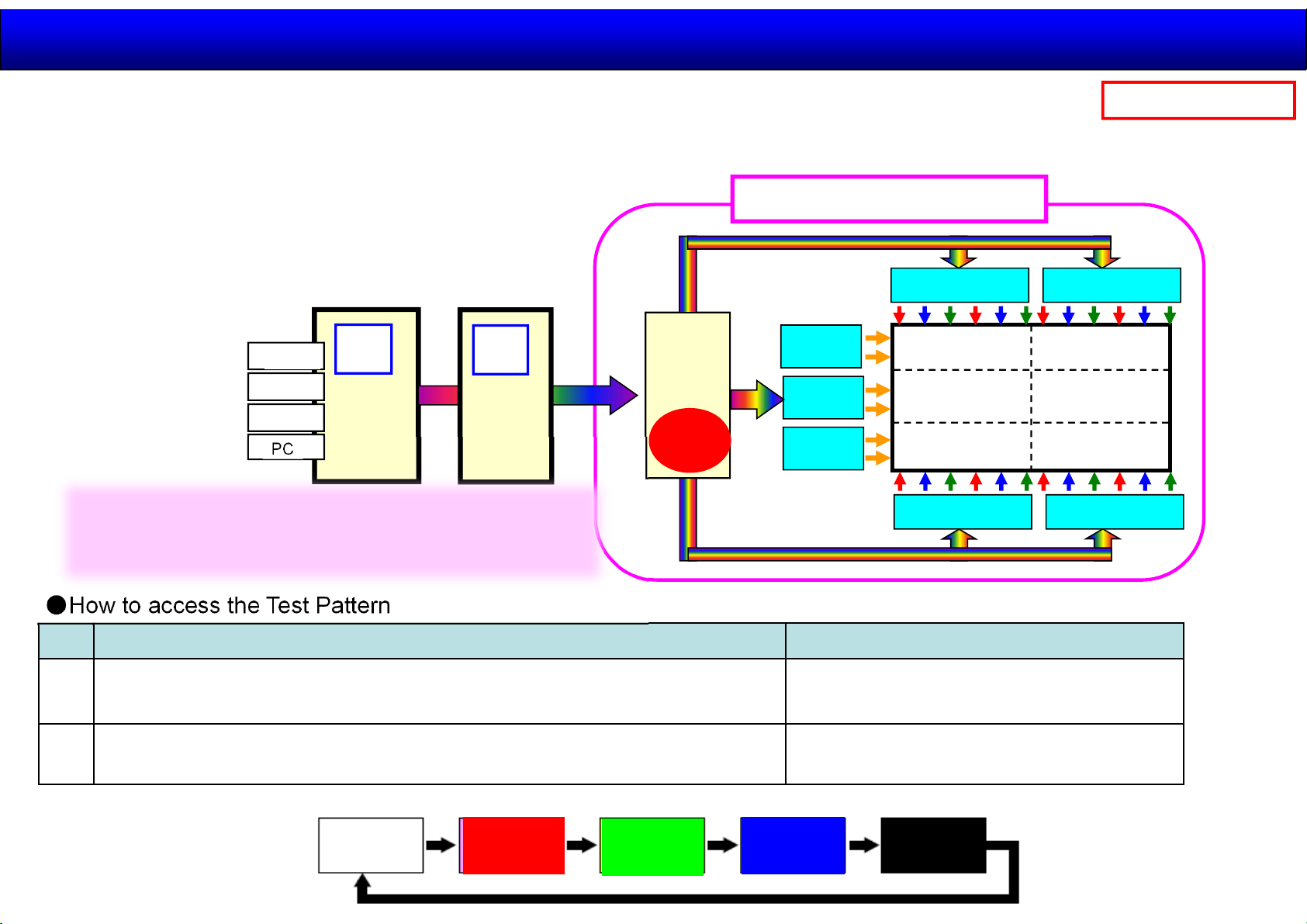
Clarify by test pattern
The failure in a video image are caused by failure of A module or FR module or LCD Panel module.
LCD module includes T-CON(Timing Controller) Board and Gate/Source driver IC .
2014.11.12
31 /44
Panasonic Internal
T-CON Board converts video signal to LCD panel signal.
Gate/Source driver IC output Vertical/Horizontal signal.
D/P
HDMI
DS
PC
A
FR
Point:
The test pattern is outputted from T-CON Board.
When the test pattern has no problem,
T-CON Board(LCD Panel Module) also has no problem.
●How to access the Test Pattern
How to access the Test Pattern How to exit
T-CON
Test
Pattern
LCD Panel Module
Source Driver IC
Gate
Driver IC
Gate
Driver IC
Gate
Driver IC
LCD Panel
Source Driver IC Source Driver IC
Source Driver IC
①
②
Press and hold the button on the right side of the unit and press
the RETUN button on the remote control 3 times quickly within 2 second
Remote control
[RECALL]→[RETURN]→[DEFAULT(more than 3seconds)]
●Display Pattern
WHITE
Power off the main unit.
Power off automatically after 10 seconds.
RED GREEN BLUE BLACK
Page 32
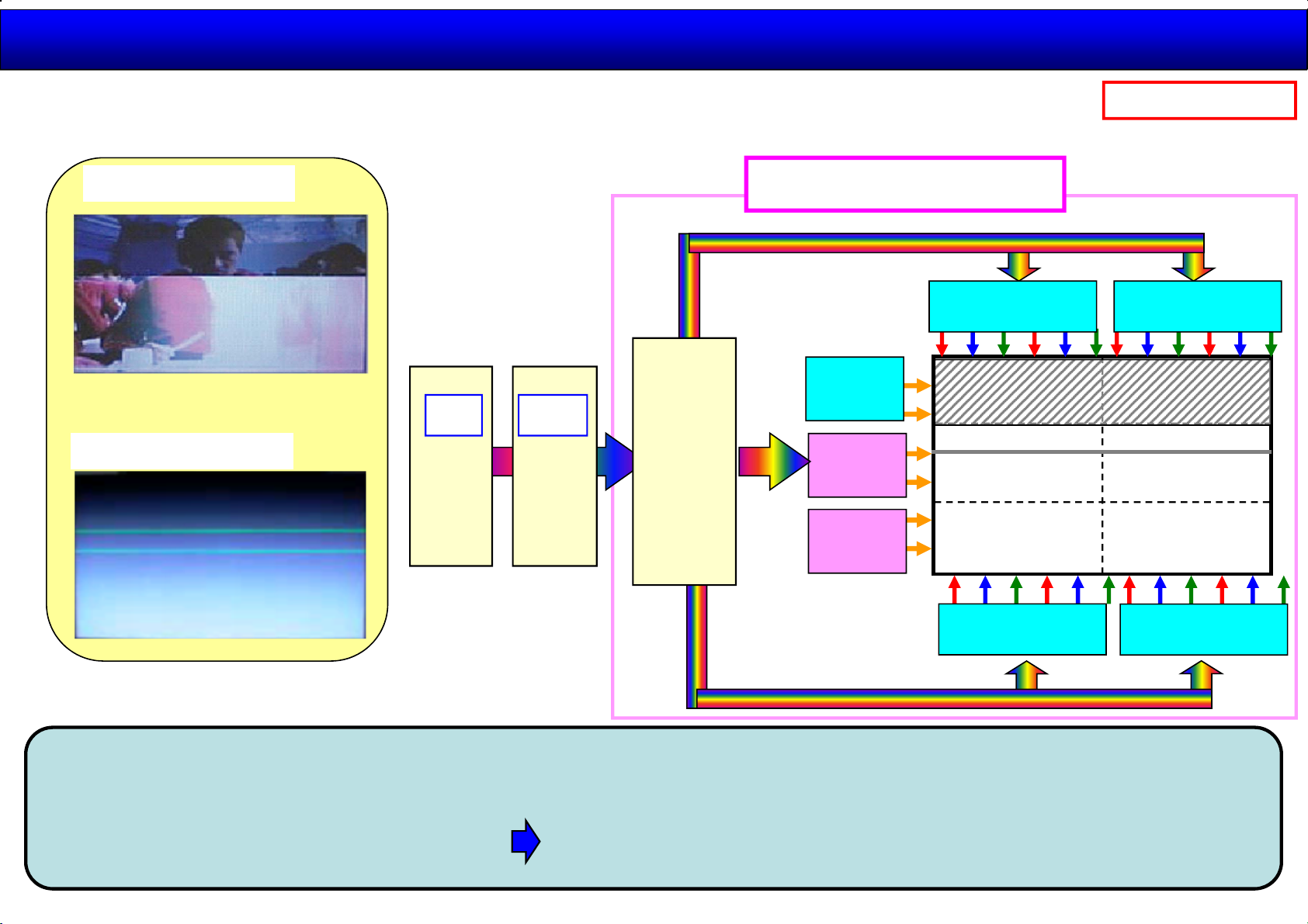
The failure of video image:Horizontal axis direction
The Horizontal Bar/Line:Panel Replacement
2014.11.12
32 /44
Panasonic Internal
Horizontal Bar
Horizontal Line
A
FR
T-CON
LCD Panel Module
Source Driver IC Source Driver IC
Gate
Driver IC
Gate
Driver IC
Gate
Driver IC
Source Driver IC
Source Driver IC
The horizontal axis direction signal is made by T-CON Board and output to the LCD panel to branch
each line via gate driver IC. Therefore The horizontal Bar/Line is caused by the failure of gate driver IC.
Gate driver IC is unable to replace. LCD panel module is required to replace.
Page 33
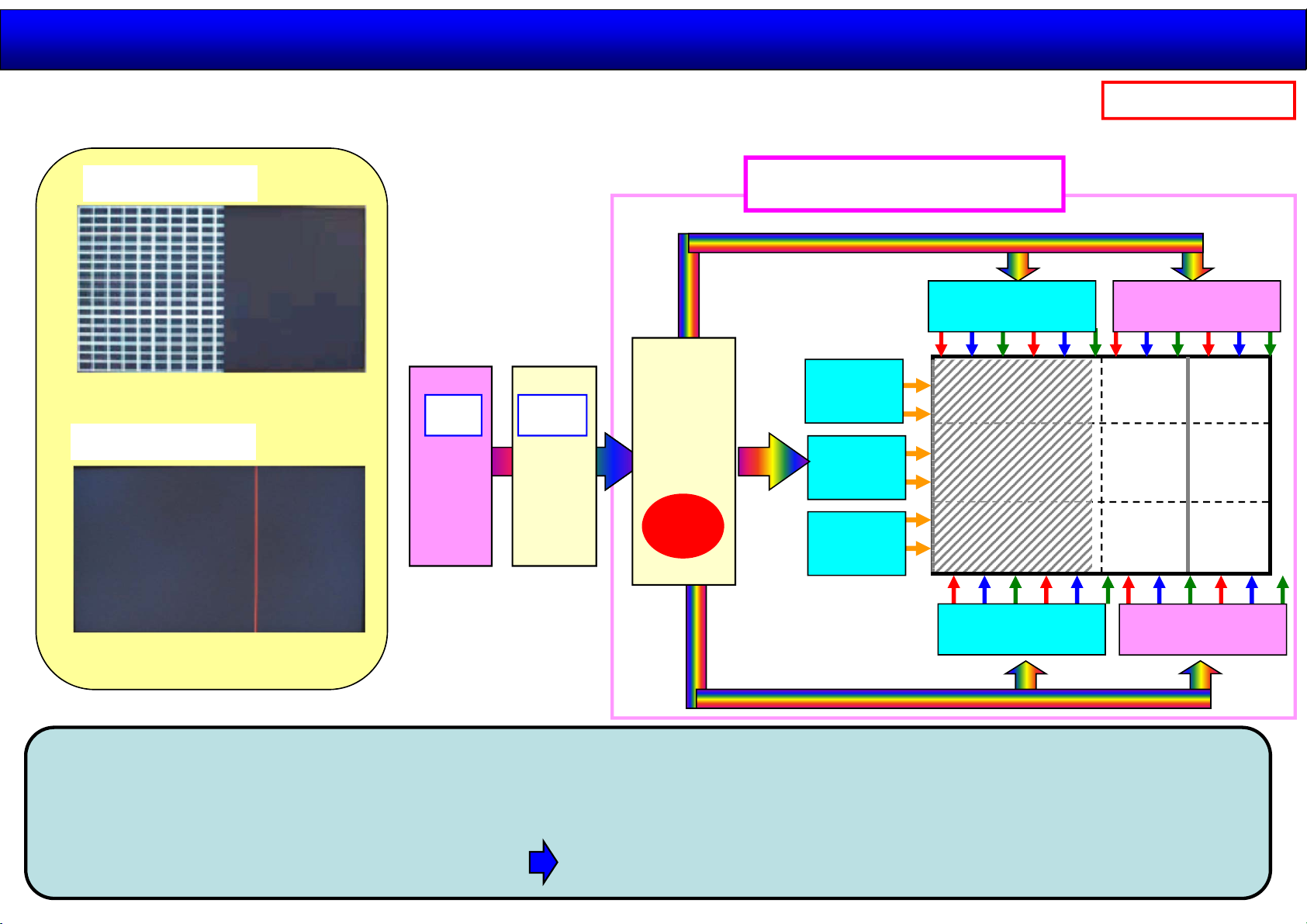
The failure of video image:vertical axis direction(1)
Some Vertical Bar/Line:Panel Replacement
2014.11.12
33 /44
Panasonic Internal
Vertical Bar
Vertical Line
A FR
*In case of like noise,
there is also possibility of
main(A) P.C.B..
⇒Clarify by test pattern.
T-CON
Test
Pattern
LCD Panel Module
Source Driver IC Source Driver IC
Gate
Driver IC
Gate
Driver IC
Gate
Driver IC
Source Driver IC
Source Driver IC
The vertical axis direction signal is made by A-Board Board and output to the T-CON Board.
The T-CON Board controls the input timing and output signal to the LCD panel to branch each line
via source driver IC. Therefore The vertical Bar/Line is caused by the failure of source driver IC.
Source driver IC is unable to replace. LCD panel module is required to replace.
Page 34
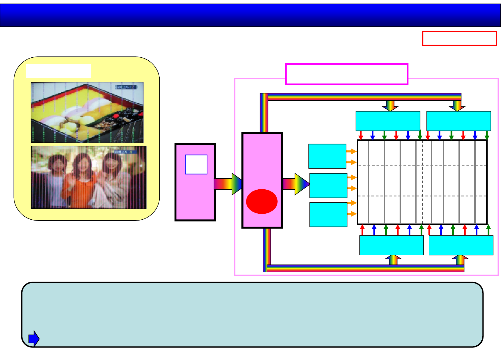
The failure of video image:vertical axis direction(2)
Overall Vertical Bar/Line:Main(A) or Panel Replacement
2014.11.12
34 /44
Panasonic Internal
複数の縦線
A
T-CON
Test
Pattern
LCD Panel module
Source Driver IC Source Driver IC
Gate
Driver IC
Gate
Driver IC
Gate
Driver IC
Source Driver IC
Source Driver IC
When a lot of vertical lines are placed at equal spaces, A-Board or T-CON Board of LCD panel is
failed.
There are both possibility of A-Board and T-CON Board. Please clarify by the test pattern.
The test pattern is outputted from T-CON Board.
When the test pattern has no problem, T-CON Board(LCD Panel Module) also has no problem.
Page 35
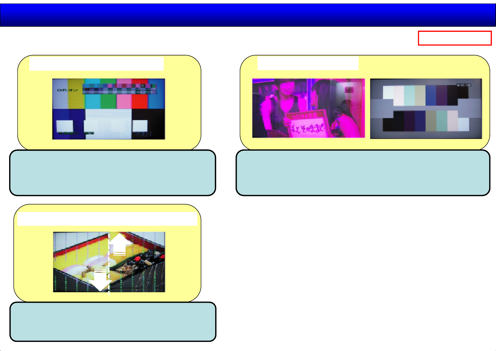
The failure of video image:Particular part
The failure of video image :Main(A) P.C.B
2014.11.12
35 /44
Panasonic Internal
OSD display abnormality
OSD (On Screen Display) is superimposed in
the signal processing IC of A-Board.
Therefore A-Board is failed.
Video image shift (Vertical axis direction)
Color abnormality
Color abnormality is the trouble in the signal processing.
Therefore A-Board is failed.
Please clarify by the test pattern.
Video image shift of vertical axis direction is
the trouble in the signal processing.
Therefore A-Board is failed.
Page 36
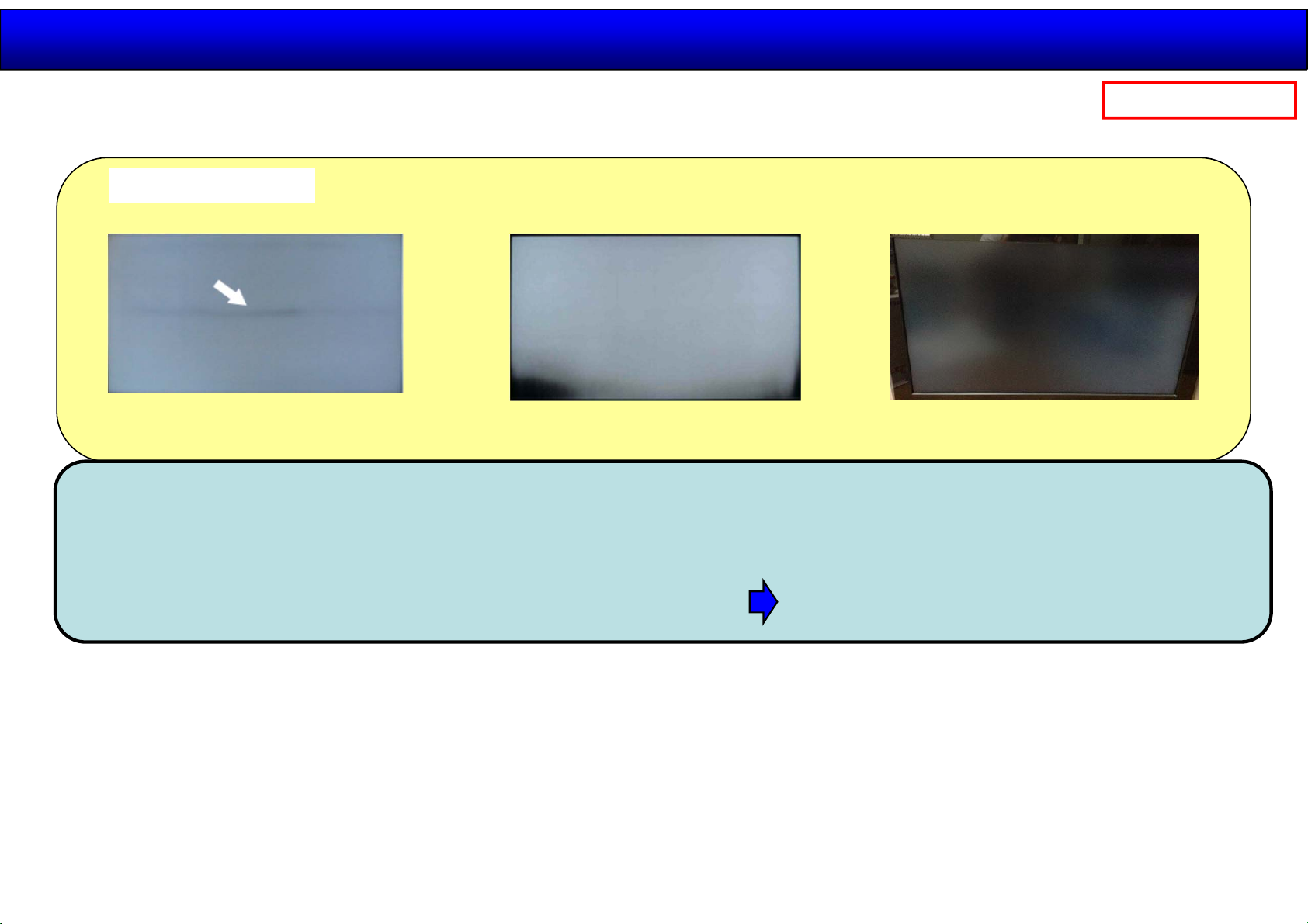
The failure of video image:Nonuniformity
Nonuniformity :Panel replacement
Nonuniformity
2014.11.12
36 /44
Panasonic Internal
The nonuniformity is caused by the failure of the backlight or the optical sheets in the LCD module.
These failures are supposed to be caused by strong impact force such as drop or mechanical
deformation.
The backlight or the optical sheets are unable to replace. LCD panel module is required to replace.
Page 37
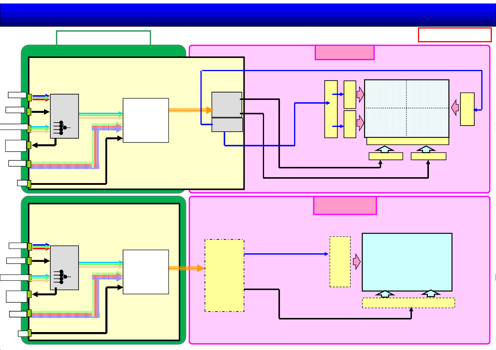
Reference ( PDP vs LCD)
2014.11.12
37 /44
PC IN
Video
Component
Monitor
OUT
HDMI
LAN
Signal processing
IC
Input
switching
LSI
Signal processing
Format Conversion
Resize
OSD
Main Micon
A
A
IC
Sub Field
Convert
Test Pattern
Discharge
Control
SUS Drive Control
Scan Drive Control
Picture Data
PDP Panel
SC
SU
SD
LCD Panel module
Panasonic Internal
SS
Data driver IC
C1 C2
PC IN
Video
Component
Monitor
OUT
HDMI
LAN
IC
Input
switching
LSI
Signal processing
Format Conversion
Resize
OSD
Main Micon
T-CON
Test pattern
Scan Drive Control
Picture Data
Gate
Driver
IC
LCD Panel
LCD パネル
Source Driver IC
Page 38
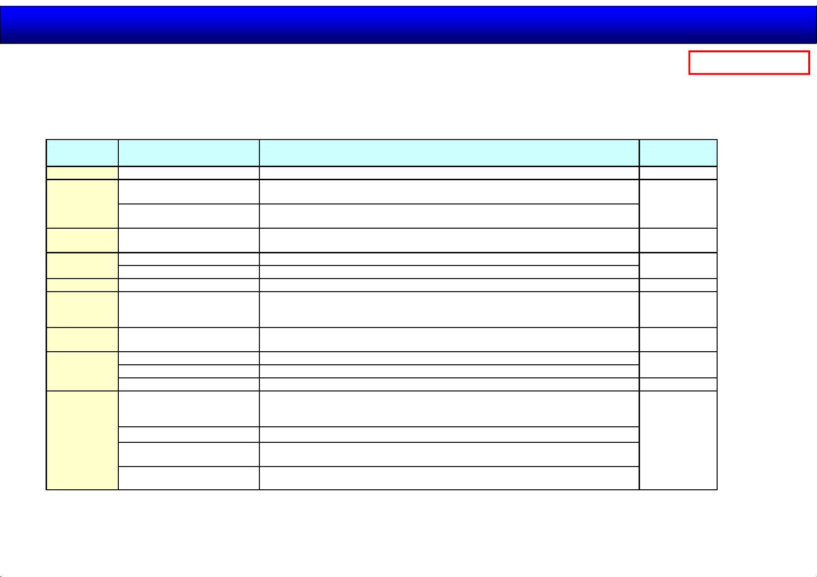
2014.11.12
Power LED Blinking timing chart
Panasonic Internal
38 /44
When an abnormality has occurred to the unit, the protection circuit operates and resets to the stand by mode.
At this time, the defective board can be identified by the number of blinks of the Power LED on the front panel of the unit.
Blinking times
1 PTCT 01 H09 PANEL SOS (Back light error) LCD Panel
2
4 PTCT 04 H09 PANEL12V SOS (Voltage drop from A-Board to Panel(TIMING CONTROLLER))
7
8 PTCT 08 H09 FRC SOS (Operation stop of FRC IC(Voltage drop, not start firmware)) FR-Board
10 PTCT 0A H09
11 PTCT 0B H09 FAN SOS
12
13
History display of the
detection of the abnormality
PTCT E2 H09
PTCT F2 H09
PTCT 07 H09 TEMPERATURE SOS (Highest TEMP)
PTCT 17 H09 TEMP SENSOR IC SOS
PTCT 1C H09 FPGA1 SOS of A-Board (Configuration Error)
PTCT 2C H09 FPGA2 SOS of A-Board (Configuration Error)
PTCT 3C H09 FPGA3 SOS of A-Board (Configuration Error) FR-Board
PTCT 0D H09
PTCT 1D H09 REGULATOR SOS of A-Board (Voltage drop of 5V )
PTCT 2D H09
Contents Check point
POWER SOS (Voltage drop from P-Board to A-Board)
・A +15V drop
POWER SOS (Voltage drop from P-Board to A-Board)
・F +15V drop
DS SOS (Voltage drop of below)
・SLOT3.3V,SLOT9V,LAN14V,SLOT5V
・SLOT SOS
REGULATOR SOS
・9V、1.5V、5V、9V、FPGA1_1.0V、FPGA1_1.8V、FPGA1_3.3V、FPGA2_1.0V、MGT1_1.0V、
MGT1_1.2V、MGT2_1.0V、MGT2_1.2V
REGULATOR SOS
・F3.3V,、F1.2V、F1.2V_S、HDMI1.1V、HDMI3.3V、HDMI5V、LAN5V、DP1.2V、FR3.3V
P-Board
A-Board
A-Board
LCD Panel
A-Board
DS-Board
Slot-Board
FAN
A-Board
A-Board
A-Board
PTCT 4D H09 AUDIO_SOS
Page 39
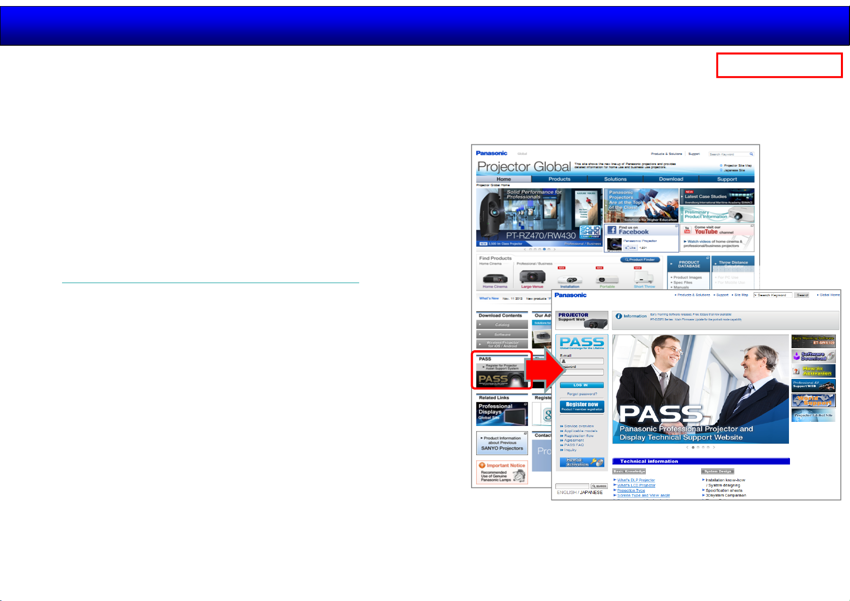
Service material and Software Download
VSBD supply Service material and Software of TH-98/84LQ70 on VSBD PASS website.
[Item]
· Service Manual · Supplement Service Manual · Parts News
· Service Software · Firmware
[Location]
Projector PASS website
1.Open projector website .
2014.11.12
39 /44
Panasonic Internal
[Projector website]
(http://panasonic.net/avc/projector/index.html)
2.Click link of [Projector PASS].
[How to download]
Basic procedure is the same as Professional AV PASS website.
[Projector
PASS]
Page 40
Generalserviceinformation
2014.11.12
40 /44
Panasonic Internal
GeneralInformationof4K
MainFeature
BlockDiagrams
Structure/Disassemble
ServiceInformation
Adjustment/Upgrade
Page 41
2014.11.12
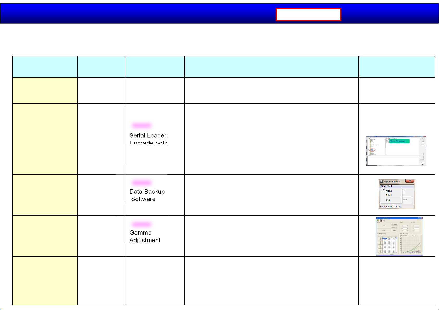
Upgrade & Adjustment items
Panasonic Internal
When the following components in this monitor are replaced, adjustments are required. Adjust each item according
to the table as below.
41 /44
Adjustment
Items
Confirmation
Firmware
upgrade
EEPROM data
transfer
Replaced
parts
- Signal generator
-
A Board
Tool Details Remarks
New
Serial Loader:
Upgrade Software
New
Data Backup
Software
For only confirmation
Signal generator or 3G-SDI, HDMI and Display Port.
* 4K signal generator is not required for repair.
Similar procedure and tool as PDP Loader.
The following firmware are stored in each IC.
1) Monitor MCU : IC4001 (Master)
2) FPGA1 : IC5510
3) FPGA2 : IC5710
4) FPGA3 : IC8700,8400
5) FRC : IC9000
6) LAN MCU : IC2911 (Master)
7) EEPROM
Similar procedure and tool as BT-4LH310.
TH-98/84LQ70 is equipped with EEPROM (A-Board).
The following data are stored in EEPROM.
User menu and Service menu GAMMA adjustment data
Picture adjustment data Hour meter information etc.
The version number of
MCU and FPGA can be
confirmed in the Service
mode.
Writing and saving
LCD Panel data
LCD GAMMA
Measurement
LCD Panel
A Board
As necessary
New
Gamma
Adjustment
Software
Display Color
analyzer
Similar procedure and tool as BT-4LH310.
When replacing LCD panel, the central gamma data can be
uploaded.
VSBD will supply the central gamma data ofTH-98/84LQ70
on VSBD PASS website.
SimilarprocedureandtoolasBT‐LH2550/LH2170.
·Justforthe casethatservicecenterhasCA‐310,
thismeasurementispossible.
·Itisnotrequiredforregularserviceoperation.
Customer canadjustLCD
GammaCalibrationvia
DisplayColor
Thisadjustment
procedureiswritteninthe
operatingInstruction.
Analyzer.
Page 42
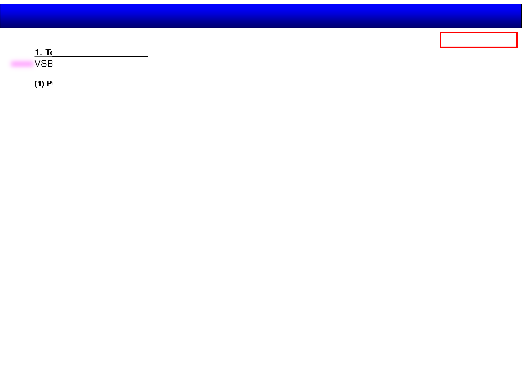
How to update the software
1. Tools and Preparation
2014.11.12
42 /44
Panasonic Internal
New
VSBD supply the Software Loader and Software of TH-98/84LQ70 on VSBD PASS website.
(1) PC
used for firmware transforming
<Specification>
- Windows 7
- Serial communication port, standard RS-232C/Dsub9
- USB can be used if no Dsub9 connector (USB-Dsub9 converter is necessary).
(2) RS232C cable
Straight cable, “Female/ Female” plug for DISPLAY connection
(3) Monitor software loader (application to be installed in the PC beforehand)
Serial Loader V1.0.0
(4) Updating data・・・ Extract the software and file package to your favorite directory on your computer.
1. MCU (Main CPU)
2. EEPROM
3. FPGA 1
4. FPGA 2
5. FPGA 3 A/B
6. FRC
7. LAN MCU
(5) Extract the software and file package to your favorite directory on your computer.
(6) Connect the serial terminal (SERIAL-IN) and PC with an RS-232C cable.
(7) Set “CONTROL I/F SELECT” to “RS-232C” in “NETWORK SETTINGS” .
Page 43
How to update the software
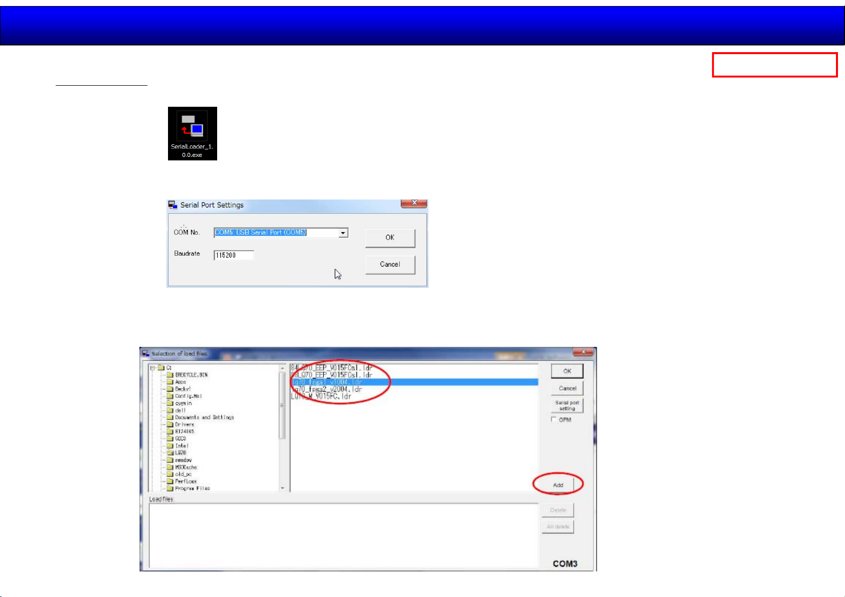
2. Procedure
1. Start up the updating software [SerialLoader.exe].
2. Choose available COM port with pull down menu and click [OK].
The baudrate should be used with "115200".
3. On the left window, browse and select a folder where the updating file is stored.
2014.11.12
43 /44
Panasonic Internal
The firmware file is listed on the right window and select it then click [Add].
The selected firmware will listed on the bottom window.
3-1 Select FPGA1 data.
Ex : lq70_fpga1_v****.ldr
Click “Add” button.
3-2 Select FPGA2 data.
Ex : lq70_fpga2_v2xxx.ldr
Click “Add” button.
3-3 Select EEPROM data.
Ex : LQ70_EEP_V****sl.ldr
Click “Add” button.
3-4 Select EEPROM data.
Ex : LQ70_M_V***.ldr
Click “Add” button.
Page 44
How to update the software
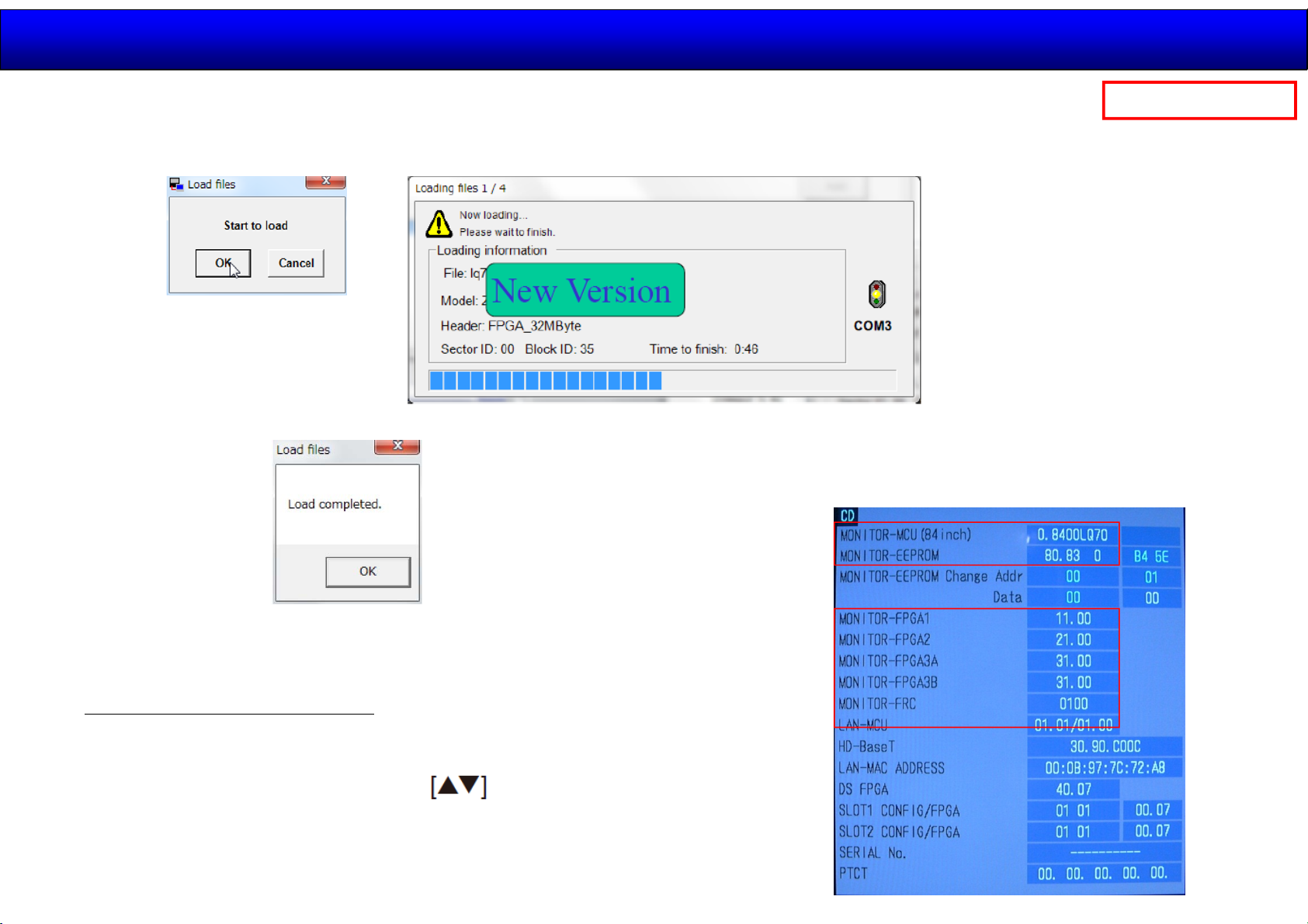
4. Click [OK]. The another confirmation window will appear and then click [OK] to start updating.
5. After finishing the updating, the window below appear and click [OK] to close the software.
2014.11.12
44 /44
Panasonic Internal
6. Turn of the Main switch and then on again.
Confirm the version number in the CD mode of CAT mode.
3. Confirmation of version
1. Display the CAT mode (Service Mode)
2. The CAT mode menu appears on the screen.
Select the [CD Mode] menu with buttons and press the
[MUTE] button for more than 3 seconds to enter the CD mode.
 Loading...