

Panasonic th-50lfc70, tH80lfc70e, tH65lfc70e, tH50lfc70e, tH80lfc70u operating instructions
...Page 1

T
U
T
U
T
U
T
E
T
E
T
E
Operating Instructions
.
Network Operations
FULL HD LCD Display (for business use)
H-50LFC70
H-65LFC70
H-80LFC70
H-50LFC70
H-65LFC70
H-80LFC70
l No.
TH-50LFC70W
TH-65LFC70W
TH-80LFC70W
nglish
Please read these instructions before operating your set
and retain them for future reference
Page 2
Contents
Before use
.
y
· · · · · · · · · · · · · · · · · · · · · · · · · · · · · · · · · · · · · · · · · · · · ·
·
·
·
·
)
men
·
N
·
AMX D.D
™
0
e
0
·
s
·
Accessing from the Web browser
l
Illustrations and screens in this Operating Instructions are images for illustration purposes, and may•
different from the actual ones.
Descriptive illustrations in this Operating Instructions are created mainly based on the 50 inch model
•
Read this rst!························································
Request Regarding Securit
What you can do · · · · · · · · · · · · · · · · · · · · · · · · · · · · · · · · · · · · · · · · · · · · · · · · · · · · · ·
Notes on Using Wireless Connection
otes on Using Wired LAN · · · · · · · · · · · · · · · · · · · · · · · · · · · · · · · · · · · · · · · · · · · · · ·
Check your computer··················································
Necessary environment for computers to be connected · · · · · · · · · · · · · · · · · · · · · · · · · · · · · · · ·
Connection · · · · · · · · · · · · · · · · · · · · · · · · · · · · · · · · · · · · · · · · · · · · · · · · · · · · · · · · · ·
Example of Network Connection (Wired LAN) · · · · · · · · · · · · · · · · · · · · · · · · · · · · · · · · · · · · · · ·
Example of Network Connection (DIGITAL LINK
Network Settings
Displaying the Network Settings
red LAN· · · · · · · · · · · · · · · · · · · · · · · · · · · · · · · · · · · · · · · · · · · · · · · · · · · · · · · · · · · · · · · · · · · · ·
Wireless LA
Name Change · · · · · · · · · · · · · · · · · · · · · · · · · · · · · · · · · · · · · · · · · · · · · · · · · · · · · · · · · · · · · · · · · ·
Control I/F Select · · · · · · · · · · · · · · · · · · · · · · · · · · · · · · · · · · · · · · · · · · · · · · · · · · · · · · · · · · · · · · ·
WEB Control
. · · · · · · · · · · · · · · · · · · · · · · · · · · · · · · · · · · · · · · · · · · · · · · · · · · · · · · · · · · · · · · · · · · · · · · ·19
Crestron Connected
etworktatus· · · · · · · · · · · · · · · · · · · · · · · · · · · · · · · · · · · · · · · · · · · · · · · · · · · · · · · · · · · · · · · · ·
Password· · · · · · · · · · · · · · · · · · · · · · · · · · · · · · · · · · · · · · · · · · · · · · · · · · · · · · · · · · · · · · · · · · · · · · 2
Multi-Liv
Live mode Cut In · · · · · · · · · · · · · · · · · · · · · · · · · · · · · · · · · · · · · · · · · · · · · · · · · · · · · · · · · · · · · · · ·
DIGITAL LINK statu
Digital Interface Box· · · · · · · · · · · · · · · · · · · · · · · · · · · · · · · · · · · · · · · · · · · · · · · · · · · · · · · · · · · · ·
DIGITAL LINK mode·····························································
Extron XTP
eset · · · · · · · · · · · · · · · · · · · · · · · · · · · · · · · · · · · · · · · · · · · · · · · · · · · · · · · · · · · · · · · · · · · · · · · · ·
u
5
2
19
19
19
2
2
Connecting with Wired LAN············································
Computer operation · · · · · · · · · · · · · · · · · · · · · · · · · · · · · · · · · · · · · · · · · · · · · · · · · · · · · · · · · · · · ·
Connecting with Wireless LAN ·········································
Computer operation · · · · · · · · · · · · · · · · · · · · · · · · · · · · · · · · · · · · · · · · · · · · · · · · · · · · · · · · · · · · ·
· · · · · · · · · · · · · · · · · · · · · · · · · · · · · · · · · · · · · · · · · · · · · · · · · · · ·2
· · · · · · · · · · · · · · · · · · · · · · · · · · · · · · · · · · · · · · · · · · · · · · · · · ·
sing Web Browser Control · · · · · · · · · · · · · · · · · · · · · · · · · · · · · · · · · · · · · · · · · · · · ·2
JLink™ Protoco
rademarks · · · · · · · · · · · · · · · · · · · · · · · · · · · · · · · · · · · · · · · · · · · · · · · · · · · · · · · · · ·5
4
Page 3

f
g
:
.
.
.
:
y
.
:
y (
.
>
.
y
0
y
ca
:
g
Read this rst!
FCC and IC STATEMENT
This equipment has been tested and found to comply with the limits for an Other Class B digital device, pursuant to
Part 15 of the FCC Rules. These limits are designed to provide reasonable protection against harmful interference in
a residential installation. This equipment generates, uses and can radiate radio
and used in accordance with the instructions, may cause harmful interference to radio communications. However,
there is no guarantee that interference will not occur in a particular installation. If this equipment does cause harmful
interference to radio or television reception, which can be determined by turning the equipment off and on, the user
is encoura
eorient or relocate the receiving antenna
•
ncrease the separation between the equipment and receiver
•
onnect the equipment into an outlet on a circuit different from that to which the receiver is connected.•
onsult the Panasonic Service Center or an experienced radio/Display technician for help
•
FCC Caution
o assure continued compliance, follow the attached installation instructions and use only shielded
interface cables when connecting to peripheral devices. Any changes or modi cations not expressly
approved b
FCC and Industry Canada (IC) RF Exposure Warning
ed to try to correct the interference by one or more of the following measures
Panasonic Corp. of North America could void the user’s authority to operate this device
his Display is provided with built-in transmitter: Wireless LAN Adapter with FCC ID:•
H8N-WLU5150/IC ID:1353A-WLU5150;
his transmitter complies with FCC and IC radiation exposure limits set forth for an uncontrolled•
nvironment for mobile use with minimum 8 inches (20 cm) spacing requirement between transmitter
and all person’s bod
eration
Other third-party wireless transmitters should not be used as they have not been RF exposure •
valuated for use with this Display and may not comply with RF exposure requirements.
excluding extremities of hands, wrist and feet) during wireless modes of
requency energy and, if not installed
nly for wireless LAN if capable of transmission in the 5.15 ~ 5.25 GHz frequency band
This product is restricted to indoor use due to its operation in the 5.15 to 5.25 GHz frequency range.
CC and IC require this product to be used indoors for the frequency range 5.15 to 5.25 GHz to reduce the
otential for harmful interference to co-channel Mobile Satellite systems. High power radars are allocated as
rimary users of the 5.25 to 5.35 GHz and 5.65 to 5.85 GHz bands. These radar stations can cause interference
with and/or damage this product
FCC Declaration of Conformit
Model: TH-50LFC70U, TH-65LFC70U, TH-80LFC70U
esponsible Party: Panasonic Corporation of North America
Two Riverfront Plaza, Newark, NJ 07102-549
Contact Source: Panasonic System Communications Compan
f North Ameri
1-877-655-2357
This device complies with Part 15 of the FCC Rules and all applicable IC RSS standards.
peration is subject to the following two conditions
1) This device may not cause harmful interference, and (2) this device must accept any interference received,
includin
interference that may cause undesired operation.
Page 4
y
”
//
e
Authorized R
e
g
y
A
.
E
TRA
0052708/10
s
7
f
LAN Modul
(SSID*) f
.
LAN Modul
.
eless LAN Module
.
Read this rst!
CD Displa
eclaration of Conformity (DoC)
Hereby, Panasonic Corporation declares that this Display is in compliance with the essential
equirements and other relevant provisions of the Directive 1999/5/EC.
If you want to get a copy of the original DoC of this Display, please visit the following website:
http:
www.doc.panasonic.d
epresentative:
anasonic Testing Centr
anasonic Marketing Europe GmbH
Winsber
This Display is intended to be used in the following countries.
lbania, Austria, Belgium, Bulgaria, Cyprus, Czech Republic, Denmark, Estonia, Finland, France,
ermany, Greece, Hungary, Italy, Iceland, Latvia, Lithuania, Luxembourg, Malta, Netherlands, Norway,
oland, Portugal, Romania, Slovakia, Slovenia, Spain, Sweden, Switzerland, Turkey, United Kingdom
The wireless LAN feature of this Display shall exclusively be used inside buildings
ring 15, 22525 Hamburg, German
A
EGISTERED No:
ER0081229/12
DEALER No:
DA
-
Complies with
DA Standard
DB0101
ThailandSingapore
“
!. . 1012-2551”
About built-in wireless LAN
CAUTION:
Be aware o
To use the Wireless
Do not use the Wireless LAN Module to connect to any wireless network
usage rights. Such networks may be listed as a result of searches. However, using them may be regarded as
illegal access
SSID is a name for identifying a particular wireless network for transmission.
Do not subject the Wireless LAN Module to high temperatures, direct sunlight or moisture.
Do not bend, or subject the Wireless
Do not disassemble or alter the Wireless LAN Module in any way.
Do not attempt to install the Wireless LAN Module in any incompatible device.
Do not remove the Wireless LAN Module from the host product during operations.
Data transmitted and received over radio waves may be intercepted and monitored
To avoid malfunctions caused by radio wave interface, keep the host product away from the devices such as
ther wireless LAN devices, microwaves and the devices that use 2.4 GHz and 5 GHz signals when using the
r
When noises occur due to the static electricity, etc., the host product might stop operating for the protection of
the devices. In this case, turn the host product Off with Mains power On / Off switch, then turn it On again.
Depending on the area, this Wireless LAN Module may not be available
the following limits before using the Wireless LAN Module.
e, an access point needs to be obtained.
or which you do not have
e to strong impacts.
.
4
Page 5

Request Regarding Securit
y
.
t
y
y
.
.
y.
.
A
.
Ab
g
f
.
)
g)
g)
)
y
y
f
.
.
.
hen using this product, security breaches of the type described below are conceivable
Leakage of your private information via this produc
•
llegal operation of this product by a malicious third-part
•
Harm to or cessation of operation of this product by a malicious third-part
•
e sure to implement suf cient security measures
Set passwords, and limit the users that are permitted login access
•
ake sure the password is as hard to guess as possible.•
hange the password periodicall
•
Panasonic Corporation and its af liated companies never directly ask customers for their password. Do not give •
out your password even if directly asked by a third-party representing themselves as Panasonic Corporation
lways use on a network that has safety protection such as a rewall implemented
•
out Wireless LANs
The advantage of a wireless LAN is that information can be exchanged between a PC or other such equipment and an
access point usin
n the other hand, because the radio waves can travel through obstacles (such as walls) and are available everywhere
within a given range, problems o
radio waves as long as you are within range for radio transmissions.
the type listed below may occur if security-related settings are not made
A malicious third-party may intentionally intercept and monitor transmitted data including the content of e-mail and•
ersonal information such as your ID, password, and/or credit card numbers.
A malicious third-party may access your personal or corporate network without authorization and engage in the•
ollowing types of behavior.
etrieve personal and/or secret information (information leak
pread false information by impersonating a particular person (spoofin
verwrite intercepted communications and issue false data (tamperin
pread harmful software such as a computer virus and crash your data and/or system (system crash
ince most wireless LAN adapters or access points are equipped with security features to take care of these problems,
ou can reduce the possibility of these problems occurring when using this product by making the appropriate securit
ettings for the wireless LAN device.
ome wireless LAN devices may not be set for security immediately after purchase. To decrease the possibility of
occurrence of securit
ettings according to the instructions given in the operation manuals supplied with them.
Depending on the speci
pecial means
Please contact Panasonic if you need help taking care of security settings or other such
If you cannot perform security settings for your wireless LAN by yourself, please contact the Panasonic Support Center
Panasonic asks customers to thoroughly understand the risk of using this product without making security settings, and
ecommends that the customer make security settings at their own discretion and responsibility.
problems, before using any wireless LAN devices, be absolutely sure to make all security-related
ications of the wireless LAN, a malicious third-party may be able to break security settings by
Page 6

What you can do
)
y
used
y
>
.
s
)
)
)
.
.
n
(
)
This unit supports wired LAN and wireless LAN enabling the network functions as below.
WEB Control> (See page19
The following operations are possible when using Web Browser.
etting and adjusting the Displa
•
Displaying the Display status•
PJLink> (See page34)
ompatible with PJLink Class 1. The following operations can be performed from a computer when PJLink protocol
.
Setting the Displa
•
uerying the Display status•
Command control
Network function of the unit can control the unit in the same way as serial control from a network
Supported command
ommands used in the serial control are supported. (See “Operating Instructions, Display Operations”
• When using [WEB Control], [PJLink] and [Command control], enable LAN in [Control I/F Select] and [DIGITAL LINK
ode] in the [Network Settings] menu, and set [WEB Control] to [On]. (See pages 19 and 22
• When using [WEB Control] wirelessly, enable wireless LAN in [Wireless LAN], and set [WEB Control] to [On].
(See pages 14 to 15)
Wireless Manager (Windows/Mac
oftware for sending the computer screen via wireless/wired LAN
To use this function, a specialized software is required. Please install this software from the supplied CD-ROM
This unit does not support the following functions.
irtual remote control function
B display functio
Wireless Display for iOS (Panasonic Wireless Projector for iOS)
oftware for sending PDF les/JPEG images etc. saved in an iPad/iPhone/iPod touch to this unit via wireless
LAN
Wi-Fi).
For more information, see the website below. (Wireless Display for iOS
ttp://panasonic.net/prodisplays/download/software/index.html
Page 7
Notes on Using Wireless Connection
.
A
.
y.
.
.
quip
.
f
f
y
.
.
)
be l
.
ed
.
y
f
.
y)
/n
g
n
g
z
y.
y.
y.
Wireless connection function of the Display uses radio waves in the 2.4 GHz and 5 GHz bands
radio station license is not required, but be sure to read and fully understand the following items before use
Do not use near other wireless equipment.
The following equipment may use radio waves in the same band as the Displa
When the Display is used near these devices, radio wave interference may make communication impossible, or the
communication speed may become slower
Microwave ovens, etc
•
Industrial, chemical and medical e
•
In-plant radio stations
esignated low-power radio stations•
or identifying moving objects such as those used in factory manufacturing lines, etc.•
If at all possible, avoid the use of cellular phones, TV sets or radios near the Display.
Cellular phones, TV sets, radios and similar devices use different radio bands from the Display, so there is no effect on
wireless communication or the transmission and reception o
produce audio or video noise
Wireless communication radio waves cannot penetrate steel reinforcements, metal, concrete,
etc
ommunication is possible through walls and floors made from materials such as wood and glass (except glass containing
wire mesh
, but not through walls and floors made from steel reinforcements, metal, concrete, etc.
Avoid using the Display in locations prone to static electricity.
If the Display is used in a location prone to static electricity, such as on a carpet, the wireless LAN or wired LAN connection
may
If this happens, eliminate the source of static electricity or electromagnetic noise and reconnect to the wireless LAN or
wir
ost
LAN
ment, etc
these devices. However, radio waves from the Display ma
Using the Display outside the countr
It is forbidden to take the Display outside the country or region where you purchased it, so use it only in the said country or
region. Also, note that depending on countries or regions there are restrictions on the channels and
ou can use the wireless LAN.
requencies at which
Available wireless LAN channels
The channels (frequency range) that can be used differ according to the country or region. Refer to the table below
Country or region Standard Channels used Frequency band (Center frequenc
lobal
EEE802.11a
IEEE802.11b/g/
The frequency and channel differ depending on the countr
The passive scanning is performed by changing radio to the channel being scanned in each countr
Please use the wireless LAN feature in compliance with the laws of each countr
Passive scannin
Passive scannin
.180 GHz - 5.825 GHz
2.412 GHz - 2.472 GH
or Mexico:
peration of this equipment is subject to the following two conditions:
1) this equipment might not have a harmful interference and
2) this equipment must accept any interference, including one that might cause it to malfunction
For Jamaica:
s product contains Type Approved Modules by Jamaica.•
7
Page 8

Notes on Using Wired LA
N
.
f
ing.
y
ff
y
y
f
.
se straight or crossover LAN cable that is compatible with category 5 or above
Whether straight cable, crossover cable or both can be used varies depending on the system configuration. For details,
consult your system administrator.
When setting up the Display at a place, where electric statistic occurs o
start us
When the Display is used at a location, where static electricity occurs often, such as on a carpet, communications of
the DIGITAL LINK and the wired LAN are disconnected more often. In that case, remove static electricity and the noise
source that ma
In rare cases, the LAN connection is disabled due to static electricity or noise. In that case, turn o
Display and the connected devices once and then re-turn on the power. Connect the DIGITAL LINK and the LAN.
The Display may not work properly due to strong radiowave from the broadcast station or the radio.
If there is an
at a location sufficiently far from the source of the radiowave. Or, wrap the LAN cable connected to the DIGITAL LINK
terminal by using a piece o
cause problems with an antistatic mat, and re-connect the DIGITAL LINK and the wired LAN.
facility or equipment, which outputs strong radiowave, near the installation location, set up the Displa
metal foil or a metal pipe, of which is grounded at both ends
ten, take a sufficient anti-static measure before
the power of the
Page 9

Check your computer
ess
.
.
AN
e
?
>
?
>
?
?
.
N
>
?
>
?
?
?
r
WEB
8
)
Necessary environment for computers to be connected
First, check your computer to see whether or not it has a wired LAN•
Before connecting the Display to the computer, be sure to check the following settings
•
peration is not guaranteed for all wireless LAN adapters and built-in wireless LAN adapters.•
red L
r a built-in wirel
LAN function
Check 1
Is the cable properly connected
•
se LAN cable that is compatible with category 5 or above.•
Check 2
<Computer with a built-in wired LAN function
Is your wired LAN switched on
•
<Computer without a built-in wired LAN function
Is your wired LAN adapter properly recognized
•
Is your wired LAN adapter switched on
•
Install the wired LAN adapter driver beforehand.•
For details on how to install the driver, refer to the instructions accompanying the wired LAN adapter
For LAN cabl
Wired LAN settings
Wireless LA
Check 1
<Computer with a built-in wireless LAN function
Is your wireless LAN switched on
•
<Computer without a built-in wireless LAN function
Is your wireless LAN adapter properly recognized
•
Is the wireless LAN adapter switched on?•
Install the wireless LAN adapter driver beforehand.•
For details on how to install the driver, refer to the instructions accompanying the wireless card.
Wireless LAN settings
Check 2
When security ( rewall) software and utilities for network cards are installed, these may prevent connection of •
the Display.
<Windows XP/Windows Vista/Windows 7/Windows 8>
Is Network Bridge enabled
•
Has your rewall been disabled
•
Computer’s settings
or Web Browse
eb Browser is necessary to use
ompatible OS : Windows XP/Windows Vista/Windows 7/Windows 8, Mac OS X v10.4/v10.5/v10.6,
•
X v10.7/v10.
ompatible Web Browser : Internet Explorer 7.0/8.0/9.0/10.0, Safari 4.x/5.x/6.x (Mac OS
•
control.•
Page 10
0
Connection
(
)
e
.
)
oadband router
cable
)
R
cable
)
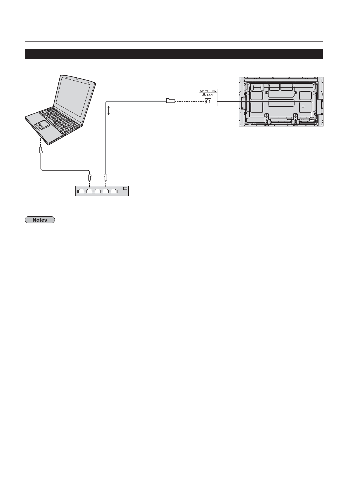
Example of Network Connection (Wired LAN)
MPUTE
LAN
not supplied
LAN
commercial
or br
• Make sure the broadband router or hub supports 100BASE-TX.
• Use a LAN cable between the twisted pair cable transmitter and the device that conforms to the following
nditions.
• It meets or exceeds CAT5e standards
• It is a shielded cable
• It is a straight cable
• It is a single wir
• When laying the cable(s), use an instrument such as a cable tester or cable analyzer and check whether the
able characteristics are CAT5e or above.
• Touching the LAN terminal with a statically charged hand (body) may cause damage due to its discharge.
Do not touch the LAN terminal or a metal part of the LAN cable.
• For instructions on how to connect, consult your network administrator
with a connector
Display (main unit, rear
1
Page 11
l
gg
LAN
.
.
.
.
.
.
p
)
.
.
f
l
y)
l
)
)
00G
d
cable
Connection
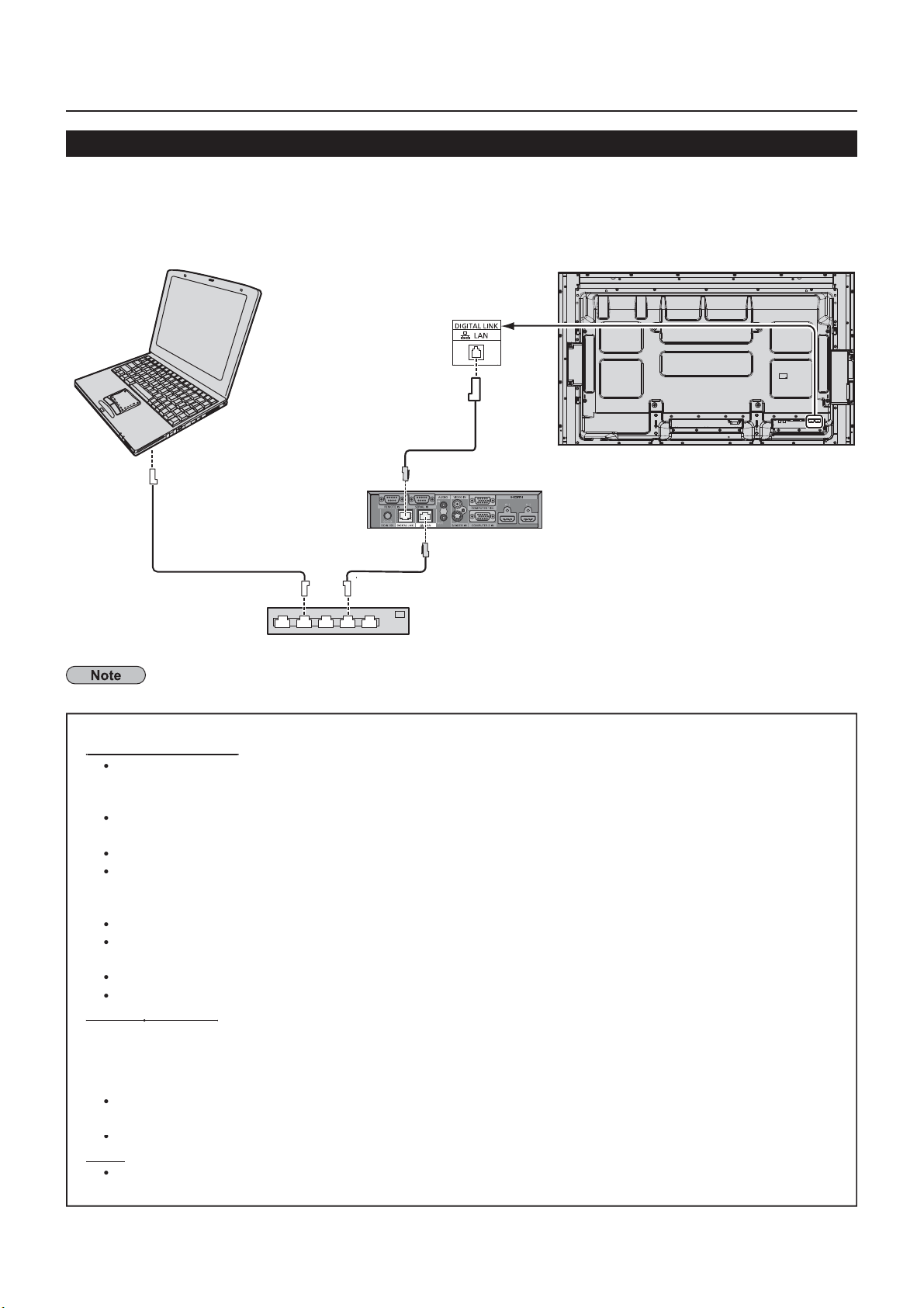
Example of Network Connection (DIGITAL LINK)
A twisted pair cable transmitter such as the Panasonic Digital Interface Box (ET-YFB100G) uses twisted pair cables
to transmit inputted video and audio signals, and these digital signals can be input to the Display via the DIGITAL
LINK terminal.
Network connections via DIGITAL LINK termina
Display (rear surface of the main bod
IGITAL LINK termina
commercial
Hub or broadband router
hen a Panasonic ET-YFB1
commercial
is use
on gure the settings in “Network Settings when using a DIGITAL LINK connection. (see pages 20 to 22)
recautions for use while connecting with a twisted pair cable transmitter
Ask the dealer or a quali ed technician to carry out the cable wiring work for DIGITAL LINK connections.
nsuf cient wiring work may cause the inability to apply the cable transmission characteristics and cropped
or fuzzy images and sounds.
The transmission distance between the twisted pair cable transmitter and the device is up to 100 meters.
xceeding this distance can cause cropped images or sounds, as well as
Do not use a hub between the twisted pair cable transmitter and the Display
When connecting to the Display using the twisted pair cable transmitter (receiver) of other maker, do not
use another twisted pair cable transmitter between the twisted pair cable transmitter of other maker and
this device. The images and sounds may be interrupted or become unstable
If possible, lay the cable so that it is extended and not coiled in order to minimize both external and internal noise
Lay out cables of the twist pair cable transmitter and this product away from other cables, especially from
the power supply cable
hen laying multiple cables, keep them as close together as possible running parallelly and not bundled
After laying the cable(s), make sure that the signal quality in “DIGITAL LINK status” is -12 dB or below
communication errors.
Use a LAN cable between the twisted pair cable transmitter and the device that conforms to the following
conditions.
It meets or exceeds CAT5e standards
It is a shielded cable (with a connector
When laying the cable(s), use an instrument such as a cable tester or cable analyzer and check whether the cable
haracteristics are CAT5e or above. When using a relay connector along the path, also include this in the measurements
Do not pull cables hard. Also avoid forcefully bending or folding them
ther
This device is compatible with our Digital Interface Box (ET-YFB100G). For the twisted pair cable transmitter
the other maker, see the website: http://panasonic.net/prodisplays/support/digitallink.htm
o
It is a straight cable
It is a solid
11
Page 12
Network Settings
ess
]
g
ake the various settings to use the network function.
or network settings, contact your network administrator.
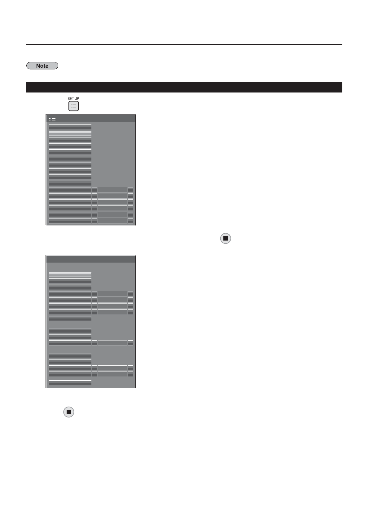
Displaying the Network Settings menu
Press
Setup
MULTI PIP Settings
Network Settings
Memory Viewer Settings
ECO Mode settings
Function Button Settings
On/Off Timer Settings
Day/Time Settings
Component/RGB-in select RGB
Monitor Out
No activity power off
Menu Display Duration
OSD Brightness
OSD Language
to display [Setup] menu.
Signal
Screensaver
Input label
Off
Disable
30 S
5
English (UK)
Starting up the network
It takes some time for the network to start up just after the
splay power is turned on.
Durin
that time, “Network Settings” in the “Setup” menu is
rayed out and cannot be set.
Select [Network Settings] with the and press
The [Network Settings] menu appears.
Network Settings
Network
Wired LAN
Wireless LAN
Name Change
Control I/F Select RS-232C
WEB Control
AMX D.D.
Crestron Connected™
Network Status
Panasonic APPLICATION
Password
Multi-Live
Live mode Cut In Off
DIGITAL LINK
DIGITAL LINK status
Digital Interface Box
DIGITAL LINK mode Auto
Extron XTP
Reset
On
Off
Off
Off
button.
Press to select the item and set with .
r
12
to display sub menu.
Page 13
3
Network Settin
gs
LAN
.
.
Off
ill
d.
s
g)
.
k
)
.
y
)
.
)
.
.
g.
A
.
168.10.100
0
y
1
b
)
.
.
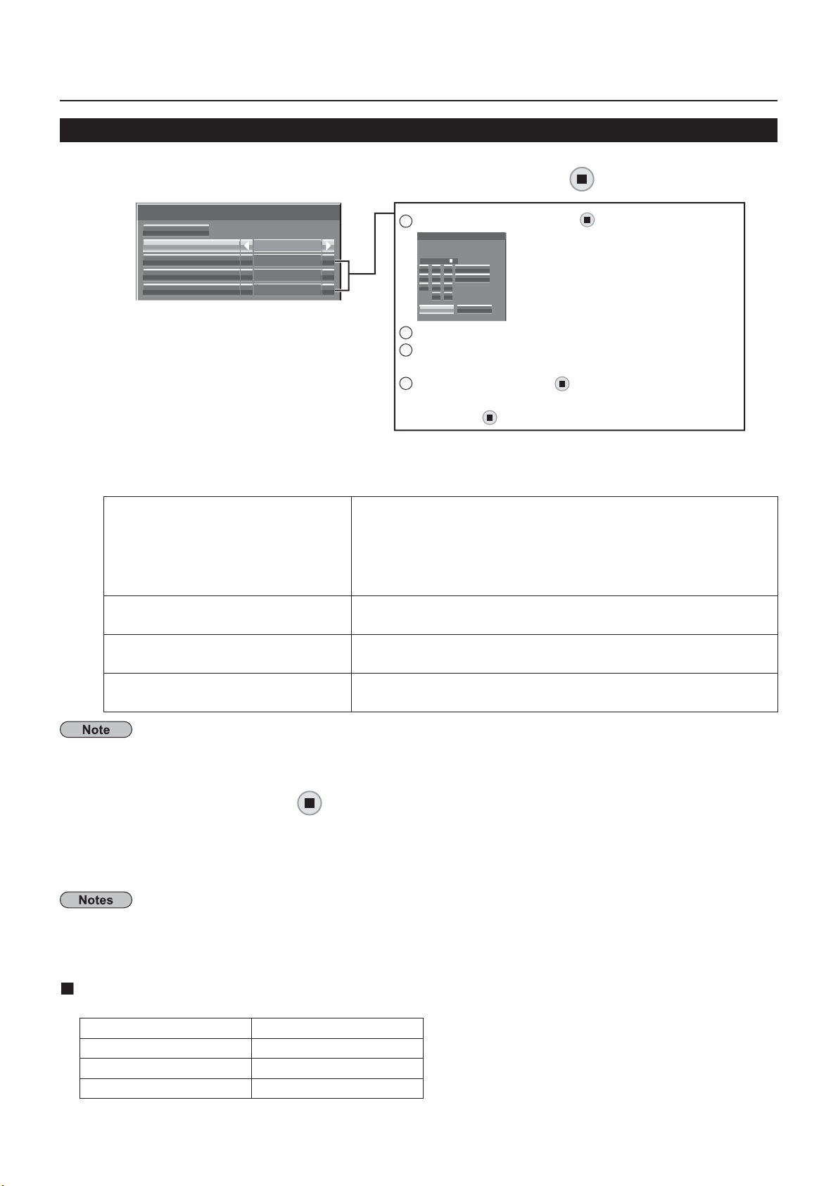
Wired LAN
ou can make detailed wired
settings
Select [Wired LAN] in [Network Settings] menu and press
Wired LAN
DHCP
IP address
Subnet mask
Gateway
Set [DHCP]
When [
HCP
DHCP client function)
Save
Off
192.168. 10.100
255.255.255. 0
192.168. 0. 1
] is selected, IP address and other settings can be set manually.
1
Select the item and press
IP address
000.192.168.010
1 2 3
4 5 6
7 8 9
2
Delete the current numbers. ([Delete] or [All delete]
3
Enter numbers and dots using numeric keypad on
All delete
Delete
0 .
Ok Cancel
the screen.
4
Select [Ok] and press button
To cancel changing the address, select [Cancel]
nd press button
n: If a DHCP server exists in the network to which the display
s connected, the IP address w
If a DHCP server does not exist in the network to which the
display is connected, additionally set [IP address], [Subnet
mask] and [Gateway].
button.
utton.
automatically be acquire
addres
Display of IP address and settin
Subnet mas
Displaying and setting the subnet mask
Gatewa
Display of gateway address and setting
Enter the IP address if DHCP server is not used
not using a DHCP server, enter the subnet mask
Enter the gateway address if DHCP server is not used
If [DHCP] is set to [On], the IP address and other items are not displayed. Check the [Network Status] page for the
urrent IP address and other items. (See page 20
Select [Save] and press
ave the current network settings
utton
If message indicating a duplicate IP address is displayed in [Network Status] (see page 20), check the same
IP address is not used within the same network.
Before using the DHCP server, make sure the DHCP server is already functionin
•
For details of IP address, subnet mask, and gateway, ask the network administrator.•
wired LAN and wireless LAN cannot be used in the same segment
•
Default wired LAN settings
The following settings are set before the Display leaves the factory.
DHCP
IP address
ubnet mask 255.255.255.
Gatewa
ff
.
192.168.10.
1
Page 14
Network Settin
gs
)
]
.
S
.
l
s
)
address
k
)
.
8
l
.
y
t
y
y
)
l
eless LAN
.
.
)
butto
.
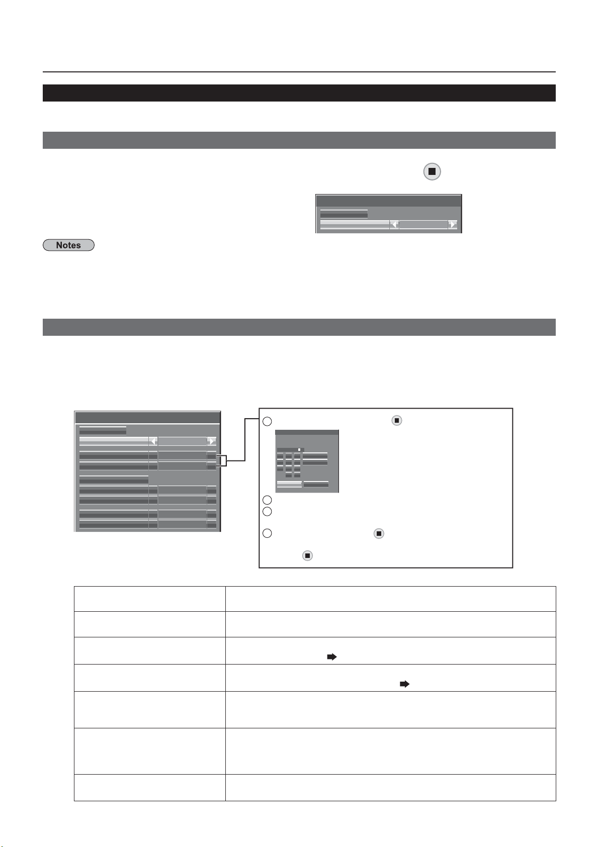
Wireless LAN
ou can make detailed wireless LAN settings. (You cannot select AD HOC mode with this display.
Setting network number
Select [Wireless LAN] in [Network Settings] menu and press
Select the number to be connected for
Wireless LAN].
Off], [S-DIRECT], [M-DIRECT], [USER1]-[USER3
Selecting [Off] disables the wireless LAN
•
Wireless LAN
Save
Wireless LAN
button.
Off
etwork number: [S-DIRECT] is available only when connecting via wireless LAN with the application software •
the “Wireless Manager”. For details, refer to the operation manual of the “Wireless Manager”.
Displays that can be connected to [
•
-DIRECT] or [M-DIRECT] are up to 10
You can con gure more precise network settings, if you select [M-DIRECT] or [USER1] - [USER3] (user) for [Wireless LAN]
Con guration of Wireless LAN [M-DIRECT]
Even if there is no access point, you can still connect the Display to computer via the infrastructure. In addition, the
onnection with the iPad / iPhone / iPod touch is much easier.
or more information, see the website below.
ttp://panasonic.net/prodisplays/download/software/index.htm
Select [M-DIRECT] for [Wireless LAN].
Wireless LAN
Save
Wireless LAN
IP address
Subnet mask
SSID
Channel
Key
Wireless Network Standby
Wireless WEB Control
M-DIRECT
192.168. 10.100
255.255.255. 0
1
********
1
Select the item and press button
IP address
000.192.168.010
1 2 3
4 5 6
7 8 9
2
Delete the current numbers. ([Delete] or [All delete]
3
Enter numbers and dots using numeric keypad on
All delete
Delete
0 .
Ok Cancel
the screen.
4
Select [Ok] and press
n.
14
Press to go to the next item.
IP addres
Displaying and setting the IP address
Subnet mas
Displaying and setting the subnet mask
SSID
Channe
e
Wireless Network Standby
for TH-50LFC70U, TH-65LFC70U,
TH-80LFC70U, TH-50LFC70W,
TH-65LFC70W and TH-80LFC70W)
Wireless WEB Contro
button
Enter the IP
.
Enter the subnet mask
elect [M-DIRECT] in [Wireless LAN], then the SSID can be set.
ntering characters page 1
elect [M-DIRECT] in [Wireless LAN], then the Channel can be set
elect a channel for the access point ( page 8).
elect [M-DIRECT] in [Wireless LAN], then the Key can be se
etting a key for the access point. Input either 8 to 63 alphanumerics or
64 digit string in the hexadecimal format.
et to [On] when using wireless web control or command control to turn
the power off/on. When set to [On], power consumption in standb
higher than when set to [Off]. (This function is not supported b
TH-50LFC70E, TH-65LFC70E and TH-80LFC70E.
et to [On] when controlling the display from a web browser on a PC
nnected via wir
.
is
Page 15
5
.
Off
ge
8
ill
d.
.
)
k
)
y
)
)
g.
A wired LAN
LAN
.
Network Settin
gs
.
.
9
00
0
C
l
y
.
.
A
butto
)
3
Select [Save] and press
ave the current network settings
utton
Default settings of [M-DIRECT]
The following settings as [M-DIRECT] in the [Wireless LAN] are set before the Display leaves the factory.
IP address 1
2.168.12 .1
ubnet mask 255.255.255.
SSID M-DIRE
T + The last 4 digits of the Display ID
Channe
e
reless Network
Standby
The same string as the SSID
(for TH-50LFC70U, TH-65LFC70U,
TH-80LFC70U, TH-50LFC70W, TH-65LFC70W
and TH-80LFC70W)
Wireless WEB Control
The authentication method is WPA2-PSK, and the encryption method is AES. Both methods are xed
•
hen you need to change initial con guration of [M-DIRECT], please contact your network administrator
•
ake sure the initial Key is changed for safety.•
s the DHCP server is already functioning, select [ON] before connecting a computer.•
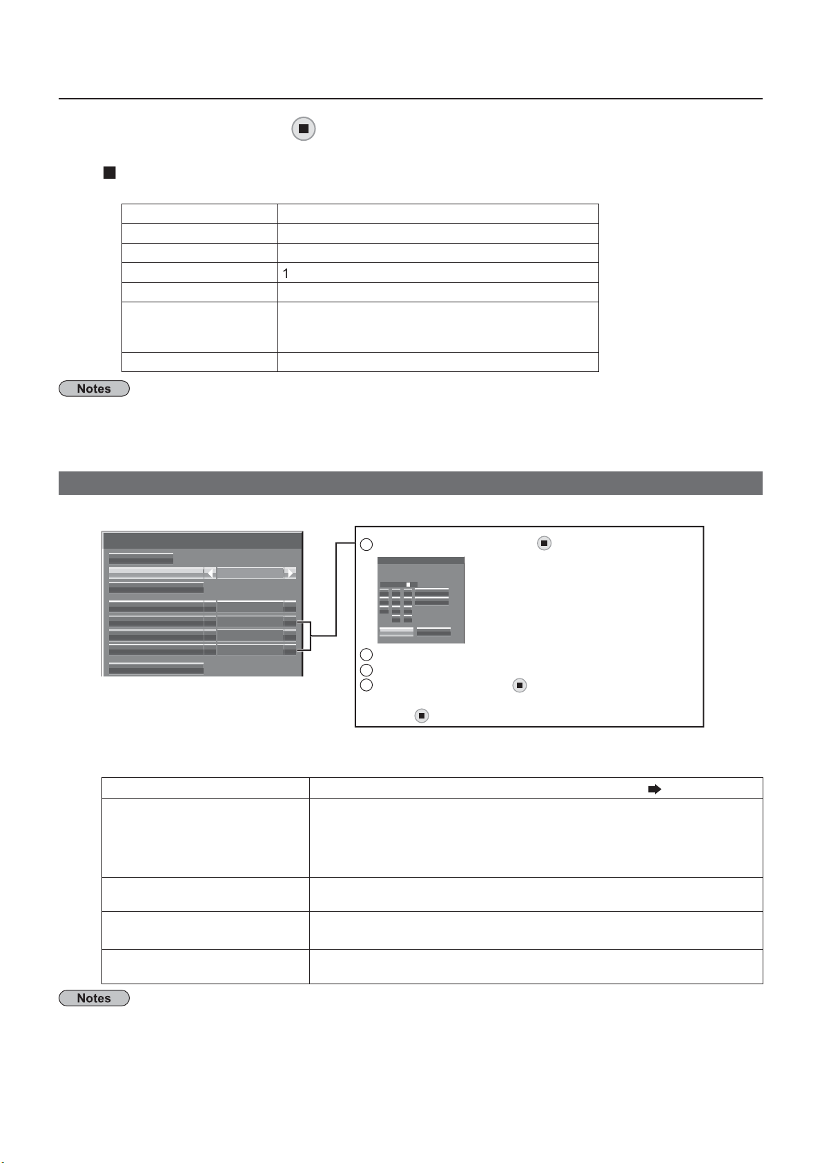
Con guration of Wireless LAN [USER1] - [USER3]
Select [USER1] – [USER3] for [Wireless LAN].
Wireless LAN
Save
Wireless LAN
Name Change
DHCP
IP address
Subnet mask
Gateway
SSID
USER1
Off
192.168.11.100
255.255.255. 0
192.168.11.1
Set [DHCP]
When [
Name Chan
HCP
DHCP client function)
IP address
Display of IP address and setting
Subnet mas
Displaying and setting the subnet mask
atewa
Display of gateway address and setting
] is selected, IP address and other settings can be set manually.
1
Select the item and press
IP address
000.192.168.11
All delete
1 2 3
4 5 6
7 8 9
2
Delete the current numbers. ([Delete] or [All delete]
3
4
Select [Ok] and press button.
Delete
0 .
Ok Cancel
n.
button.
You can change the user name.
ntering characters page 1
On: If a DHCP server exists in the network to which the display is
connected, the IP address w
automatically be acquire
If a DHCP server does not exist in the network to which the
display is connected, additionally set [IP address], [Subnet mask]
nd [Gateway]
Enter the IP address if DHCP server is not used.
If not using a DHCP server, enter the subnet mask.
Enter the gateway address if DHCP server is not used.
•
•
f [DHCP] is set to [On], the IP address and other items are not displayed. Check the [Network Status] page for •
the current IP address and other items. (See page 20
Before using the DHCP server, make sure the DHCP server is already functionin
For details of IP address, subnet mask, and gateway, ask the network administrator.•
and wireless
cannot be used in the same segment
1
Page 16
Network Settin
gs
D
.
.
A
n
S
/
e
ress to go to the next item.
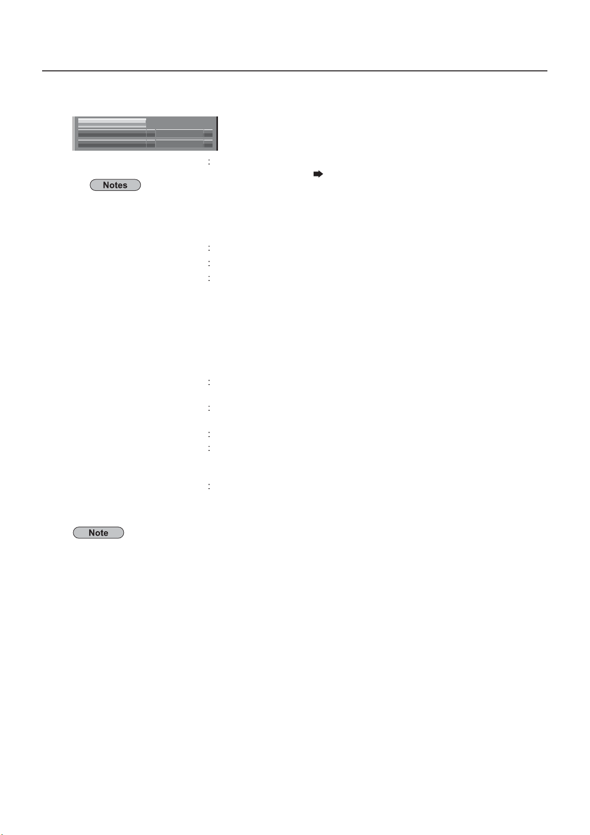
Make the settings related to the wireless connection between the Display and the network.
SSID
Authentication
Encryption
Open
None
SSI
SID has to be entered in alphanumeric letters
•
ou cannot set “any” or “ANY” for SSID
•
uthentication
Ope
hared
WPA-PSK
WPA2-P
WPA-EAP
WPA-EAP
WPA2-EAP
ncryption
Non
AES
K
-
nter the SSID registered at the access point.
Entering characters page 18
Set the user authentication method used by the network to be connected.
elect when the access point authentication method is OpenSystem.
elect when the access point authentication method is Shared Key.
Select the encryption method to be used for communication between the
splay and the network.
elect when transmit without encryption. It is selectable only when
Authentication] is [Open] or [Shared].
Select when Encryption is WEP.
elect when Encryption is TKIP.
electable when [Authentication] is either [WPA-PSK], [WPA2-PSK],
WPA-EAP], [WPA2-EAP].
Select when Encryption is AES.
electable when [Authentication] is either [WPA-PSK], [WPA2-PSK],
WPA-EAP], [WPA2-EAP].
Important video/audio data is protected because AES encryption programming takes place in advance for
all network numbers, even if [Encryption] is set to [None].
16
Page 17
Network Settin
gs
d:
y
y.
.
:
].
)
:
).
.
.
.
.
y
on
n
00
0
y
1
Press to go to the next item.
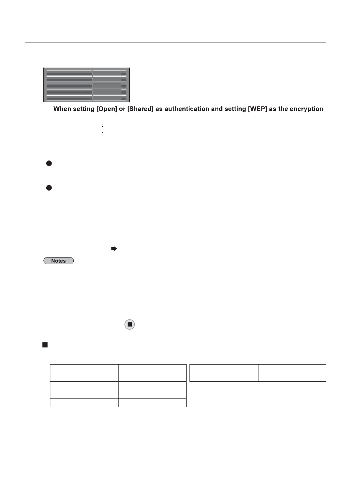
In addition, further perform the following setting depending on [Authentication] and [Encryption] settings.
Default Key
Key 1
Key 2
Key 3
Key 4
etho
Default Ke
Key1 – 4
When using [WPA-PSK] or [WPA2-PSK] :
When the authentication method is [WPA-EAP/WPA2-EAP], [WPA-EAP], [WPA2-EAP]
et [EAP], [User name], and [Password
EAP
ser name
assword:
ntering characters page 18
1
*******
*******
*******
*******
et 1 – 4 numerals for the default ke
et a WEP key to the key number selected with [Default Key]
Either the 64-bit or 128-bit WEP key can be set. For the 64-bit key, input ve
alphanumerics (or a 10-digit string for the hexadecimal format) for the 128-bit key,
input 13 alphanumerics (or a 26-digit string for the hexadecimal format).
et a key.
Input either 8 to 63 alphanumerics or a 64 digit string in the hexadecimal format.
Select the EAP setup in the RADIUS server. Types of EAP that can be selected are as
follows.
EAP (MS-CHAPv2), PEAP (GTC), EAP-TTLS (MD5),
EAP-TTLS (MS-CHAPv2), EAP-FAST(MS-CHAPv2), EAP-FAST(GTC
nput a user name used for authentication (excluding spaces)(maximum 64 characters).
nput a password used for authentication (maximum 64 characters
5
If you are unable to connect to the wireless LAN through the access point, contact the manufacturer of
the access point
When using EAP, the display needs to be set according to the setting of the RADIUS server. Check with
the network administrator for the setting of the RADIUS server.
When using an EAP together with an access point with invalid SSID broadcast, select WAP-EAP or
WAP2-EAP for the authentication method even if the authentication method of the access point is WPA-
AP/WPA2-EAP
Select [Save] and press
ave the current network settings
utton
Default settings of [USER1] - [USER3]
The following settings as [USER1] - [USER3] in the [Wireless LAN] are set before the Display leaves the
actory.
ID Panasonic Displa
DHCP Off
IP address 192.168.11.1
ubnet mask 255.255.255.
Gatewa
192.168.11.
Authenticati
ncryption
Ope
one
17
Page 18
8
Network Settin
gs
.
t
]
.
Name Change
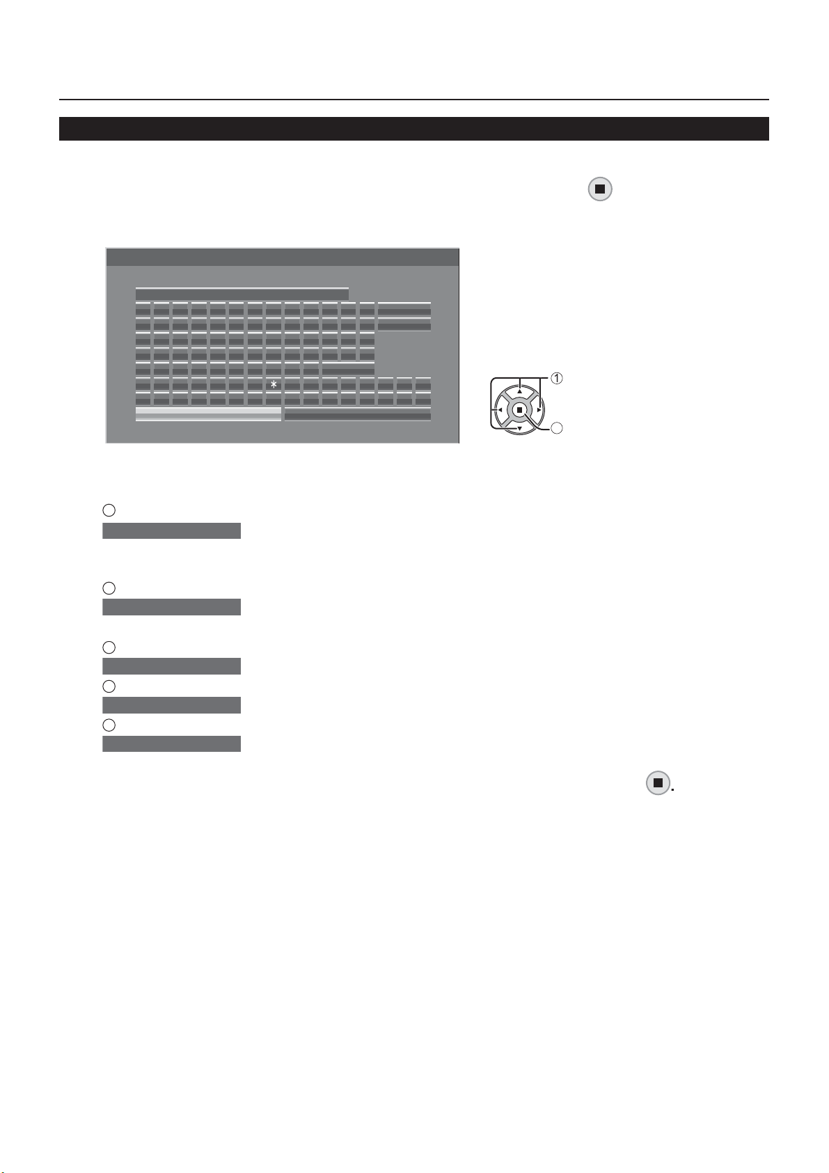
ou can change the Display name to be displayed on the network.
Select [Name Change] in [Network Settings] menu and press
The keyboard is displayed.
p to 8 characters can be entered for the Display name.
Name Change
Name0000
ABCDEFGH I JKLM
NOPQRSTUVWXYZ
abcde fgh i j k lm
nopqrs tuvwxyz
0123456789
!”#$%&’ +–/=?
_` | ~<> ( ) [ ] { } ,
Ok
Space
Cancel
All delete
Delete
@\ ˆ
.;:
Entering characters
To enter text, select characters in the on-screen keyboard
xample: Specifying “LCD 01”
1
Select “All delete”.
Name0000
All text is deleted.
To delete individual characters, select “Delete”.
2
Select “L”.
L
epeat this process to enter the next character.
3
Select “C” and “D”.
LCD
4
Select “Space”.
LCD
5
Select “0” and “1”.
LCD 01
utton
select
se
When you nished entering the Display name, select [Ok] and press
To cancel saving the Display name, select [Cancel].
1
Page 19

9
Network Settin
gs
.
).
y).
G
S
.
ebsite
y
®
Express
V
®
®
Server Edition
.
®
Express”, refer to the Crestron Electronics, Inc. website (Provided only in
)
Control I/F Select
elect whether to control via RS-232C of the Display's SERIAL terminal or with the DIGITAL LINK/LAN terminal.
If “DIGITAL LINK/LAN” is selected, the power indicator lights orange when the power is turned off with the remote
control (standb
RS-232C: Controls via RS-232C using the Display's SERIAL terminal.
DI
ITAL LINK/LAN: Controls via LAN using the LAN terminal of the Display or twisted pair cable transmitter or via
R
-232C using the SERIAL (RS-232C) terminal of twisted pair cable transmitter.
Select [Control I/F Select] in [Network Settings] menu and press
button.
Select [RS-232C] or [DIGITAL LINK/LAN]
If “RS-232C” is selected, HDMI communication via twisted pair cable transmitter becomes possible.
For the case of “DIGITAL LINK/LAN”, see “DIGITAL LINK mode” (see page 22
WEB Control
et to [On] when controlling the display from a web browser on a PC connected via wired LAN.
Select [WEB Control] in [Network Settings] menu and press
button.
Select [On] or [Off]
hen using [WEB Control] wirelessly, enable wireless LAN in [Wireless LAN] in the [Network Settings] menu, and
et [Wireless WEB Control] to [On]. (See pages 14 to 15
AMX D.D.
This function allows the Display to be detected by AMX Device Discovery. For more details, visit the following
w
.
ttp://www.amx.com/
Crestron Connected™
hen this function is set to on, the Display can be monitored or controlled via the network using equipment and
application software of Crestron Electronics, Inc.
This Displa
Fusion R
restron Connected™] is a function to connect to a system developed by Crestron Electronics, Inc. which
anages and controls multiple system devices connected to the network
• For details of “Crestron Connected™”, refer to the Crestron Electronics, Inc. website (Provided only in English).
ttp://www.crestron.com/
For the download of “RoomView
English).
ttp://www.crestron.com/getroomview
supports the following application software from Crestron Electronics, Inc.
mView
mView
1
Page 20
0
Network Settin
gs
.
.
.
.
.
.
s.
.
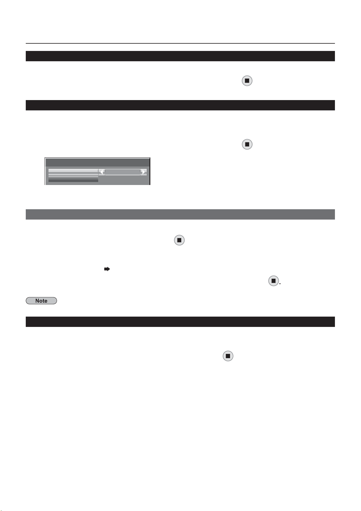
Network Status
Displays the current network status
Select [Network Status] in [Network Settings] menu and press button.
The Display information, settings of wired LAN and wireless LAN are displayed.
Password
et to [On] to perform password check when connecting with the Display using “Wireless Manager”
y controlling connection with password setting, it is possible to prevent an external device from accidentally
onnecting and interrupting images, etc
Select [Password] in [Network Settings] menu and press
Password
Password
Password Change
Off
Select [On] or [Off] for [Password]
Password Change
Password can be registered or changed. No password is set in the default setting
Select [Password Change] and press
The keyboard is displayed.
p to 8 characters can be entered for the password.
ntering characters page 18
utton.
When you nished entering the password, select [Ok] and press
To cancel saving the password, select [Cancel].
It is recommended to change password on a regular basis for keeping it private
button.
Multi-Live
witch to the MULTI-LIVE mode when using the “Wireless Manager”. See the “Wireless Manager” operation
nual for detail
Select [Multi-Live] in [Network Settings] menu and press
utton
2
Page 21
.
d p
.
.
N
d
d
.
12
8
above
y
LAN
Network Settin
gs
.
.
Live mode Cut In
et this [ON] to allow interrupt of the Live mode by other users while the Live mode is active (sending image) by the
Wireless Manager”. For details, refer to “Wireless Manager” operating manual.
Select [Live mode Cut In] in [Network Settings] menu and press
Select [On] or [Off]
utton
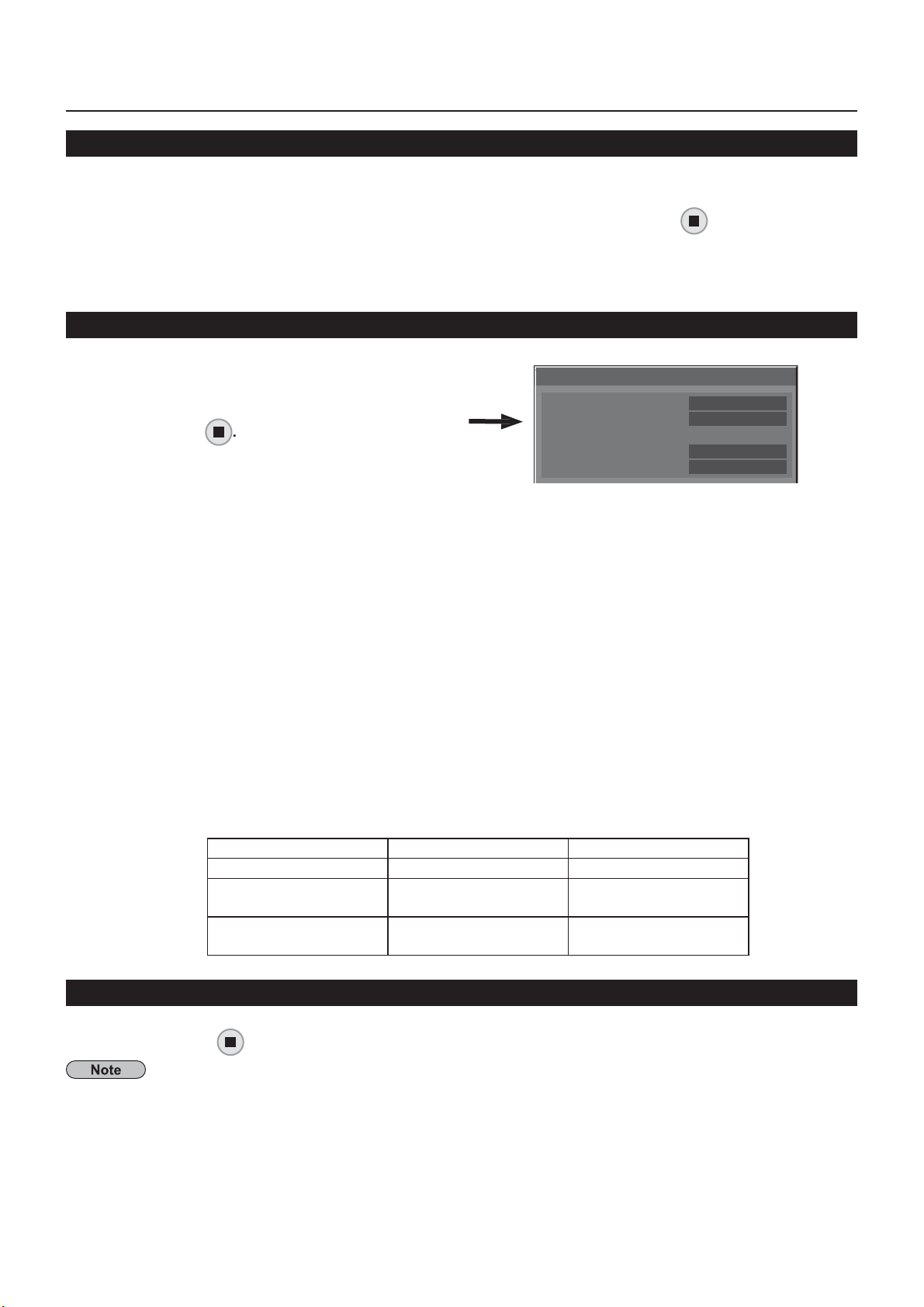
DIGITAL LINK status
Display the DIGITAL LINK connection environment
DIGITAL LINK status
Select “DIGITAL LINK status” in [Network Settings]
menu, an
LINK status : Either “No link”, “DIGITAL LINK”, or “Ethernet” will be displayed
DMI status : Either “No HDMI”, “HDMI ON”, or “HDCP ON” will be displayed.
ignal quality : It is the quanti ed minimum and maximum numbers of errors that have occurred. The display
ress
o link : No LAN connection, etc
IGITAL LINK : Connected to the DIGITAL LINK device by LA
Ethernet : The PC is connected to the DIGITAL LINK terminal of this product and is
LAN connecte
o HDMI : DIGITAL LINK not connecte
HDMI ON : DIGITAL LINK connected
HDCP ON : A signal with an HDCP is owing with a DIGITAL LINK connection.
olors are red, yellow, or green, depending on the number
The number is represented by yellow or red if the LAN cable is disconnected or the cable is
not shielded. This signal quality shows gures between the twisted pair cable transmitter that is
onnected and the display.
Signal Quality Display Colors Reception Status
-
dB or below
-11 to -
-7dB or
dB Yellow Part of the received
reen The reception is normal
LINK status
HDMI status
Signal Quality
Minimum
Maximum
data is corrupted
ere are reception
dif culties
No Link
No HDMI
-XX dB
-YY dB
Digital Interface Box
A switch will be made to the Set up Digital Interface Box menu when “Digital Interface Box” in [Network Settings]
enu is selected and is pressed.
This function can onl
to a
terminal and its power is on.
be selected when the Digital Interface Box (ET-YFB100G) made by our company is connected
21
Page 22
.
.
Network Settin
gs
LAN
LAN
l.
A
/
.
.
.
DIGITAL LINK mode
ou can switch the setting of DIGITAL LINK/LAN terminal.
: Enables
uto (LAN): Enables automatic selection between LAN communication via the Display's LAN terminal and HDMI
DIGITAL LINK (LAN): Enables HDMI/LAN communication via the twisted pair cable transmitter
DIGITAL LINK (RS-232C): Enables HDMI/RS-232C communication via the twisted pair cable transmitter.
To use the control methods shown in pages 24 to 34, select “LAN”, “Auto (LAN)” or “DIGITAL LINK (LAN)”.•
Power consumption during standby is slightly larger if you set to any other setting than “LAN”
•
Extron XTP
To carry out connection settings with XTP Transmitter made by Extron. Visit the following website for details.
ttp://www.extron.com
Reset
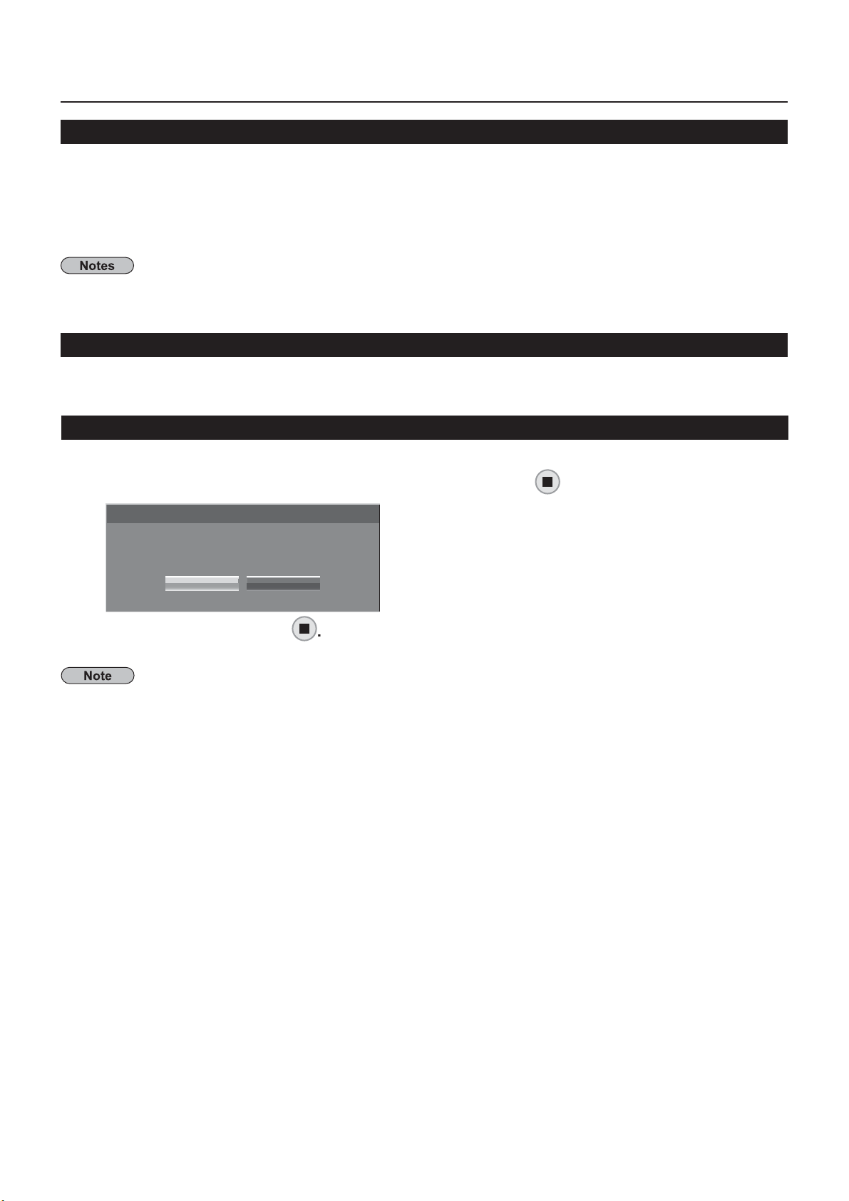
You can reset the network setting to the factory default of the Display
communication via the Display's
LAN communication via the twisted pair cable transmitter
termina
Select [Reset] in [Network Settings] menu and press
Network Settings
Reset
Yes No
button.
Select [Yes] and press
It takes some time to restart network while the network settings are initialized
During that time, “Network Settings” in the “Setup” menu is grayed out and cannot be set.
22
Page 23
3
Connecting with Wired LAN
)
01
0
y
.
168.11.101
0
y
1
y
.
N
To use the network function, make the necessary settings in [Network Settings] and be sure to set LAN to enabled
in [Control I/F Select] and [DIGITAL LINK mode]. (See page 20
Computer operation
onnection can be made with wired LAN. However, con rm to your system administrator on network settings
before changing any settings.
urn on the computer.
ake the network setting according to your system administrator.
If the Display settings are the default settings (ee page13), the computer can be used with the following
network settings.
IP address 192.168.10.1
ubnet mask 255.255.255.
atewa
192.168.10.1
Connecting with Wireless LA
Computer operation
ake the network setting according to your system administrator.
If you select [M-DIRECT] for [Wireless LAN] in the [Network Settings] menu, the IP address will
automatically be acquired
If you select default settings of [USER1] - [USER3] for [Wireless LAN] in the [Network Settings] menu (see
page 17), then the computer can be used with the following network settings.
IP address
ubnet mask 255.255.255.
atewa
Connect to the wireless network that has the same [SSID] set with the Display.
When you select default settings of [M-DIRECT] for [Wireless LAN] in the [Network Settings] menu, the
ID is [M-DIRECT + The last 4 digits of the Display ID].
When
the SSID is [Panasonic Display].
ou select default settings of [USER1] - [USER3] for [Wireless LAN] in the [Network Settings] menu,
If you use any wireless utility other than Windows [Wireless Network Connection], follow its operation
rocedure for connection
If you use the access point, con gure the Display and each network setting of the computer following the
instruction of the network administrator.
.
192.168.11.
2
Page 24
sing Web Browse
r
.
.
.
Avoid
A
.
.
Accessing from the Web browser
Activate the Web browser in the personal computer.
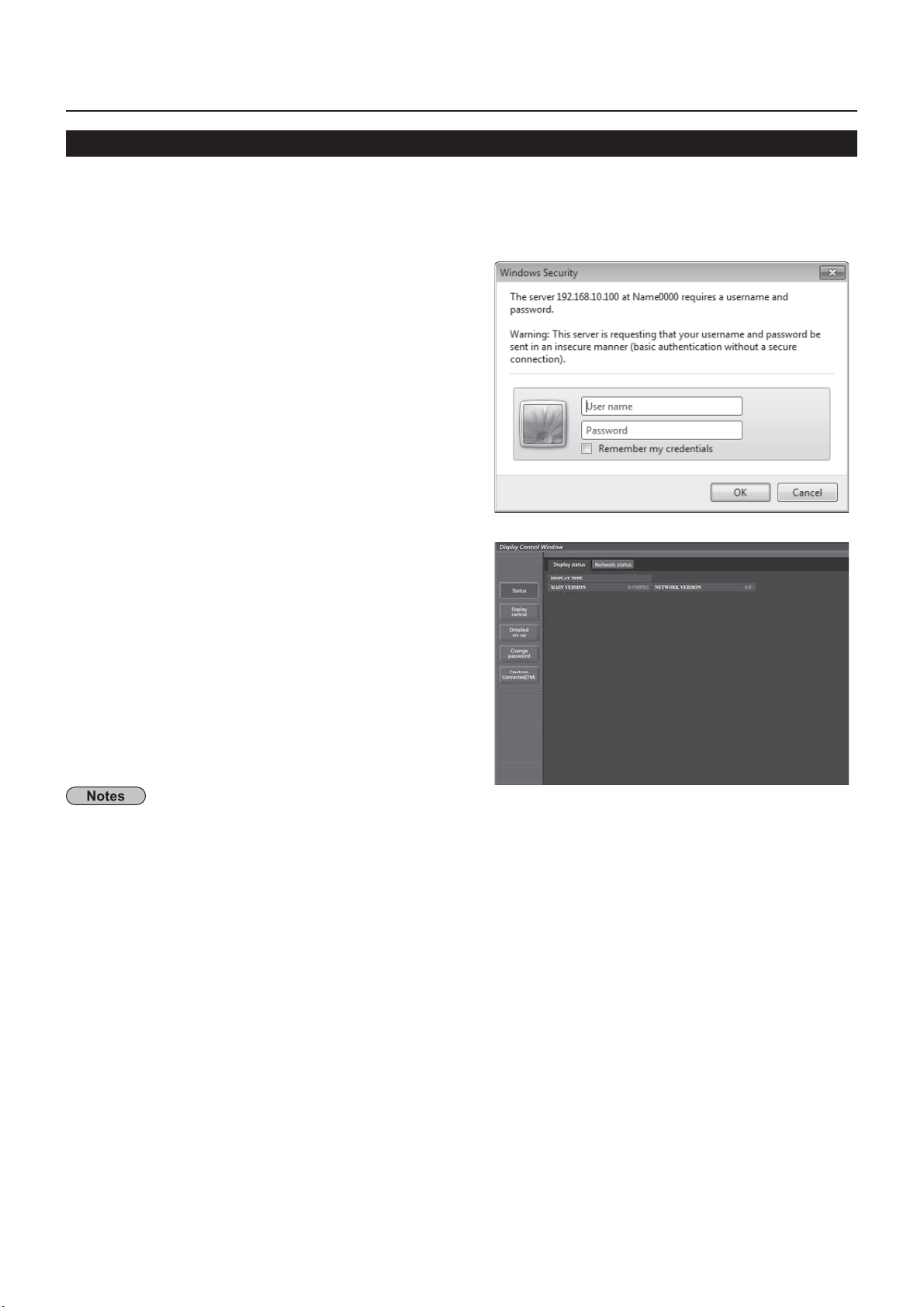
Enter the IP address set by the Display into the URL input eld of the Web browser.
Enter your “User name” and “Password”
The factory default settings are user1 (user
privileges) or admin1 (administrator privileges) for the
user name and panasonic for the password
Click [OK] to display the Display status
TH-50LFC70
Display status” page is displayed
activating two or more Web browser simultaneously to work out setting or control actions.•
hange the password rst of all.•
dministrator privileges enable the use of all functions. User privileges enable the use of only “Display status”, •
Network status”, “Basic control”, “Advanced control”, and “Change password”
f the password is incorrectly entered three times in a row, the lock is set for several minutes
•
you want to control the Display using a Web browser, set [WEB Control] in [Network Settings] menu to [On].•
24
Page 25
Using Web Browse
r
.
.
y.
.
b
S
s
p
d
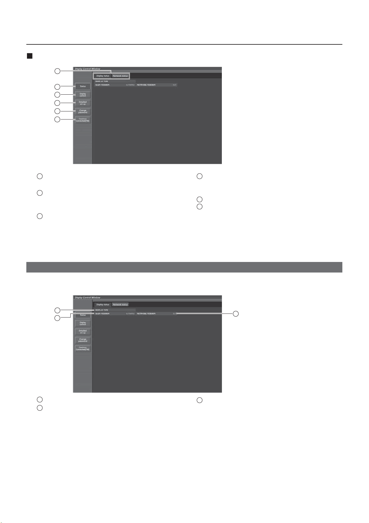
Description of each item
1
2
3
4
5
6
TH-50LFC70
1
Page ta
Click these to switch pages.
2
tatu
lick this item, and the status of the Display is
displayed.
3
Display control
4
Detailed set u
lick this item to display the advanced settings
age.
5
Change passwor
6
lick this item to display the Crestron Connected™
peration page.
lick this item to display the Display control page.
Display status page
lick [Status], then [Display status] to display the Status information page
This page displays the Display statuses established for the items shown below
1
2
TH-50LFC70
3
1
Displays the type of Displa
2
Displays the rmware version of the Display main
Displays the rmware version of the network
3
nit.
25
Page 26
Using Web Browse
r
.
.
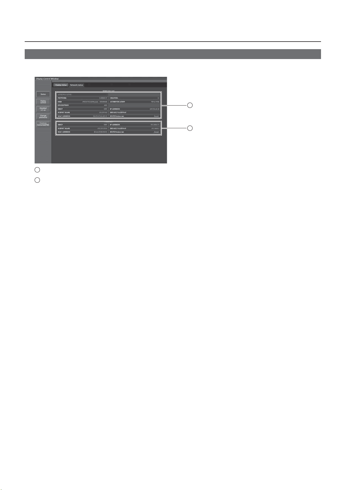
Network status page
lick [Status], then [Network status] to display the Status information page.
Displays the current con guration information of the network.
1
2
1
Displays the con guration details of wireless LAN
2
Displays the con guration details of wired LAN
26
Page 27
Using Web Browse
r
/Off
e
e
.
.
W
)
.
.
Af
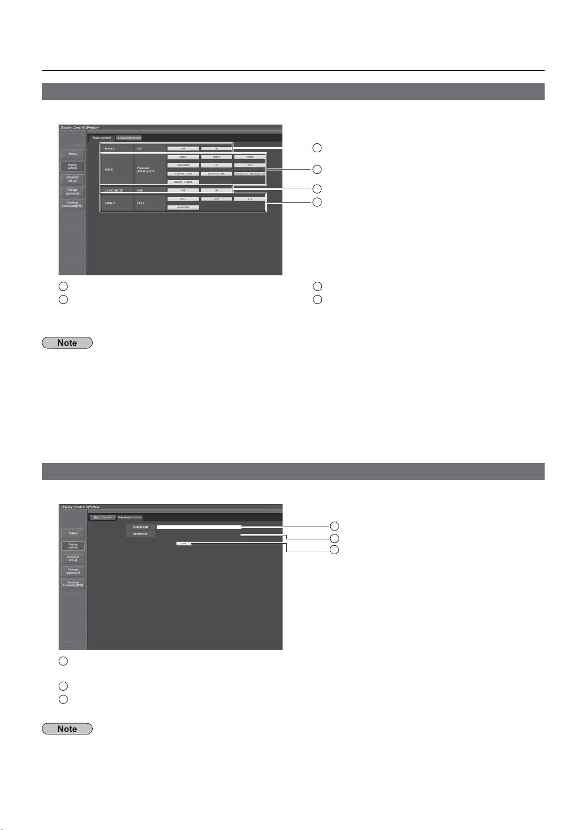
Basic control page
To move from another page, click [Display control], then [Basic control].
1
2
3
4
1
Power On
2
Use these to select the input signals
control
3
Operation of AV mut
4
Switches aspect mod
The following points will be different when connected wirelessly.
Switching to Miracast™ and MEMORY VIEWER input will not be possible
•
ontrol will not be possible with Crestron Connected™
•
H-50LFC70U, TH-65LFC70U, TH-80LFC70U,
H-50LFC70W, TH-65LFC70W, TH-80LFC70
• When [Wireless Network Standby] is off, operation for turning the power on/off will not be shown.
H-50LFC70E, TH-65LFC70E, TH-80LFC70E
•
Wireless Network Standby] function is not supported, and operation for turning the power on/off will not be shown.
Detail control page
lick [Display control], then [Advanced control] to display the Detail control page.
1
2
3
1
Enter a command. Use the same command used for the serial control.
refer to “Operating Instructions, Display Operations”
2
Response from the unit is displayed
3
Command is sent and run
ter the settings are changed, it may take a while till the display status is displayed.
27
Page 28
8
Using Web Browse
r
User
A
t
d
d
d
d
)
t
ccount
d
d
)
A
d
d
)
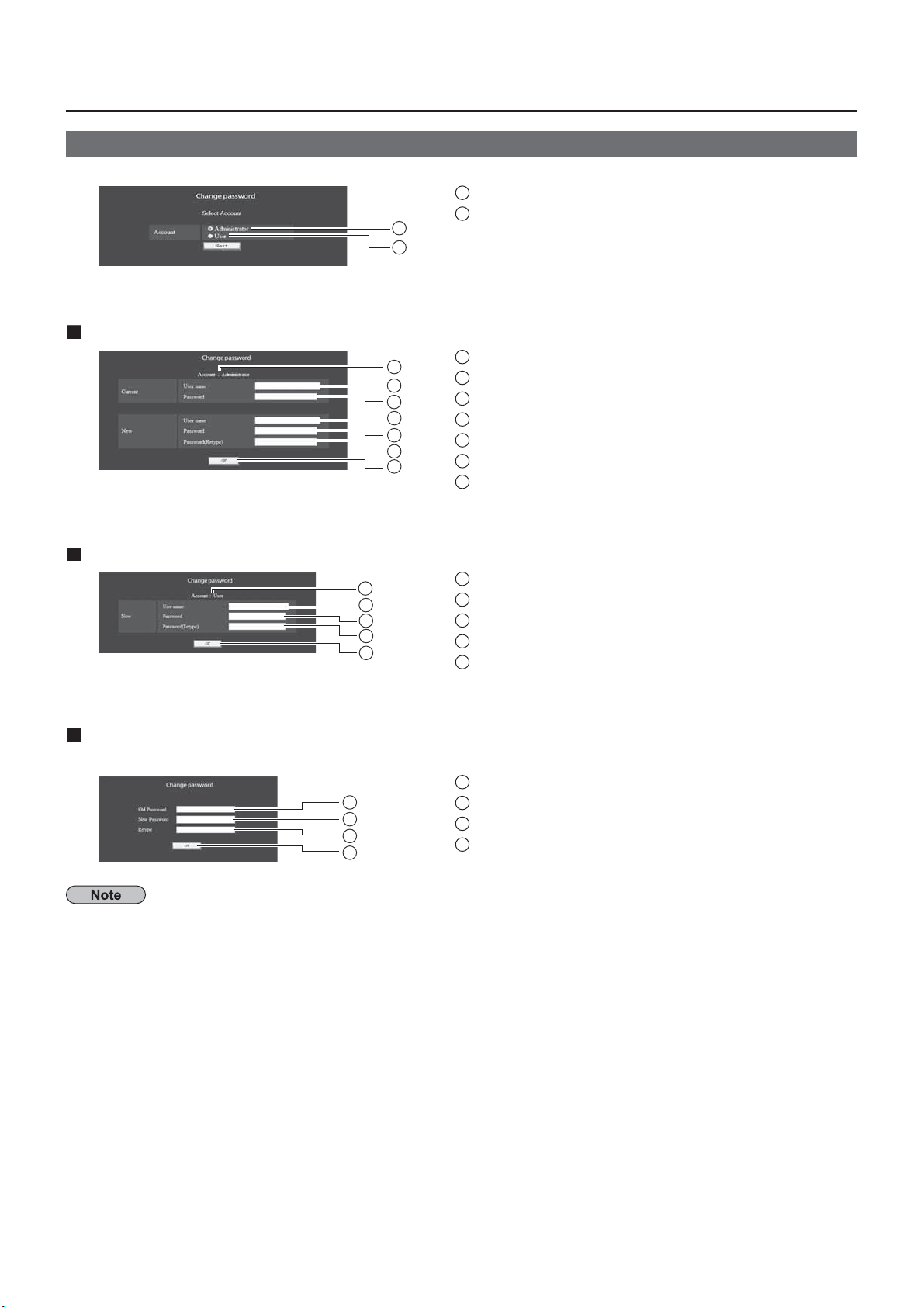
Change Password page
lick [Change password].
Administrator mode
1
Administrator
1
2
1
2
3
4
5
6
7
2
1
ccoun
2
Current user name input el
3
Current password input el
4
New user name input el
5
New password input el
6
New password input eld (re-enter for con rmation
7
Button for executing password change
ser accoun
1
1
2
3
4
5
A
2
New user name input el
3
New password input el
4
New password input eld (re-enter for con rmation
5
Button for executing password change
ser mode
user can change password only.
1
Current password input el
1
2
3
4
hen changing the administrator account, both “Current user name” and “Current password” are required.
2
New password input el
3
New password input eld (re-enter for con rmation
4
Button for executing password change
2
Page 29
9
Using Web Browse
r
.
.
k].
g
.
.
)
)
A
)
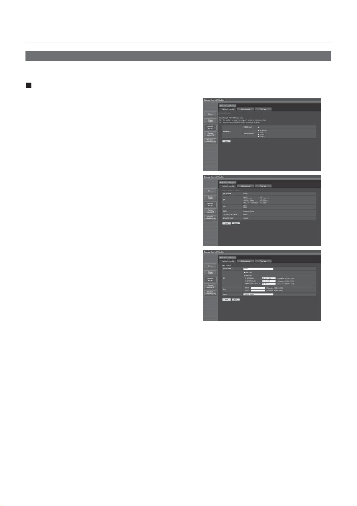
Network con g page
ou can make detail network settings on Display, when connecting without the administrator authority or when
onnecting with Wireless LAN
LAN settings
Click [Detailed set up] in the menu.
1
Select the items to change and click [Next].
The settings window appears, showing the current
ettings.
To change the LAN settings, click [Change]
•
o return to the previous window, click [Bac
•
Complete the detailed settings and click
Next].
When [Next] is clicked, the next page appears, enablin
ou to complete the detailed settings as desired
ettings performed here are the same as the settings
erformed with the [Network Settings] menu of the
Display
ired LAN (See page 13
•
ireless LAN (See page 14
•
fter all required items have been entered, a con rmation
window appears.
Wireless LAN screen
2
Page 30
Using Web Browse
r
.
)
.
g
d
d
y.
Click [Submit]
The settings will be registered.
Wireless LAN screen)
Making the above settings effective (Only for wireless LAN
Select [Wireless LAN] in [Network Settings] menu of the Display, and select the network set in this page.
mportant video/audio data is protected because AES encryption processing takes place.•
hanging the setting of LAN while connected with LAN might disconnect the connection
•
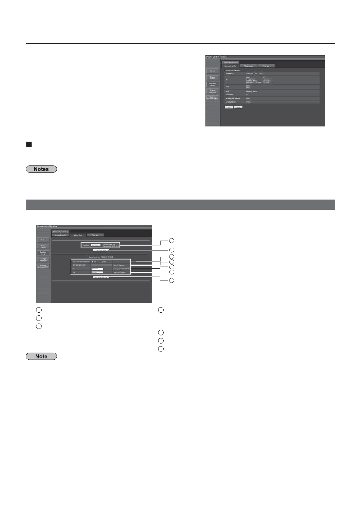
Adjust clock page
lick [Detailed set up], then [Adjust clock] to display the Adjust clock page.
1
2
3
4
5
6
7
1
Time zone selection
2
Button to update time zone settin
3
Turn this [ON] to set the date and
time automatically.
4
When setting the date and time automatically, input the IP
address or name of the NTP server. (When inputting the server
ame, the DNS server must be set.)
5
New date el
6
New time el
7
Button to update time and date settings
If the time becomes incorrect immediately after setting the correct time, contact the dealer where you bought the
Displa
Page 31
Using Web Browse
r
.
.
l
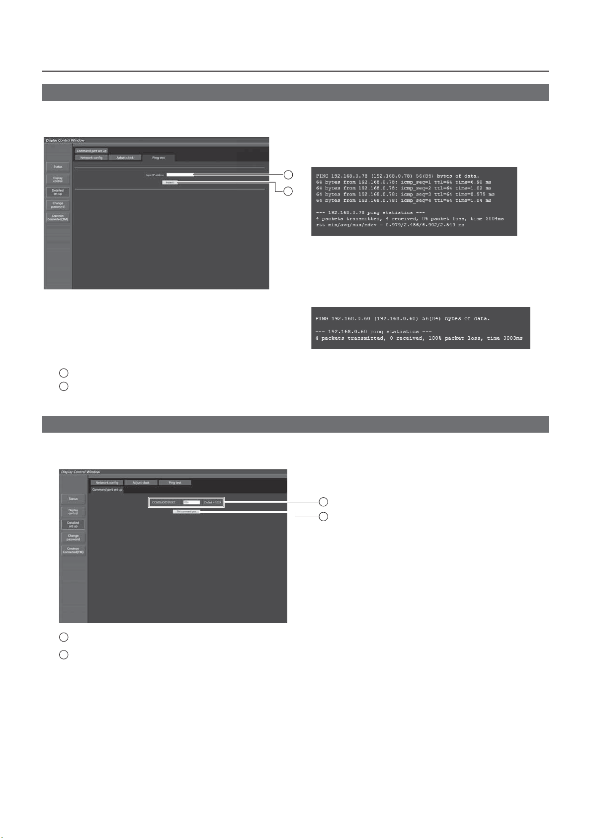
Ping test page
This page makes it possible to check whether the network is connected to the DNS server, etc.
lick [Detailed set up], then [Ping test] to display the Ping test page.
isplay which appears when the connection
was successful
1
2
splay which appears when the connection
failed.
1
Enter the IP address of the server to be tested.
2
Button for conducting the test.
Command port set up page
et the port number to be used with command control
lick [Detailed set up] [Command port set up].
1
Input the port number to be used with command contro
2
Setting update button
1
2
1
Page 32
2
e
.
.
e
ff
y
s
.
k
S
.
d
f C
.
s
g.
.
.
it
ge
.
.
(
)
sing Web Browser Control
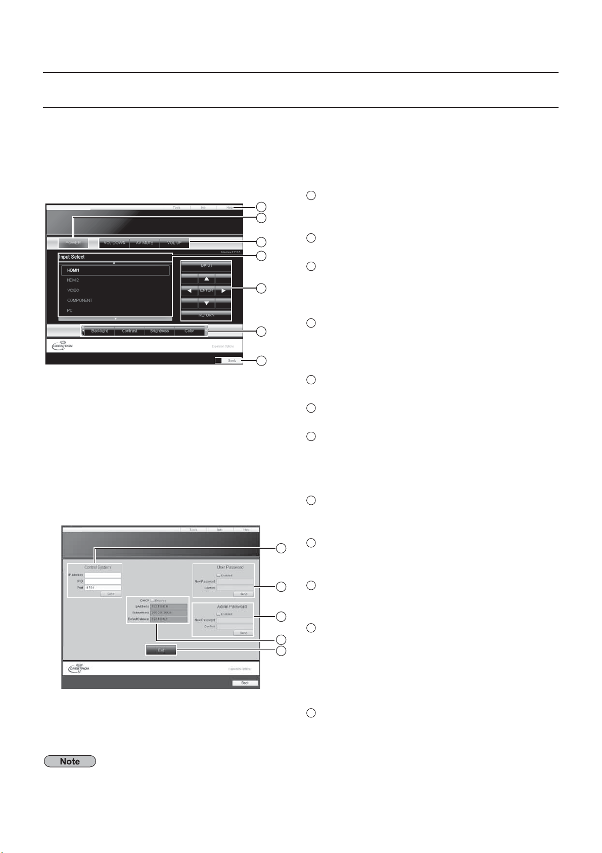
Crestron Connected™ pag
ou can monitor or control the Display using Crestron Connected™
hen you click [Crestron Connected™], the Crestron Connected™ operation page is displayed
If Adobe Flash Player is not installed in your computer, or if the browser does not support Flash, this page does not
appear. In this case, return to the previous page by clicking [Back] in the operation page.
Operation pag
Panasonic LCD Display
1
Tools, Info, Help
1
2
3
4
5
Switches the pages for tools, information, help
sing the tab.
2
POWER
witches between on and off of the power.
3
VOL DOWN, AV MUTE, VOL UP
ets the volume, AV mute. When the power of the
Display is turned o
, VOL DOWN, AV MUTE and
VOL UP are not available.
4
6
7
Input Select
ets the input selection. When the power of
the Displa
is turned off, this operation is not
vailable.
5
Operation buttons on the menu screen
perates on the menu screen.
6
Image quality adjustment
perate items related to image quality
7
Bac
Returns to the previous page.
ools pa
Click Tools on the operation page
Panasonic LCD Display
1
1
Control system
ets the information required for the communication
with the controller that is connected to the Display.
2
User Password
ets the password for the user rights in the operation
page of Crestron Connected™
3
2
Admin Passwor
ets the password for the administrator rights in the
3
4
5
operation page o
4
Network statu
Displays the setting of LAN.
DHCP: Displays the value in the current settin
restron Connected™
IpAddres: Displays the value in the current setting
SubnetMask: Displays the value in the current setting
DefaultGateway: Displays the value in the current setting.
5
Ex
Return to the operation page.
hen you monitor or control the Display using Crestron Connected™, set “Crestron Connected™” to “On” in the
Network Settings” menu
see page 19
3
Page 33
ge
.
.
f
.
.
k
S
.
e
.
Using Web Browser Control
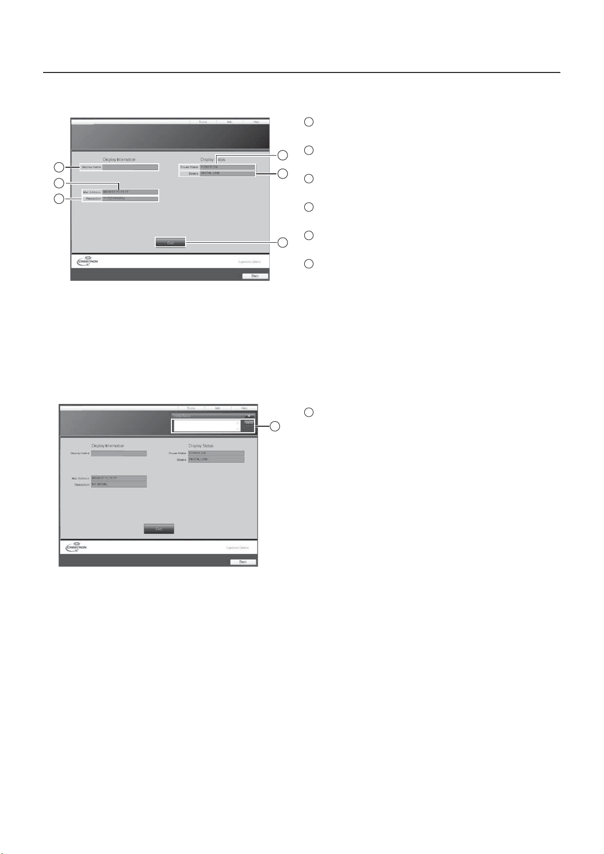
Info pa
Click Info on the operation page
Panasonic LCD Display
1
2
3
Name1234
1
Display Name
Displays the name of the Display.
2
4
Mac Address
Displays the MAC address
5
3
Resolution
Displays the resolution o
4
Power Status
the Display
Displays the status of the power
5
6
Source
Displays the selected video input.
6
Exit
Return the operation page.
elp pag
Click Help on the operation page
The Help Desk screen is displayed.
Panasonic LCD Display
Name1234
1
Help Des
1
ends or receive messages to the administrator who
ses Crestron Connected™
3
Page 34
JLink™ Protocol
y
s
.
.
k
ol
h
?
y
l
)
Off (
)
Off (
)
)
?
y
)
)
Off (
)
)
?
y
0
0
0
.
:
d
C
A
O
1
I
)
T
2
K
ON
?
y
?
y
asonic”
?
y
)
)
O?
y
y
”
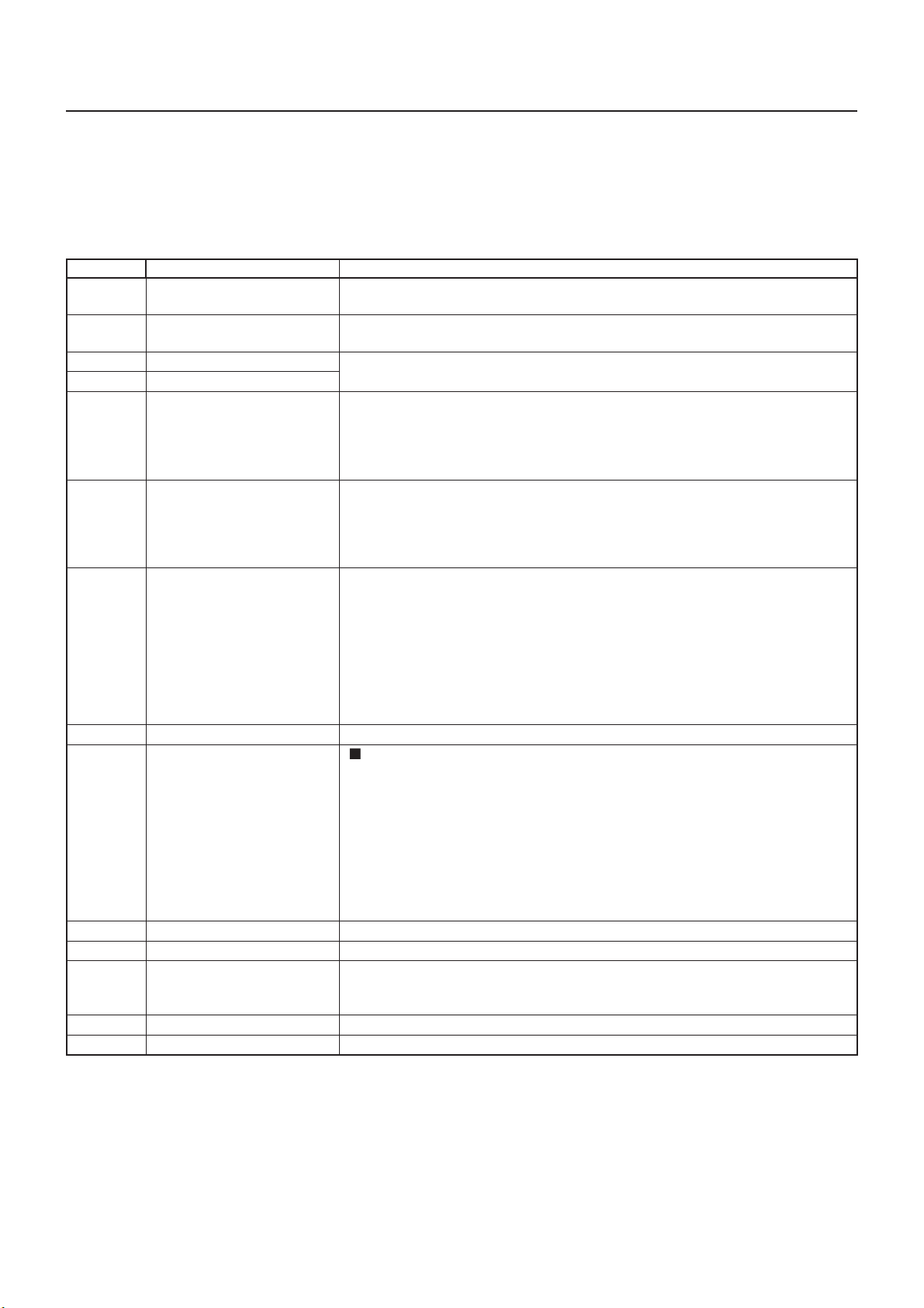
The network function of the unit conforms with PJLink™ class 1 and you can operate the following actions from your
omputer using PJLink™ protocol.
• Display setup
• Display status quer
Supported command
ommands to control the unit with PJLink™ protocol are shown in the table below
Command Control Remar
POWR
POWR?
AVMT
AVMT
RST
INST?
NAME
INF1
INF2
INF
LSS?
wer contr
ower status query
nput switc
nput switch quer
hutter contro
hutter control quer
Error status quer
amp status query
nput switch list query
isplay name quer
anufacturer name quer
odel name quer
Other information quer
lass information quer
rameter
0 = Standby 1 = Power “On”
arameter
0 = Standby 1 = Power “On”
rameter
ee the parameter for command INST
rameter
10 = Picture On (picture mute deactivated), 11 = Picture Off (picture on mute
0 = Audio On (audio mute deactivated), 21 = Audio
30 = Shutter mode
31 = Shutter mode On (picture and audio on mute
Parameter
11 = Picture Off (picture on mute
1 = Audio Off (audio on mute
30 = Shutter mode
31 = Shutter mode On (picture and audio on mute
Parameter
irst byte: Means fan error. 0 or 2.
econd byte: 0
Third byte:
ourth byte:
ifth byte:
ixth byte: Means other error. 0 or 2
eaning of the 0 – 2 settings
= Error is not detected, 2 = Error
Not supporte
INST ?Command
1INST=11 12 13 21 22 31 32 33 34 51 52 53
11: P
12:
LOT INPUT or SLOT INPUT
13: SLOT INPUT B
1: VIDE
: HDMI
: DV
51: Miracast(TM
: MEMORY VIEWER
The name set for [Name Change] in [Network Settings] is returned.
Returns “Pan
Returns “50LFC70U” / “65LFC70U” / “80LFC70U” (U model
Returns “50LFC70E” / “65LFC70E” / “80LFC70E” (E model
Returns “50LFC70W” / “65LFC70W” / “80LFC70W” (W model)
eturns version number
Returns “1
picture and audio mute deactivated
picture and audio mute deactivated
22: COMPONEN
: HDMI
4: DIGITAL LIN
2: Panasonic APPLICATI
audio on mute
PJLink™ security authentication
hen using PJLink with security authorization, either of the password set for administrator privileges and the
assword set for user privileges with Web browser control can be used as the password for PJLink (See page 24).
hen using PJLink without security authorization, set use without the password for administrator privileges and the
assword for user privileges of Web browser control
• PJLink™ is a pending trademark in Japan, the United States, and other countries and regions.
Concerning the speci cation of PJLink™, see the website of Japan Business Machine and Information System
ndustries Association (JBMIA) below:
http://pjlink.jbmia.or.jp/english/index.html
4
Page 35

Trademarks
osoft
®
a
®
®
are the registered trademarks or trademarks of
cou
.
C.
.
A
.
.
4
.
:
o
3
VGA is a trademark of International Business Machines Corporation.•
icr
•
icrosoft Corporation in the United States and/or other countries.
acintosh, Mac, Mac OS, OS X and Safari are the trademarks of Apple Inc. registered in the United States and•
ther
SVGA, XGA, SXGA and UXGA are registered trademarks of the Video Electronics Standard Association. •
Even if no special notation has been made of company or product trademarks, these trademarks have been fully
respected
PJLink is a pending trademark in Japan, the United States and other countries and regions.•
HDMI, the HDMI logo and High-De nition Multimedia Interface are trademarks or registered trademarks of HDMI •
Licensing LL
RoomView, Crestron RoomView and Fusion RV are registered trademarks of Crestron Electronics, Inc, and •
restron Connected is the trademark of Crestron Electronics, Inc.
iracast is the trademark of Wi-Fi Alliance
•
ndroid is the trademark of Google Inc
•
iPad, iPhone, iPod touch are trademarks or registered trademarks of Apple Inc. registered in the United States •
and other countries
Windows® Windows Vist
ntries.
, and Internet Explorer
USA only: Disposal may be regulated in your community due to environmental considerations. For disposal or
ecycling information, please visit Panasonic website:
ttp://www.panasonic.com/environmental
or call 1-888-769-0149.
Customer’s Record
The model number and serial number of this product can be found on its rear cover. You should note this serial
umber in the space provided below and retain this book, plus your purchase receipt, as a permanent record of
our purchase to aid in identi cation in the event of theft or loss, and for Warranty Service purposes
l Number
H-50LFC70U, TH-65LFC70U and TH-80LFC70U
anasonic System Communications Company of North America
Unit of Panasonic Corporation of North America
xecutive Of ce
Two Riverfront Plaza, Newark, New Jersey 07102-5490
anasonic Canada Inc.
5770 Ambler Drive
ississauga, Ontari
4W 2T
erial Number
eb Site : http://panasonic.net
Panasonic Corporation 201
 Loading...