

Page 1
Operating Instructions
Display Operations
Interactive Plasma Display
Model No.
TH-50PB2W
TH-65PB2W
English
Please read these instructions before operating your set
and retain them for future reference.
Page 2

Dear Panasonic Customer
Welcome to the Panasonic family of customers. We hope that you will have many years of
enjoyment from your new Plasma Display.
To obtain maximum benefit from your set, please read these Instructions before making
any adjustments, and retain them for future reference.
Retain your purchase receipt also, and note down the model number and serial number of
your set in the space provided on the rear cover of these instructions.
Visit our Panasonic Web Site http://panasonic.net
Table of Contents
Important Safety Notice ........................................... 3
Safety Precautions ................................................... 4
Accessories .............................................................. 7
Accessories Supply ................................................. 7
Remote Control Batteries ........................................ 7
Connections .............................................................. 8
AC cord connection and fi xing, cable fi xing ............. 8
Speaker connection ................................................. 9
Video equipment connection ................................... 9
VIDEO and COMPONENT / RGB IN connection .... 10
HDMI connection ....................................................11
DVI-D IN connection ...............................................11
PC Input Terminals connection .............................. 12
SERIAL Terminals connection ............................... 13
Power On / Off ......................................................... 14
Selecting the input signal ...................................... 16
Basic Controls ........................................................ 17
ASPECT Controls ................................................... 19
Digital Zoom ............................................................ 20
MULTI PIP ................................................................ 21
On-Screen Menu Displays ..................................... 22
Adjusting Pos./Size ................................................ 23
Picture Adjustments ............................................... 26
Advanced settings ................................................. 27
Picture Profi les ....................................................... 28
Saving profi les ....................................................... 29
Loading profi les ..................................................... 30
Editing profi les ....................................................... 30
Sound Adjustment .................................................. 31
SDI Sound Output ................................................. 31
Setup menu ............................................................. 32
Day/Time Setup / On/Off Timer Setup ................... 33
Day/Time Setup ..................................................... 33
On/Off Timer Setup................................................ 33
Touch-Pen Settings ................................................ 34
MULTI PIP Settings ................................................. 36
Screensaver (For preventing image retention) .... 37
Setup of Screensaver Time ................................... 38
Reduces screen image retention .......................... 39
Extended life settings ............................................ 39
ECO Mode settings ................................................. 42
Customizing the Input labels ................................. 43
Function Button Settings ....................................... 44
No activity power off .............................................. 45
Menu Display Duration / OSD Brightness ............ 45
OSD Language ........................................................ 45
Display orientation ................................................. 45
Setup for Input Signals .......................................... 46
Component / RGB-in select ................................... 46
YUV / RGB-in select .............................................. 46
Signal menu .......................................................... 47
Options Adjustments ............................................. 50
Weekly Command Timer ....................................... 53
Audio input select .................................................. 55
Touch Panel settings (Settings when using Touch
Panel) .................................................................... 56
Input Search .......................................................... 57
Troubleshooting ..................................................... 58
List of Aspect Modes ............................................. 59
Applicable Input Signals ........................................ 60
Shipping condition ................................................. 61
Command list of Weekly Command Timer ........... 62
Specifi cations ......................................................... 63
2
Page 3
Important Safety Notice
WARNING
1) To prevent damage which may result in fi re or shock hazard, do not expose this appliance to dripping
or splashing.
Do not place containers with water (fl ower vase, cups, cosmetics, etc.) above the set. (including on
shelves above, etc.)
No naked fl ame sources, such as lighted candles, should be placed on / above the set.
2) To prevent electric shock, do not remove cover. No user serviceable parts inside. Refer servicing to qualifi ed
service personnel.
3) Do not remove the earthing pin on the power plug. This apparatus is equipped with a three pin earthing-type
power plug. This plug will only fi t an earthing-type power outlet. This is a safety feature. If you are unable to
insert the plug into the outlet, contact an electrician.
Do not defeat the purpose of the earthing plug.
4) To prevent electric shock, ensure the earthing pin on the AC cord power plug is securely connected.
CAUTION
This appliance is intended for use in environments which are relatively free of electromagnetic fi elds.
Using this appliance near sources of strong electromagnetic fi elds or where electrical noise may overlap with the
input signals could cause the picture and sound to wobble or cause interference such as noise to appear.
To avoid the possibility of harm to this appliance, keep it away from sources of strong electromagnetic fi elds.
IMPORTANT INFORMATION
If a display is not positioned in a suffi ciently stable location, it can be potentially hazardous due to falling. Many
injuries, particularly to children, can be avoided by taking simple precautions such as:
• Using cabinets or stands recommended by the manufacturer of the display.
• Only using furniture that can safely support the display.
• Ensuring the display is not overhanging the edge of the supporting furniture.
• Not placing the display on tall furniture (for example, cupboards or bookcases) without anchoring both the furniture
and the display to a suitable support.
• Not standing the displays on cloth or other materials placed between the display and supporting furniture.
• Educating children about the dangers of climbing on furniture to reach the display or its controls.
Trademark Credits
• VGA is a trademark of International Business Machines Corporation.
• Macintosh is a registered trademark of Apple Inc., USA.
• SVGA, XGA, SXGA and UXGA are registered trademarks of the Video Electronics Standard Association.
Even if no special notation has been made of company or product trademarks, these trademarks have been fully respected.
• HDMI, the HDMI Logo, and High-Defi nition Multimedia Interface are trademarks or registered trademarks of HDMI
Licensing LLC in the United States and other countries.
Note:
Do not allow a still picture to be displayed for an extended period, as this can cause a permanent image retention
to remain on the Plasma Display.
Examples of still pictures include logos, video games, computer images, teletext and images displayed in 4:3 mode.
3
Page 4
Safety Precautions
WARNING
Setup
This Plasma Display is for use only with the following optional accessories. Use with any other type of optional
accessories may cause instability which could result in the possibility of injury.
(All of the following accessories are manufactured by Panasonic Corporation.)
• Pedestal .................................................................................... TY-ST42P50 (for TH-50PB2W),
TY-ST65P20 (for TH-65PB2W)
• Mobile stand for Display ............................................................ TY-ST50PB2 (for TH-50PB2W),
TY-ST65PF1 (for TH-65PB2W),
TY-ST65PB2 (for TH-65PB2W),
• Mobile stand .............................................................................. TY-ST58PF20 (for TH-50PB2W)
• Wall-hanging bracket (vertical) .................................................. TY-WK42PV20 (for TH-50PB2W),
• Wall-hanging bracket (angled) .................................................. TY-WK42PR20 (for TH-50PB2W),
TY-WK65PR20 (for TH-65PB2W)
• Ceiling-hanging bracket ............................................................ TY-CE42PS20 (for TH-50PB2W)
• Touch Panel .............................................................................. TY-TP50P30K (for TH-50PB2W),
TY-TP65P30K (for TH-65PB2W)
• BNC Dual Video Terminal Board ............................................... TY-FB9BD
• HD-SDI Terminal Board ............................................................. TY-FB9HD
• HD-SDI Terminal Board with audio ........................................... TY-FB10HD
• Dual Link HD-SDI Terminal Board ............................................. TY-FB11DHD
• Dual HDMI Terminal Board ....................................................... TY-FB10HMD
• DVI-D Terminal Board ............................................................... TY-FB11DD
• AV Terminal Box ........................................................................ TY-TB10AV
• Electronic Pen for Interactive Plasma Display .......................... TY-TPEN2
• Electronic Pen Adapter for Interactive Plasma Display ............. TY-TAD20
• Electronic Pen Charger for Interactive Plasma Display ............ TY-TCG20
• Wireless Module ........................................................................ ET-WM200E
Always be sure to ask a qualifi ed technician to carry out set-up.
Small parts can present choking hazard if accidentally swallowed. Keep small parts away from young children. Discard
unneeded small parts and other objects, including packaging materials and plastic bags/sheets to prevent them from
being played with by young children, creating the potential risk of suffocation.
Do not place the Plasma Display on sloped or unstable surfaces, and ensure that the Plasma Display does
not hang over the edge of the base.
• The Plasma Display may fall off or tip over.
Do not place any objects on top of the Plasma Display.
• If water is spills onto the Plasma Display or foreign objects get inside it, a short-circuit may occur which could result
in fi re or electric shock. If any foreign objects get inside the Plasma Display, please consult your local Panasonic
dealer.
Transport only in upright position!
• Transporting the unit with its display panel facing upright or downward may cause damage to the internal
circuitry.
Ventilation should not be impeded by covering the ventilation openings with items such as newspapers, table
cloths and curtains.
For suffi cient ventilation;
If using the pedestal (optional accessory), leave a space of 10 cm or more at the top, left and right, and 7 cm
or more at the rear, and also keep the space between the bottom of the display and the fl oor surface.
If using some other setting-up method, follow the manual of it. (If there is no specifi c indication of installation
dimension in the installation manual, leave a space of 10 cm or more at the top, bottom, left and right, and 7
cm or more at the rear.)
When installing the Plasma Display vertically;
Turn up the power switch for the upward direction when you install the Plasma Display vertically.
And set “Display orientation” to “Portrait” in Setup menu. (see page 45)
4
Page 5

Safety Precautions
When using the Plasma Display
The Plasma Display is designed to operate on 220 - 240 V AC, 50/60 Hz.
Do not cover the ventilation holes.
• Doing so may cause the Plasma Display to overheat, which can cause fi re or damage to the Plasma Display.
Do not stick any foreign objects into the Plasma Display.
• Do not insert any metal or fl ammable objects into the ventilations holes or drop them onto the Plasma Display, as
doing so can cause fi re or electric shock.
Do not remove the cover or modify it in any way.
• High voltages which can cause severe electric shocks are present inside the Plasma Display. For any inspection,
adjustment and repair work, please contact your local Panasonic dealer.
Ensure that the mains plug is easily accessible.
An apparatus with CLASS I construction shall be connected to a mains socket outlet with a protective earthing connection.
Do not use any power supply cord other than that provided with this unit.
• Doing so may cause fi re or electric shocks.
Securely insert the power supply plug as far as it will go.
• If the plug is not fully inserted, heat may be generated which could cause fi re. If the plug is damaged or the wall
socket is loose, they shall not be used.
Do not handle the power supply plug with wet hands.
• Doing so may cause electric shocks.
Do not do anything that may damage the power cable. When disconnecting the power cable, pull on the plug body, not the cable.
• Do not damage the cable, make any modifi cations to it, place heavy objects on top of it, heat it, place it near any
hot objects, twist it, bend it excessively or pull it. To do so may cause fi re and electric shock. If the power cable is
damaged, have it repaired at your local Panasonic dealer.
If the Plasma Display is not going to be used for any prolonged length of time, unplug the power supply plug
from the wall outlet.
If problems occur during use
If a problem occurs (such as no picture or no sound), or if smoke or an abnormal odour starts to come out
from the Plasma Display, immediately unplug the power supply plug from the wall outlet.
• If you continue to use the Plasma Display in this condition, fi re or electric shock could result. After checking that
the smoke has stopped, contact your local Panasonic dealer so that the necessary repairs can be made. Repairing
the Plasma Display yourself is extremely dangerous, and shall never be done.
If water or foreign objects get inside the Plasma Display, if the Plasma Display is dropped, or if the cabinet
becomes damages, disconnect the power supply plug immediately.
• A short circuit may occur, which could cause fi re. Contact your local Panasonic dealer for any repairs that need to
be made.
5
Page 6
Safety Precautions
CAUTION
When using the Plasma Display
Do not bring your hands, face or objects close to the ventilation holes of the Plasma Display.
• Heated air comes out from the ventilation holes at the top of Plasma Display will be hot. Do not bring your hands
or face, or objects which cannot withstand heat, close to this port, otherwise burns or deformation could result.
Be sure to disconnect all cables before moving the Plasma Display.
• If the Plasma Display is moved while some of the cables are still connected, the cables may become damaged,
and fi re or electric shock could result.
Disconnect the power supply plug from the wall socket as a safety precaution before carrying out any
cleaning.
• Electric shocks can result if this is not done.
Clean the power cable regularly to prevent it becoming dusty.
• If dust built up on the power cord plug, the resultant humidity can damage the insulation, which could result in fi re.
Pull the power cord plug out from the wall outlet and wipe the mains lead with a dry cloth.
Do not burn or breakup batteries.
• Batteries must not be exposed to excessive heat such as sunshine, fi re or the like.
This Plasma Display radiates infrared rays, therefore it may affect other infrared communication equipment.
Install your infrared sensor in a place away from direct or refl ected light from your Plasma Display.
Cleaning and maintenance
The front of the display panel has been specially treated. Wipe the panel surface gently using only a cleaning
cloth or a soft, lint-free cloth.
• If the surface is particularly dirty, wipe with a soft, lint-free cloth which has been soaked in pure water or water in
which neutral detergent has been diluted 100 times, and then wipe it evenly with a dry cloth of the same type until
the surface is dry.
• Do not scratch or hit the surface of the panel with fi ngernails or other hard objects, otherwise the surface may
become damaged. Furthermore, avoid contact with volatile substances such as insect sprays, solvents and thinner,
otherwise the quality of the surface may be adversely affected.
If the cabinet becomes dirty, wipe it with a soft, dry cloth.
• If the cabinet is particularly dirty, soak the cloth in water to which a small amount of neutral detergent has been
added and then wring the cloth dry. Use this cloth to wipe the cabinet, and then wipe it dry with a dry cloth.
• Do not allow any detergent to come into direct contact with the surface of the Plasma Display. If water droplets get
inside the unit, operating problems may result.
• Avoid contact with volatile substances such as insect sprays, solvents and thinner, otherwise the quality of the
cabinet surface may be adversely affected or the coating may peel off. Furthermore, do not leave it for long periods
in contact with articles made from rubber or PVC.
6
Page 7
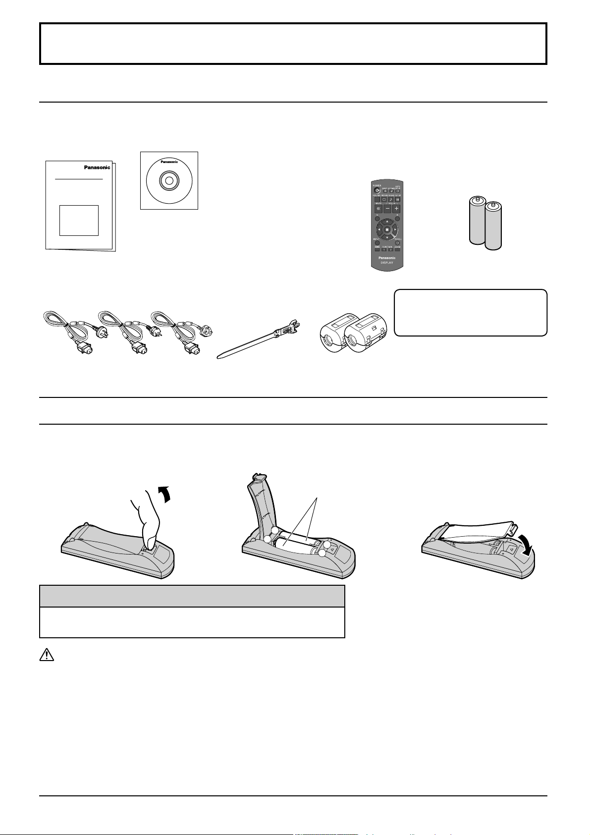
Accessories
Accessories Supply
Check that you have the accessories and items shown
Operating
Instruction book
Power supply cord Clamper × 1
Software CD-ROM × 1
• Panasonic WhiteBoard Software
• Operating Instructions
Display Operations
Network Operations
Electronic Pen Operations
• Software license statements
GNU GENERAL PUBLIC LICENSE
GNU LESSER GENERAL PUBLIC LICENSE
TMME289
Remote Control Batteries
Remote Control
Transmitter
N2QAYB000691
Ferrite core × 2
J0KG00000014
Use the Ferrite cores to comply with the EMC standard.
(refer to “Operating Instructions, Network Operations”)
Electronic Pen set
Refer to “Operating Instructions,
Electronic Pen Operations”.
Batteries for the Remote
Control Transmitter
(R6 (UM3) Size × 2)
Requires two R6 batteries.
1. Pull and hold the hook, then open
the battery cover.
2. Insert batteries - note correct
polarity ( + and -).
“R6 (UM3)” size
-
+
+
-
3. Replace the cover.
Helpful Hint:
For frequent remote control users, replace old batteries with Alkaline
batteries for longer life.
Precaution on battery use
Incorrect installation can cause battery leakage and corrosion that will damage the remote control transmitter.
Disposal of batteries should be in an environment-friendly manner.
Observe the following precaution:
1. Batteries shall always be replaced as a pair. Always use new batteries when replacing the old set.
2. Do not combine a used battery with a new one.
3. Do not mix battery types (example: “Zinc Carbon” with “Alkaline”).
4. Do not attempt to charge, short-circuit, disassemble, heat or burn used batteries.
5.
Battery replacement is necessary when remote control acts sporadically or stops operating the Plasma Display set.
6. Do not burn or breakup batteries.
7. Batteries must not be exposed to excessive heat such as sunshine, fi re or the like.
7
Page 8
Connections
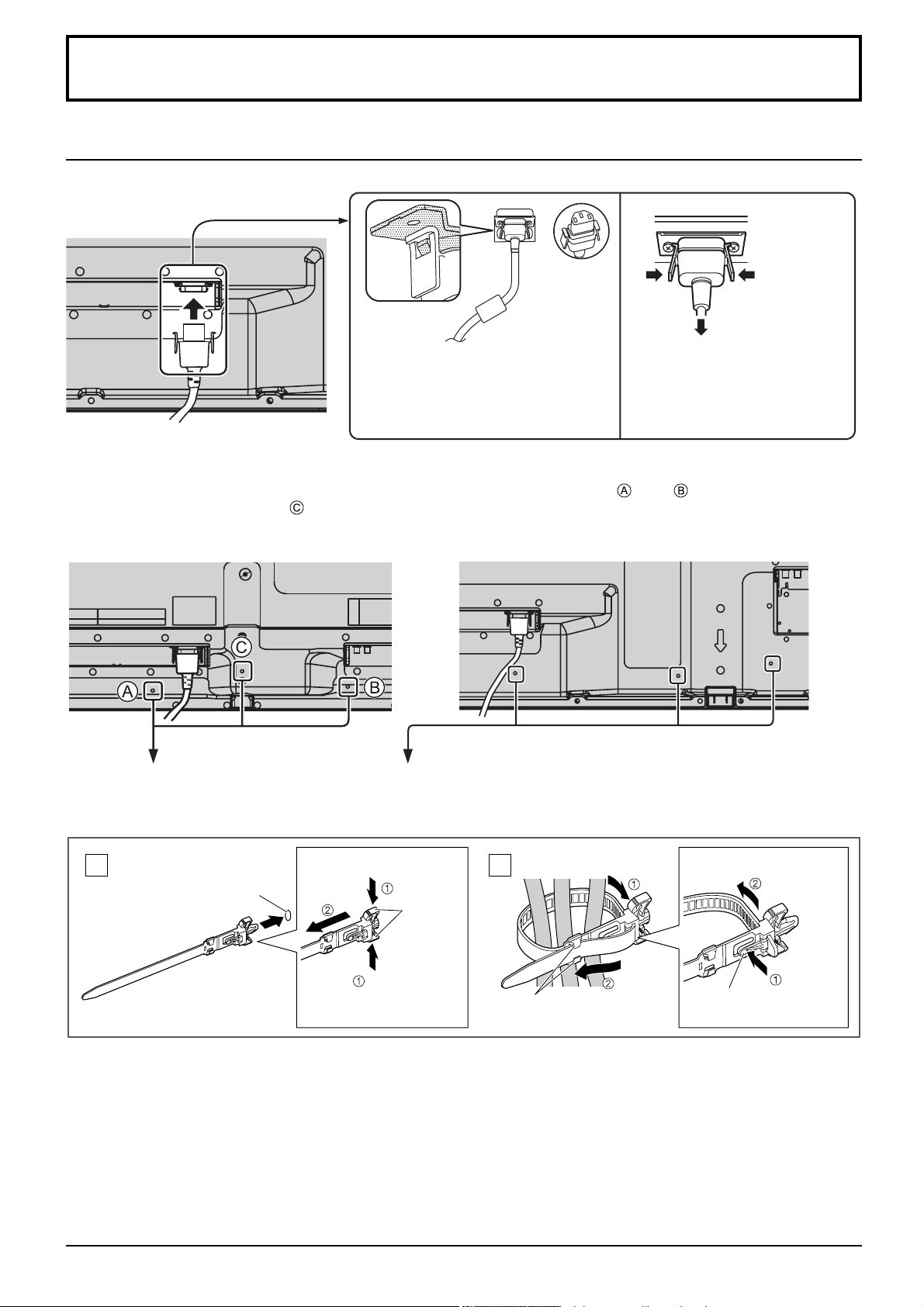
AC cord connection and fi xing, cable fi xing
AC cord fi xing
Unplug the AC cord
Unplug the AC cord pressing the
Plug the AC cord into the display unit.
Plug the AC cord until it clicks.
Note:
Make sure that the AC cord is locked on
both the left and right sides.
When using the Wall-hanging bracket (vertical) (for TH-50PB2W)
Note:
When using the Wall-hanging bracket (vertical)(TY-WK42PV20), use the holes and to secure the cables. If
the clamper is used on the hole , the cables may be caught by the wall-hanging bracket.
two knobs.
Note:
When disconnecting the AC cord, be
absolutely sure to disconnect the AC
cord plug at the socket outlet fi rst.
TH-50PB2W TH-65PB2W
Using the clamper
Secure any excess cables with clamper as required.
Note:
One clamper is supplied with this unit. In case of securing cables at three positions, please purchase it separately.
Attach the clamper
1
Insert the clamper
in a hole.
hole
To remove from the unit:
snaps
Keep pushing
both side
snaps
Bundle the cables
2
hooks
Set the
tip in the
hooks
To loosen:
knob
Keep
pushing
the knob
8
Page 9
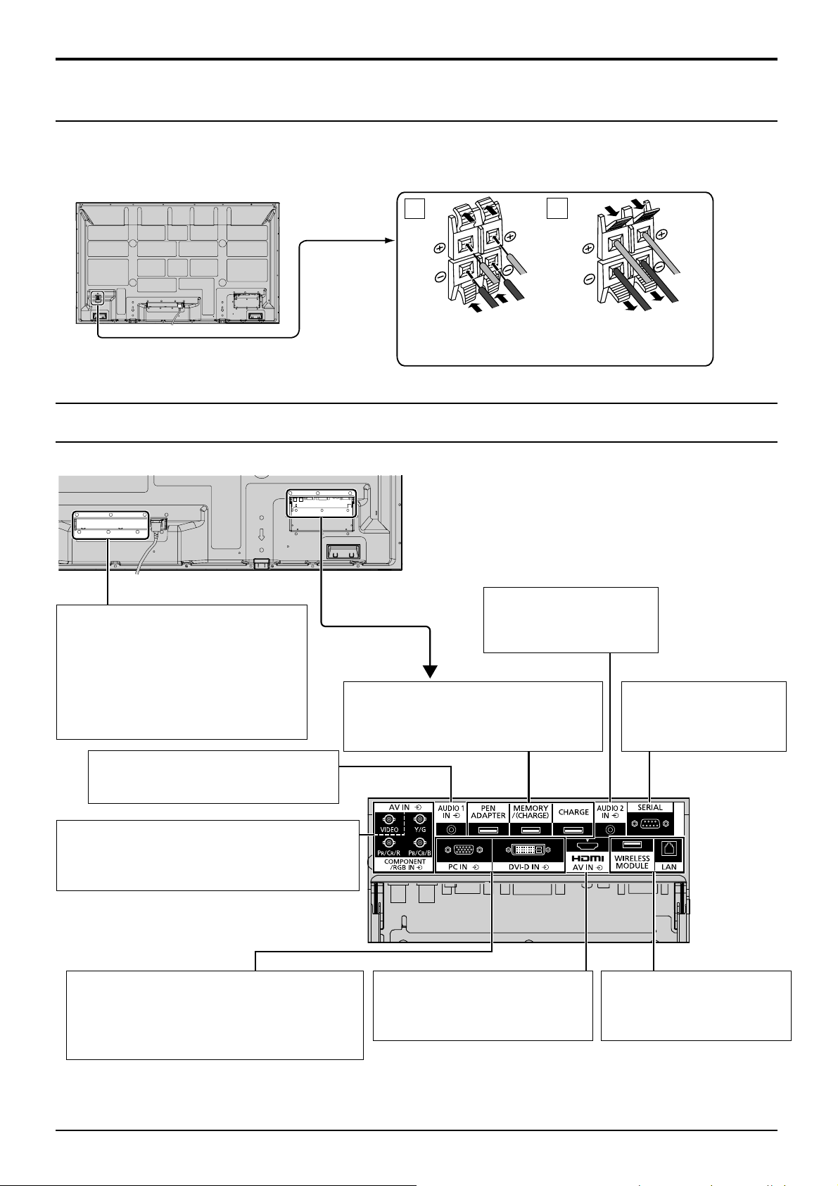
Speaker connection
For TH-50PB2W
Please use 6 Ω/8 W speaker.
For TH-65PB2W
Please use 8 Ω/10 W speaker.
Connections
1
2
Video equipment connection
Ex. TH-65PB2W
SLOT: Terminal board (optional
accessories) insert slot
(see page 4)
Note:
The right side slot is for terminal board
with 2-slot width. The terminal board
with 1-slot width does not function
when installed in the right side slot.
AUDIO 1 IN: Audio input
terminal shared with VIDEO and
COMPONENT/RGB IN. (see page 10)
PEN ADAPTER, MEMORY/(CHARGE),
CHARGE:
Refer to “Operating Instructions,
Electronic Pen Operations”.
(L)
(R)
While pressing the lever,
insert the core wire.
Red
Black
AUDIO 2 IN:
Audio input terminal shared
with DVI-D IN and PC IN.
(see page 11, 12)
(R)
Return the lever.
SERIAL:
Control the Plasma Display
by connecting to PC.
(see page 13)
(L)
Red
Black
AV IN (VIDEO): Composite Video Input
Terminal (see page 10)
COMPONENT/RGB IN:
Terminals are on the bottom side of the Plasma
Display.
DVI-D IN: DVI-D Input Terminal (see page 11)
PC IN:
PC Input Terminal
Connect to video terminal of PC or
equipment with Y, PB(CB) and PR(CR)
output (see page 12).
Component/RGB Video Input
Terminal (
see page 10
)
AV IN (HDMI): HDMI Input
Terminal (see page 11)
Connect to video equipment such
as VCR or DVD player.
WIRELESS MODULE, LAN:
Refer to “Operating
Instructions, Network
Operations”.
9
Page 10
Connections
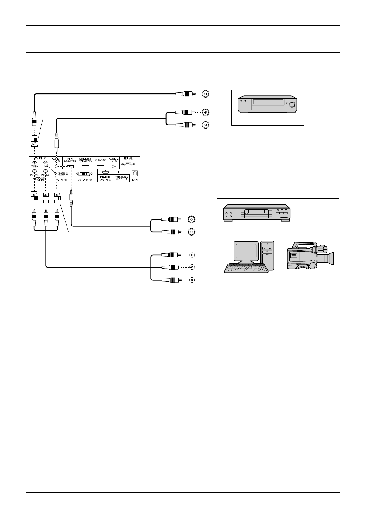
VIDEO and COMPONENT / RGB IN connection
Note:
Additional equipment, cables and adapter plugs
shown are not supplied with this set.
RCA-BNC
Adapter plug
Stereo mini plug (M3)
AUDIO 1 IN:
Shared with VIDEO and
COMPONENT/RGB IN
Notes:
• Change the “Component/RGB-in select” setting in the “Setup”
menu to “Component” (when Component signal connection) or
“RGB” (when RGB signal connection). (see page 46)
• Signals input to COMPONENT/RGB IN terminals correspond to
Sync on G or Sync on Y.
L
R
VIDEO
OUT
AUDIO
OUT
VCR
RCA-BNC
Adapter plug
L
R
Y
PB
PR
AUDIO
OUT
OUT
DVD Player
Computer RGB Camcorder
, Y , P B , P R
10
Page 11
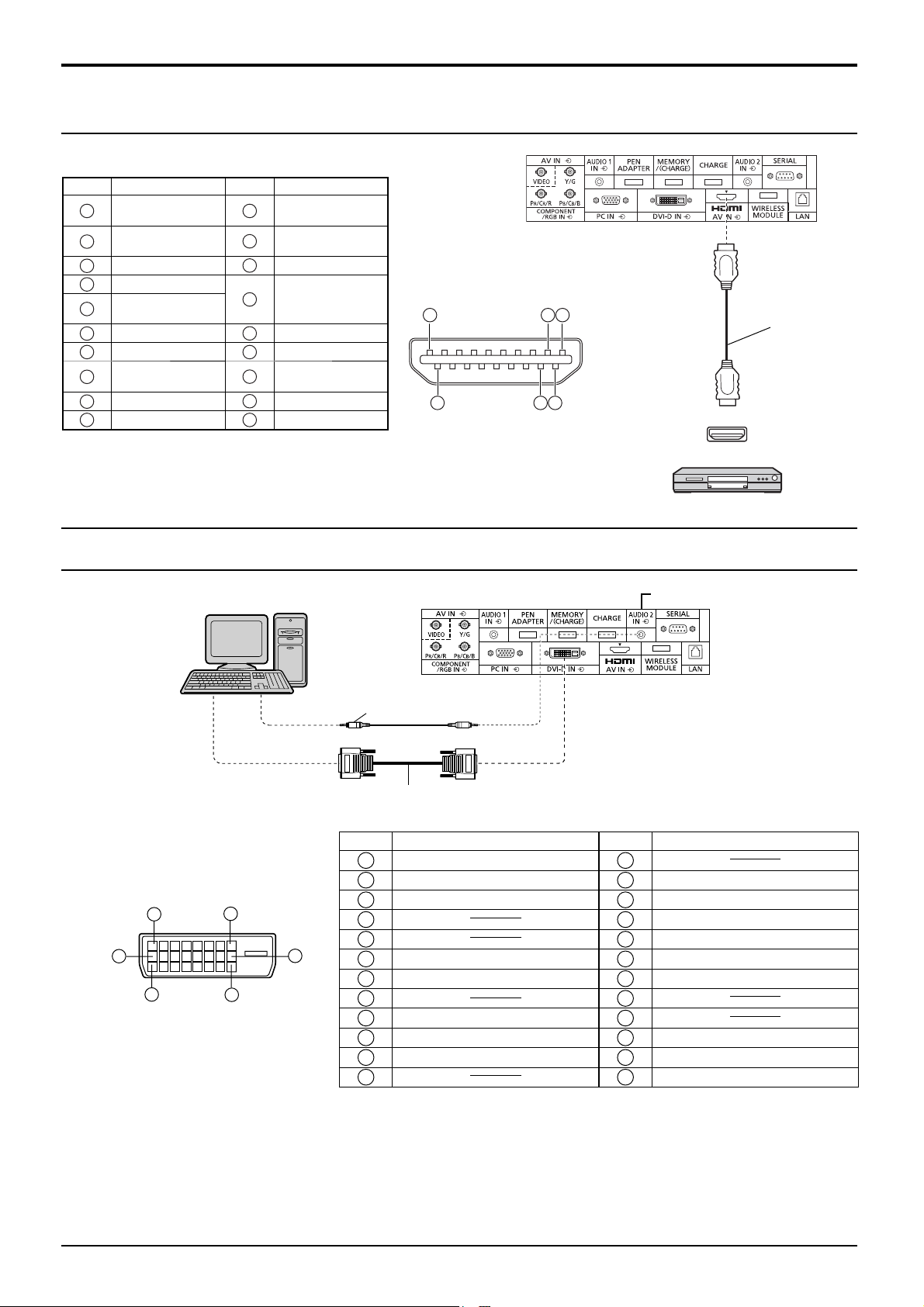
HDMI connection
[Pin assignments and signal names]
Pin No.
10
Signal name
1
T.M.D.S Data2+
T.M.D.S Data2
2
Shield
3
T.M.D.S Data2-
4
T.M.D.S Data1+
T.M.D.S Data1
5
Shield
6
T.M.D.S Data1-
7
T.M.D.S Data0+
T.M.D.S Data0
8
Shield
9
T.M.D.S Data0T.M.D.S Clock+
Pin No.
Note:
Additional equipment and HDMI cable shown are not supplied with this set.
Signal name
T.M.D.S Clock
11
Shield
12
T.M.D.S Clock-
13
CEC
Reserved
14
(N.C. on device)
15
SCL
16
SDA
DDC/CEC
17
Ground
18
+5V Power
Hot Plug Detect
19
1
19
18
3
2
4
Connections
HDMI cable
HDMI
AV OUT
DVD player
DVI-D IN connection
PC with DVI-D
video out
Stereo mini plug (M3)
DVI-video cable (Within 5 m)
DVI-D Input Connector
Pin Layouts
1
9
17
8
24
Connection port view
16
Pin No.
Signal Name
T.M.D.S. data 2-
1
T.M.D.S. data 2+
2
T.M.D.S. data 2 shield
3
4
5
DDC clock
6
DDC data
7
8
T.M.D.S. data 1-
9
T.M.D.S. data 1+
10
T.M.D.S. data 1 shield
11
12 24
Pin No.
Notes:
• Additional equipment and cables shown are not supplied with this set.
• Use the DVI-D cable complying with the DVI standard. Image deterioration may occur depending on the length or
the quality of the cable.
Shared with PC IN.
Signal Name
13
+5 V DC
14
Ground
15
Hot plug detect
16
T.M.D.S. data 0-
17
T.M.D.S. data 0+
18
T.M.D.S. data 0 shield
19
20
21
T.M.D.S. clock shield
22
T.M.D.S. clock+
23
T.M.D.S. clock-
11
Page 12
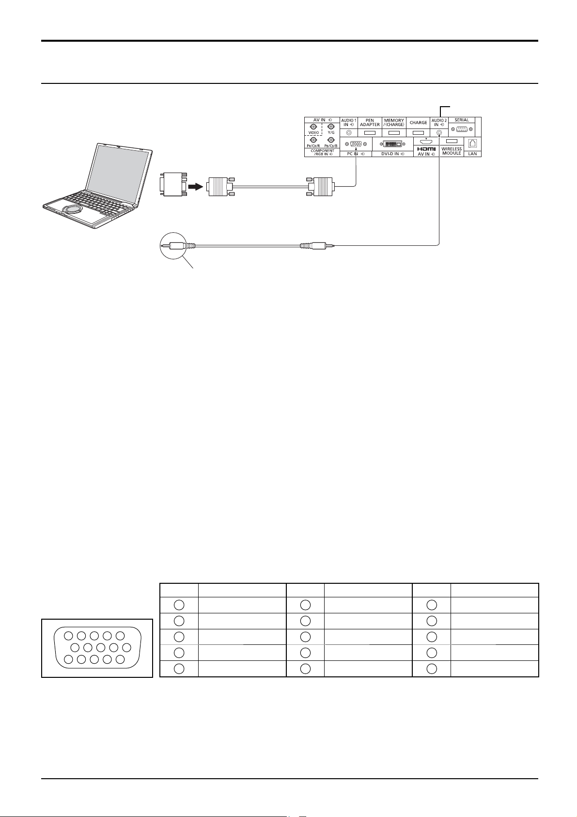
Connections
PC Input Terminals connection
COMPUTER
Conversion adapter
(if necessary)
RGB
PC cable
(Female)
Mini D-sub 15p
(Male)
Shared with DVI-D IN.
Audio
Connect a cable which matches
the audio output terminal on the computer.
Stereo mini plug (M3)
Notes:
• With regard to the typical PC input signals that are described in the applicable input signals list (see page 60), adjustment
values such as for the standard picture positions and sizes have already been stored in this unit. You can add up to eight
PC input signal types that are not included in the list.
• Computer signals which can be input are those with a horizontal scanning frequency of 15 to 110 kHz and vertical scanning
frequency of 48 to 120 Hz. (However, the image will not be displayed properly if the signals exceed 1,200 lines.)
• The display resolution is a maximum of 1,440 × 1,080 dots when the aspect mode is set to “4:3”, and 1,920 × 1,080
dots when the aspect mode is set to “16:9”. If the display resolution exceeds these maximums, it may not be possible
to show fi ne detail with suffi cient clarity.
• The PC input terminals are DDC2B-compatible. If the computer being connected is not DDC2B-compatible, you will
need to make setting changes to the computer at the time of connection.
• Some PC models cannot be connected to the set.
• There is no need to use an adapter for computers with DOS/V compatible Mini D-sub 15P terminal.
• The computer shown in the illustration is for example purposes only.
• Additional equipment and cables shown are not supplied with this set.
• Do not set the horizontal and vertical scanning frequencies for PC signals which are above or below the specifi ed
frequency range.
• Component Input is possible with the pin 1, 2, 3 of the Mini D-sub 15P Connector.
• Change the “Component/RGB-in select” setting in the “Setup” menu to “Component”
(when Component signal connection) or “RGB” (when RGB signal connection). (see page 46)
Signal Names for Mini D-sub 15P Connector
Pin No. Signal Name Pin No. Signal Name Pin No. Signal Name
4 5
10
15 14 13 12 11
1
2
1
2
3
6 7 8 3 9
4
5
R (PR/CR)
G (Y)
B (PB/CB)
NC (not connected)
GND (Ground)
Pin Layout for PC Input
Terminal
12
6
7
8
9
10
GND (Ground)
GND (Ground)
GND (Ground)
+5 V DC
GND (Ground)
11
NC (not connected)
12
13
14
15
HD/SYNC
SDA
VD
SCL
Page 13
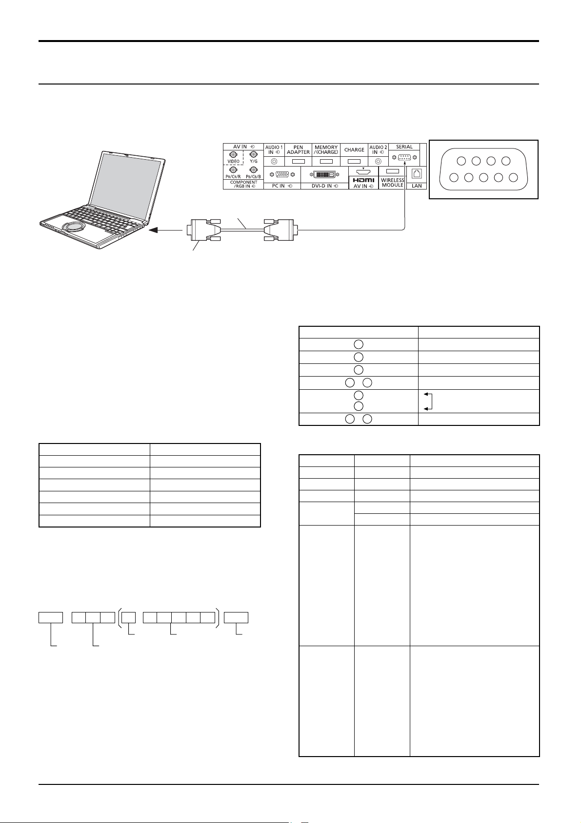
Connections
SERIAL Terminals connection
The SERIAL terminal is used when the Plasma Display is controlled by a computer.
Note: To use serial control for this unit, make sure to set the “Control I/F Select” in the “Network Setup” menu to
“RS-232C”. (refer to “Operating Instructions, Network Operations”)
COMPUTER
(Male)
6789
13452
RS-232C Straight cable
D-sub 9p
(Female)
Notes:
• Use the RS-232C straight cable to connect the computer to the Plasma Display.
• The computer shown is for example purposes only.
• Additional equipment and cables shown are not supplied
with this set.
The SERIAL terminal conforms to the RS-232C interface
specifi cation, so that the Plasma Display can be controlled
by a computer which is connected to this terminal.
The computer will require software which allows the
sending and receiving of control data which satisfies
the conditions given below. Use a computer application
such as programming language software. Refer to the
documentation for the computer application for details.
Communication parameters
Signal level RS-232C compliant
Synchronization method Asynchronous
Baud rate 9600 bps
Parity None
Character length 8 bits
Stop bit 1 bit
Flow control None
Basic format for control data
The transmission of control data from the computer
starts with a STX signal, followed by the command, the
parameters, and lastly an ETX signal in that order. If there
Signal names for D-sub 9P connector
Pin No. Details
2
3
5
4
6
•
7
8
1
9
•
These signal names are those of computer specifi cations.
Command
Command Parameter Control details
PON None Power ON
POF None Power OFF
AVL ** Volume 00 - 63
AMT
IMS None
0 Audio MUTE OFF
1 Audio MUTE ON
SL1
S1A
S1B
VD1
YP1
are no parameters, then the parameter signal does not
need to be sent.
STX C1 C2 C3 P1 P2 P3 P4: P5 ETX
Start
(02h)
Colon Parameter(s)
3-character
command (3 bytes)
(1 - 5 bytes)
End
(03h)
Notes:
• If multiple commands are transmitted, be sure to wait for
the response for the fi rst command to come from this unit
before sending the next command.
• If an incorrect command is sent by mistake, this unit will
send an “ER401” command back to the computer.
• S1A and S1B of Command IMS are available only when
a dual input terminal board is attached.
• Consult your local Panasonic dealer for detail instructions
on command usage.
DAM None
With the power off, this display responds to PON command
only.
HM1
DV1
PC1
NW1
WB1
ZOOM
FULL
JUST
NORM
ZOM2
ZOM3
SJST
SNOM
SFUL
14:9
Pin layout for SERIAL Terminal
R X D
T X D
GND
Non use
(Shorted in this set)
NC
Input select (toggle)
SLOT input (SLOT INPUT)
SLOT input (SLOT INPUT A)
SLOT input (SLOT INPUT B)
VIDEO input (VIDEO)
COMPONENT/RGB IN input
(COMPONENT)
HDMI input (HDMI)
DVI-D IN input (DVI)
PC IN input (PC)
Network input (NETWORK)
WhiteBoard input (WHITEBOARD)
Screen mode select (toggle)
Zoom, Zoom1
16:9
Just, Just1 (For Video/SD/HD signal)
4:3, 4:3 (1)
Zoom2 (For Video/SD/HD signal)
Zoom3 (For Video/SD/HD signal)
Just2 (For HD signal)
4:3 (2) (For HD signal)
4:3 Full (For HD signal)
14:9 (For Video/SD/HD signal)
13
Page 14
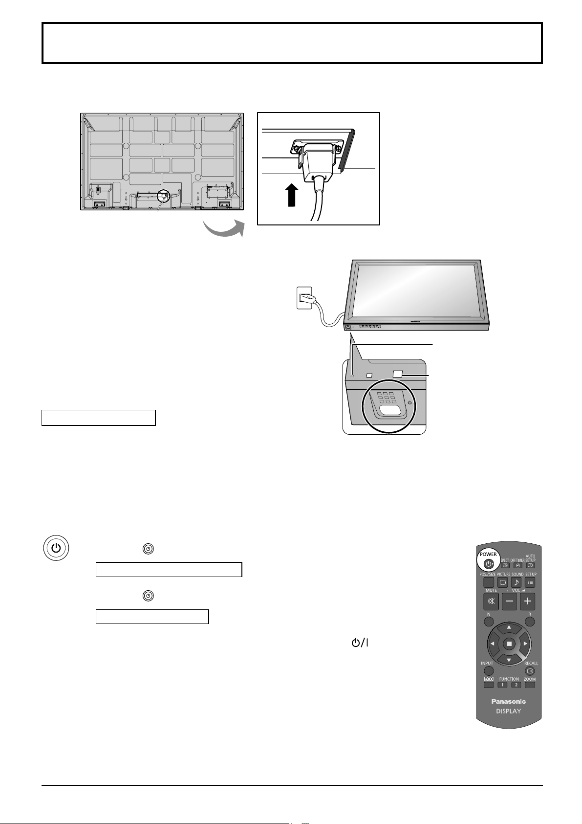
Power On / Off
Connecting the AC cord plug to the Plasma Display.
Connecting the plug to the Wall Outlet
Notes:
• Main plug types vary between countries. The power
plug shown at right may, therefore, not be the type
fi tted to your set.
• When disconnecting the AC cord, be absolutely
sure to disconnect the AC cord plug at the socket
outlet fi rst.
INPUT MENU ENTER/+/VOL-/
Power Indicator
Press the Power switch on the Plasma Display to
turn the set on: Power-On.
Power Indicator: Green
[Starting up the network]
It takes some time for the network to start up just
after the power is turned on.
During that time, “Network Setup” in the “Setup” menu
is grayed out and cannot be set.
Press the button on the remote control to turn the Plasma Display off.
Power Indicator: Red (standby)
Press the
Power Indicator: Green
Turn the power to the Plasma Display off by pressing the switch on the
unit, when the Plasma Display is on or in standby mode.
button on the remote control to turn the Plasma Display on.
Remote Control Sensor
14
Note:
During operation of the power management function, the power indicator turns
orange in the power off state.
Page 15
Power On / Off
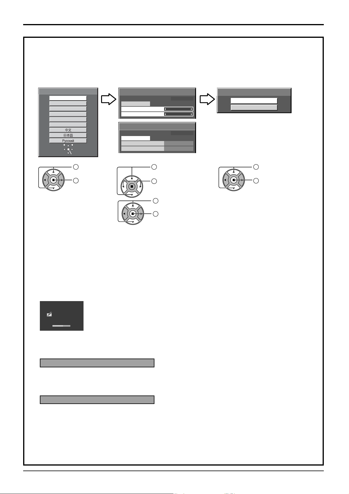
When fi rst switching on the unit
Following screen will be displayed when the unit is turned on for the fi rst time.
Select the items with the remote control. Unit buttons are invalid.
OSD Language Day/Time Setup Display orientation
OSD Language
English (UK)
ENGLISH (US)
Deutsch
Français
Italiano
Español
SetSelect
1
Select the
language.
2
Set.
Day/Time Setup
Set
Day
Time
Day/Time Setup
Set
Day
Time
Time MON 99:99
MON
99:99
Time MON 99:99
TUE
10:00
1
Select “Day” or
“Time”.
2
Setup “Day” or
Display orientation
Landscape
Portrait
1
For vertical installation,
select “Portrait”.
2
Set.
“Time”.
1
Select “Set”.
2
Set.
Notes:
• Once the items are set, the screens won't be displayed when switching on the unit next time.
• After the setting, the items can be changed in the following menus.
OSD Language (see page 45)
Day/Time Setup (see page 33)
Display orientation (see page 45)
Power ON message
The following message may be displayed when turning the unit power ON:
Easy WhiteBoard Startup screen
Easy WhiteBoard
NOW LOADING…
When the power is turned ON with the Input switch of the WHITEBOARD, the built-in WhiteBoard software
“Easy WhiteBoard” starts up.
No activity power off Precautions
’No activity power off’ is enabled.
If “No activity power off” in Setup menu is set to “Enable”, a warning message is displayed every time the
power is turned ON. (see page 45)
Power Management Information
Last turn off due to 'Power management'.
If “PC Power management” or “DVI-D Power management” is functioned, an information message is
displayed every time the power is turned ON. (see page 42)
These message displays can be set with the following menu: Options menu
Power On Message (No activity power off)
(see page 52)
Power On Message (Power Management)
(see page 52)
15
Page 16
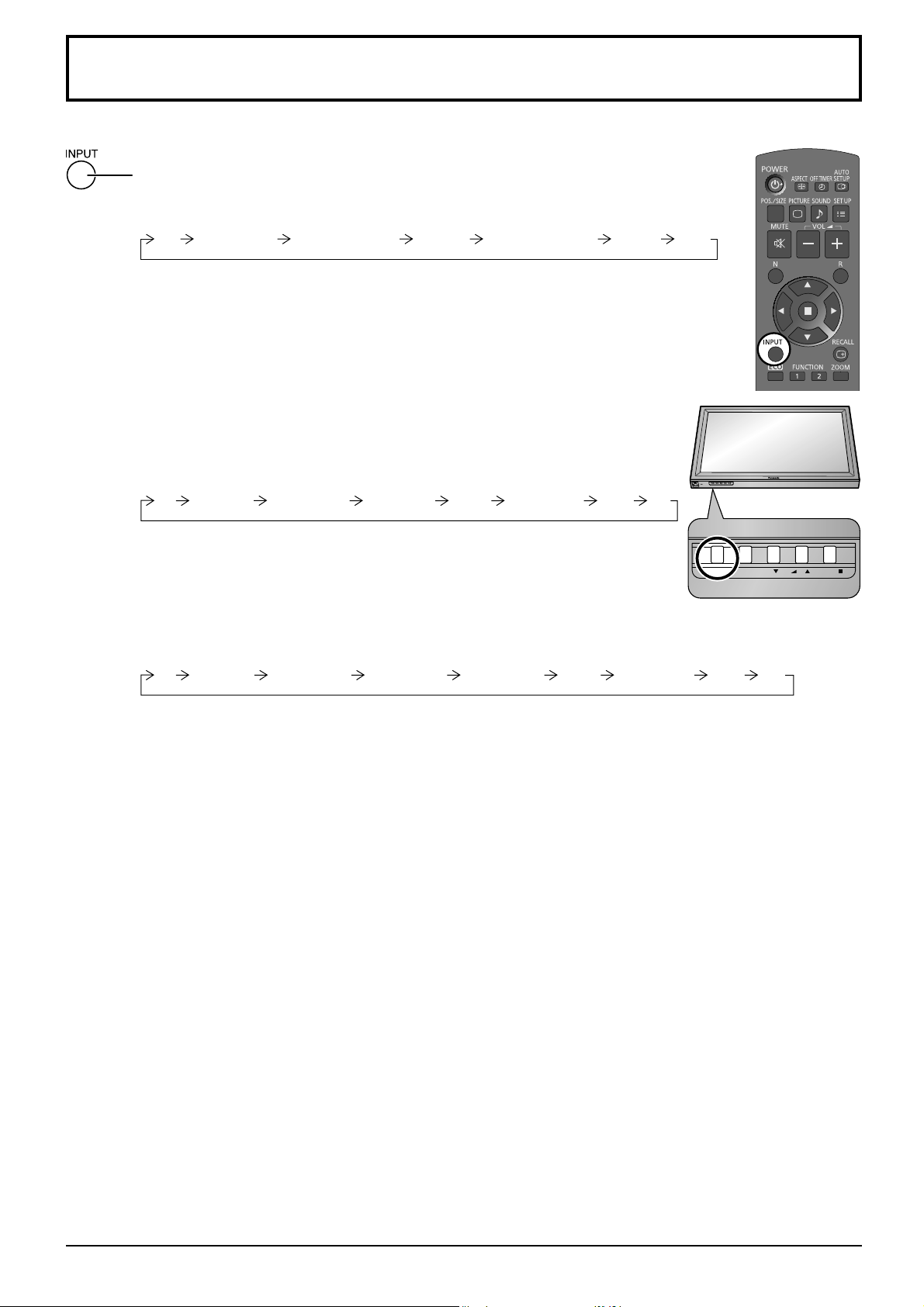
Selecting the input signal
INPUT MENU ENTER/+/VOL-/
Press to select the input signal to be played back from the equipment which has been
connected to the Plasma Display.
Input signals will change as follows:
PC COMPONENT* DVINETWORK HDMIVIDEO
PC: PC input terminal in PC IN.
NETWORK: Network input terminal in LAN or WIRELESS MODULE.
WHITEBOARD: WhiteBoard mode.
VIDEO: Video input terminal in AV IN (VIDEO).
COMPONENT*: Component or RGB input terminal in COMPONENT/RGB IN.
HDMI: HDMI input terminal in AV IN (HDMI).
DVI: DVI input terminal in DVI-D IN.
* “COMPONENT” may be displayed as “RGB” depending on the setting of
“Component/RGB-in select”. (see page 46)
WHITEBOARD
This mode can be selected when the “WHITEBOARD function” is
“On”. (see page 34)
When an optional Terminal Board is installed:
PC VIDEO HDMI DVINETWORK COMPONENTSLOT INPUT
SLOT INPUT: Input terminal in Terminal Board
Note:
When a Terminal Board incompatible with the Plasma Display is installed,
“Non-Compatible Function Board” is displayed.
When a Terminal Board with dual input terminals is installed:
PC VIDEO HDMI DVINETWORK COMPONENTSLOT INPUT A SLOT INPUT B
SLOT INPUT A, SLOT INPUT B: Dual input terminal in Terminal Board.
Notes:
• Selecting is also possible by pressing the INPUT button on the unit.
• Outputs the sound as set in “Audio input select” in the Options menu. (see page 55)
• Select to match the signals from the source connected to the component/RGB input terminals. (see page 46)
• Image retention (image lag) may occur on the plasma display panel when a still picture is kept on the panel for an
extended period. The function that darkens the screen slightly is activated to prevent image retention (see page 58),
but this function is not the perfect solution to image retention.
WHITEBOARD
WHITEBOARD
INPUT MENU ENTER/+/VOL-/
16
Page 17
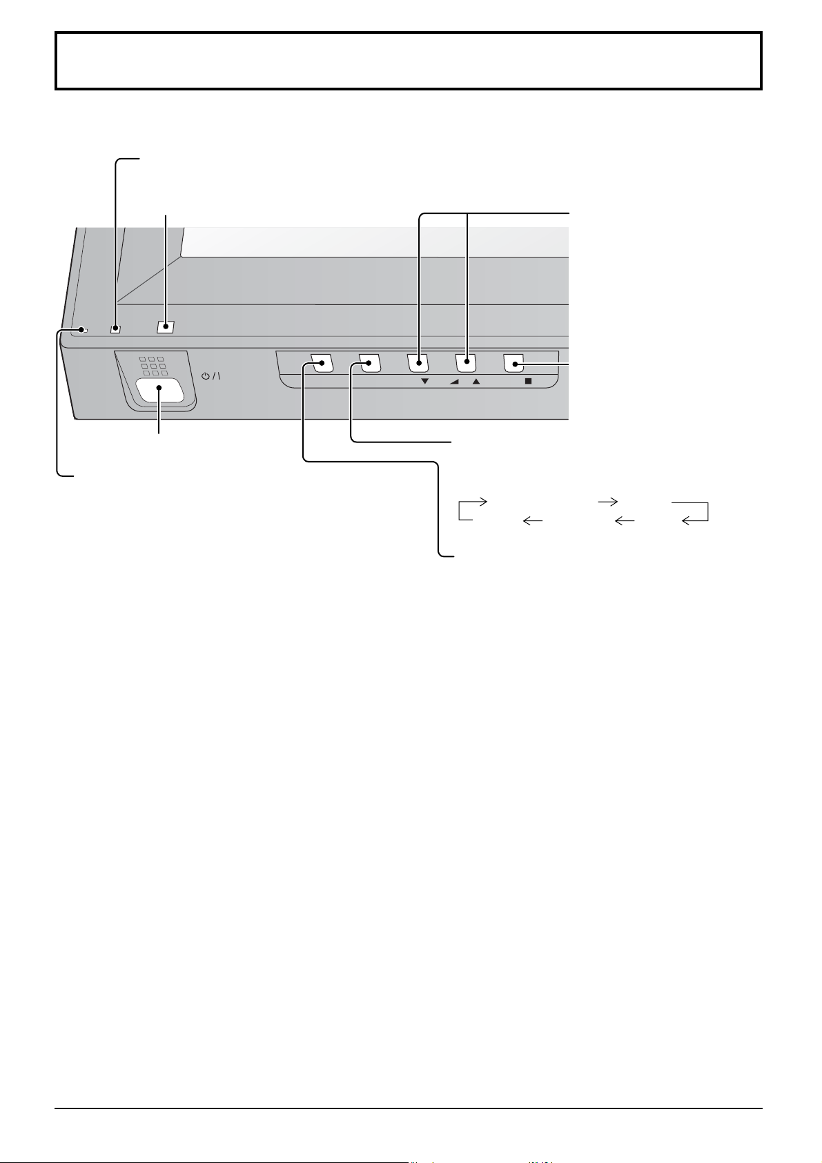
Basic Controls
INPUT MENU ENTER/
+
/VOL
-
/
Main Unit
Brightness Sensor
Detects the brightness in the viewing environment
Remote control sensor
Main Power On / Off Switch
Power Indicator
The Power Indicator will light.
• Power-OFF .... Indicator not illuminated (The unit will
still consume some power as long as
the power cord is still inserted into the
wall outlet.)
• Standby ........ Red
Orange (When “Slot power” is set to
“On” and Terminal Board is installed.
See page 52)
Orange (Depending on the type of the function board installed, when the power is supplied to
the slot)
Orange (When “Control I/F Select” is set to “LAN” or “WEB Control” is set to “On”. Refer to
“Operating Instructions, Network Operations”)
Orange (When “Quick WHITEBOARD Launch” is set to “On”. See page 34)
Orange (When “Standby pen charging mode” is set to “On” or “On[4hrs]”. See page 35)
• Power-ON ...... Green
• PC Power management (DPMS)
......................... Orange (With PC input signal. See page 42)
• DVI-D Power management
......................... Orange (With DVI input signal. See page 42)
Volume Adjustment
Volume Up “+” Down “–”
When the menu screen is
displayed:
“+” : press to move the cursor up
“–” :
press to move the cursor down
(see page 22)
Enter / Aspect button
(see page 19, 22)
MENU Screen ON / OFF
Each time the MENU button is pressed, the menu
screen will switch. (see page 22)
Normal Viewing Picture
Sound Pos./Size Setup
INPUT button
(INPUT signal selection)
(see page 16)
17
Page 18
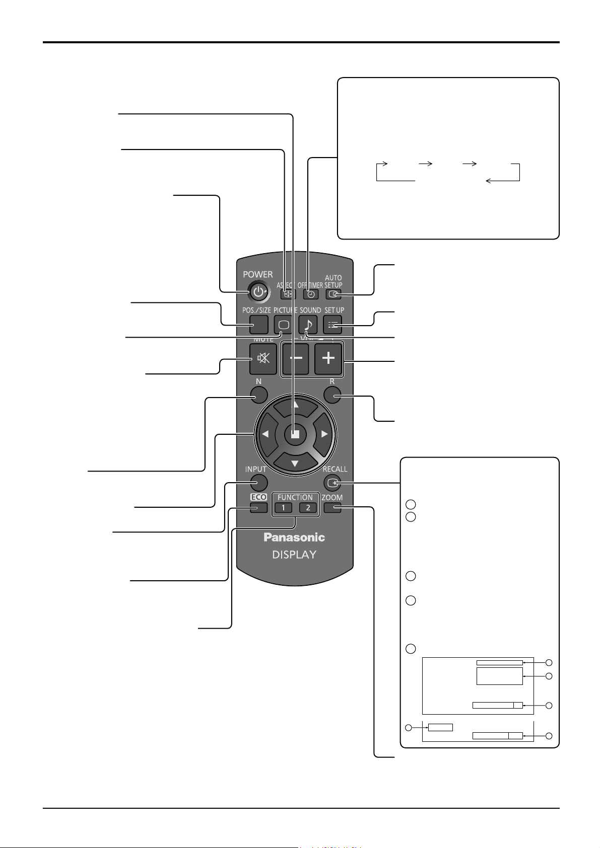
Basic Controls
Remote Control Transmitter
ACTION button
Press to make selections.
ASPECT button
Press to adjust the aspect.
(see page 19)
Standby (ON / OFF) button
The Plasma Display must fi rst be
plugged into the wall outlet and turned
on at the power switch (see page 14).
Press this button to turn the Plasma
Display On, from Standby mode.
Press it again to turn the Plasma
Display Off to Standby mode.
POS./SIZE button
(see page 23)
OFF TIMER button
The Plasma Display can be preset to switch to
stand-by after a fi xed period. The setting changes
to 30 minutes, 60 minutes, 90 minutes and 0
minutes (off timer cancelled) each time the button
is pressed.
30 min 60 min
90 min
0 min (Cancel)
When three minutes remain, “Off timer 3 min”
will fl ash.
The off timer is cancelled if a power interruption
occurs.
AUTO SETUP button
Automatically adjusts the position/
size of the screen. (see page 23)
SET UP button (see page 32)
PICTURE button
(see page 26)
Sound mute On / Off
Press this button to mute the
sound.
Press again to reactivate sound.
Sound is also reactivated when
power is turned off or volume level
is changed.
N button
(see page 25, 26, 27, 31)
POSITION buttons
INPUT button
Press to select Input signal
sequentially. (see page 16)
ECO MODE (ECO)
Press to change the ECO MODE
setup status. (see page 42)
FUNCTION buttons (FUNCTION)
(see page 44)
SOUND button (see page 31)
Volume Adjustment
Press the Volume Up “+” or Down “–”
button to increase or decrease the
sound volume level.
R button (see page 22)
Press the R button to return to
previous menu screen.
RECALL button
Press the “RECALL” button to display
the current system status.
Input label
1
Aspect mode (see page 19)
2
Audio input (see page 55)
Profi le name (see page 30)
NANODRIFT Saver operating
(see page 40)
Touch Pen mode On/Off
3
(see page 34)
Off timer
4
The off timer indicator is
displayed only when the off
timer has been set.
Clock display (see page 52)
5
PC
♪ COMPONENT
Memory name: MEMORY2
NANODRIFT
4:3
1
2
18
Touch-Pen
10:00
5
Off timer
On
90min
Digital Zoom (see page 20)
3
4
Page 19
ASPECT Controls
INPUT MENU ENTER/ +/ VOL -/
The Plasma Display will allow you to enjoy viewing the picture at its maximum size, including wide screen cinema
format picture.
Note:
Be aware that if you put the display in a public place for commercial purposes or a public showing
and then use the aspect mode select function to shrink or expand the picture, you may be violating
the copyright under copyright law. It is prohibited to show or alter the copyrighted materials of other
people for commercial purposes without the prior permission of the copyright holder.
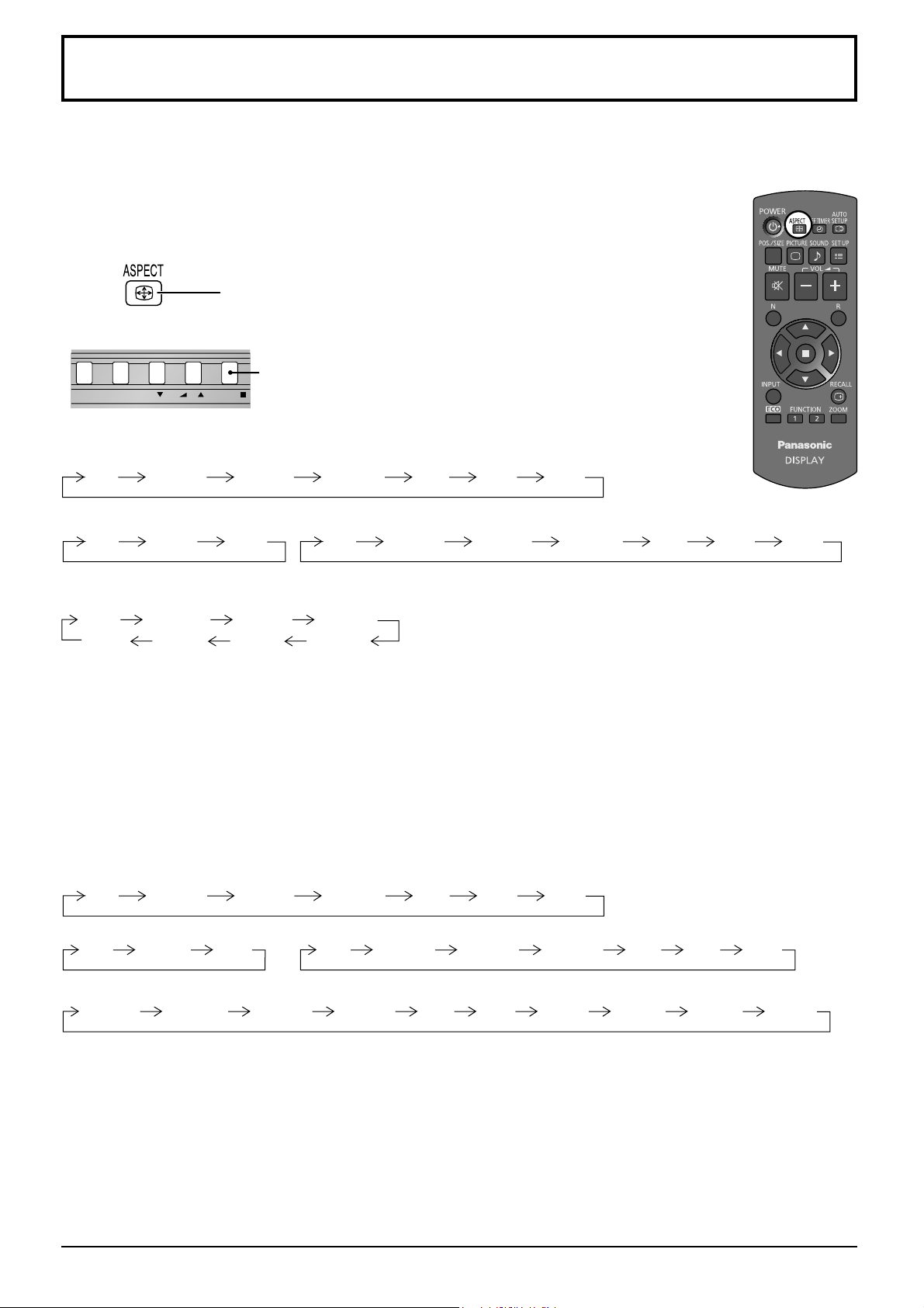
Press repeatedly to move through the aspect options:
For details about the aspect mode, please see “List of Aspect Modes” (page 59).
[from the unit]
The aspect mode changes each time the ENTER button is pressed.
For VIDEO (S VIDEO) signal input:
4:3 Zoom1 16:9Zoom2 Zoom3 14:9 Just
For PC signal input: For SD signal input (525 (480) / 60i • 60p, 625 (575) / 50i • 50p):
4:3 Zoom 16:9
4:3 Zoom1 16:9Zoom2 Zoom3 14:9 Just
For HD signal input [1125 (1080) / 60i • 50i • 60p • 50p • 24p • 25p • 30p • 24sF, 1250 (1080) / 50i,
750 (720) / 60p • 50p]:
4:3
[For Touch Pen mode]
The aspect is fi xed as “16:9” and you cannot switch.
Notes:
• The aspect mode is memorized separately for each input terminal.
• Do not allow the picture to be displayed in 4:3 mode for an extended period, as this can cause a permanent image
retention to remain on the Plasma Display Panel.
All Aspect mode
Set “All Aspect” to “On” in Options menu to enable the extended aspect mode (page 52). When All Aspect mode, the aspect
mode of pictures is switched as follows. For details about the aspect mode, please see “List of Aspect Modes”. (page 59)
For VIDEO (S VIDEO) signal input:
4:3 Zoom1 16:9Zoom2 Zoom3 14:9 Just
For PC signal input:
4:3 Zoom 16:9
For HD signal input [1125 (1080) / 60i • 50i • 60p • 50p • 24p • 25p • 30p • 24sF, 1250 (1080) / 50i, 750 (720) / 60p • 50p]:
4:3 Full Zoom1 16:9 Just1Zoom2 Zoom3 14:9 Just2 4:3 (1) 4:3 (2)
4:3 Full Zoom1
14:9Just
16:9
Zoom2
Zoom3
For SD signal input (525 (480) / 60i
4:3 Zoom1 16:9 JustZoom2 Zoom3 14:9
•
60p, 625 (575) / 50i
•
50p):
19
Page 20
Digital Zoom
INPUT MENU ENTER/ +/ VOL -/
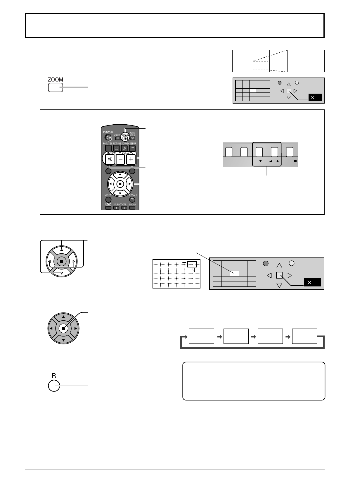
This displays an enlargement of the designated part of the displayed image.
Display the operation guide.
1
Press to access Digital Zoom.
The operation guide will be displayed.
During Digital Zoom, only the following buttons can be operated.
[Remote control]
Select the area of the image to be enlarged.
2
Press on the enlargement location to select.
Exit
1
OFF TIMER button
[Unit]
VOL button
MUTE button
VOL button
POSITION /
ACTION button
The cursor will move.
Select the magnifi cation required for the enlarged display.
3
Each time this is pressed, the magnifi cation factor changes.
This is shown in the image being displayed.
s1
Return to normal display (quit Digital Zoom).
4
Press to exit from the Digital Zoom.
Notes:
• When power goes OFF (including “Off Timer” operation), Digital Zoom terminates.
• The Digital Zoom function cannot be selected while in the following operation state:
When WHITEBOARD input.
When two screen display.
When Screensaver (except for Negative image) is running (see page 37)
• While Digital Zoom is in operation, “Adjusting Pos./Size” cannot be used.
Touch Pen mode during Digital Zoom
The electronic pen cannot be used while the image is
enlarged with Digital Zoom during Touch Pen mode.
The electronic pen can be used when Digital Zoom is
cancelled.
s2
s3
Exit
s4
2
2
20
Page 21
MULTI PIP
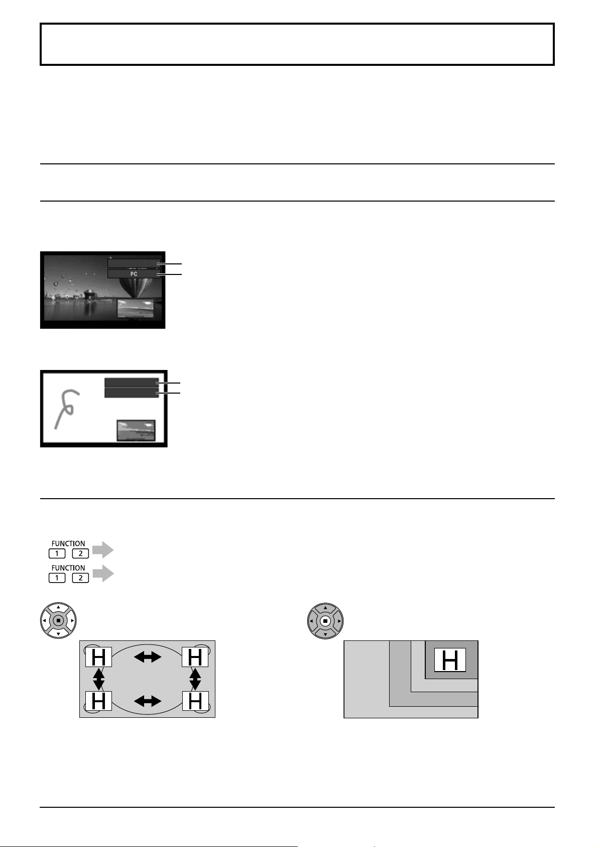
You can display two pictures, such as a video image and computer image, in a two-screen display.
Notes:
• If “Input lock” in Options menu is set to other than “Off”, two screen display function isn’t available (see page 51).
• 2k1k signals that are received with the Dual Link HD-SDI Terminal Board (TY-FB11DHD) cannot be displayed in
two-screen display.
MULTI PIP Settings
Set the functions and mode for two-screen display in “MULTI PIP Settings” in the Setup menu. (see page 36)
PIP Mode
There are two modes for two screen display:
Pic in Pic
Displays two input images combined.
SLOT INPUT
Pic in WHITEBOARD
Displays the built-in WhiteBoard with the other input image combined.
WHITEBOARD
PC
Note:
SD signal is displayed in 4:3 mode on the sub screen.
Main screen input
Sub screen input
Main screen is fi xed to WHITEBOARD.
Inputs supported for the sub screen: HDMI/DVI/COMPONENT/PC/VIDEO
Note:
SLOT INPUT and NETWORK cannot be displayed on the sub screen.
The following three system inputs are combined:
A SLOT INPUT/NETWORK
B HDMI/DVI/COMPONENT/PC
C VIDEO
Note:
Two screen display cannot be displayed with the same system
inputs such as HDMI―DVI combined.
Using Two Screen Display
Set “MULTI PIP” in “MULTI PIP Settings” to “On” (see page 36).
Two screen display appears.
Using the FUNCTION button
On/Off of “MULTI PIP” switches.
“MULTI PIP Settings” menu appears.
Note:
Please use the “Function Button Settings” to set the
FUNCTION button (see page 44).
Switching Sub Screen Position Changing the Size of Sub Screen
Press to switch the sub screen position. Press to change the size of the sub screen.
Note:
Alternatively, “Sub screen size” and “Sub screen position” in “MULTI PIP Settings” can be used for the same
operation (see page 36).
21
Page 22
On-Screen Menu Displays
Remote Control Unit
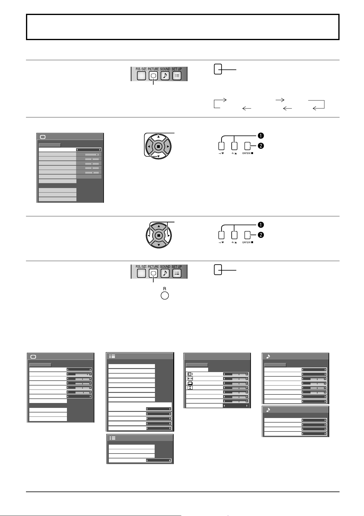
Display the menu screen.
1
Select the item.
2
Picture
Normal
Normalise
Picture Mode
Contrast
Brightness
Colour
Hue
Sharpness
White balance
Advanced settings
Memory save
Memory load
Memory edit
25
0
0
0
5
Normal
Normal
(Example: Picture menu)
Set.
3
Press to select.
(Example: Picture menu)
Select.
Set.
Press several times.
MENU
Each time the MENU button is pressed, the
menu screen will switch.
Normal Viewing Picture
Sound Pos./Size Setup
Select.
Press.
Adjust.
Press.
Exit the menu.
4
MENU
Press several times.
Press.
Press to return to the previous menu.
Menu display list
Note: Menu that cannot be adjusted is grayout. Adjustable menu changes depending on signal, input and menu setting.
Picture menu Setup menu Pos./Size menu Sound menu
RGB
Disable
30 S
5
Landscape
1/2
see page 23-25
)
2/2 Setup
Pos./Size
Normalise
Auto Setup
H-Pos
H-Size
V-Pos
V-Size
Dot Clock
Clock Phase
Clamp Position
1:1 Pixel Mode
Normal
Internal
Normal
0
0
0
0
Off
Main
Channel 1
Channel 1
Off
Off
1/2
2/2
Sound
Normal
Normalise
0
0
0
0
0
0
0
Off
Speaker
Sound Mode
Bass
Mid
Treble
Balance
Surround
Audio Out (PIP)
SDI Sound Output
Left Channel
Right Channel
Sound Out
Level Meter
see page 31
Picture
Normal
Normalise
Picture Mode
Contrast
Brightness
Colour
Hue
Sharpness
White balance
Advanced settings
Memory save
Memory load
Memory edit
see page 26-30
25
0
0
0
5
Normal
Normal
Setup
Touch-Pen Settings
MULTI PIP Settings
Signal
Screensaver
Extended life settings
ECO Mode settings
Input label
Function Button Settings
Component/RGB-in select
No activity power off
Menu Display Duration
OSD Brightness
OSD Language English (UK
On/Off Timer Setup
Day/Time Setup
Network Setup
Display orientation
see page 32-49
22
Page 23
Adjusting Pos./Size
1
2
3
4
Notes:
• Pos./Size cannot be adjusted with two screen display.
• Adjustment details are memorized separately for different input signal formats (Adjustments for component signals are
memorized for 525 (480) / 60i · 60p, 625 (575) / 50i · 50p, 1125 (1080) / 60i · 50i · 60p · 50p · 24p · 25p · 30p · 24sF,
1250 (1080) / 50i, 750 (720) / 60p · 50p each, and RGB/PC/Digital signals are memorized for each frequency.)
• If a “Cue” or “Rew” signal from a VCR or DVD player is received, the picture position will shift up or down. This picture
position movement cannot be controlled by the Picture Pos./Size function.
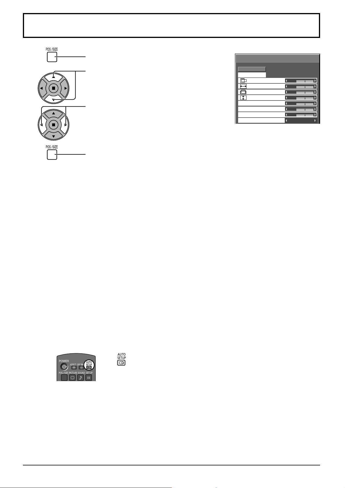
Press to display the Pos./Size menu.
Press to select the menu to adjust.
Press to adjust the menu.
Press to exit from adjust mode.
Pos./Size
Normalise
Auto Setup
H-Pos
H-Size
V-Pos
V-Size
Dot Clock
Clock Phase
Clamp Position
1:1 Pixel Mode
Note:
Unadjustable items are grayed
out.
Adjustable items differ depending
on the input signal and the
display mode.
Normal
0
0
0
0
0
0
0
Off
Auto Setup
When inputting a PC signal as an example, “H-Pos/V-Pos”, “H-Size/V-Size”, “Dot Clock” and “Clock
Phase” are automatically corrected.
This setting is enabled under the following conditions:
•
When inputting an analog signal (Component/PC):
This setting is enabled if “Component/RGB-in select” (see page 46) in Setup menu is “RGB”.
• When inputting a digital signal (HDMI/DVI):
A PC format signal enables this setting.
When the signal is not PC format, this setting is enabled only if “Over Scan” (see page 24) is “Off” or
“1:1 Pixel Mode” (see page 25) is “On”. “H-Size/V-Size” is not automatically adjusted.
This setting will be invalid and will not work under the following conditions:
• When NETWORK input is selected.
• When VIDEO signal input
• During two screen or Digital Zoom.
• Aspect is set to “Just”
• “Display size” in the Options menu (see page 51) is set to “On”
Using Remote Control
When on the remote control is pressed, “Auto Setup” will be executed.
When Auto Setup does not work, “Invalid” is displayed.
Auto mode
When the “Auto Setup“ is set to “Auto” in the Options menu (see page 52), automatic position adjustment starts:
• When the display power is turned ON.
• When the input signal is switched.
23
Page 24
Adjusting Pos./Size
Notes:
• If the dot clock frequency of an analog signal is 162 MHz or higher, “Dot Clock” and “Clock Phase”
cannot be automatically corrected.
• When digital signal input, Dot Clock and Clock Phase cannot be made.
• Auto Setup may not work when a cropped or dark image is input. In such case, switch to a bright image
with borders and other objects are clearly shown, and then try auto setup again.
• Depending on the signal, out of alignment may occur after Auto Setup. Carry out fi ne tuning for the
position/size as required.
• If Auto Setup cannot set properly for vertical frequency 60Hz XGA signal (1024×768@60Hz,
1280×768@60Hz, and 1366×768@60Hz), pre-selecting the individual signal in “XGA Mode” (see page
47) may results in correct Auto Setup.
• Auto Setup does not work well when a signal such as additional information is superimposed out of
valid image period or intervals between synchronizing and image signals are short, or for image signal
with tri-level synchronizing signal added.
• If Auto Setup cannot adjust correctly, select “Normalise” once and press ACTION ( ), then adjust
Pos./Size manually.
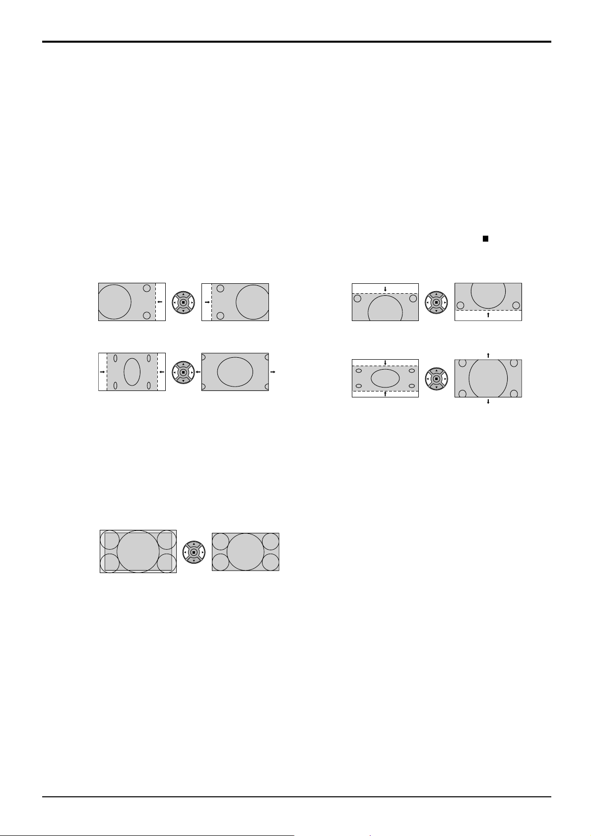
H-Pos Adjust the horizontal position. V-Pos Adjust the vertical position.
H-Size Adjust the horizontal size. V-Size Adjust the vertical size.
Dot Clock (During Component/PC input signal)
Periodic striped pattern interference (noise) may occur when a striped pattern is displayed. If this happens,
adjust so that any such noise is minimized.
Clock
Phase
Over scan Turn image over scan On/Off.
(During Component/PC input signal)
Eliminate the fl ickering and distortion.
Confi gurable signals are as follows:
525i, 525p, 625i, 625p, 750/60p, 750/50p (Component Video, RGB, DVI, SDI, HDMI)
On Off
Notes:
• When “Off” is set, “H-Size” and “V-Size” cannot be adjusted.
• When the “Display size” is set to “On” in the Options menu, this setting will be invalid. (see page 51)
24
Page 25
Adjusting Pos./Size
Clamp Position (During Component/PC input signal)
Adjusts the clamp position when black parts of the image have no detail due to underexposure
or are tinged with green.
Optimum value for Clamp Position adjustment
When black parts have no detail due to underexposure (blackout)
→ Value that causes least blackout is the optimum.
When black parts are tinged with green
→ Value that cancels the greenishness without causing blackout is the optimum.
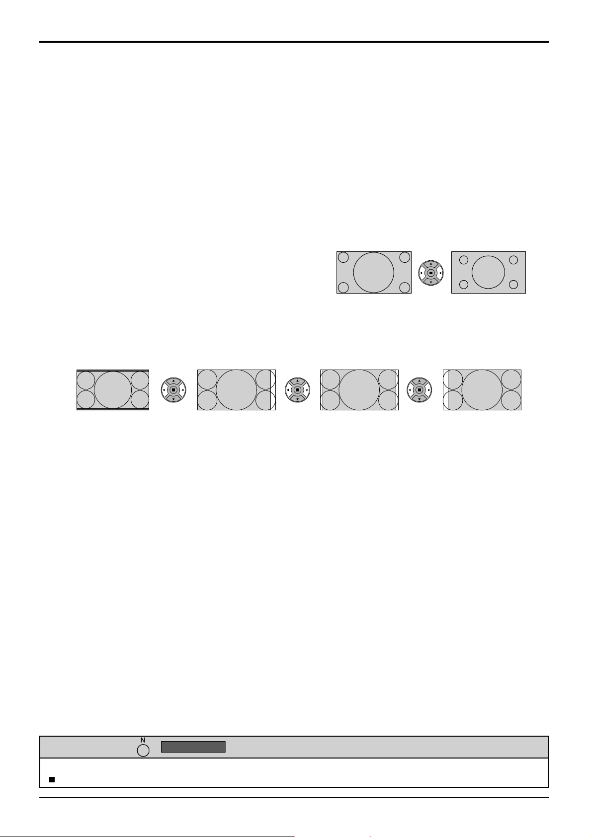
1:1 Pixel Mode Adjusts the display size when 1125i, 1125p or 1250i signal is input.
Notes:
• Select On when you would like to replay 1920 × 1080 input signal.
• Applicable input signal;
1125 (1080) / 50i · 60i · 24sF · 24p · 25p · 30p · 50p · 60p, 1250 (1080) / 50i
• Select Off when fl ickering is shown around the image.
• H-Size and V-Size cannot be adjusted when On is selected.
Off On
1:1 Pixel Mode
(2k1k)
(For 2k1k signals)
Off On (Left) On (Center) On (Right)
Note:
2k1k signals can only be received when the Dual Link HD-SDI Terminal Board (TY-FB11DHD) is installed.
When the input signal is a 2k1k signal (2048 × 1080 / 24p, 2048 × 1080 / 24sF), the display size
is adjusted as follows.
Helpful Hint ( /
While the Pos./Size display is active, if either the N button on the remote control is pressed at any time or the ACTION
( ) button is pressed during “Normalise”, then all adjustment values are returned to the factory settings.
Normalise
Normalisation)
25
Page 26
Picture Adjustments
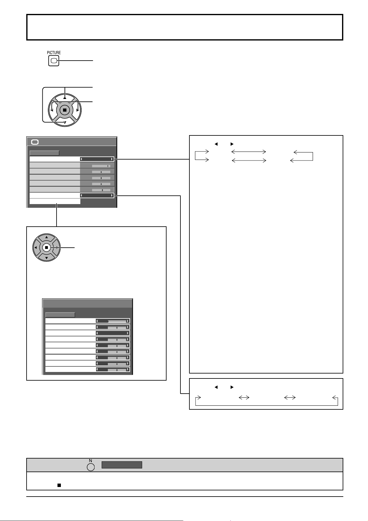
1
Select to adjust each item.
2
Press to display the Picture menu.
Press to select the menu to adjust.
Select the desired level by looking at the picture behind the menu.
Note:
Menu that cannot be adjusted is grayout. Adjustable menu changes depending on signal,
input and menu setting.
Picture
Normalise
Picture Mode
Contrast
Brightness
Colour
Hue
Sharpness
White balance
Advanced settings
Normal
Normal
25
0
0
0
5
Normal
Press to enter
Advanced settings.
Advanced settings
Enables fi ne picture adjustment at a professional
level (see next page).
Advanced settings
Normalise
Black extension
Input level
Gamma
W/B High R
W/B High G
W/B High B
W/B Low R
W/B Low G
W/B Low B
Normal
0
0
2.2
0
0
0
0
0
0
Press “ ” or “ ” button to switch between modes.
Normal
Monitor
Dynamic
Cinema
Normal
For viewing in standard (evening lighting) environments.
This menu selects the normal levels of Brightness
and Contrast.
Dynamic
For viewing in brighter environments.
This menu selects higher than normal levels of
Brightness and Contrast.
Cinema
For use in viewing tone-focused pictures with
brightness reduced.
Monitor
For use when creating broadcast or movie content.
With this picture, even if the overall average picture
level (APL) changes, the brightness of areas with
the same signal level does not change.
Picture Mode during Touch Pen mode
Only “Normal” or “Dynamic” can be selected in
Picture Mode during Touch Pen mode.
Notes:
• When “Monitor” is selected in Picture Mode, the
following menu items cannot be set.
Extended life settings: Peak limit (see page 40)
•
If you would like to change the picture and colour of
the selected Picture menu to something else, adjust
using the items in the Picture menu. (see next page)
Press “ ” or “ ” button to switch between modes.
Normal (9300K) Cool (11500K) Warm (6500K)
Helpful Hint ( /
Normalise
Normalisation)
While the “Picture” menu is displayed, if either the N button on the remote control is pressed at any time or the
ACTION ( ) button is pressed during “Normalise”, then all adjustment values are returned to the factory settings.
26
Page 27
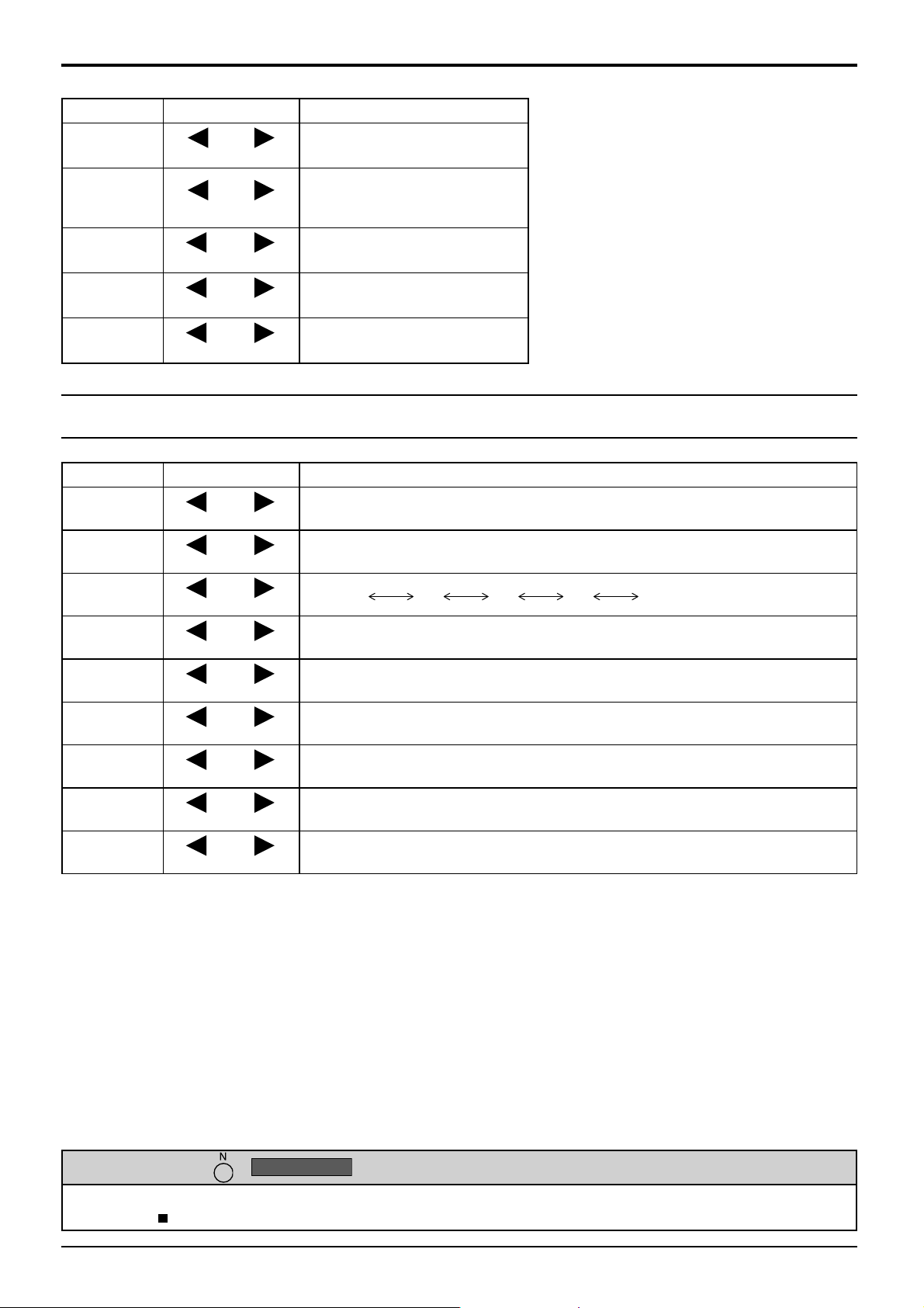
Picture Adjustments
Item Effect Adjustments
Contrast
Less More
Selects the proper brightness
and density for the room.
Adjusts for easier viewing of
Brightness
Colour
Hue
Sharpness
Darker Brighter
Less More
Reddish Greenish
Less More
dark pictures such as night
scenes and black hair.
Adjusts colour saturation.
Adjusts for nice skin colour.
Adjusts picture sharpness.
Notes:
• You can change the level of each function
• The setting details for Normal, Dynamic,
• In Contrast, there is not a noticeable change
Advanced settings
Item Effect Details
Black
extension
Input level
Less More
Less More
Adjusts the dark shades of the image in gradation.
Adjustment of parts which are extremely bright and hard to see.
(Contrast, Brightness, Colour, Hue, Sharpness)
for each Picture Mode.
Cinema and Monitor respectively are memorized
separately for each input terminal.
even when contrast is increased with a bright
picture or reduced with a dark picture.
Gamma
W/B High
R
W/B High
G
W/B High
B
W/B Low R
W/B Low G
W/B Low B
Down Up
Less More
Less More
Less More
Less More
Less More
Less More
S Curve 2.0 2.2 2.4 2.6
Adjusts the white balance for light red areas.
Adjusts the white balance for light green areas.
Adjusts the white balance for light blue areas.
Adjusts the white balance for dark red areas.
Adjusts the white balance for dark green areas.
Adjusts the white balance for dark blue areas.
Notes:
• Advanced settings cannot be adjusted with two screen display.
• Carry out “W/B” adjustment as follows.
Adjust the white balance of the bright sections using the “W/B High R”, “W/B High G” and “W/B High B” settings.
1.
2. Adjust the white balance of the dark sections using the “W/B Low R”
, “W/B Low G”
and “W/B Low B” settings.
3. Repeat steps 1 and 2 to adjust.
Steps 1 and 2 affect each other’s settings, so repeat each step in turn to make the adjustment.
• The adjustment values are memorized separately for each input terminal.
• The adjustment range values should be used as an adjustment reference.
Helpful Hint ( /
Normalise
Normalisation)
On the remote control unit, while the “Advanced settings” menu is displayed, if either the N button is pressed at any time or
the ACTION ( ) button is pressed during “Normalise”, then all adjustment values are returned to the factory settings.
27
Page 28

Picture Profi les
Up to 8 combinations of picture adjustment values (in the Picture menu and Advanced settings) can be stored in the
display memory as profi les and applied as needed, for a convenient way to enjoy your preferred picture settings.
Picture
Normalise
Picture Mode
Contrast
Brightness
Colour
Hue
Sharpness
White balance
Advanced settings
Normal
Memory save
Memory load
Memory edit
Dynamic
18
0
0
0
3
Normal
Save profi les(page 29)
Load profi les(page 30)
Edit profi les(page 30)
Picture
Normalise
Picture Mode
Contrast
Brightness
Colour
Hue
Sharpness
White balance
Advanced settings
Normal
Normal
25
0
0
0
5
Normal
Edit the profi le
Delete or rename
the profi le
Original picture
Picture
Normalise
Picture Mode
Contrast
Brightness
Colour
Hue
Sharpness
White balance
Advanced settings
Normal
0
0
0
0
0
Normal
Normal
MY PICTURE
MEMORY2
MEMORY3
MEMORY4
MEMORY8
Load the profi le
Save profi les
MEMORY1
MEMORY2
MEMORY3
MEMORY4
MEMORY8
Custom picture
Picture
Normalise
Picture Mode
Contrast
Brightness
Colour
Hue
Sharpness
White balance
Advanced settings
Normal
Save the picture
adjustment values in
the MEMORY1 profi le
Apply the MEMORY1
profi le
Normal
25
0
0
0
5
Normal
28
Page 29
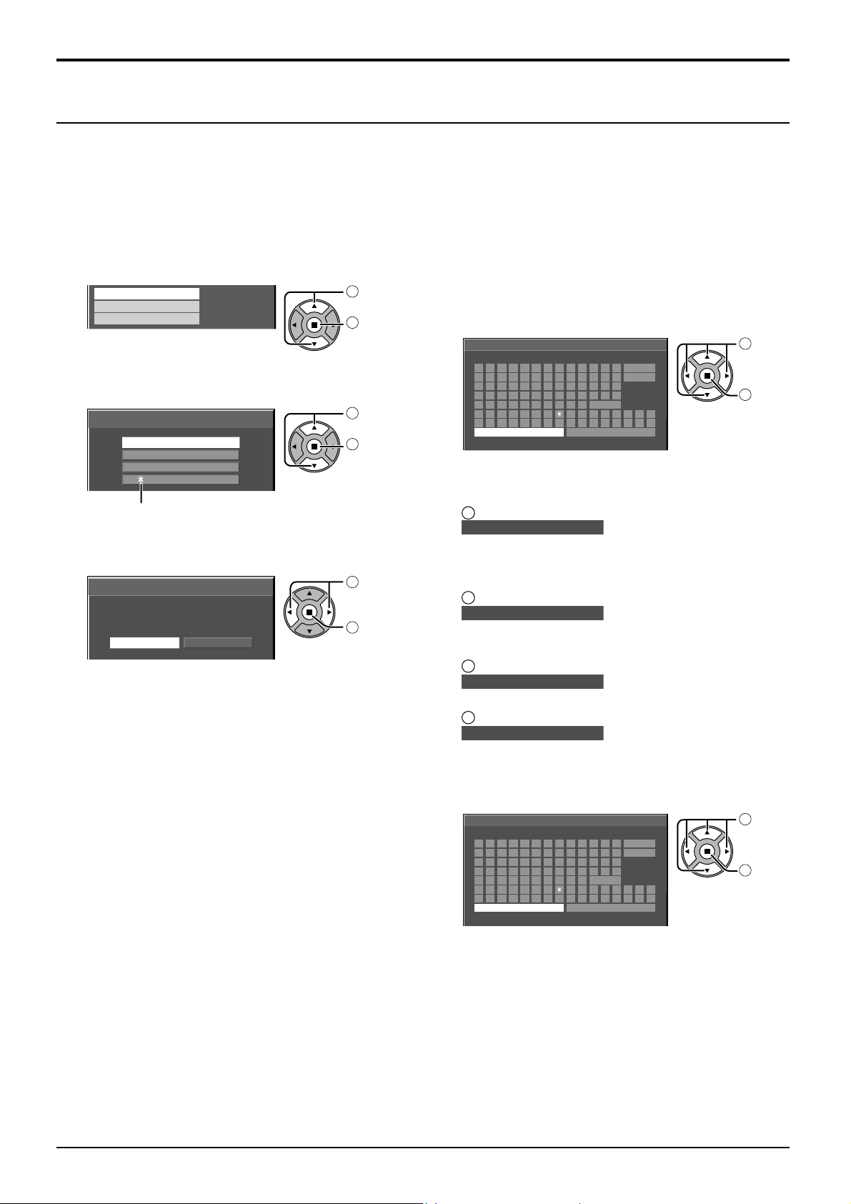
Saving profi les
Follow these steps to save picture adjustment values as profi les.
Note:
When the settings are locked in “Extended life settings”, profi les cannot be saved.
Picture Profi les
Specify the picture quality in the Picture menu and
1
Advanced settings. (see page 26, 27)
In the Picture menu, select “Memory save”.
2
3
Memory save
Memory load
Memory edit
Select a profi le name for saving the picture adjustment
values.
Memory save
[
]
MEMORY1
1.
[
]
MEMORY2
2.
[
]
3.
MEMORY3
[
]
4.
MEMORY4
1
2
1
2
“∗ ” appears for a profile in which the picture
adjustments have already been saved.
Select “Ok”.
4
Memory save
Save the adjusted value in ”MEMORY1”
Ok
Cancel
1
2
select
access
select
set
select
set
Enter a name for the profi le.
5
[Entering profi le names]
Profi le names can be up to 40 characters.
To enter text, select characters in the on-screen
keyboard.
Edit the default profile name in the text box as
desired.
Memory name input
B C D E F G H I J K L M All delete
A
N O P Q R S T U V W X Y Z Delete
abcdef ghi jk lm
nopqr s t uvwxyz
0123456789
!”#$%&’ +–/=?
_` |~<>( ) [ ] {} ,
MEMORY1
Ok
█
Space
@\ ˆ
.;:
Cancel
Example: Specifying “MY PICTURE”
Select “All delete”.
1
█
MEMORY1
All text is deleted.
To delete individual characters, select “Delete”.
2
Select “M”.
█
M
Repeat this process to enter the next character.
3
Select “Y”.
█
MY
select
1
set
2
4
Select “Space”.
█
MY
When you fi nished entering the profi le name, select
6
“Ok”.
To cancel saving the profi le, select “Cancel”.
Memory name input
A
B C D E F G H I J K L M All delete
N O P Q R S T U V W X Y Z Delete
abcdef ghi jk lm
nopqr s t uvwxyz
0123456789
!”#$%&’ +–/=?
_` |~<>( ) [ ] {} ,
MY PICTURE
Ok
█
Space
@\ ˆ
.;:
Cancel
select
1
set
2
29
Page 30
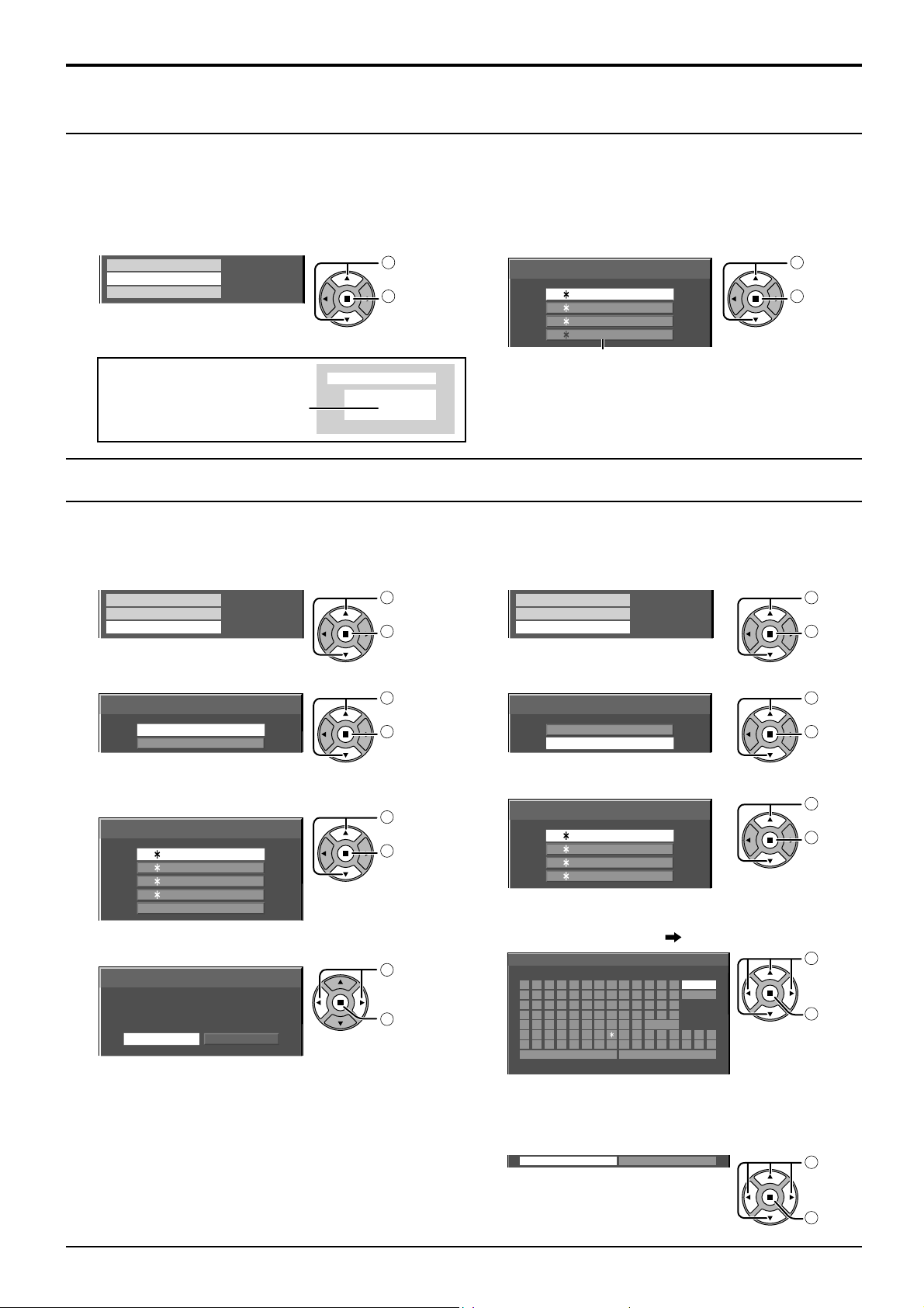
Picture Profi les
Loading profi les
Load profi les and apply the picture adjustment values to the display as follows.
Notes:
•
Loaded profi les are stored in memory according to the selected input terminal. (see page 16)
• When the settings are locked in “Extended life settings”, profi les cannot be loaded.
In the Picture menu, select “Memory load”.
1
Memory save
Memory load
Memory edit
select
1
access
2
Select the profi le to load.
2
Memory load
[ ]
MEMORY1
1.
[
]
.
MEMORY2
2
[
]
3.
MEMORY3
[
]
4.
MEMORY4
While in Touch Pen mode, a profi le(s), whose
“Picture Mode” is set to “Cinema” or “Monitor”, is
grayed out and cannot be selected.
When profi le is being loaded,
PC
Memory name: MEMORY2
16:9
NANODRIFT
profi le name is displayed.
Editing profi les
select
1
set
2
Delete or rename profi les as follows.
<Deleting profi les>
In the Picture menu, select “Memory edit”.
1
2
3
4
Memory save
Memory load
Memory edit
Select “Memory delete”.
Memory edit
Memory delete
Memory name change
Select the profi le to delete.
To delete all profi les, select “All delete”.
Memory delete
[
]
MEMORY1
1
.
[
]
MEMORY2
2.
[
]
3.
MEMORY3
[
]
4.
MEMORY4
All delete
Select “Ok”.
Memory delete
Delete the ”MEMORY1” data.
Ok
Cancel
select
1
access
2
select
1
set
2
select
1
set
2
select
1
set
2
<Renaming profi les>
In the Picture menu, select “Memory edit”.
1
2
3
4
Memory save
Memory load
Memory edit
Select “Memory name change”.
Memory edit
Memory delete
Memory name change
Select the profi le to rename.
Memory name change
[
]
MEMORY1
1.
[
]
MEMORY2
2.
[
]
3.
MEMORY3
[
]
4.
MEMORY4
Enter a name for the profi le.
Entering profi le names page 29
Memory name input
█
EMORY1M
ABCDEFGH I J K LM All delete
N O P Q R S T U V W X Y Z Delete
abcdef ghi jk lm
nopqr s t uvwxyz
0123456789
!”#$%&’ +–/=?
_` |~<>( ) [ ] {} ,
Ok
Space
Cancel
@\ ˆ
.;:
select
1
access
2
select
1
set
2
select
1
set
2
select
1
set
2
30
When you fi nished entering the profi le name, select
5
“Ok”.
To cancel renaming the profi le, select “Cancel”.
Ok
Cancel
select
1
set
2
Page 31
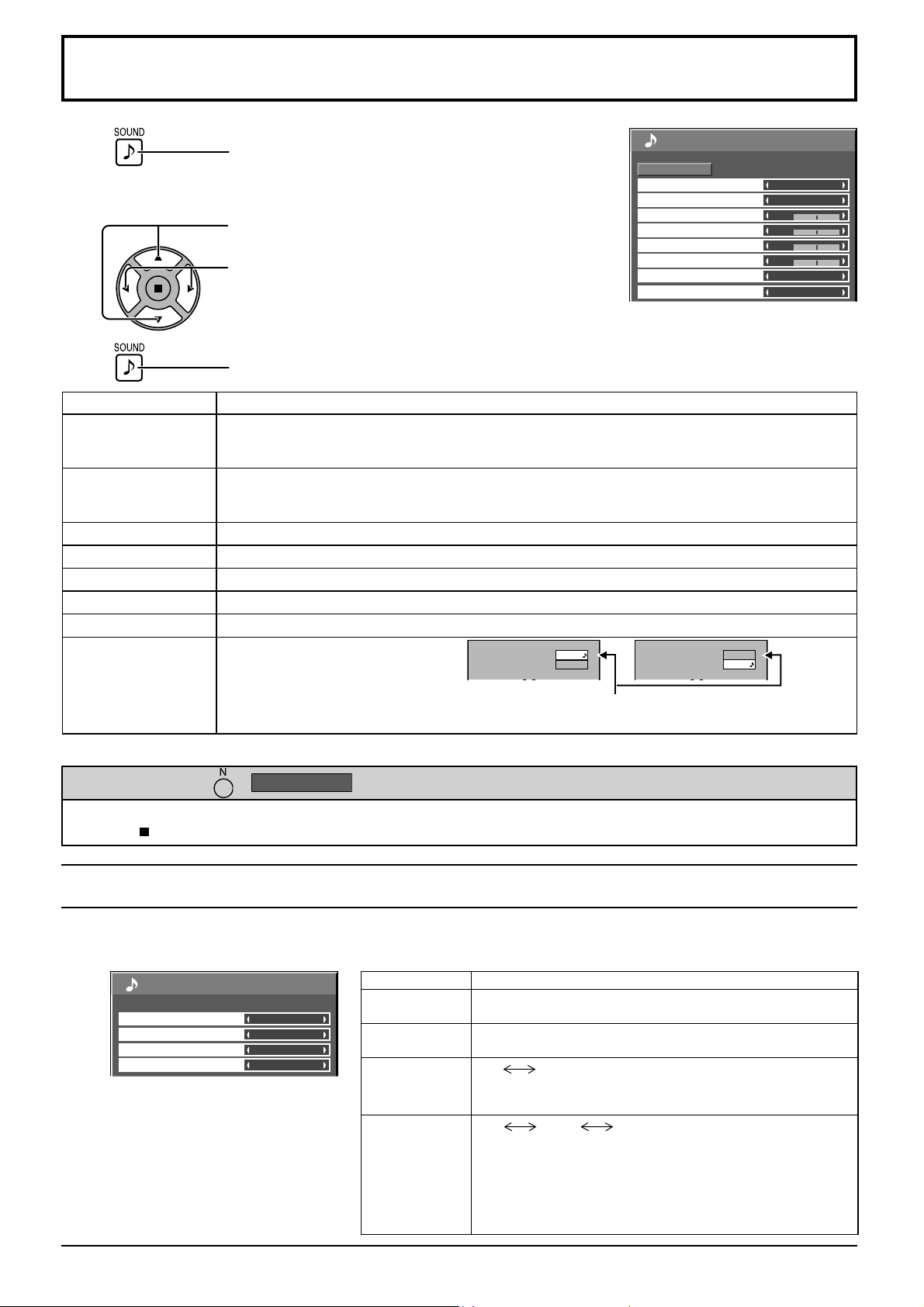
Sound Adjustment
1
Select to adjust each item.
2
3
Item
Speaker
Sound Mode
Bass Adjusts low pitch sounds.
Mid Adjusts normal sounds.
Treble Adjusts high pitch sounds.
Balance Adjusts left and right volumes.
Surround Select On or Off.
Audio Out (PIP)
Press to display the Sound menu.
Press to select the menu to adjust.
Select the desired level by listening to the sound.
Press to exit from adjust mode.
Details
Select the audio output.
Internal: Internal speakers
External: External speakers
Normal: Emits the original sound.
Dynamic: Accentuates sharp sound.
Clear: Attenuates human voice.
Main: Selects main picture sound.
Sub: Selects PIP frame sound.
VIDEO
PC
Sound
Normalise
Speaker
Sound Mode
Bass
Mid
Treble
Balance
Surround
Audio Out (PIP)
Musical note ♪ is displayed on right side of the audio
output screen label.
Note: Bass, Mid, Treble and Surround settings are memorized separately for each Sound Mode.
Normal
VIDEO
PC
1/2
Internal
Normal
0
0
0
0
Off
Main
Helpful Hint ( /
Normalise
Normalisation)
While the “Sound” menu is displayed, if either the N button on the remote control is pressed at any time or the
ACTION ( ) button is pressed during “Normalise”, then all adjustment values are returned to the factory settings.
SDI Sound Output
This menu is available only when selecting a slot that any of the following terminal boards is installed:
HD-SDI Terminal Board with audio (TY-FB10HD) or Dual Link HD-SDI Terminal Board (TY-FB11DHD)
SDI Sound Output
Left Channel
Right Channel
Sound Out
Level Meter
2/2
Channel 1
Channel 1
Off
Off
Note:
This menu is unavailable when two screen
display mode is active.
Item Details
Left Channel
Right Channel
Sound Out
Level Meter
Channel 1 to Channel 16
Selects left audio channel.
Channel 1 to Channel 16
Selects right audio channel.
On
On: Enables audio output.
Off: Disables audio output.
Off
Sets audio channels to show in the audio level meter.
8 channels are displayed in the audio level meter; 4 channels
each on both right and left sides of the display.
Off: Hides the audio level meter.
1-8ch: Displays the audio level meter (1-8ch)
9-16ch
Off
1-8ch 9-16ch
: Displays the audio level meter (9-16ch)
31
Page 32
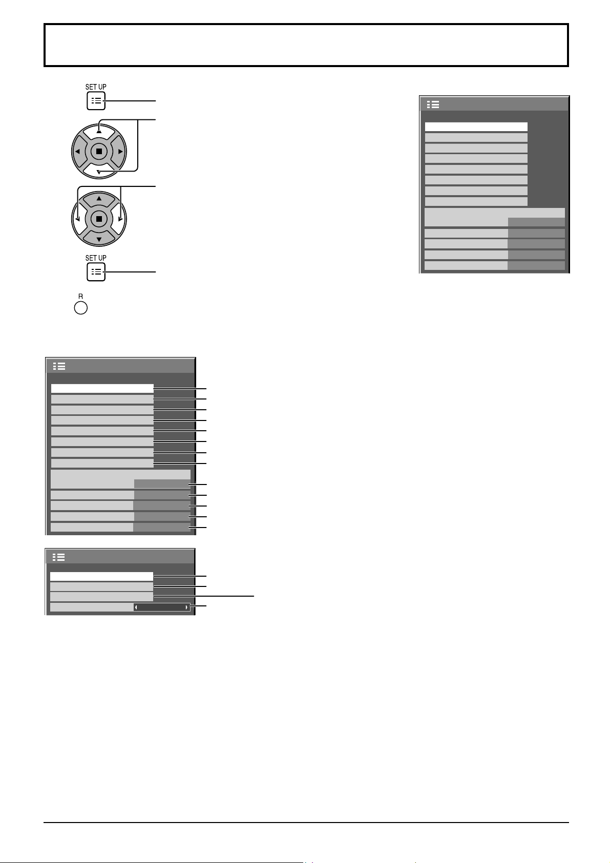
Setup menu
1
Press to display the Setup menu.
Press to select the menu to adjust.
2
3
Press to adjust the menu.
4
Press to return to the previous menu.
Setup menu screen
Setup
Touch-Pen Settings
MULTI PIP Settings
Signal
Screensaver
Extended life settings
ECO Mode settings
Input label
Function Button Settings
Component/RGB-in select
No activity power off
Menu Display Duration
OSD Brightness
OSD Language English (UK
Press to exit from adjust mode.
1/2
Page 34
Page 36
Page 47
Page 37
Page 39
Page 42
Page 43
Page 44
RGB
Disable
30 S
5
Page 46
Page 45
Page 45
Page 45
)
Page 45
Setup
Touch-Pen Settings
MULTI PIP Settings
Signal
Screensaver
Extended life settings
ECO Mode settings
Input label
Function Button Settings
Component/RGB-in select
RGB
No activity power off
Menu Display Duration
OSD Brightness
OSD Language English (UK
Disable
30 S
5
1/2
)
On/Off Timer Setup
Day/Time Setup
Network Setup
Display orientation
32
Landscape
2/2 Setup
Page 33
Page 33
Network Setup
Page 45
Set this to connect the Display to a computer via a network. For details
of PJLink and Network, refer to “Operating Instructions, Network
Operations”.
Page 33
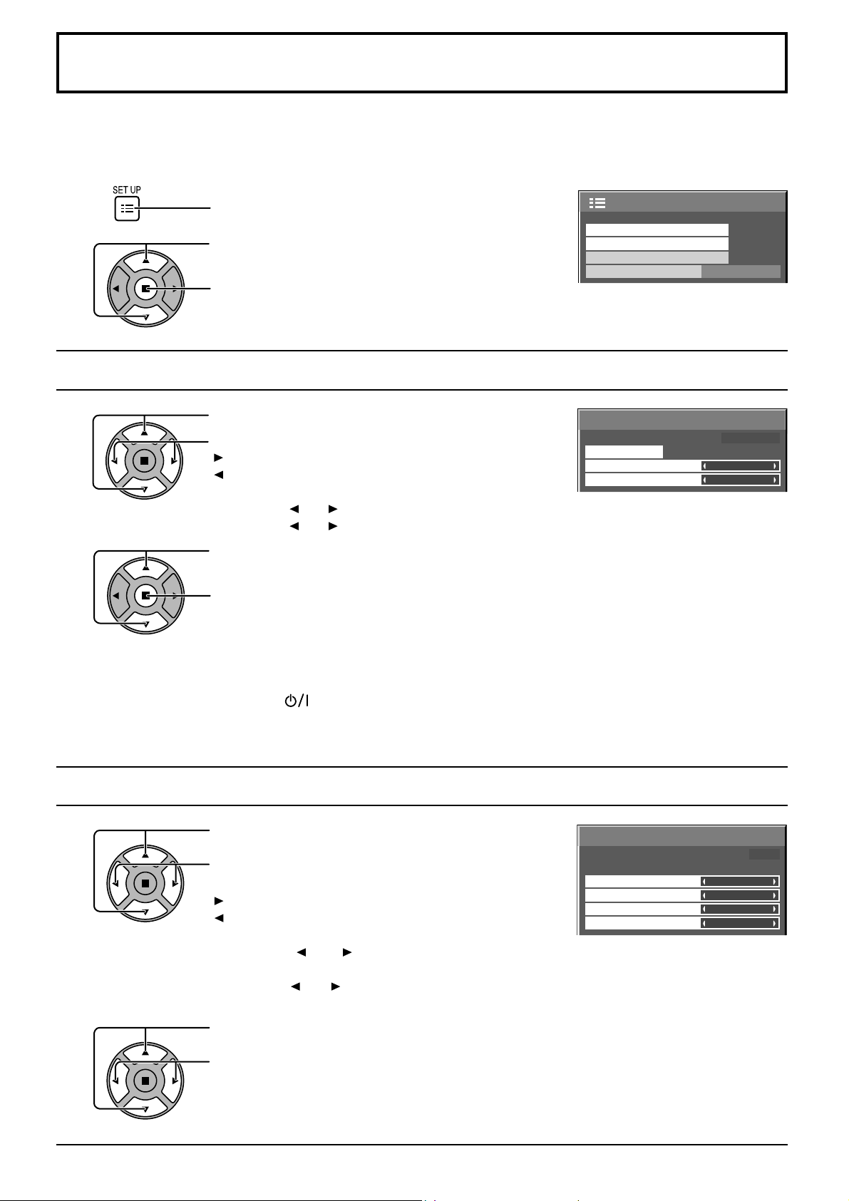
Day/Time Setup / On/Off Timer Setup
The timer can switch the Plasma Display On or Off.
Before attempting Timer Set, confi rm the Time and adjust if necessary.
Then set POWER ON Time / POWER OFF Time.
1
Press to display the Setup menu.
Press to select On/Off Timer Setup or Day/Time Setup.
2
Press to display the On/Off Timer Setup screen or
Day/Time Setup screen.
Day/Time Setup
1
Press to select Day or Time.
Press to setup Day or Time.
button: Forward
button: Back
Notes:
• Pressing “ ” or “ ” button once changes Time 1 minute.
• Pressing “ ” or “ ” button continuously changes Time by 15 minutes.
Press to select Set.
2
Press to store Day/Time Setup.
Notes:
• Set cannot be selected unless Time is set.
• Unless setting the present time other than “99:99”, “Day” and “Time” cannot be set.
• The settings of “Day” and “Time” are reset when leaving the display turned off for
about 7 days for the following reasons:
Pressing switch of the unit to turn off the display.
Disconnecting the AC cord.
Interruption of power supply.
On/Off Timer Setup
Day/Time Setup
Network Setup
Display orientation
Day/Time Setup
Set
Day
Time
2/2 Setup
Landscape
Time MON 99:99
MON
99:99
On/Off Timer Setup
1
Press to select
POWER ON Time / POWER OFF Time.
Press to setup
POWER ON Time / POWER OFF Time.
button: Forward
button: Back
Notes:
• Pressing “ ” or “ ” button once changes POWER ON Time / POWER OFF Time
1 minute.
• Pressing “ ” or “ ” button continuously changes POWER ON Time / POWER OFF Time
by 15 minutes.
Press to select POWER ON Function/POWER OFF Function.
2
Press to select On.
Note: Timer function will not work unless “Time” is set.
On/Off Timer Setup
POWER ON Function
POWER ON Time
POWER OFF Function
POWER OFF Time
Time 99:99
Off
0:00
Off
0:00
33
Page 34
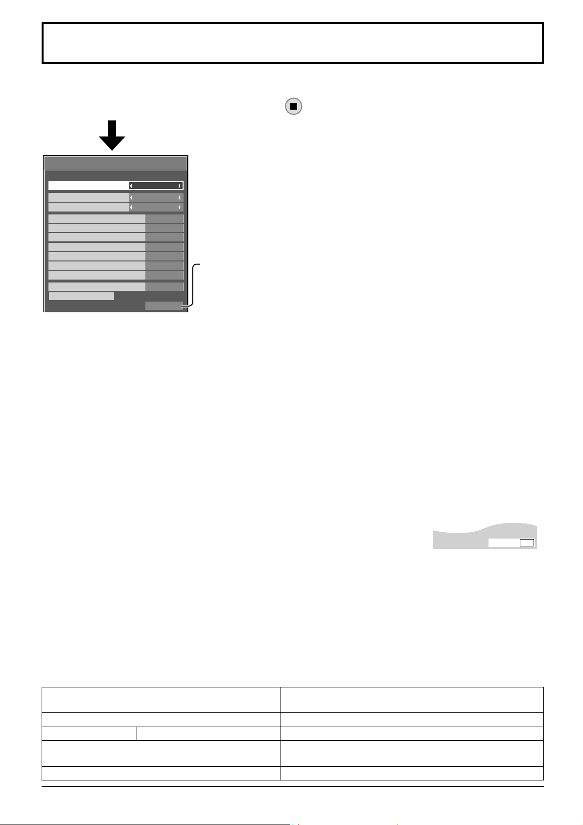
Touch-Pen Settings
Set Touch Pen mode.
Select “Touch-Pen Settings” in “Setup” menu and press
Touch-Pen Settings
Touch-Pen Mode
WHITEBOARD function
Quick WHITEBOARD launch
SLOT INPUT
VIDEO
COMPONENT
HDMI
DVI
PC
NETWORK
Standby pen charging mode
Pairing
Pen adapter status
Touch Only
Off
Off
Off
Off
Off
Off
Off
Off
Off
Off
Detected
When a Terminal Board with dual input terminals is installed, “SLOT INPUT” is
displayed as “SLOT INPUT A” and “SLOT INPUT B”.
Pen adapter status
Not detected: Electronic pen adapter is not connected.
Confi rming...: Immediately after connecting an electronic pen adapter and the
built-in WhiteBoard “Easy WhiteBoard” is starting up.
Detected: Electronic pen adapter is connected.
button.
Touch-Pen Mode
Select an appropriate setting for the function of the electronic pen used.
Touch Only: Contact-type Touch Pen
Touch & Remote: Contact-type Touch Pen and remote pointer
WHITEBOARD function
Sets the built-in WhiteBoard (WhiteBoard mode) function. When this is set to “On”, the built-in WhiteBoard function is
enabled and the WHITEBOARD input can be selected.
Quick WHITEBOARD launch
When this is set to “ON”, the built-in WhiteBoard will be in the standby mode when the plasma display is in the standby
mode (power OFF with remote control) and the start up is quicker.
Note:
This setting is automatically turned “On” and cannot be changed in the following cases.
When the power is supplied to the slot
When “Control I/F Select” is set to “LAN”
When “WEB Control” is set to “On”
When “Standby pen charging mode” is set to “On”
SLOT INPUT – NETWORK
Set “On” or “Off” for each input terminal.
If you switch to the input terminal that is set to “On”, the mode becomes Touch Pen
mode.
“Touch-Pen: On” is displayed in Touch Pen mode.
Touch-Pen
On
Notes:
• The picture quality changes according to the settings of “Touch-Pen Mode” and On/Off state of each input
terminal.
• The electronic pen cannot be used during Digital Zoom. (see page 20)
• When using the electronic pen, adjust “Pos./Size” so that the screen of the computer can be correctly displayed.
(see page 23)
Setting the Remote Control
You can also turn Touch Pen mode On/Off with the FUNCTION buttons on the remote control. (see page 44)
In Touch Pen mode, the menus and functions are restricted as follows.
Pos./Size menu
Picture menu
Setup menu Extended life settings
Options menu
ASPECT Controls
1:1 Pixel Mode: On
Over scan: Off
Picture Mode: “Normal” or “Dynamic” only. (see page 26)
Picture Mode: “Normal” or “Dynamic” only. (see page 39)
Display size: Unavailable
Rotate: Unavailable
16:9
34
Page 35
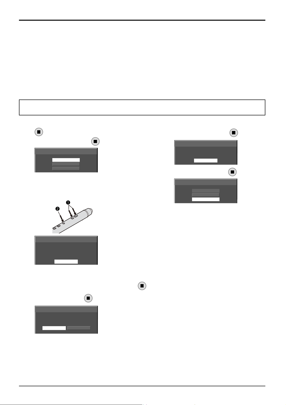
Touch-Pen Settings
Standby pen charging mode
Sets the power supply for the electronic pen charging terminal (CHARGE, MEMORY/(CHARGE)) in the standby mode
(power OFF with remote control).
Off: Turns off the charging terminal power in the standby mode.
On[4hrs]: Turns ON the charging terminal power for 4 hours after entering standby mode.
On: Leaves the charging terminal power ON in standby mode so that the pen can be charged.
Pairing
Registers an electronic pen to electronic pen adapter.
Up to four electronic pens can be registered for an electronic pen adapter.
For the details of the pairing, please refer to “Operating Instructions, Electronic Pen Operations”.
Note:
Make sure the electronic pen adapter is connected to the display.
If no electronic pen has been registered, the screen of procedure 3 appears fi rst. Follow the instructions
on the screen to register an electronic pen.
1
2
3
Select “Pairing” in “Touch-Pen Settings” and press
button.
Select “Pairing” and press button.
Pairing Tool
Pairing
Unpairing All
Close
While pressing both the remote drawing and the remote
clearing buttons of the electronic pen, press the Power
switch.
To cancel the paring, select “Cancel”.
Pairing in progress
Set the electronic pen that you want to pair as
pair-enabled and then move it closer to the
electronic pen adapter. For details, refer to the
procedure for registering electronic pens in the
operating instructions for the electronic pen.
Cancel
4
5
When the electronic pen paring is completed,
select “Return” and press button.
Pairing Tool
Pairing was successful.
Return
Select “Close” and press button.
Pairing Tool
Pairing
Unpairing All
Close
[Unpairing]
Unpairs all paired electronic pens.
1
2
Select “Unpairing All” in “Pairing Tool” and press button.
Select “Yes” and press button.
Pairing Tool
Do you want to cancel all pairings?
Yes
No
35
Page 36
MULTI PIP Settings
Set the two screen display function.
Two screen display function MULTI PIP (page 21)
Select “MULTI PIP Settings” in “Setup” menu and press button.
MULTI PIP Settings
MULTI PIP
PIP Mode
Main input
Sub input
Sub screen size
Sub screen position
Swap
On
Pic in Pic
COMPONENT
VIDEO
1
Lower right
MULTI PIP
Set this “ON” to have two screen display. Various settings such as “PIP Mode” can be set.
PIP Mode
Sets the two screen display mode.
Pic in Pic: Displays two input images combined.
Pic in WHITEBOARD: Displays the built-in WhiteBoard with the other input image combined. Main screen is fi xed to
WHITEBOARD.
Main input
Sets the input image for the main screen.
Sub input
Sets the input image for the sub screen.
Sub screen size
1 (small) - 4 (large): Sets the size of the sub screen.
Sub screen position
Sets the display position of the sub screen.
Swap
Swap the main and sub screens.
Note:
When “Pic in WHITEBOARD” is selected, “Swap” cannot be used.
36
Page 37
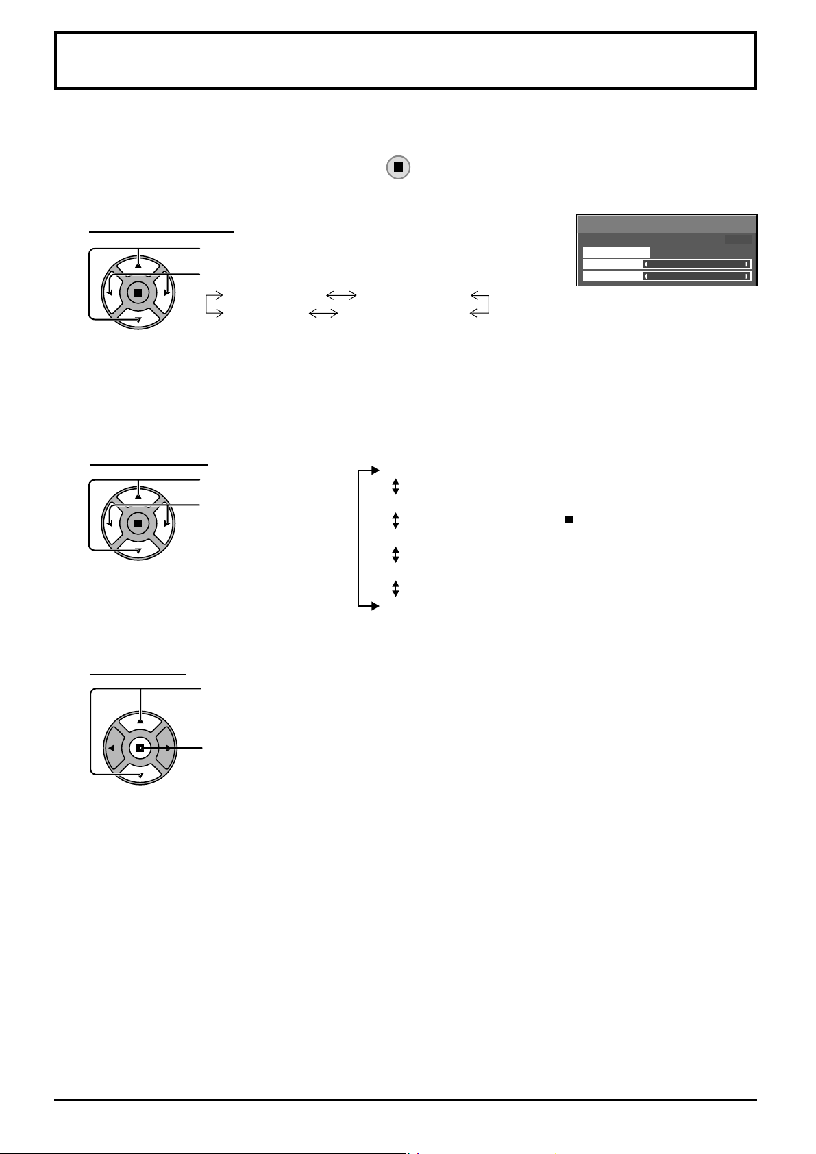
Screensaver (For preventing image retention)
Do not display a still picture, especially in 4:3 mode, for any length of time.
If the display must remain on, a Screensaver should be used.
Select “Screensaver” in “Setup” menu and press button.
1
Function selection
2
Mode selection
3
Screensaver
Press to select Function.
Press to select the desired function.
Negative image
White screen
Negative image : Negative image will be displayed on the screen.
Scrolling bar only
Overlay scrolling bar
White screen : The whole screen will be white.
Note: Overlay scrolling bar is not effective during two screen display.
Press to select Mode.
Press to select each
mode items.
Scrolling bar only
Overlay scrolling bar
: A white bar will scroll from left to right. The image won't be displayed.
: The brightness of the image will be decreased and a white bar will scroll
on it.
Standby after SCR Saver
On
Off
Interval
Time Designation : Operates when Start Time and Finish Time
: Operates while Screensaver duration, and
display enters standby mode.
: Operates when Start is selected and the
ACTION ( ) button is pressed.
: Operates when Periodic Time and Operating
Time are setup and those times arrive.
are setup and those times arrive.
Function
Mode
Start
Time 99:99
Scrolling bar only
Standby after SCR Saver
Start setting
4
When the Mode is set to On, press to select Start.
Press to start Screensaver.
The menu screen will disappear and the Screensaver will be activated. To stop the
Screensaver under On, press the R button or any buttons on the main unit.
Note: When the display is turned off, the Scrensaver will be deactivated.
37
Page 38
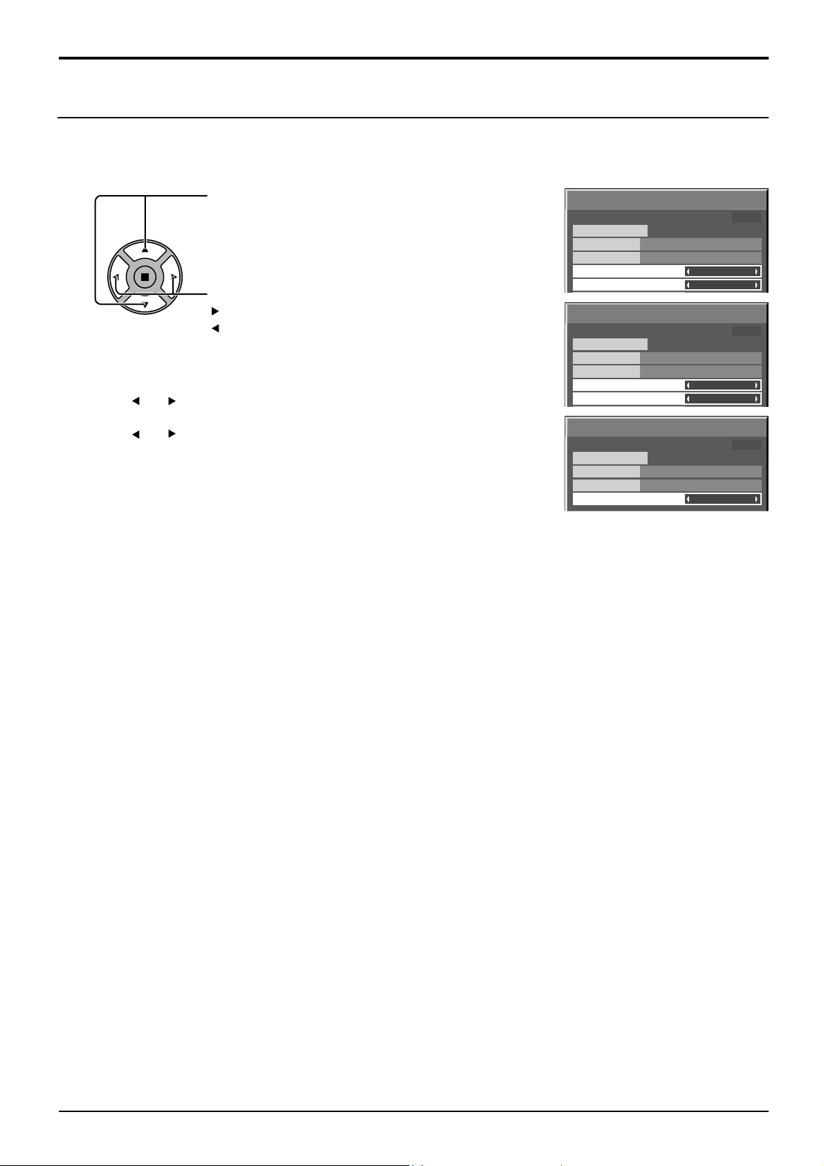
Screensaver (For preventing image retention)
Setup of Screensaver Time
After selecting Time Designation, Interval or Standby after SCR Saver, the relevant Time Setup will become available
for selection and the Operating Time may be set. (Time cannot be set when “Mode” is “On” or “Off”.)
Press to select Start Time / Finish Time
(when Time Designation is selected).
Press to select Periodic Time / Operating Time
(when Interval is selected).
Press to select Screensaver duration
(when Standby after SCR Saver is selected).
Press to setup.
button: Forward
button: Back
Notes:
• Pressing “ ” or “ ” button once changes the Time 1 minute.
[However, switching occurs every 15 minutes when Periodic Time is selected.]
• Pressing “ ” or “ ” button continuously changes the Time by 15 minutes.
• “Screensaver duration” of the “Standby after SCR Saver” can be set from 0:00
to 23:59. When this is set to “0:00”, “ Standby after SCR Saver” will not be
activated.
Note: Timer function will not work unless “Time” is set.
Screensaver
Start
Function
Mode
Start Time
Finish Time
Screensaver
Start
Function
Mode
Periodic Time
Operating Time
Screensaver
Start
Function
Mode
Screensaver duration
Standby after SCR Saver
Time 15:00
Scrolling bar only
Time Designation
6:15
12:30
Time 15:00
Scrolling bar only
Interval
12:00
3:00
Time 15:00
Scrolling bar only
6:15
38
Page 39
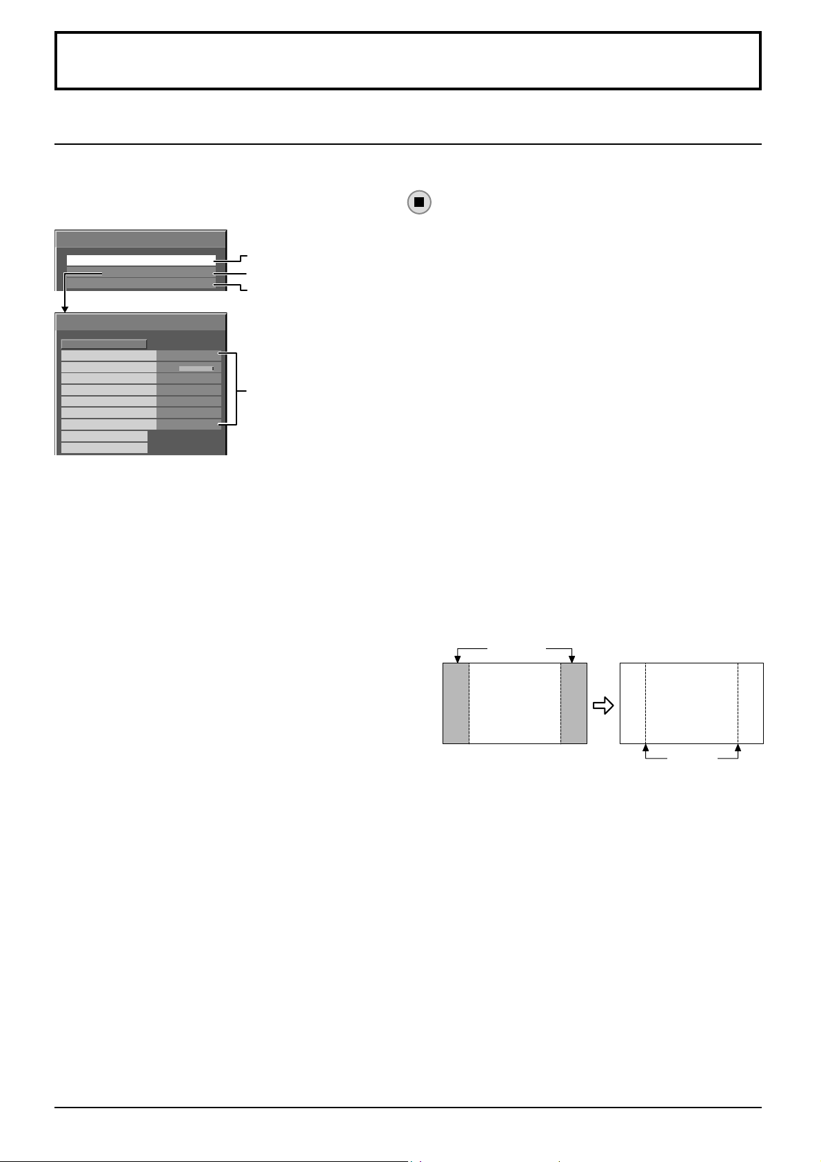
Reduces screen image retention
Extended life settings
The following settings are setup to reduce image retention:
Select “Extended life settings” in “Setup” menu and press button.
Extended life settings
Express settings
Custom settings
Reset
Extended life settings
Recommended settings
Picture Mode
Contrast
Side panel
NANODRIFT Saver
NANODRIFT Mode
Peak limit
Lock settings
Apply to current input
Apply to all inputs
Dynamic
30
High
High mid
Smooth
Off
unlock
Set to the recommended value
Set individually
Reset to the factory settings
Image Retention Reduction
Menu
Image Retention Reduction Menu
“Extended life settings” enables you to set the following 5 menus (Image Retention Reduction Menu) as recommended
values or set them individually.
Picture Mode
Contrast
“Picture Mode” and “Contrast” are same as “Picture” menu items (see page 26). The settings of this menu will be
refl ected to the “Picture” menu.
Side panel
Do not display a picture in 4:3 mode for an extended period,
as this can cause an image retention to remain on the side
panels on either side of the display fi eld.
To reduce the risk of such an image retention, illuminate
the side panels.
This function may be applicable to the non-picture area.
Off: Darken both ends.
Low: Make it dark gray.
Mid: Make it gray.
High: Make it light gray.
Notes:
• To reduce the occurrence of image retention, set the Side panel to High.
• The side panel may fl ash (alternate black/white) depending on the picture being shown on the screen. Using Cinema
mode will reduce such fl ashing.
side panel
4:3 Screen
Display
image
retention
39
Page 40
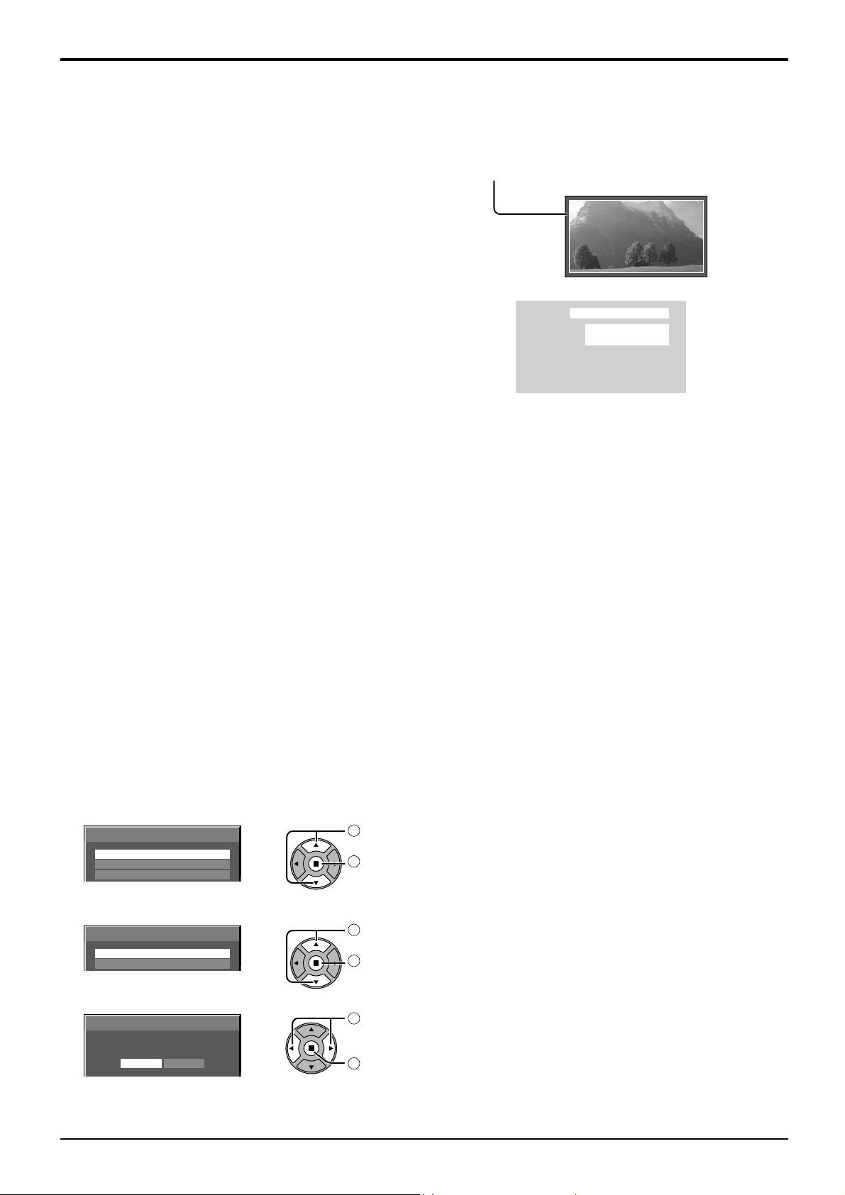
Reduces screen image retention
NANODRIFT Saver
Moves the display position of the screen slightly to reduce image retention on the display panel.
Min–Max: NANODRIFT Saver operates. The display position of the screen moves at set time intervals. You can set
the screen movement range. Some of the screen may appear to be missing as a result of this operation.
If you change the value, a mask is displayed in the range where the picture is missing as a result of
position movement.
When “NANODRIFT” Image Retention Reduction is
operating, “NANODRIFT” is displayed.
PC
16:9
NANODRIFT
Note:
This function does not work in the following cases.
When in digital zoom mode
NANODRIFT Mode
Sets the operation mode of NANODRIFT Saver.
Smooth: Moves by 1/16 dot
Pixel: Moves by 1 dot
Peak limit
On: Suppresses image contrast (peak brightness).
Note: When a still picture is viewed for an extended time, the screen may become slightly darker. (see page 58)
Express settings
Set the “Image Retention Reduction” menu to the recommended settings.
All menus will be locked.
Picture Mode: Normal
Contrast: Recommended setting for each model
Side panel: High
NANODRIFT Saver: High mid
NANODRIFT Mode: Smooth (“Pixel” when Touch Pen or Touch Panel mode)
Peak limit: On
Select “Express settings”.
1
Extended life settings
Express settings
Custom settings
Reset
Select the input to apply the settings.
2
Extended life settings
Apply to current input
Apply to all inputs
Select “Yes”.
3
Extended life settings
Apply to current input
NoYe s
40
select
1
access
2
select
1
set
2
select
1
set
2
Page 41
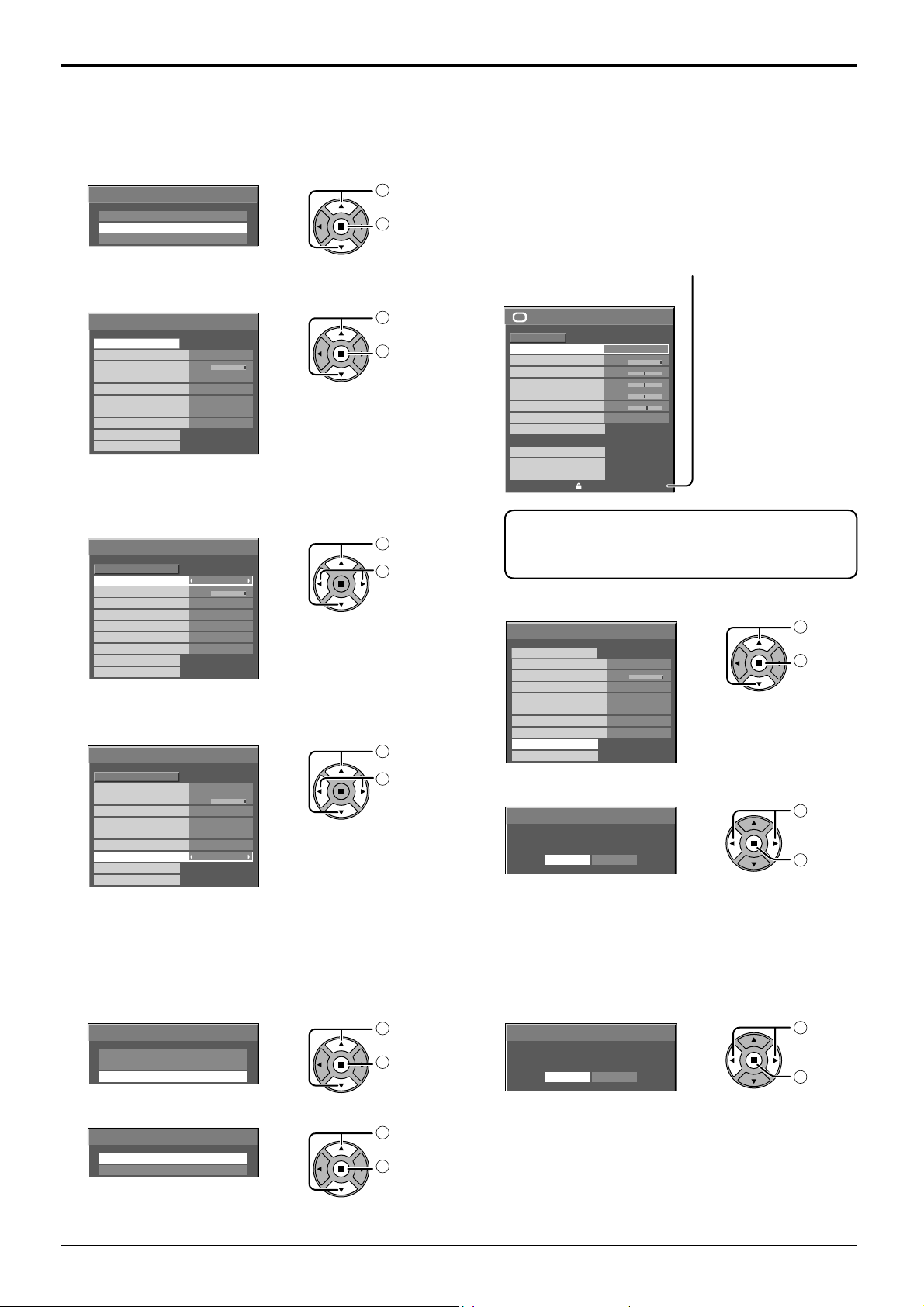
Custom settings
Set the individual “Image Retention Reduction” menu.
Reduces screen image retention
Select “Custom settings”.
1
Extended life settings
Express settings
Custom settings
Reset
To set each menu to the recommended setting:
2
Select “Recommended settings”.
Extended life settings
Recommended settings
Picture Mode
Contrast
Side panel
NANODRIFT Saver
NANODRIFT Mode
Peak limit
Lock settings
Apply to current input
Apply to all inputs
Dynamic
30
High mid
Smooth
Unlock
High
Off
Each menu will be set as same
as the “Express settings”.
Set each menu.
3
Extended life settings
Recommended settings
Picture Mode
Contrast
Side panel
NANODRIFT Saver
NANODRIFT Mode
Peak limit
Lock settings
Apply to current input
Apply to all inputs
To lock each menu setting:
4
Set the “Lock settings” to “Lock”.
Extended life settings
Recommended settings
Picture Mode
Contrast
Side panel
NANODRIFT Saver
NANODRIFT Mode
Peak limit
Lock settings
Apply to current input
Apply to all inputs
Dynamic
30
High mid
Smooth
Unlock
Dynamic
30
High mid
Smooth
High
Off
High
Off
Lock
select
1
access
2
select
1
set
2
select
1
adjust
2
select
1
adjust
2
When a menu is locked, it is grayed out and cannot
be set.
“Picture Mode” and “Contrast” will no longer be able
to set in the “Picture” menu, and they are labeled
with icon to indicate their locked status. Also,
“Normalise”, “Memory save” and “Memory load”
are not available.
Picture
Normal
Normalise
Picture Mode
Contrast
Brightness
Colour
Hue
Sharpness
White balance
Advanced settings
Memory save
Memory load
Memory edit
Dynamic
30
0
0
0
5
Normal
Extended life settings
Touch Pen mode when a menu is locked
When a menu is locked, “Touch-Pen Settings”
are disabled and Touch Pen mode cannot be set.
Select the input to apply the settings.
5
Extended life settings
Recommended settings
Picture Mode
Contrast
Side panel
NANODRIFT Saver
NANODRIFT Mode
Peak limit
Lock settings
Apply to current input
Apply to all inputs
Select “Yes”.
6
Extended life settings
Apply to current input
30
NoYe s
Dynamic
High
High mid
Smooth
Off
Lock
select
1
set
2
select
1
set
2
Reset
Reset the “Image Retention Reduction” menu to the factory settings. Each menu will be unlocked.
Select “Reset”.
1
Extended life settings
Express settings
Custom settings
Reset
Select the input to reset the settings.
2
Extended life settings
Reset current input
Reset all inputs
select
1
access
2
select
1
set
2
Select “Yes”.
3
Extended life settings
Reset current input
NoYe s
select
1
set
2
41
Page 42
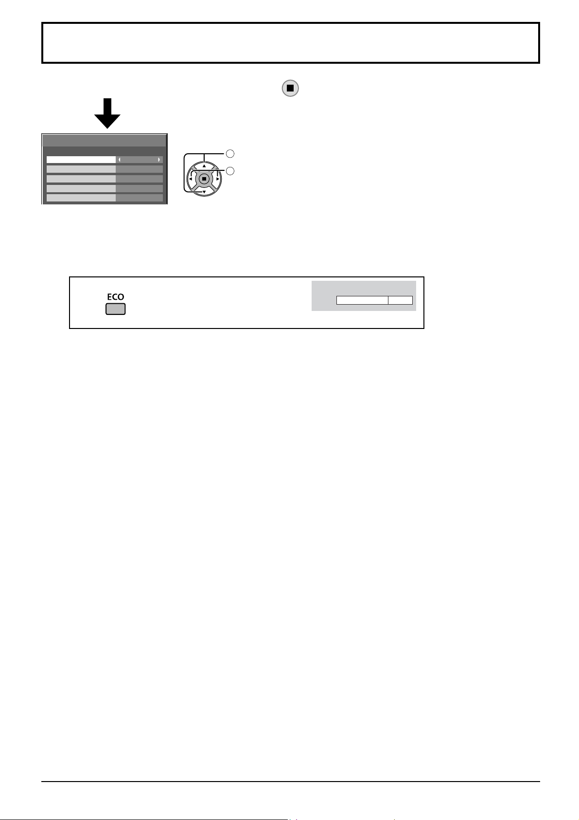
ECO Mode settings
Select “ECO Mode settings” in “Setup” menu and press button.
ECO Mode settings
select
ECO Mode
Power save
PC Power management
DVI-D Power management
No signal power off
Custom
Off
Off
Off
Disable
ECO Mode
Custom: The menu of power consumption reduction is individually set.
On: The following fi xed values are set to the menu of power consumption reduction. Individual setting is not available.
Power save: On DVI-D Power management: On
PC Power management: On No signal power off: Enable
Using Remote Control
When is pressed, the “ECO Mode” setting
changes.
1
adjust
2
ECO Mode On
Custom settings
The menu of the power consumption reduction is individually set. This setting is enabled when “ECO Mode” is set
to “Custom”.
Power save
When this function is turned On, luminous level of the Plasma Display is suppressed, so power consumption is
reduced.
Sensor:
Note:
PC Power management
When this function is set to On, it operates under the following conditions to turn the power on or off automatically.
When no pictures (HD/VD sync signals) are detected for 60 or so seconds during PC signal input:
→ Power is turned off (standby); the power indicator lights up orange.
When pictures (HD/VD sync signals) are subsequently detected:
→ Power is turned on; the power indicator lights up green.
Notes:
• This function operates only during PC signal input.
• This function is effective when “Sync” is set to “Auto”, “Component / RGB-in select” is set to “RGB” and during
normal viewing.
DVI-D Power management
When this function is set to On, it operates under the following conditions to turn the power on or off automatically.
When no pictures (sync signal) are detected for 60 or so seconds during DVI signal input:
→ Power is turned off (standby); the power indicator lights up orange.
When pictures (sync signal) are subsequently detected:
→ Power is turned on; the power indicator lights up green.
Notes:
• This function operates only during DVI signal input.
• This function is invalid during input from DVI-D Terminal Board (TY-FB11DD).
• Depending on the type of terminal board equipped, this function may be invalid.
The luminous level of the Plasma Display is automatically adjusted according to the viewing environment.
In Touch Pen mode, the sensor function is disabled.
No signal power off
Equipment power supply is turned Off when there is no signal.
When this is set to “Enable”, the power supply of the unit goes Off 10 minutes after the input signals stop.
42
Page 43
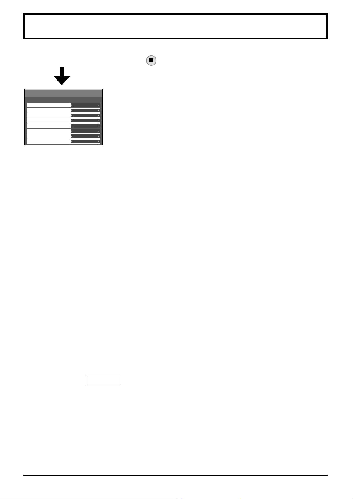
Customizing the Input labels
This function can change the label of the Input signal to be displayed. (see page 16)
Select “Input label” in “Setup” menu and press
Input label
button.
SLOT INPUT
VIDEO
COMPONENT
HDMI
DVI
PC
NETWORK
WHITEBOARD
SLOT INPUT
VIDEO
COMPONENT
HDMI
DVI
PC
NETWORK
WHITEBOARD
Image input Input label
[SLOT INPUT]*1 SLOT INPUT / DVD1 / DVD2 / DVD3 / DVD4 / Blu-ray1 / Blu-ray2 / Blu-ray3 / Blu-ray4 /
CATV / VCR / STB / (Skip)
[VIDEO] VIDEO / DVD1 / DVD2 / DVD3 / DVD4 / Blu-ray1 / Blu-ray2 / Blu-ray3 / Blu-ray4 / CATV /
VCR / STB / (Skip)
[COMPONENT]*2 COMPONENT / DVD1 / DVD2 / DVD3 / DVD4 / Blu-ray1 / Blu-ray2 / Blu-ray3 / Blu-ray4 /
CATV / VCR / STB / (Skip)
[HDMI] HDMI / DVD1 / DVD2 / DVD3 / DVD4 / Blu-ray1 / Blu-ray2 / Blu-ray3 / Blu-ray4 / CATV /
VCR / STB / (Skip)
[DVI] DVI / DVD1 / DVD2 / DVD3 / DVD4 / Blu-ray1 / Blu-ray2 / Blu-ray3 / Blu-ray4 / CATV /
VCR / STB / (Skip)
[PC] PC / DVD1 / DVD2 / DVD3 / DVD4 / Blu-ray1 / Blu-ray2 / Blu-ray3 / Blu-ray4 / CATV /
VCR / STB / (Skip)
[NETWORK] NETWORK / (Skip)
[WHITEBOARD] WHITEBOARD / (Skip)
(
Skip
): The INPUT button press will skip its input.
*1 “SLOT INPUT” is displayed when a Terminal Board is installed.
*2
“COMPONENT” may be displayed as “RGB” depending on the setting of “Component/RGB-in select”. (see page 46)
When a Terminal Board with dual input terminals is installed
“SLOT INPUT” is displayed as “SLOT INPUT A” and “SLOT INPUT B” and independent settings are available.
[SLOT INPUT A] SLOT INPUT A / DVD1 / DVD2 / DVD3 / DVD4 / Blu-ray1 / Blu-ray2 / Blu-ray3 / Blu-ray4 /
CATV / VCR / STB / (Skip)
[SLOT INPUT B] SLOT INPUT B / DVD1 / DVD2 / DVD3 / DVD4 / Blu-ray1 / Blu-ray2 / Blu-ray3 / Blu-ray4 /
CATV / VCR / STB / (Skip)
When a Terminal Board with fi xed display (such as Tuner Board) is installed
Skip
Only fi xed display and (
[SLOT INPUT] fi xed display / (
) are available as Input label of “SLOT INPUT”.
Skip
)
43
Page 44
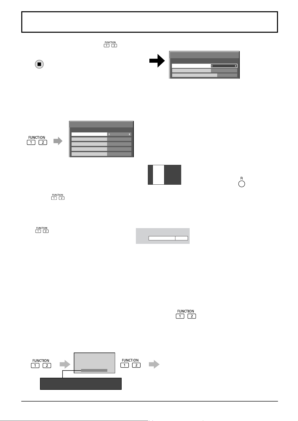
Function Button Settings
Set the functions that operates when is pressed.
Select “Function Button Settings” in “Setup” menu and
press button.
• Function Button 1, Function Button 2
The following functions are set to the FUNCTION button.
Note:
Factory settings are as follows.
Function Button Settings
Function Button 1
Function Button 2
Function Button Guide
Touch-Pen
Scrolling bar
On
FUNCTION1 button: Touch-Pen
FUNCTION2 button: Scrolling bar
ECO Mode settings / Signal / On/Off Timer Setup / MULTI PIP Settings
The menu is displayed. (Example: ECO Mode settings)
ECO Mode settings
ECO Mode
Power save
PC Power management
DVI-D Power management
No signal power off
Custom
Off
Off
Off
Disable
Pressing the FUNCTION button clears the menu.
Scrolling bar
Activates the “Scrolling bar only” screensaver.
After 15 minutes, the display enters standby mode.
To exit this mode, press button.
INPUT (SLOT)* - INPUT (WHITEBOARD)
Simply press to select the input.
* “INPUT (SLOT)” is displayed when an optional Terminal Board is installed.
When a Terminal Board with dual input terminals is installed, “INPUT (SLOT A)” and “INPUT (SLOT B)” are
displayed.
Touch-Pen
Press and turn Touch Pen mode On/Off.
Touch-Pen On
Network Setup
“Network Setup” menu is displayed.
Multi-Live
Switch to the Multi-Live mode when using the
“Wireless Manager”.
Computer Search
The list of connectable computers on the network is displayed.
Note:
For the network function, refer to “Operating Instructions, Network Operations” and the instruction manual of “Wireless
Manager” in use.
AV Mute
Mutes the audio and video. To exit this mode, press any
MULTI PIP
Press to turn MULTI PIP On/Off.
button.
• Function Button Guide
The function display setting for the FUNCTION button is confi gured.
On: Press the FUNCTION button to display the function list of the button.
Off: The function list is not displayed.
The operation starts.
Function
1:Touch-Pen 2:Scrolling bar
44
Page 45
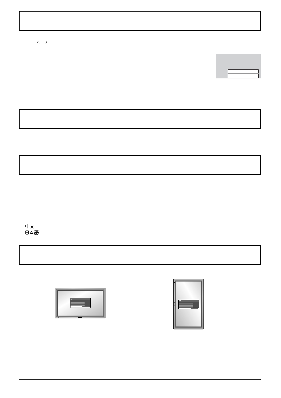
No activity power off
Disable Enable
When this function is set to “Enable”, the power is turned off (standby) automatically when there is no operation of
the Plasma Display for 4 hours.
Starting from 3 minutes before the turn off, the remaining time will be displayed.
Press any key to abort.
No activity power off
When the power is turned off due to this function, a message “Last turn off due to ’No activity power off’.” is
displayed next time the power is turned on.
Note:
During the screensaver is running, this function is disabled.
Menu Display Duration / OSD Brightness
Set the display time and brightness of the on-screen menu display.
Menu Display Duration: 5 S - 30 S
OSD Brightness: 1 - 5
OSD Language
Select your preferred language.
■
Selectable languages
English(UK)
Deutsch
Français
Italiano
Español
ENGLISH(US)
.......(Chinese)
.......(Japanese)
.......(Russian)Русский
3min
Display orientation
Sets the fan control, panel drive control, and the display style of on-screen menu for vertical installation.
Landscape Portrait
Fan control and panel drive control for
horizontal installation.
Notes:
• Turn up the power switch for the upward direction when you set Display vertically.
•
When you change this setting, fan control and panel drive control will be switched as the power is turned on next time.
Fan control and panel drive control for vertical
installation. On-screen menu will be rotated 90
degrees counterclockwise to be suitable for the
setting.
45
Page 46
Setup for Input Signals
Component / RGB-in select
Component RGB
Select to match the signals from the source connected to the Component / RGB or PC input terminals.
Y, PB, PR signals “Component”
RGB signals “RGB”
Note:
Make setting of the selected input terminal (COMPONENT/RGB IN or PC IN).
YUV / RGB-in select
YUV RGB
Select to match the signals from the source connected to the DVI input terminals.
YUV signals “YUV”
RGB signals “RGB”
Notes:
• Selection may not be possible, depending on which optional board is installed.
• Make setting of the selected input terminal (SLOT or DVI-D IN).
46
Page 47
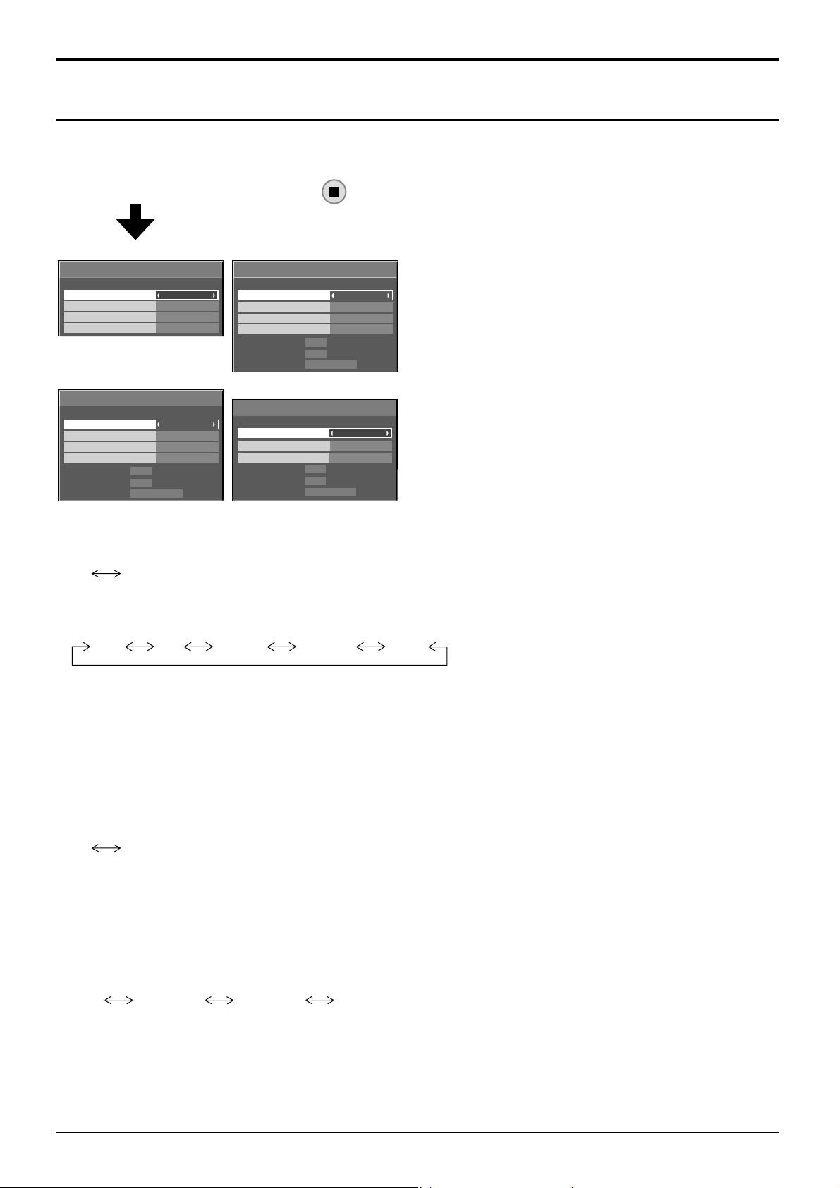
Setup for Input Signals
Signal menu
Notes:
• “Signal” setup menu displays a different setting condition for each input signal.
• Depending on the input signal type, an optional Terminal Board may be required.
Select “Signal” in “Setup” menu and press button.
For Video (S VIDEO) For RGB
Signal
3D Y/C Filter (NTSC)
Colour system
Cinema reality
Noise reduction
For Component
Signal
Sync
Cinema reality
XGA Mode
Noise reduction
H-Freq.
63.98
V-Freq.
Signal Format
60.02
1280×1024/60i
On
Auto
Off
Off
[
Component
Auto
Off
Auto
Off
kHz
Hz
[ AV ]
Signal
Sync
Cinema reality
XGA Mode
Noise reduction
H-Freq.
V-Freq.
Signal Format
For Digital
]
Signal
Cinema reality
HDMI Range
Noise reduction
H-Freq. kHz63.98
V-Freq. Hz
Signal Format 1280×1024/60i
63.98
60.02
1280×1024/60i
60.02
kHz
Hz
Auto
Off
Auto
Off
[
Off
Auto
Off
[
RGB
Digital
]
]
• 3D Y/C Filter (NTSC)
This menu is displayed when BNC Dual Video Terminal Board (TY-FB9BD) is installed to the unit.
Set this menu when the moving image looks unnatural during Video (S Video) input signal.
On Off
Note:
When On, this setting only affects NTSC input signals.
• Colour system
Auto SECAM M.NTSC NTSCPAL
Set the colour system to match the input signal. When “Auto” is set, Colour system will be automatically selected
from NTSC/PAL/SECAM/M.NTSC.
To display PAL60 signal, select “Auto” or “PAL”.
If the picture image becomes unstable:
With the system set on Auto, under conditions of low level or noisy input signals the image may in rare cases
become unstable. Should this occur, set the system to match the format of the input signal.
• Cinema reality
When “On”, the display attempts to reproduce a more natural interpretation of sources such as movie pictures,
which are recorded at 24 frames per second.
If the picture is not stable, turn the setting to “Off”.
On Off
Note:
When On, this setting only affects the following signal input:
• NTSC / PAL signal input during Video (S Video) input signal.
• 525i(480i), 625i(575i), 1125(1080)/60i signal input during “Component” input signal.
• XGA Mode
This menu is displayed when the input signal is analog (Component/PC). This unit supports three types of XGA
signals with 60Hz vertical frequency having different aspect ratios and sampling rates (1,024 × 768 @ 60Hz,
1,280 × 768 @ 60Hz and 1,366 × 768 @ 60Hz).
Auto 1024×768 1280×768 1366×768
Auto: Automatically selected from 1024×768/1280×768/1366×768.
Switch the setting to suit the input signal for better display depends on the angle of view or display
resolution condition.
Note:
After making this setting, be sure to make each adjustment (such as “Auto Setup”) on the “Pos./Size” menu as
necessary. (see page 23)
47
Page 48

Setup for Input Signals
• Sync
This function operates only during input from PC IN terminal.
Setting RGB sync signal
Confi rm that the input is set to RGB input (this setting is valid only for RGB input signal).
Auto:
on G:
Setting Component sync signal
Confi rm that the input is set to Component input (this setting is valid only for Component input signal).
Auto:
on Y: Uses a synchronized signal on the Video Y signal, which is input from the Y connector.
Note:
Signals input to COMPONENT/RGB IN terminals correspond to Sync on G or Sync on Y.
• SDI Through
Set the active through function of the Dual Link HD-SDI Terminal Board (TY-FB11DHD).
On Off
On: Enables active through.
Off: Disables active through.
Note:
Settings can only be performed for this menu when a slot mounted with a Dual Link HD-SDI Terminal Board
(TY-FB11DHD) is selected.
The H and V sync or synchronized signal is automatically selected. If both input, it is selected the H and V sync.
Uses a synchronized signal on the Video G signal, which is input from the G connector.
The H and V sync or synchronized signal is automatically selected. If both input, it is selected the H and V sync.
• HDMI Range
Switches the dynamic range according to the input signal from HDMI terminal.
Video(16-235) Full(0-255) Auto
Video(16-235): If the input signal is the video range, Example: HDMI terminal output for DVD player
Full(0-255): If the input signal is full range, Example: HDMI terminal output for personal computer
Auto:
Switches the dynamic range automatically between “Video(16-235)” and “Full(0-255)” according to the input signal.
Note:
This function can be set only for HDMI signal input.
48
Page 49
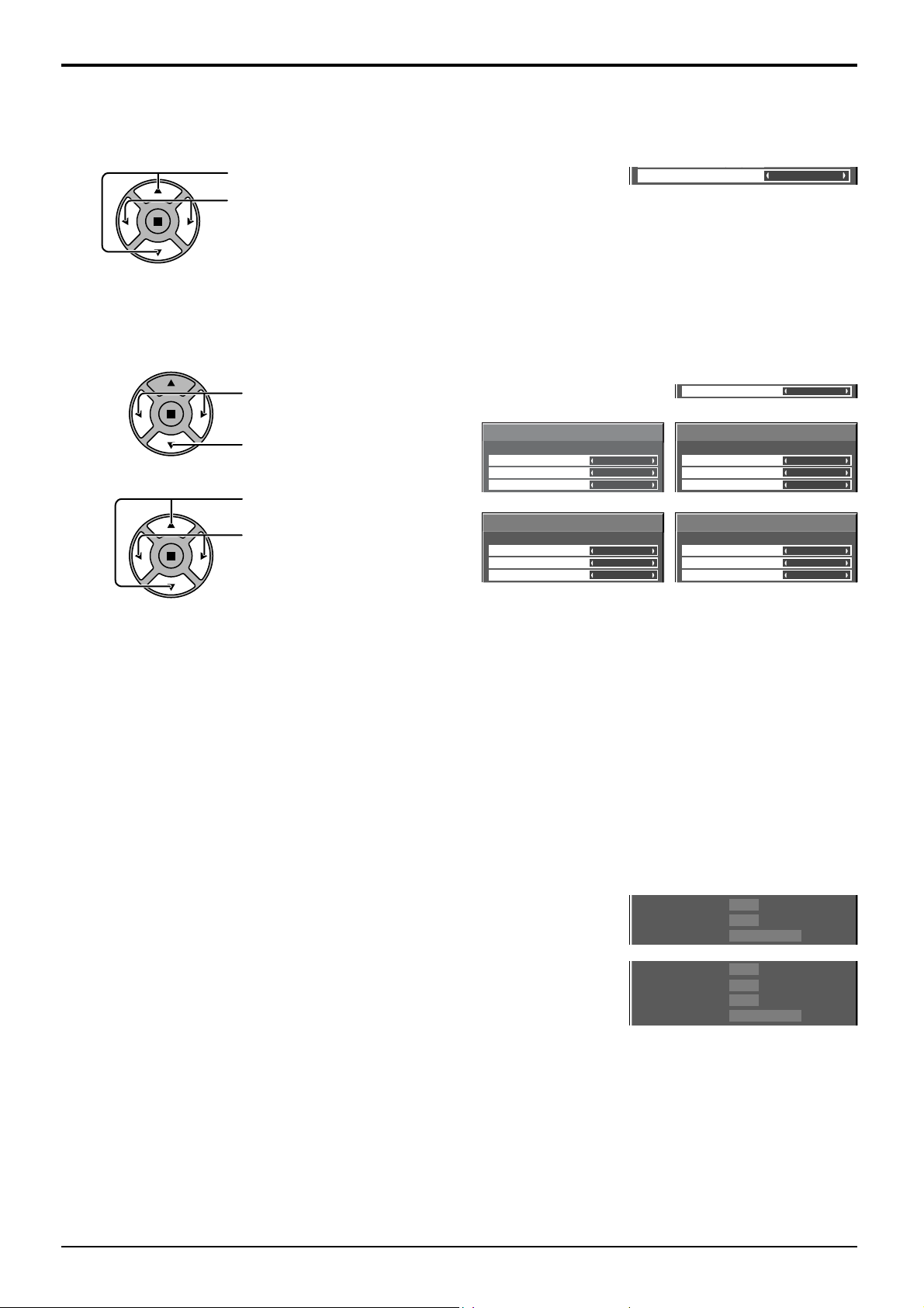
()
• Noise reduction
Sets the following three NR (Noise Reduction) functions together.
P-NR, Mosquito NR, Block NR
Setup for Input Signals
Press to select “Noise reduction”.
Press to select “Off”, “Min” , “Mid” , “Max” , “Advanced”.
Advanced NR
Sets the three NR functions separately.
1
2
Press to select “Advanced”.
Press to enter Advanced NR.
Press to select P-NR, Mosquito
NR or Block NR.
Press to select “Off”, “Min”, “Mid”,
“Max”.
Advanced NR
P-NR
Mosquito NR
Block NR
Advanced NR
P-NR
Mosquito NR
Block NR
[ AV ]
Off
Off
Off
[
Component
Off
Off
Off
Noise reduction
Noise reduction
Advanced NR
P-NR
Mosquito NR
Block NR
]
Advanced NR
P-NR
Mosquito NR
Block NR
Off
Advanced
[
RGB
Off
Off
Off
[
Digital
Off
Off
Off
▼
]
]
P-NR: Automatically reduces unwanted picture noise.
Mosquito NR
: Reduces mosquito noise around subtitles on MPEG videos.
Block NR: Reduces block noise when playing MPEG videos.
Note:
Noise reduction cannot be adjusted while a PC signal is being applied.
• Input signal display
Displays the frequency and the type of the current input signal.
This display is valid only for Component / RGB / PC and Digital input signal.
Display range:
Horizontal 15 - 110 kHz
Vertical 48 - 120 Hz
The dot clock frequency is displayed during DVI signal input.
H-Freq.
V-Freq.
Signal Format
H-Freq.
V-Freq. Hz
Dot Clock Freq.
Signal Format 1280×1024/60i
kHz
63.98
Hz
60.02
1280×1024/60i
kHz
63.98
60.02
MHz
108.0
49
Page 50
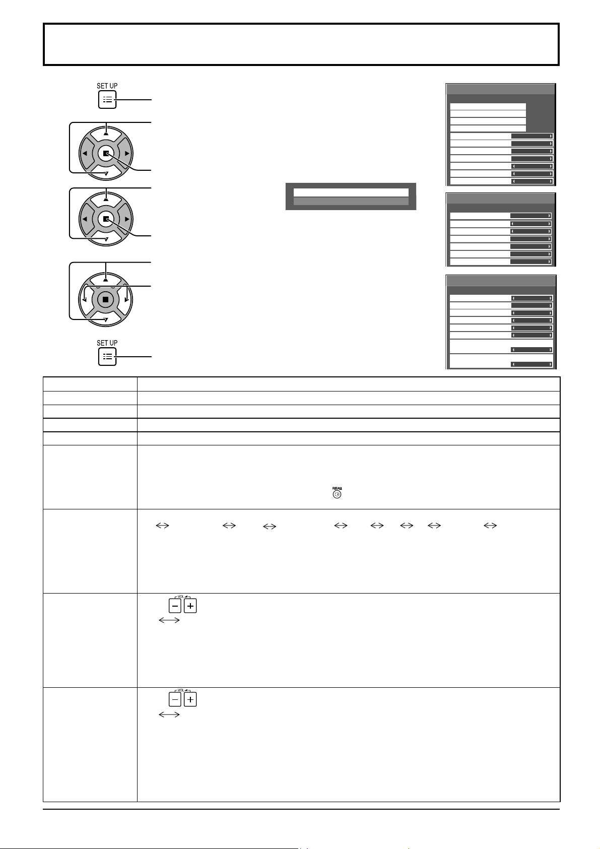
Options Adjustments
1
2
3
4
5
Press to display the Setup menu.
Press to select “OSD Language”.
Press for more than 3 seconds.
Press to select “Options”.
Press to display the Options menu.
Press to select your preferred menu.
Press to adjust the menu.
Press to exit from Options menu.
Options
Shipping
Options
Weekly Command Timer
Audio input select
Touch Panel settings
Input Search
Onscreen display
Initial input
Initial VOL level
Maximum VOL level
Input lock
Button lock
Remocon User level
Options
Off-timer function
Initial Power Mode
ID select
Serial ID
Display size
Studio W/B
Studio Gain
Options
Slot power
Power On Screen Delay
Clock Display
All Aspect
Auto Setup
Rotate
Power On Message (No activity power off)
Power On Message (Power Management)
On
Off
Off00
Off
Off
Off
Off
Enable
Normal
0
Off
Off
Off
Off
O f f
Off
Off
Off
Manual
Off
On
On
1/3
2/3
3/3
Item Adjustments
Weekly Command Timer
Audio input select
Touch Panel settings
Input Search
Onscreen display
Initial input
Initial VOL level
Sets Weekly Command Timer. (see page 53)
Set up the sound when an image input is selected. (see page 55)
Set while using Touch Panel (available as an option). (see page 56)
Set auto input switching for when there is no signal. (see page 57)
On: Displays all the following on screen.
• Power on display
• Input signal switch display
• No signal display
• Mute and the remaining time of off-timer after
was pressed.
Off: Hides all the items above from view.
Adjusts the input signal when the unit is turned on.
Off SLOT INPUT*1 VIDEO COMPONENT*2 HDMI DVI PC NETWORK WHITEBOARD
*1 “SLOT INPUT” is displayed when an optional Terminal Board is installed.
When a Terminal Board with dual input terminals is installed, “SLOT INPUT A” and “SLOT INPUT B” are displayed.
*2
“COMPONENT” may be displayed as “RGB” depending on the setting of “Component/RGB-in select”. (see page 46)
Notes:
• Only the adjusted signal is displayed. (see page 16)
• This menu is available only when “Input lock” is “Off”.
Press
Off
button to adjust the volume when the unit is turned on.
On
Off: Sets normal volume.
On: Sets your preferred volume.
Notes:
•
When “Maximum VOL level” is “On”, the volume can only be adjusted between 0 and your maximum range.
• You can hear the changed volume regardless of your volume setting before opening the options menu
if you adjust the volume when “Initial VOL level” is “On” and cursor is on the menu.
Maximum VOL level
50
Press
Off
button to adjust the maximum volume.
On
Off: Sets auto maximum volume.
On: Sets your preferred maximum volume.
Notes:
• If the “Maximum VOL level” is set lower than the “Initial VOL level”, the “Initial VOL level” automatically
becomes the same as the “Maximum VOL level”.
• The volume display can go up to 63 regardless of the settings.
• You can hear the changed volume regardless of your volume setting before opening the options menu
if you adjust the volume when “Maximum VOL level” is “On” and cursor is on the menu.
Page 51
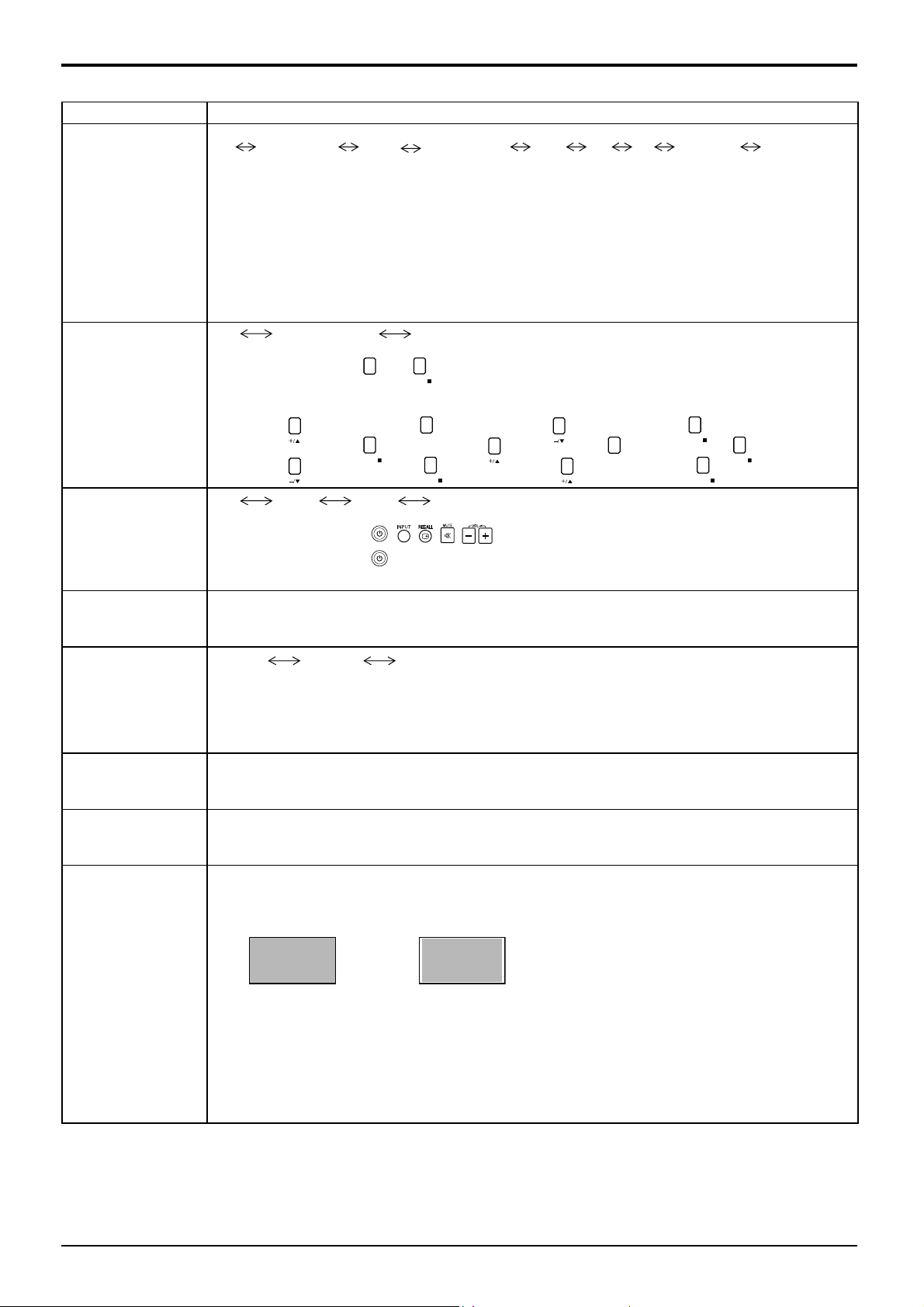
Item Adjustments
Input lock
Button lock
Remocon User level
Off-timer function
Options Adjustments
Locks the input switch operation.
Off SLOT INPUT*1 VIDEO COMPONENT*2 HDMI DVI PC NETWORK WHITEBOARD
*1 “SLOT INPUT” is displayed when an optional Terminal Board is installed.
When a Terminal Board with dual input terminals is installed, “SLOT INPUT A” and “SLOT INPUT B”
are displayed.
*2 “COMPONENT” may be displayed as “RGB” depending on the setting of “Component/RGB-in select”.
(see page 46)
Notes:
• Only the adjusted signal is displayed (see page 16).
• Input switch can be used when this is set to “Off”. Two screen display cannot be selected.
• In two screen display mode, if anything other than “Off” is set, the value will be fi xed as the value input
in the single screen display mode.
Off MENU&ENTER On
Off: All the buttons on main unit can be used.
MENU&ENTER: Locks
On: Locks all the button on main unit.
Sets Button lock with the unit buttons in the following procedure.
Off: Press
MENU&ENTER:
four times→Press
Press
On: Press four times→Press
Off
User1 User2 User3
Off: You can use all of the buttons on the remote control.
User1: You can only use
User2: You can only use
Locks all the buttons on remote control.
User3:
Enable: Enables the “Off-timer function”.
Disable: Disables the “Off-timer function”.
Note: When “Disable” is set, the Off-timer is cancelled.
ENTER/
MENU
and
buttons on main unit.
ENTER/
four times→Press four times→Press
INPUT
four times→Press
four times→Press four times→Press
ENTER/
four times→Press
, , , , buttons on the remote control.
button on the remote control.
four times→Press
INPUT
ENTER/
ENTER/
ENTER/
Initial Power Mode
ID select
Serial ID
Display size
Normal
Standby On
Sets the power mode of the unit for when the power recovers from failure or after plugging off and in again.
Normal: Power returns in as the same state as before the power interruption.
Standby
: Power returns in standby mode. (Power Indicator : red/orange)
On: Power returns in power On. (Power Indicator : green)
Note: When using multiple displays, “Standby” is preferred to be set in order to reduce a power load.
Sets panel ID number when panel is used in “Serial ID”.
Set value range: 0 - 100
(Standard value: 0)
Sets the panel ID Control.
Off: Disables external control by the ID.
On: Enables the external control by the ID.
Adjusts the image display size on screen.
Off: Sets the normal image display size on screen.
On: Sets the image display size approximately 95 % of the normal image display.
Off On
Notes:
• This setting is valid only when the input signals are as follows;
NTSC, PAL, SECAM, M.NTSC, PAL60, PAL-M, PAL-N (Video)
525i, 525p, 625i, 625p, 750/60p, 750/50p, 1125/60i, 1125/50i, 1125/24sF, 1125/25p, 1125/24p,
1125/30p, 1125/60p, 1125/50p, 1250/50i (Component Video, RGB, DVI, SDI, HDMI)
• This setting is invalid when digital zoom is selected.
• When “Display size” is set to “On”, “H-Pos” and “V-Pos” in “Pos./Size” can be adjusted.
• Refer to each board’s operating instruction for DVI, SDI, HDMI’s corresponding signals.
51
Page 52
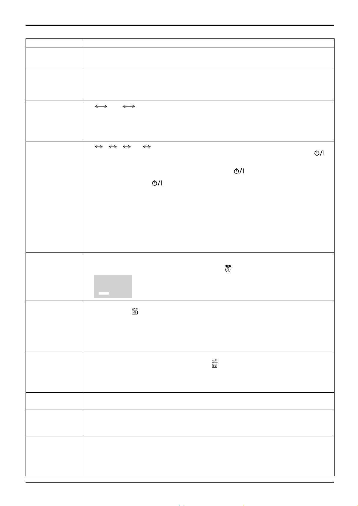
Options Adjustments
Item Adjustments
Off: Nullify all the settings adjusted.
Studio W/B
Studio Gain
On: Sets the colour temperature for TV studio.
Note: Valid only when the “Warm” is set as “White balance” in Picture menu.
Sharpens the contrast for a better view when a part of the image is too light to see.
Off: Disables “Studio Gain”.
On: Enables “Studio Gain”.
Note: This setting is valid only when the input signals are as follows:
Component Video, RGB (analog), SDI, HDMI
Slot power
Power On Screen
Delay
Clock Display
All Aspect
Auto Setup
Rotate
Power On Message
(No activity power
off)
Power On Message
(Power Management)
Off
Off: Power is not transmitted to the slot power.
Auto: Power is transmitted to the slot power only when main power is on.
On: Power is transmitted to the slot power when main power is on or in the standby state.
Note: In some cases, power is transmitted to the slot power when main power is on or in the standby
Off
You can set the power-on delay time of the displays to reduce the power load, when you press
turn on the multiple displays that are set together.
Set each display’s setting individually.
Off: The display will be turned on at the same time as
1 to 30 (sec.)
After pressing
Notes:
• During this function is working, the power indicator is blinking green.
• This function also works when the power recovers from failure or after plugging off and in again the
power cord.
After you unplug and plug the power cord in while the unit is in standby mode and also the power is
being supplied to a terminal board, the unit will start supplying the power to the board with time delay
according to the setting.
The power indicator lights up red fi rst and it turns orange when the power starts being supplied to the
board.
Off: Not display the clock.
On: Display the clock.
The clock is displayed at the lower left of the screen when
Note: When “Day/Time Setup” is not set, the clock is not displayed even if “Clock
Sets All Aspect mode (advanced aspect setting) or default aspect mode.
With each press of
Off: Default aspect mode
On: All Aspect mode
Aspect mode of each setting is as follows:
(Example: HD signal)
Off 4:3→4:3 Full→Zoom1→Zoom2→Zoom3→16:9→14:9→Just
On 4:3 (1)→4:3 (2)→4:3 Full→Zoom1→Zoom2→Zoom3→16:9→14:9→Just1→Just2
Sets the operational mode of the automatic position adjustment in the Pos./Size menu.
Manual: Automatic position adjustment starts when
Auto: Other than remote control or menu operation, automatic position adjustment starts:
When the display power is turned ON.
When the input signal is switched.
Off: Does not rotate the image.
On: Rotates the image 180 degrees.
Whether to show/hide No activity power off Precautions at the time of power ON is set.
On: The warning precautions are shown at the time of power ON.
Off: The warning precautions are not shown at the time of power ON.
Note: This setting is enabled only if “No activity power off” is “Enable” (see page 45).
Whether to show/hide an information message that tells the power has been turned off by Power
Management when the power is set to ON.
On: The information is shown at the time of power ON.
Off: The information is not shown at the time of power ON.
Note: This setting is enabled only if “PC Power management” or “DVI-D Power management” is “On”
Auto On
state regardless of the slot power setting.
1 2 3.... 30
to
is pressed.
: Set the power-on delay time (second).
, the display will be powered on with time delay depending on this
setting.
button is pressed.
Display” is “On”. (see page 33)
10:00
button, the aspect changes in the selected mode.
is pressed on the remote control or automatic
position adjustment is executed from the Pos./Size menu.
(see page 42).
52
Page 53
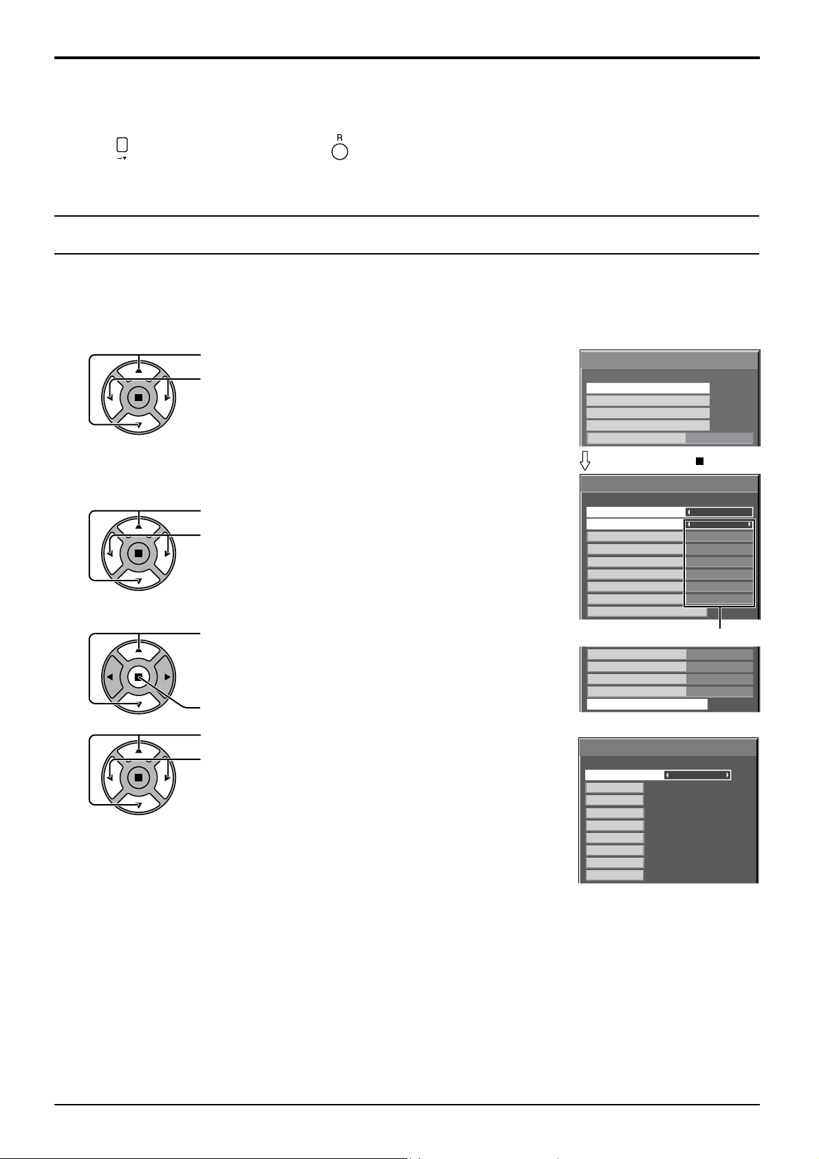
y
Options Adjustments
Normalisation
When both main unit buttons and remote control are disabled due to the “Button lock” or “Remocon User level”
adjustments, set all the values “Off” so that all the buttons are enabled again.
Press the
button on main unit together with button on the remote control and hold for more than 5 seconds. The
“Shipping” menu is displayed and the lock is released when it disappears.
Weekly Command Timer
You can set 7-day timer programming by setting time and command.
Note:
Before setting Weekly Command Timer, set Day/Time Setup. (see page 33)
1
2
3
4
Press to select Function.
Press to select “On”.
Note:
• When Function is set to On, On/Off Timer
Setup (see page 33) is unavailable and
Interval / Time Designation in Mode of
Screensaver (see page 37) cannot be
selected.
Press to select a day.
Press to select a program number.
Note:
• You can set the program from 1 to 7.
--- indicates unset.
Press to select Program Edit.
Press to show the Program Edit screen.
Press to select Program.
Press to change the program numbers (1-7).
Options
Weekly Command Timer
Audio input select
Touch Panel settings
Input Search
Onscreen display
Press ACTION ( ) button
Weekly Command Timer
Function
Monday
Tuesday
Wednesday
Thursday
Friday
Saturday
Sunday
Program Edit
Program number
Thursday
Friday
Saturday
Sunday
Program Edit
Program Edit screen
Weekly Command Timer
--:--
--:--
--:--
--:--
1
PON
IMS:SL1
---
---
---
DAM:ZOOM
AVL :10
---
Program
01
02
03
04
05
06
07
08
8:00
10:30
12:00
9:12
1/3
On
On
Program1
Program3
---
Program3
---
Program6
Program4
Program3
---
Program6
Program4
1/8
53
Page 54
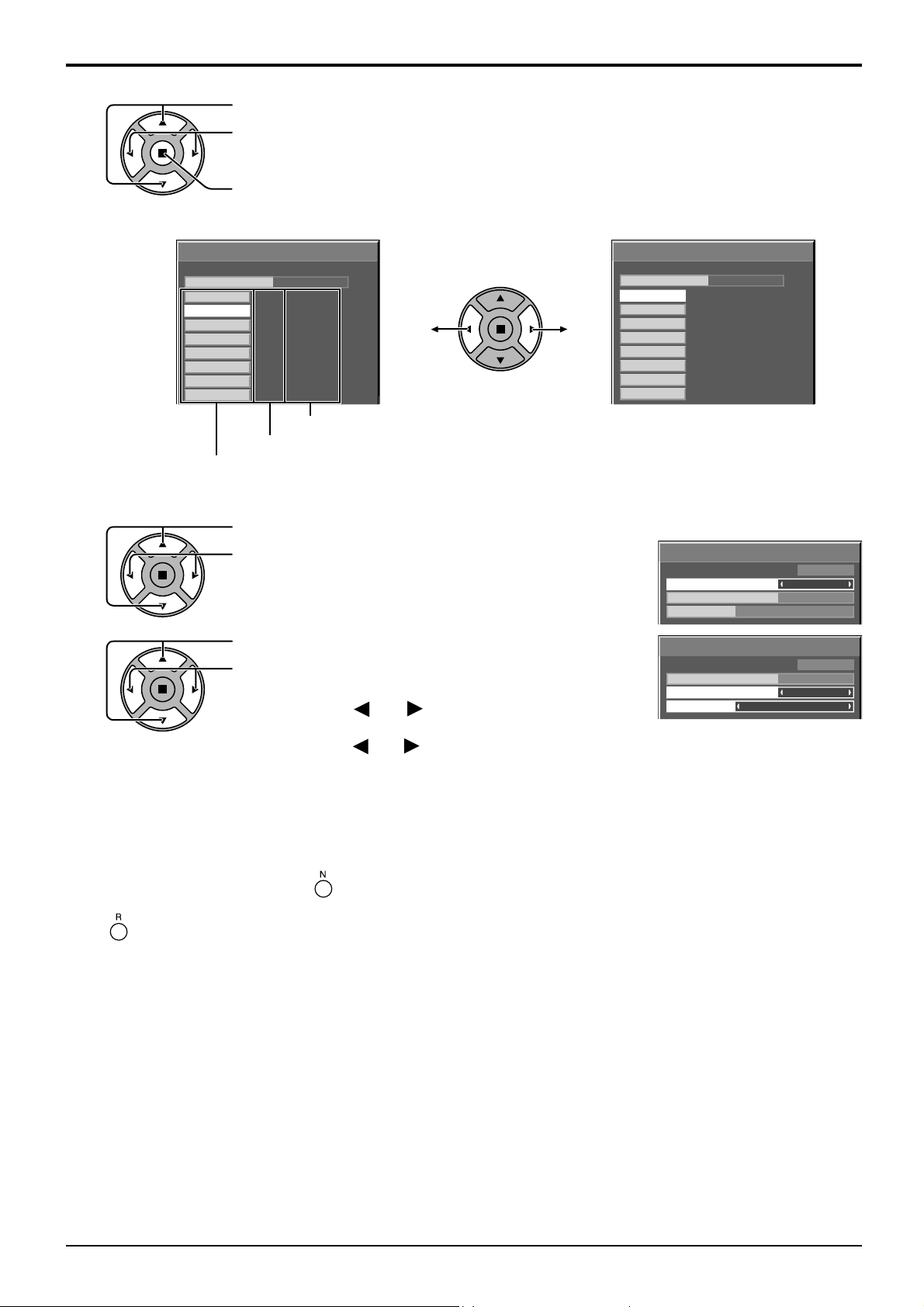
Options Adjustments
5
6
Press to select a command number.
Press to show the previous / next command
pages (1-8) of the selected program.
Press to show the command setting screen.
Weekly Command Timer
Program
01
02
03
04
05
06
07
08
8:00
10:30
--:--
--:--
--:--
12:00
9:12
--:--
PON
IMS:SL1
---
---
---
DAM:ZOOM
AVL:10
---
Command (--- indicates unset)
Set time of timer(--:-- indicates unset)
Command numbers
Press to select Command No.
Press to select a command number.
1/8
1
Weekly Command Timer
Program
57
58
59
60
62
63
64
61
20:00
20:30
22:00
--:--
--:--
--:--
--:--
--:--
1
AVL:00
DAM:NORM
POF
---
---
---
---
---
8/8
Command setting screen
Weekly Command Timer
Command No
Time
Command
Program
IMS:SL1
02
10:30
1
7
Press to select Time / Command.
Press to set each item.
Time: Set the time to execute a command program.
Pressing “ ” or “ ” button once changes “Time” 1
minute.
Pressing “ ” or “ ” button continuously changes “Time” by 15 minutes.
Command: Select a command to execute at the set time. This unit has 64 commands to set.
(see page 62)
Notes:
•
Command is performed in order of execution time, regardless of the command number.
• If a command execution time overlaps with that of other commands, these commands are
performed in number order.
• Pressing , Time becomes --:-- and Command becomes ---.
Note:
Press to return to the previous screen.
Weekly Command Timer
Program
Command No
Time
Command
1
02
10:30
IMS:SL1
54
Page 55
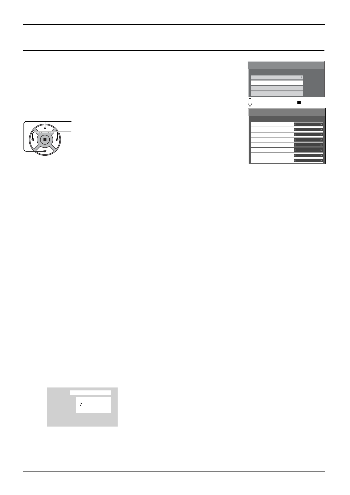
Audio input select
Options Adjustments
Set up the sound when an image input is selected.
Options
Weekly Command Timer
Audio input select
Touch Panel settings
Input Search
1/3
Press ACTION ( ) button
Audio input select
Press to select image input.
Press to select audio input.
SLOT INPUT
VIDEO
COMPONENT
HDMI
DVI
PC
NETWORK
WHITEBOARD
♪ SLOT INPUT
♪
AUDIO 1
♪
AUDIO 1
♪ HDMI
♪ AUDIO 2
♪ AUDIO 2
♪ NETWORK
NO AUDIO
Image input Audio input
[SLOT INPUT]*1 SLOT INPUT / AUDIO 1 / AUDIO 2 / NETWORK / NO AUDIO
[VIDEO] SLOT INPUT / AUDIO 1 / AUDIO 2 / NETWORK / NO AUDIO
[COMPONENT]*2 SLOT INPUT / AUDIO 1 / AUDIO 2 / NETWORK / NO AUDIO
[HDMI] SLOT INPUT / AUDIO 1 / HDMI / AUDIO 2 / NETWORK / NO AUDIO
[DVI] SLOT INPUT / AUDIO 1 / AUDIO 2 / NETWORK / NO AUDIO
[PC] SLOT INPUT / AUDIO 1 / AUDIO 2 / NETWORK / NO AUDIO
[NETWORK] SLOT INPUT /AUDIO 1 / AUDIO 2 / NETWORK / NO AUDIO
[WHITEBOARD] SLOT INPUT / AUDIO 1 / AUDIO 2 / NETWORK / NO AUDIO
NO AUDIO: No audio input (Mute)
*1 “SLOT INPUT” is displayed when a Terminal Board is installed.
*2 “COMPONENT” may be displayed as “RGB” depending on the setting of “Component/RGB-in select”.
(see page 46)
When a Terminal Board with dual input terminals is installed
“SLOT INPUT” is displayed as “SLOT INPUT A” and “SLOT INPUT B” and independent settings are available.
To set other image inputs, you can select “SLOT INPUT A” and “SLOT INPUT B”.
Image input Audio input
[SLOT INPUT A] SLOT INPUT A / AUDIO 1 / AUDIO 2 / NETWORK / NO AUDIO
[SLOT INPUT B] SLOT INPUT B / AUDIO 1 / AUDIO 2 / NETWORK / NO AUDIO
[VIDEO] SLOT INPUT A / SLOT INPUT B / AUDIO 1 / AUDIO 2 / NETWORK / NO AUDIO
[COMPONENT] SLOT INPUT A / SLOT INPUT B / AUDIO 1 / AUDIO 2 / NETWORK / NO AUDIO
[HDMI]
SLOT INPUT A / SLOT INPUT B /
AUDIO 1 / HDMI / AUDIO 2
/ NETWORK / NO AUDIO
[DVI] SLOT INPUT A / SLOT INPUT B / AUDIO 1 / AUDIO 2 / NETWORK / NO AUDIO
[PC] SLOT INPUT A / SLOT INPUT B / AUDIO 1 / AUDIO 2 / NETWORK / NO AUDIO
[NETWORK] SLOT INPUT A / SLOT INPUT B / AUDIO 1 / AUDIO 2 / NETWORK / NO AUDIO
[WHITEBOARD] SLOT INPUT A / SLOT INPUT B / AUDIO 1 / AUDIO 2 / NETWORK / NO AUDIO
When Image input and Audio input differ from each other, the Audio input is displayed as below.
PC
COMPONENT
16:9
NANODRIFT
Notes:
• HDMI Audio is selectable only for HDMI Input.
• You cannot set audio of B for SLOT INPUT A, or audio of A for SLOT INPUT B.
55
Page 56
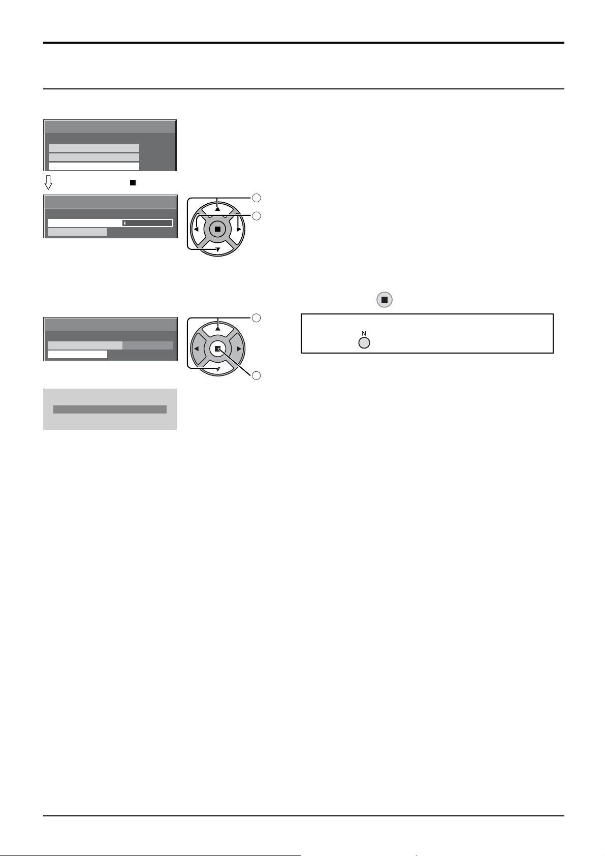
Options Adjustments
Touch Panel settings (Settings when using Touch Panel)
The mode to restrict NANODRIFT Saver (see page 40) operation when using Touch Panel (available as an option) is set up.
Options
Weekly Command Timer
Audio input select
Touch Panel settings
Press ACTION ( ) button
Touch Panel settings
Touch Panel mode
Calibration mode
On
1/3
Set “Touch Panel mode” to “On”.
select
1
adjust
2
Calibration mode
This setting is used in calibrating a touch panel.
You can confi gure the setting if “Touch Panel mode” is “On”.
Select “Calibration mode” and then press .
select
Touch Panel settings
Touch Panel mode
Calibration mode
ª
On
1
2
set
The screen is displayed in the middle and NANODRIFT is deactivated for 180
Calibration mode
seconds.
After 180 seconds or when you have the menu displayed with a remote control,
Calibration mode is cancelled.
When the menu is not displayed (normal screen)
Hold down for over 3 seconds.
Note:
For information on how to set up Calibration, please see Touch Panel instruction
manual.
56
Page 57
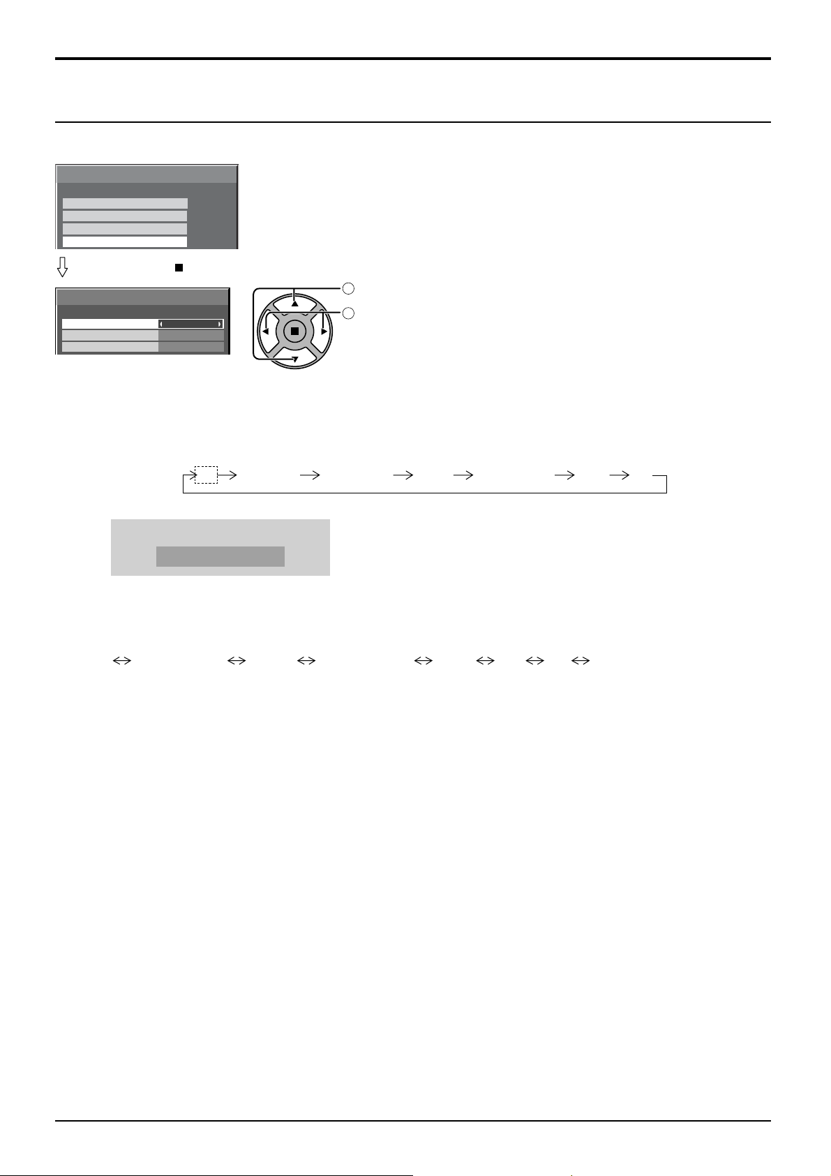
Options Adjustments
Input Search
When a signal is not detected, another input with a signal is automatically selected.
Options
Weekly Command Timer
Audio input select
Touch Panel settings
Input Search
Press ACTION ( ) button
Input Search
Input Search
Primary Input
Secondary Input
Input Search
Off: When there is no signal, the input is not switched automatically.
All Inputs: Searches all inputs and switches to an input with a signal.
Priority: Searches “Primary Input” and “Secondary Input” in order and switches to an input with a signal.
1/3
select
1
adjust
Off
2
Input search is executed in the following order.
(Example) When the current input is PC
PC VIDEO HDMI DVINETWORK COMPONENTSLOT INPUT
Searching...
“Searching...” is displayed during the input search.
Primary Input, Secondary Input
Set the input to search when “Priority” is selected.
(NONE) SLOT INPUT* VIDEO COMPONENT HDMI DVI PC NETWORK
* “SLOT INPUT” is displayed when an optional Terminal Board is installed.
When a Terminal Board with dual input terminals is installed, “SLOT INPUT A” and “SLOT INPUT B” are displayed.
Notes:
• This menu is available only when “Input lock” is “Off”. (see page 51)
• If the input is changed by this function, the last input is selected when the power is turned on next time.
If you wish to retain the original input when the power is turned on, set “Initial input” to the original input.
(see page 50)
57
Page 58
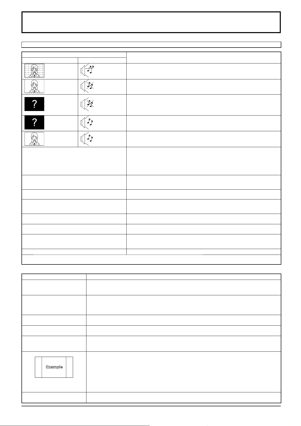
Troubleshooting
Before you call for service, determine the symptoms and make a few simple checks as shown below.
Symptoms
Picture Sound
Interference Noisy Sound
Normal Picture No Sound
No Picture No Sound
No Picture Normal Sound
No Colour Normal Sound
No remote control operations can be performed. Check whether the batteries have discharged completely and, if they have not,
A cracking sound is sometimes heard from the unit.
The top or bottom of the picture on the screen is cut
off when I use the zoom function.
Areas at the top and bottom of the screen where
the image is missing appear when I use the zoom
function.
I can hear sounds coming from inside the unit. When the power is turned on, a sound of the display panel being driven may be
Parts of the unit become hot.
Power automatically turns off unexpectedly. Check the settings of “PC Power management”, “DVI-D Power management”,
Power indicator is blinking in red.
This Plasma Display uses special image processing. Hence a slight time lag may occur between image and audio, depending on the
type of input signal. However, this is not a malfunction.
Electrical Appliances
Cars / Motorcycles
Fluorescent light
Volume
(Check whether the mute function has been activated on the remote control.)
Check if speakers are connected properly.
Not plugged into AC outlet
Not switched on
Picture and Brightness/Volume setting
(Check by pressing the power switch or stand-by button on the remote control.)
If a signal with a non-applicable colour system format, or frequency is input, only
the input terminal indication is displayed.
Colour controls set at minimum level (see page 26, 27)
Colour system (see page 47)
whether they were inserted properly.
Check whether the remote control sensor is exposed to an outdoor light or a
strong fl uorescent light.
Check whether the remote control designed specifi cally for use with the unit is
being used. (The unit cannot be operated by any other remote control.)
If there is nothing wrong with the picture or sound, this is the sound of the cabinet
undergoing very slight contractions in response to changes in the room temperature.
There are no adverse effects on the performance or other aspects.
Adjust the position of the picture on the screen.
When using a video software program (such as a cinema size program) with a
screen wider than one in the 16:9 mode, blank areas separate from the images
are formed at the top and bottom of the screen.
heard: This is normal and not indicative of malfunctioning.
Even when the temperature of parts of the front, top and rear panels has risen, these
temperature rises will not pose any problems in terms of performance or quality.
“No signal power off” and “No activity power off” in the Setup menu. Any of them
may be set to “On (Enable)”. (see page 42, 45)
There is possibility of malfunction. Please contact an Authorized Service Center.
Checks
Plasma Display panel
Symptoms Check
The screen darkens slightly
when bright pictures with minimal
movements are shown.
It takes a while for the picture
to appear.
The edges of the images
fl icker.
The brightness on both sides of
images in the 4:3 mode changes.
Some parts of the screen do
not light up.
Image retention appears
Whirring sounds can be heard
from the display unit.
58
The screen will darken slightly when photos, still images of a computer or other pictures with minimal
movements are shown for an extended period. This is done to reduce image retention on the screen
and the shortening of the screen’s service life: It is normal and not indicative of malfunctioning.
The unit digitally processes the various signals in order to reproduce esthetically pleasing images. As
such, it sometimes takes a few moments for the picture to appear when the power has been turned
on, when the input has been switched or when the images for the main picture and sub picture on
the two screens are swapped.
Due to the characteristics of the system used to drive the panel, the edges may appear to fl icker in
the fast-moving parts of the images: This is normal and not indicative of malfunctioning.
When viewing the side panels at the “High” or “Mid” setting, the brightness on both sides may change
depending on the kind of program shown: This is normal and not indicative of malfunctioning.
The plasma display panel is manufactured using an extremely high level of precision technology,
however, sometimes some parts of the screen may be missing picture elements or have luminous
spots. This is not a malfunction.
Do not allow a still picture to be displayed for an extended period, as this can cause a permanent
image retention to remain on the Plasma Display.
Examples of still pictures include logos, video games, computer images, teletext and images displayed
in 4:3 mode.
Note:
The permanent image retention on the Plasma Display resulting from fi xed image use is not an
operating defect and as such is not covered by the Warranty.
This product is not designed to display fi xed images for extended periods of time.
The display unit is fi tted with a cooling fan to dissipate heat generated during normal use. The whirring
sound is caused by rotation of the fan and is not a malfunction.
Page 59
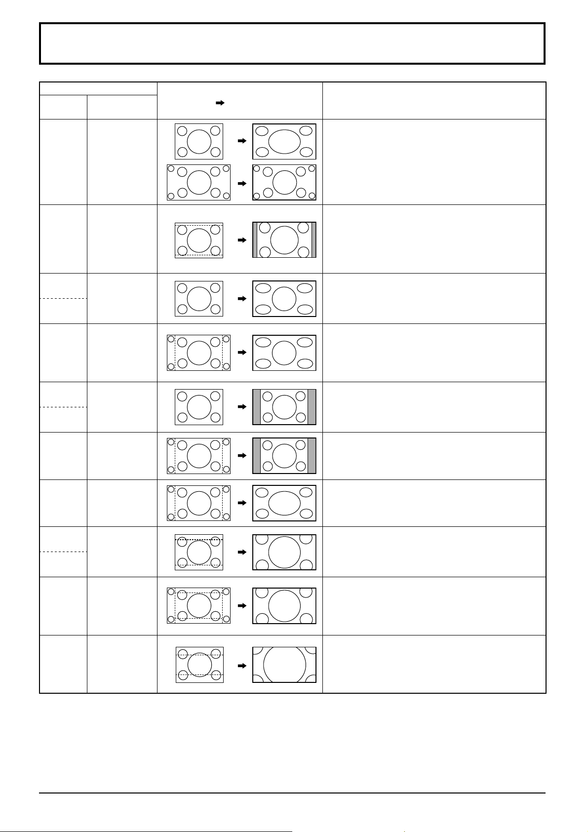
List of Aspect Modes
Aspect mode
All Aspect: OnFactory setting
All Aspect: Off
16:9 16:9
14:9 14:9
Just
Just
Just1
Just2 –
4:3
4:3
4:3 (1)
Picture
Enlarged screen
Description
The display of the pictures fi lls the screen.
In the case of SD signals, pictures with a 4:3 aspect
ratio are enlarged horizontally, and displayed. This
mode is suited to displaying anamorphic pictures with
a 16:9 aspect ratio.
Letterbox pictures with a 14:9 aspect ratio are enlarged
vertically and horizontally so that their display fi lls the
screen vertically and is slightly smaller than the screen
horizontally. The top and bottom edges of the pictures
are cut off. Side panels are displayed at the left and right
edges of the screen.
Pictures with a 4:3 aspect ratio are enlarged horizontally
so that the picture distortion is minimized. The display of
the areas around the left and right edges of the screen
is slightly elongated.
The pictures with a 4:3 aspect ratio among the 16:9 aspect
ratio signals are enlarged horizontally so that the picture
distortion is minimized. The left and right edges of the
pictures are cut off. The display of the areas around the
left and right edges of the screen is slightly elongated.
Pictures with a 4:3 aspect ratio are displayed with their
original aspect ratio. Side panels are displayed at the
left and right edges of the screen.
4:3 (2) –
4:3 Full 4:3 Full
Zoom
Zoom1
Zoom1
Zoom2 Zoom2
Zoom3 Zoom3
The pictures with a 4:3 aspect ratio among the 16:9
aspect ratio signals are displayed with their original
aspect ratio. The left and right edges of the pictures are
masked with side panels.
The pictures with a 4:3 aspect ratio among the 16:9
aspect ratio signals are enlarged horizontally so that
their display fi lls the screen. The left and right edges of
the pictures are cut off.
Letterbox pictures with a 16:9 aspect ratio are enlarged
vertically and horizontally so that their display fi lls the
screen. The top and bottom edges of the pictures are
cut off.
The letterbox pictures with a 2.35:1 aspect ratio among
the 16:9 aspect ratio signals are enlarged vertically and
horizontally so that their display fi lls the screen. The top
and bottom edges as well as the left and right edges of
the pictures are cut off.
Letterbox pictures with a 2.35:1 aspect ratio are enlarged
vertically and horizontally so that their display fi lls the
screen vertically and is slightly larger than the screen
horizontally. The top and bottom edges as well as the
left and right edges of the pictures are cut off.
59
Page 60
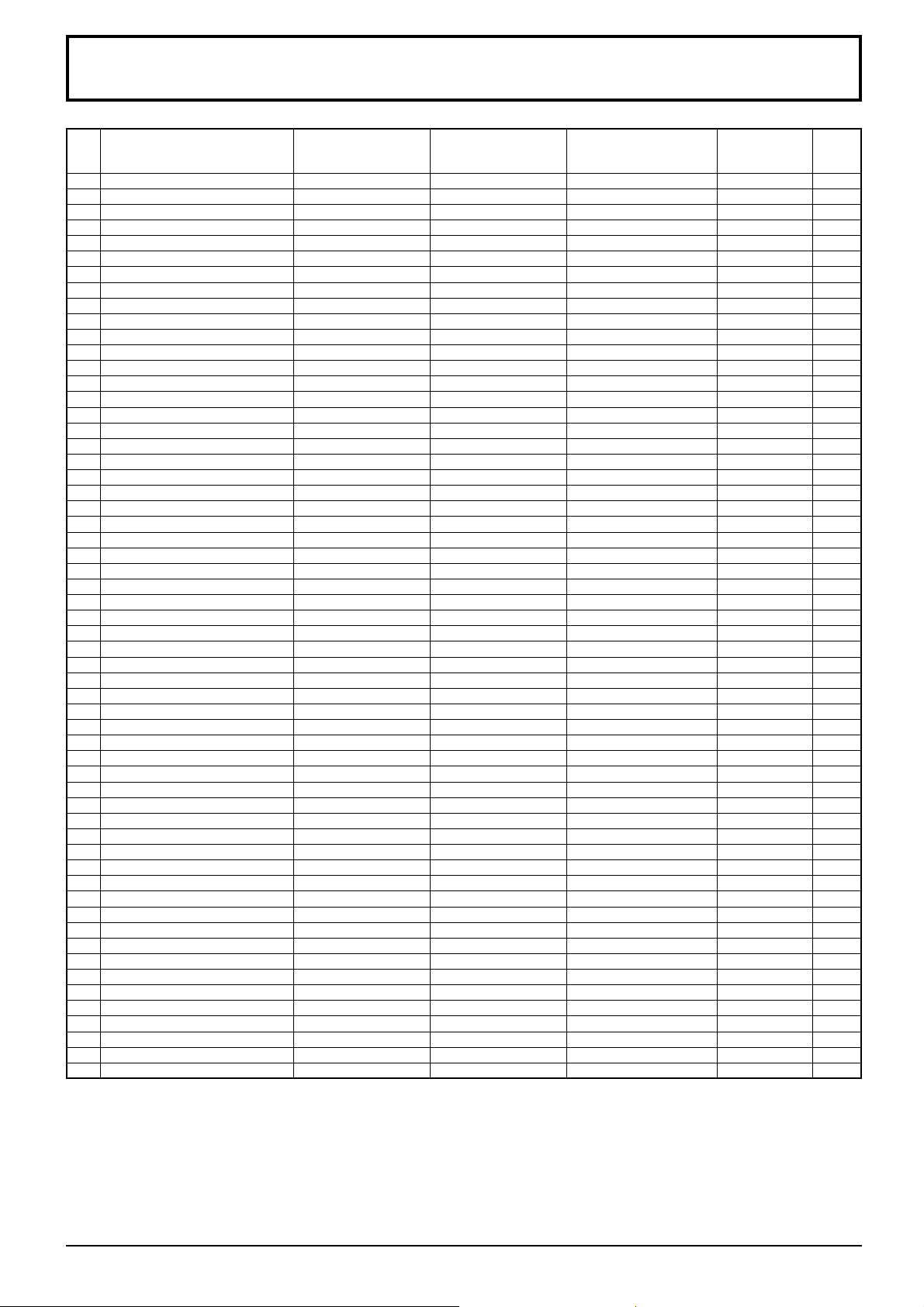
Applicable Input Signals
*Mark: Applicable input signal
Signal name
1 525 (480) / 60i 15.73 59.94 * (13.5) * (27.0) *
2 525 (480) / 60p 31.47 59.94 * (27.0)
3 625 (575) / 50i 15.63 50.00 * (13.5)
4 625 (576) / 50i 15.63 50.00 * (27.0) *
5 625 (575) / 50p 31.25 50.00 * (27.0)
6 625 (576) / 50p 31.25 50.00 * (27.0) *
7 750 (720) / 60p 45.00 60.00 * (74.25) * (74.25) *
8 750 (720) / 50p 37.50 50.00 * (74.25) * (74.25) *
9 1,125 (1,080) / 60p 67.50 60.00 * (148.5)
10 1,125 (1,080) / 60i 33.75 60.00 * (74.25)
11 1,125 (1,080) / 50p 56.26 50.00 * (148.5)
12 1,125 (1,080) / 50i 28.13 50.00 * (74.25)
13 1,125 (1,080) / 24sF 27.00 48.00 * (74.25)
14 1,125 (1,080) / 30p 33.75 30.00 * (74.25)
15 1,125 (1,080) / 25p 28.13 25.00 * (74.25)
16 1,125 (1,080) / 24p 27.00 24.00 * (74.25)
17 1,250 (1,080) / 50i 31.25 50.00 * (74.25)
18 2,048 × 1,080 / 24sF
19 2,048 × 1,080 / 24p
20 640 × 400 @70 Hz 31.46 70.07 * (25.17)
21 640 × 480 @60 Hz 31.47 59.94 * (25.18)
22 640 × 480 @72 Hz 37.86 72.81 * (31.5)
23 640 × 480 @75 Hz 37.50 75.00 * (31.5)
24 640 × 480 @85 Hz 43.27 85.01 * (36.0)
25 800 × 600 @56 Hz 35.16 56.25 * (36.0)
26 800 × 600 @60 Hz 37.88 60.32 * (40.0) * (40.0) *
27 800 × 600 @72 Hz 48.08 72.19 * (50.0)
28 800 × 600 @75 Hz 46.88 75.00 * (49.5)
29 800 × 600 @85 Hz 53.67 85.06 * (56.25)
30 852 × 480 @60 Hz 31.47 59.94 * (33.54)
31 1,024 × 768 @50 Hz 39.55 50.00 * (51.89) *
32 1,024 × 768 @60 Hz 48.36 60.00 * (65.0) * (65.0) *
33 1,024 × 768 @70 Hz 56.48 70.07 * (75.0)
34 1,024 × 768 @75 Hz 60.02 75.03 * (78.75)
35 1,024 × 768 @85 Hz 68.68 85.00 * (94.5)
36 1,066 × 600 @60 Hz 37.64 59.94 * (53.0) * (53.0) *
37 1,152 × 864 @60 Hz 53.70 60.00 * (81.62) *
38 1,152 × 864 @75 Hz 67.50 75.00 * (108.0)
39 1,280 × 768 @60 Hz 47.70 60.00 * (80.14)
40 1,280 × 800 @60 Hz (1) 49.31 59.91 * (71.0) * (71.0) *
41 1,280 × 800 @60 Hz (2) 49.70 59.81 * (83.5) * (83.5) *
42 1,280 × 960 @60 Hz 60.00 60.00 * (108.0)
43 1,280 × 960 @85 Hz 85.94 85.00 * (148.5)
44 1,280 × 1,024 @60 Hz 63.98 60.02 * (108.0) * (108.0) *
45 1,280 × 1,024 @75 Hz 79.98 75.03 * (135.0)
46 1,280 × 1,024 @85 Hz 91.15 85.02 * (157.5)
47 1,366 × 768 @50 Hz 39.55 50.00 * (69.92) *
48 1,366 × 768 @60 Hz 48.36 60.00 * (86.71) * (87.44) *
49 1,400 × 1,050 @60 Hz 65.22 60.00 * (122.61) *
50 1,440 × 900 @60 Hz (1) 55.47 59.90 * (88.75) * (88.75) *
51 1,440 × 900 @60 Hz (2) 55.93 59.89 * (106.5) * (106.5) *
52 1,600 × 1,200 @60 Hz 75.00 60.00 * (162.0) * (162.0) *
53 1,600 × 1,200 @65 Hz 81.25 65.00 * (175.5)
54 1,920 × 1,080 @60 Hz 67.50 60.00 * (148.5)
55 1,920 × 1,200 @60 Hz 74.04 59.95 * (154.0) *
56 Macintosh13” (640 × 480) 35.00 66.67 * (30.24)
57 Macintosh16” (832 × 624) 49.72 74.54 * (57.28)
58 Macintosh21” (1,152 × 870) 68.68 75.06 * (100.0)
∗1:
Based on SMPTE 274M standard.
∗2:
Based on SMPTE RP211 standard.
∗3:
Based on SMPTE 295M standard.
∗4:
The input signal is recognized as 1,125 (1,080) / 60p.
∗5:
When selected the RGB format and 525p signal input to the PC IN terminal, it is recognized as VGA 60Hz signal.
∗6:
When inputted VGA 60Hz format signal from the other than PC IN terminal, it is recognized as 525p signal.
Horizontal frequency
(kHz)
∗7 27.00 48.00
∗7 27.00 24.00
Vertical frequency
(Hz)
COMPONENT / RGB
IN / PC IN
(Dot clock (MHz))
∗7: Based on SMPTE 292M and 372M standards. These signals can be received when the Dual Link HD-SDI Terminal
Board (TY-FB11DHD) is installed.
Note: Signals without above specifi cation may not be displayed properly.
DVI-D IN
(Dot clock
(MHz))
HDMI
∗5 * (27.0) *
∗1 * (148.5) *
∗1 * (74.25) *
∗1 * (148.5) *
∗1 * (74.25) *
∗2
∗1 * (74.25)
∗1 * (74.25)
∗1 * (74.25) *
∗3
∗6 * (25.18) *
∗6*
(34.24) *
∗4 * (148.5) *
60
Page 61
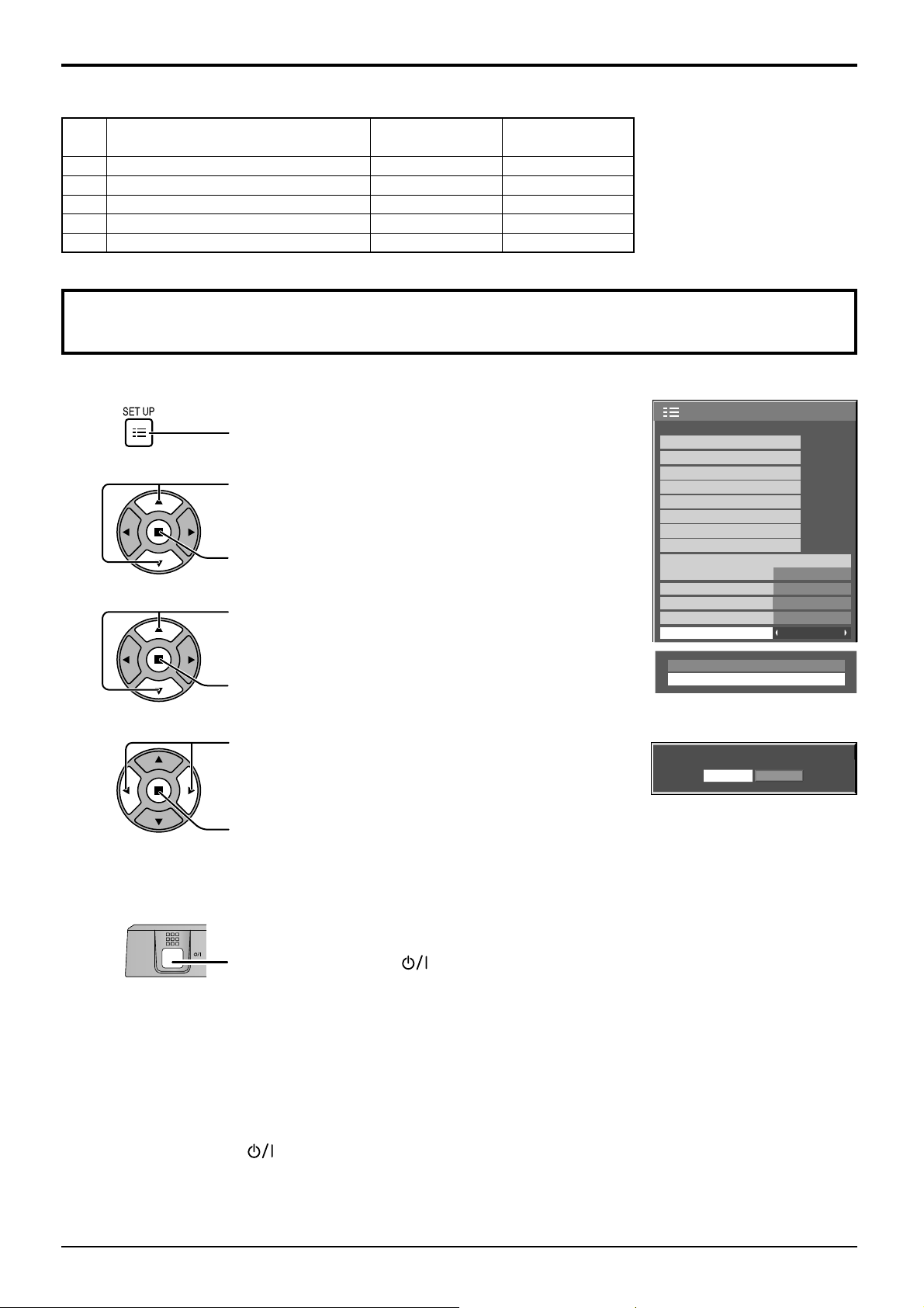
Video input (VIDEO)
Signal name
1 NTSC 15.73 59.94
2 PAL 15.63 50.00
3 PAL60 15.73 59.94
4 SECAM 15.63 50.00
5 Modifi ed NTSC 15.73 59.94
Horizontal Vertical
frequency(kHz) frequency(Hz)
Shipping condition
This function allows you to reset the unit to the factory setting.
Applicable Input Signals
1
2
3
4
Press to display the Setup menu.
Press to select “OSD Language”.
Press for more than 3 seconds.
Press to select “Shipping”.
Press to display the Shipping menu.
Press to select “YES”.
Press to confi rm.
Setup
Touch-Pen Settings
MULTI PIP Settings
Signal
Screensaver
Extended life settings
ECO Mode settings
Input label
Function Button Settings
Component/RGB-in select
No activity power off
Menu Display Duration
OSD Brightness
OSD Language English (UK
Options
Shipping
Shipping
YES NO
RGB
Disable
30 S
5
1/2
)
5
Wait for 10 seconds.
6
Press the power switch ( ) on main unit to turn the power off.
[from the unit]
1 Press the MENU button till the Setup menu is displayed.
2 Press the Volume Up“+” or Down“–” button to select “OSD Language”.
3 Press and hold the ENTER button till the Shipping menu is displayed.
4 Press the Volume Up“+” or Down“–” button to select “YES”.
5 Press the ENTER button and wait for 10 sec.
6 Press the power switch (
) on main unit to turn the power off.
61
Page 62
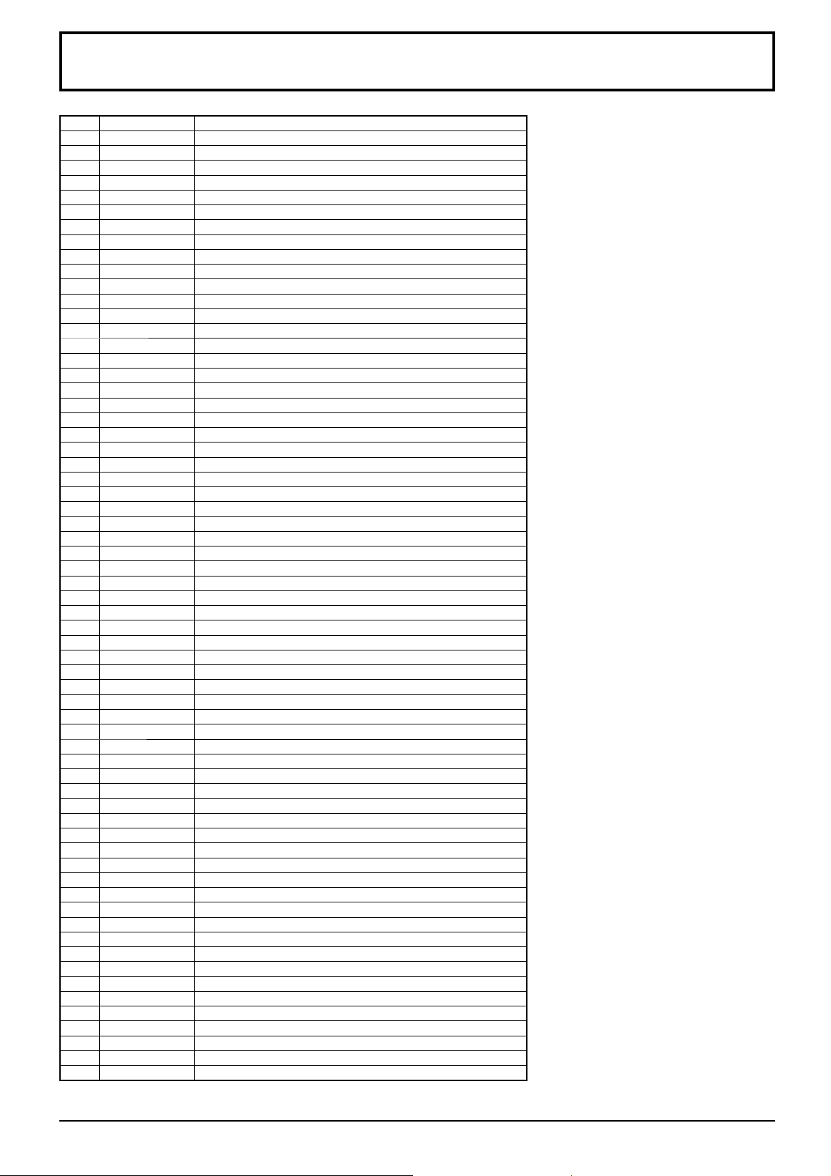
Command list of Weekly Command Timer
No. Command Control details
1 AAC:MENCLR Audio Menu (Clear)
2 AAC:MENDYN Audio Menu (Dynamic)
3 AAC:MENSTD Audio Menu (Standard)
4 AAC:SURMON Surround (ON)
5 AAC:SUROFF Surround (OFF)
6 AMT:0 Audio Mute (OFF)
7 AMT:1 Audio Mute (ON)
8 ASO:M Audio out when PIP mode (Main Picture)
9 ASO:S Audio out when PIP mode (Sub Picture)
10 AVL:00 Audio Volume (00)
11 AVL:10 Audio Volume (10)
12 AVL:20 Audio Volume (20)
13 AVL:30 Audio Volume (30)
14 AVL:40 Audio Volume (40)
15 AVL:50 Audio Volume (50)
16 AVL:60 Audio Volume (60)
17 DAM:FULL Aspect (16:9)
18 DAM:JUST Aspect (Just)
19 DAM:NORM Aspect (4:3)
20 −−
21 DAM:ZOOM Aspect (Zoom)
22 DWA:OFF Dual Picture mode (OFF)
23 ISS:SL1 Sub Picture Input Select (SLOT INPUT)
24 ISS:NW1 Sub Picture Input Select (NETWORK)
25 IMS:WB1 Input select (WHITEBOARD) (Main Picture when PIP mode)
26 −−
27 −−
28 −−
29 −−
30 −−
31 DWA:PIN0 The location of the sub picture (lower right)
32 DWA:PIN1 The location of the sub picture (lower left)
33 DWA:PIN2 The location of the sub picture (upper left)
34 DWA:PIN3 The location of the sub picture (upper right)
35 DWA:PIP Dual Picture mode (Picture in Picture)
36 −−
37 DWA:SWP Swap main picture and sub picture when PIP mode
38 −−
39 IMS:SL1 Input select (SLOT INPUT) (Main Picture when PIP mode)
40 IMS:S1A Input select (SLOT INPUT A) (Main Picture when PIP mode)
41 IMS:S1B Input select (SLOT INPUT B) (Main Picture when PIP mode)
42 IMS:VD1 Input select (VIDEO) (Main Picture when PIP mode)
43 IMS:YP1 Input select (COMPONENT) (Main Picture when PIP mode)
44 IMS:HM1 Input select (HDMI) (Main Picture when PIP mode)
45 IMS:DV1 Input select (DVI) (Main Picture when PIP mode)
46 IMS:PC1 Input select (PC) (Main Picture when PIP mode)
47 IMS:NW1 Input select (NETWORK) (Main Picture when PIP mode)
48 ISS:S1A Sub Picture Input Select (SLOT INPUT A)
49 ISS:S1B Sub Picture Input Select (SLOT INPUT B)
50 ISS:VD1 Sub Picture Input Select (VIDEO)
51 ISS:YP1 Sub Picture Input Select (COMPONENT)
52 ISS:HM1 Sub Picture Input Select (HDMI)
53 ISS:DV1 Sub Picture Input Select (DVI)
54 ISS:PC1 Sub Picture Input Select (PC)
OSP:SCR0 Screen Saver Scrolling bar only (OFF)
55
OSP:SCR1 Screen Saver Scrolling bar only (ON)
56
57 POF Power OFF
58 PON Power ON
SSC:FNC0 Screen Saver function (Scrolling bar only)
59
SSC:FNC1 Screen Saver function (Negative image)
60
SSC:MOD0 Screen Saver (Mode (OFF))
61
SSC:MOD3 Screen Saver (Mode (ON))
62
63
64
VMT:0
VMT:1
∗
∗
Picture Mute (OFF)
Picture Mute (ON)
Picture Mute cannot be unlocked
∗
by powering off/on with the remote
control. Turn off and on again with
the button on the unit or enter the
command VMT:0 to unlock Picture
Mute.
62
Page 63
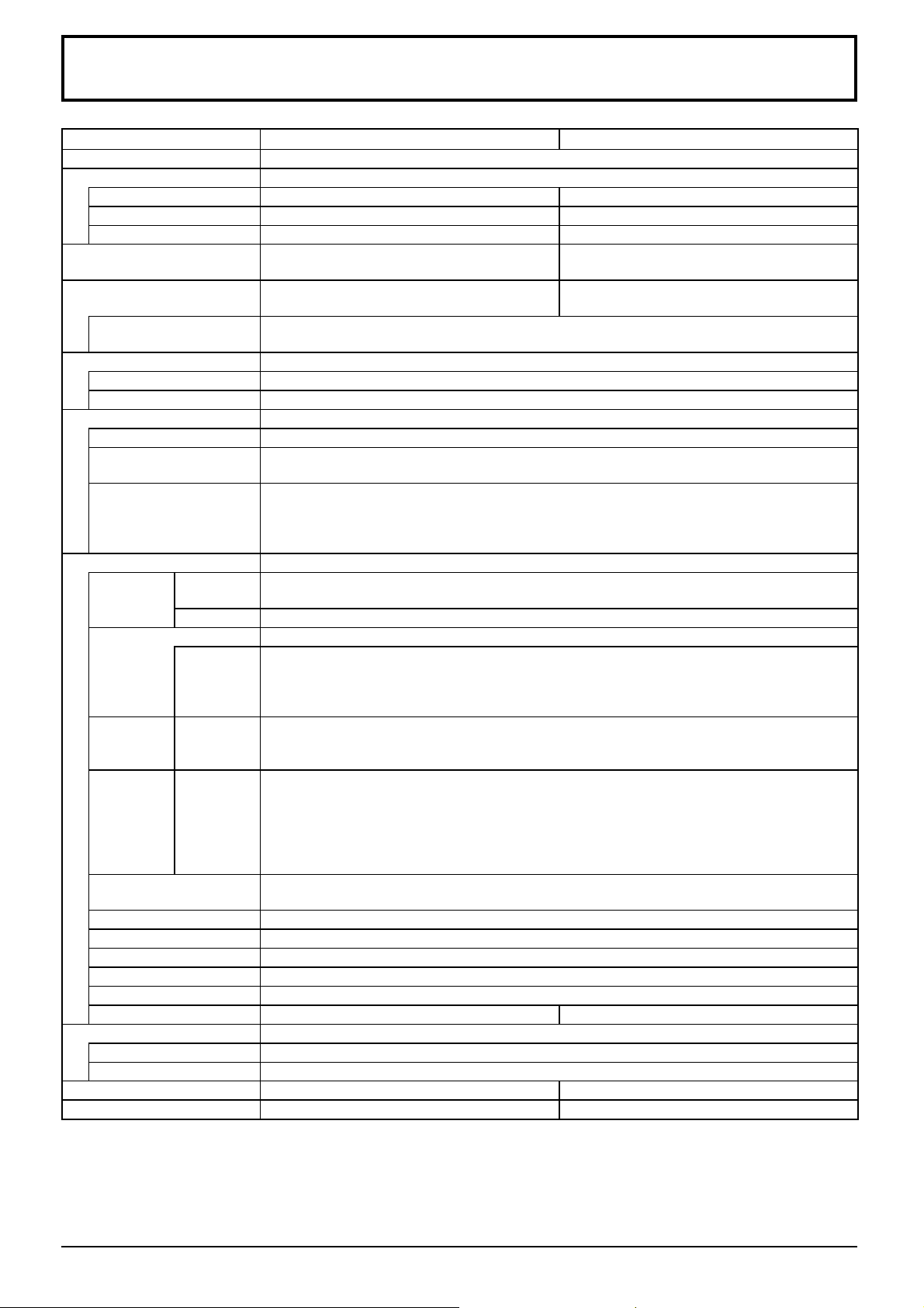
Specifi cations
TH-50PB2W TH-65PB2W
Power Source 220 - 240 V AC, 50/60 Hz
Power Consumption
Power on 375 W 515 W
Stand-by condition 0.5 W 0.5 W
Power off condition 0.3 W 0.3 W
Plasma Display panel Drive method : AC type 50-inch,
16:9 aspect ratio
Screen size 1,105 mm (W) × 622 mm (H)
× 1,268 mm (diagonal)
(No.of pixels) 2,073,600 (1,920 (W) ×1,080 (H))
[5,760 × 1,080 dots]
Operating condition
Temperature 0 °C - 40 °C
Humidity 20 % - 80 %
Applicable signals
Colour System NTSC, PAL, PAL60, SECAM, Modifi ed NTSC
Scanning format 525 (480) / 60i · 60p, 625 (575) / 50i · 50p, 750 (720) / 60p · 50p, 1125 (1080) / 60i · 60p · 50i ·
50p · 24p · 25p · 30p · 24sF, 1250 (1080) / 50i
PC signals VGA, SVGA, XGA, SXGA
UXGA ···· (compressed)
Horizontal scanning frequency 15 - 110 kHz
Vertical scanning frequency 48 - 120 Hz
Connection terminals
AV IN VIDEO
AUDIO 1 IN
HDMI TYPE A Connector
COMPONENT/RGB IN
Y/G
P
B/CB/B
P
R/CR/R
AUDIO 1 IN
DVI-D IN
AUDIO 2 IN
PC IN
AUDIO 2 IN
SERIAL External Control Terminal
PEN ADAPTER For electronic pen adapter
MEMORY/(CHARGE) For USB memory/electronic pen charging
CHARGE For electronic pen charging
WIRELESS MODULE for Wireless module (ET-WM200E)
LAN RJ45 10BASE-T/100BASE-TX, compatible with PJLink™
EXP SP 6 Ω, 16 W [8 W + 8 W] (10 % THD) 8 Ω, 20 W [10 W + 10 W] (10 % THD)
Sound
Speakers 120 mm × 40 mm × 2 pcs
Audio Output 20 W [10 W + 10 W] (10 % THD)
Dimensions (W × H × D) 1,210 mm × 724 mm × 89 mm 1,554 mm × 925 mm × 99 mm
Mass (weight) approx. 34.0 kg net approx. 58.0 kg net
BNC
Stereo mini jack (M3) × 1
BNC
BNC
BNC
Stereo mini jack (M3) × 1
DVI-D 24 Pin
Content Protection
Stereo mini jack (M3) × 1
High-Density Mini D-sub 15 Pin
Stereo mini jack (M3) × 1
D-sub 9 Pin RS-232C compatible
1.0 Vp-p (75 Ω)
0.5 Vrms, Shared with COMPONENT/RGB IN
with sync 1.0 Vp-p (75 Ω)
0.7 Vp-p (75 Ω)
0.7 Vp-p (75 Ω)
0.5 Vrms, Shared with VIDEO
Compliance with DVI Revision 1.0
Compatible with HDCP 1.1
0.5 Vrms, Shared with PC IN
Y or G with sync 1.0 Vp-p (75 Ω)
Y or G without sync 0.7 Vp-p (75 Ω)
P
P
HD/VD: 1.0 - 5.0 Vp-p (high impedance)
0.5 Vrms, Shared with DVI-D IN
Drive method : AC type 65-inch,
16:9 aspect ratio
1,434 mm (W) × 806 mm (H)
× 1,645 mm (diagonal)
B/CB/B: 0.7 Vp-p (75 Ω)
R/CR/R: 0.7 Vp-p (75 Ω)
Note:
Design and specifi cations are subject to change without notice. Mass and dimensions shown are approximate.
63
Page 64
This product incorporates the following software:
(1) the software developed independently by or for Panasonic Corporation,
(2) the software owned by third party and licensed to Panasonic Corporation,
(3) the software licensed under the GNU General Public License, Version 2.0 (GPL-2.0),
(4) the software licensed under the GNU LESSER General Public License, Version 2.1 (LGPL-2.1) and/or,
(5) open source software licensed under the MIT License.
(6) open source software other than the software licensed under the GPL and/or LGPL.
For the software categorized as (3) and (4), please refer to the terms and conditions of GPL-2.0 and LGPL-2.1, as
the case may be at
http://www.gnu.org/licenses/old-licenses/gpl-2.0.html and
http://www.gnu.org/licenses/old-licenses/lgpl-2.1.html
The GPL/LGPL/MIT software is distributed in the hope that it will be useful, but WITHOUT ANY WARRANTY, without
even the implied warranty of MERCHANTABILITY or FITNESS FOR A PARTICULAR PURPOSE.
At least three (3) years from delivery of products, Panasonic will give to any third party who contact us at the contact
information provided below, for a charge no more than our cost of physically performing source code distribution, a
complete machine-readable copy of the corresponding source code and the copyright notice, covered under
GPL-2.0/LGPL-2.1.
Contact Information
[email protected]
For the software categorized as (6) includes as follows.
1. The software developed by the OpenSSL Project for use in the OpenSSL Toolkit. (http://www.openssl.org/)
2. The software developed by the University of California, Berkeley and its contributors.
3. FreeType code.
4. The Independent JPEG Group's JPEG software.
5. thttpd code.
Customer’s Record
The model number and serial number of this product can be found on its rear panel. You should note this serial
number in the space provided below and retain this book, plus your purchase receipt, as a permanent record of your
purchase to aid in identifi cation in the event of theft or loss, and for Warranty Service purposes.
Model Number Serial Number
Web Site : http://panasonic.net
© Panasonic Corporation 2013
 Loading...