

Page 1

IDTV
REC
VCR DVD
VCR
TEXT
N
MODE
EXIT
TV/AVGUIDE
STTL INDEX HOL
D
1 2 3
4 5
6
7 8
9
C
0
PROGRAMME
DIRECT
TV RE
C
DVB
Analogue
ASPECT
MENU
OK
Operating Instructions
Information on Disposal for Users of Waste Electrical & Electronic Equipment
(private households)
This symbol on the products and/or accompanying documents means that used electrical and
electronic products should not be mixed with general household waste.
For proper treatment, recovery and recycling, please take these products to designated collection
points, where they will be accepted on a free of charge basis. Alternatively, in some countries you
may be able to return your products to your local retailer upon the purchase of an equivalent new
product.
Disposing of this product
correctly will help to save valuable resources and prevent any potential negative
effects on human health and the environment which could otherwise arise from inappropriate
waste handling. Please contact your local authority for further details of your nearest designated collection point.
Penalties may be applicable for incorrect disposal of this waste, in accordance with national legislation.
For business users in the European Union
If you wish to discard electrical and electronic equipment, please contact your dealer or supplier for further
information.
Information on Disposal in other Countries outside the European Union
This symbol is only valid in the European Union.
If you wish to discard this product, please contact your local authorities or dealer and ask for the correct method of
disposal.
Plasma Television
Model No. TH-37PX60E
TH-42PX60E
Customer’s Record
The model number and serial number of this product may be found on its rear panel. You should note this serial
number in the space provided below and retain this book, plus your purchase receipt, as a permanent record
of your purchase to aid in identification in the event of theft or loss, and for Warranty Service purposes.
Model Number Serial Number
Matsushita Electric Industrial Co., Ltd.
Web Site : http://www.panasonic-europe.com
2006 Matsushita Electric Industrial Co., Ltd. All Rights Reserved.
Printed in Czech Republic
This TV is designed to be used in Germany and France.
English
Please read these instructions before operating your set and retain them for future reference.
The images shown in this manual are for illustrative purposes only.
Page 2

2
3
Viewing Advanced FAQs, etc.Quick Start Guide
Turn your own living room into a movie theatre!
Experience an amazing level of multi-
media excitement
Enjoy rich multi-media
Camcorder
Personal
computer
Set top box
DVD recorder
Amplifier with
Speaker system
VCR
DVD player
Contents
Be Sure to Read
Safety Precautions ······································ 4
•
(Warning / Caution)
Notes ···························································5
•
Maintenance ··············································· 5
•
Quick Start Guide
Accessories / Options
Identifying Controls
Connection
Auto Setup
Enjoy your TV!
Basic Features
Watching TV ·············································· 10
•
Viewing Teletext ········································12
•
Watching Videos and DVDs ······················ 14
································ 8
································· 9
·········· 6
··············· 7
•
Advanced Features
How to Use Menu Functions ····················· 16
•
(picture, sound quality, etc.)
Advanced DVB Settings (DVB) ················· 18
•
(pay-TV, time, etc.)
Editing and Setting Channels (Analogue)
•
Editing and Setting Channels (DVB) ········· 22
•
Displaying PC Screen on TV ····················· 25
•
External Equipment ··································· 26
•
(Q-Link / Control with HDMI / Connections)
FAQs, etc.
Technical Information ································32
•
FAQs ························································· 36
•
Licence ······················································ 39
•
Specifications ············································ 39
•
····20
Page 3
Safety Precautions
4 : 3
Notes
Warning Caution
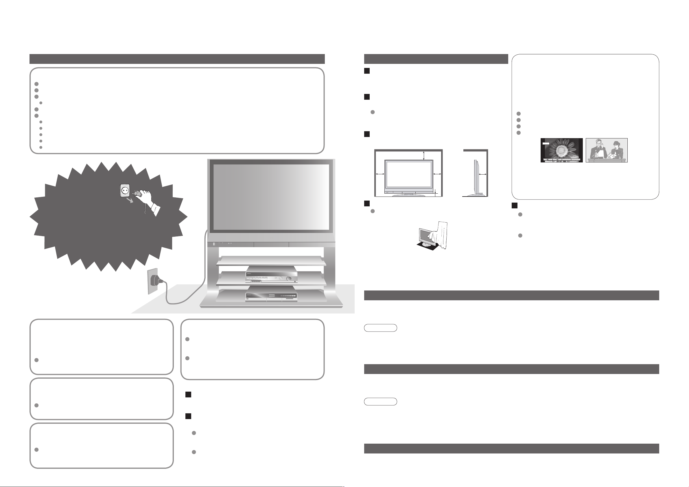
Handling the mains plug and lead
Insert the mains plug fully into the socket outlet. (If the mains plug is loose, it could generate heat and cause fire.)
Ensure that the mains plug is easily accessible.
Ensure the grounding pin on the mains plug is securely connected to prevent electrical shock.
An apparatus with CLASS I construction shall be connected to a mains socket outlet with a protective earthing connection.
Do not touch the mains plug with a wet hand. (This may cause electrical shock.)
Do not damage the mains lead. (A damaged lead may cause fire or electrical shock.)
Do not move the TV with the lead plugged in the socket outlet.
Do not place a heavy object on the lead or place the lead near a high-temperature object.
Do not twist the lead, bend it excessively, or stretch it.
Do not pull on the lead. Hold onto the mains plug body when disconnecting lead.
Do not use a damaged mains plug or socket outlet.
If you find any
abnormality, remove
the mains plug immediately!
(such as strange smell or smoke)
When cleaning the TV unit, remove the
mains plug
(Cleaning an energized unit may cause electrical shock.)
When TV will not be used for a long
time, remove the mains plug
This TV will still consume some power even in
the Off mode, as long as the mains plug is still
connected to a live socket outlet.
Allow sufficient space around the unit
for radiated heat
10
10
10
7
6
(cm)
Do not block the rear air vents
Blocked ventilation by curtains, etc. may cause
overheating, fire or electrical shock.
Remember not to keep still pictures on
the screen for extended lengths of time
Such still pictures cause after-images on the plasma
screen if they are displayed for a long time. These
after-images are not considered malfunctions and are
not covered by the warranty.
Typical still images
Channel number and unique logos
Image displayed in 4:3 mode
Video game
Computer image
12
To decrease the chance of after-images, a screen saver will
be automatically activated after a few minutes if there is no
signal and if there is no operation in AV mode. (p. 37)
The screen saver will be automatically deactivated when a
signal is detected or an operation is executed.
Keep the unit away from these equipment
Electronic equipment
In particular, do not place video equipment near the unit
(electromagnetic interference may distort images / sound).
Equipment with an infrared sensor
This TV also emits infrared rays (this may affect
operation of other equipment).
AC 220-240 V
50 / 60 Hz
Maintenance
First, remove the mains plug from the socket outlet.
Display panel
Daily care: Gently wipe the surface clean of dirt by using a soft cloth.
Major contamination: Wipe the surface clean using a soft cloth dampened with clean water or water containing a
small amount of neutral detergent. Then, using a soft dry cloth, evenly wipe the surface clean until it is dry.
Do not remove covers
NEVER modify the unit yourself
(High-voltage components may cause serious
electrical shock.)
Have the unit checked, adjusted, or repaired at
your local Panasonic dealer.
Keep liquids away from the TV
To prevent damage which may result in fire or
shock hazard, do not expose this appliance to
dripping or splashing.
Do not place containers with water (flower vase,
cups, cosmetics, etc.) above the set. (including on
shelves above, etc.)
Do not place foreign objects
inside the unit
Do not let metal or flammable objects drop into the unit
through the air vents (fire or electrical shock may result).
Do not expose to direct sunlight
and other sources of heat
Avoid exposing the TV set to direct sunlight and other
sources of heat. To prevent fire never place any type
of candle or naked flame on top or near the TV set.
Do not place the TV on an unstable
surface
Use only the dedicated stands /
mounting
Using an unauthorized stand or other fixtures may
make the unit shaky, risking injury. Be sure to ask
your local Panasonic dealer to perform setup.
Use optional stands / mounts (p. 6).
equipment
Caution
The surface of the display panel has been specially treated and may be easily damaged.
•
Do not tap or scratch the surface with your fingernail or other hard object.
Use care not to subject the surface to bug repellent, solvent, thinner, or other volatile substances
•
(this may degrade surface quality).
Cabinet
Daily care: Wipe the surface clean using a soft dry cloth.
Major contamination: Dampen a soft cloth with clean water or water containing a small amount of neutral detergent.
Then, wring the cloth and wipe the surface clean with it. Finally, wipe the surface clean with a dry cloth.
Caution
Use care not to subject the TV unit's surfaces to detergent.
•
(A liquid inside the TV unit could lead to product failure.)
Use care not to subject surfaces to bug repellent, solvent, thinner, or other volatile substances
•
(this may deteriorate the surface by peeling the paint).
Do not allow the cabinet to make contact with a rubber or PVC substance for a long time.
•
Mains plug
Wipe the mains plug with a dry cloth at regular intervals. (Moisture and dust may lead to fire or electrical shock.)
4 5
Page 4
6
7
Quick Start Guide
AV4
S-V V L R
+
-
-
+
IDTV
REC
VCR DVD
VCR
TEXT
N
MODE
EXIT
TV/AVGUIDE
STTL INDEX HOLD
1 2 3
4 5 6
7 8
9
C
0
PROGRAMME
DIRECT
TV REC
DVB
Analogue
ASPECT
MENU
OK
1 2 3
4 5 6
7 8 9
0
OK
C
IDTV
N
MODE
Identifying ControlsAccessories / Options
(
)
()(
)
(
)
(
)
(
)
(
)
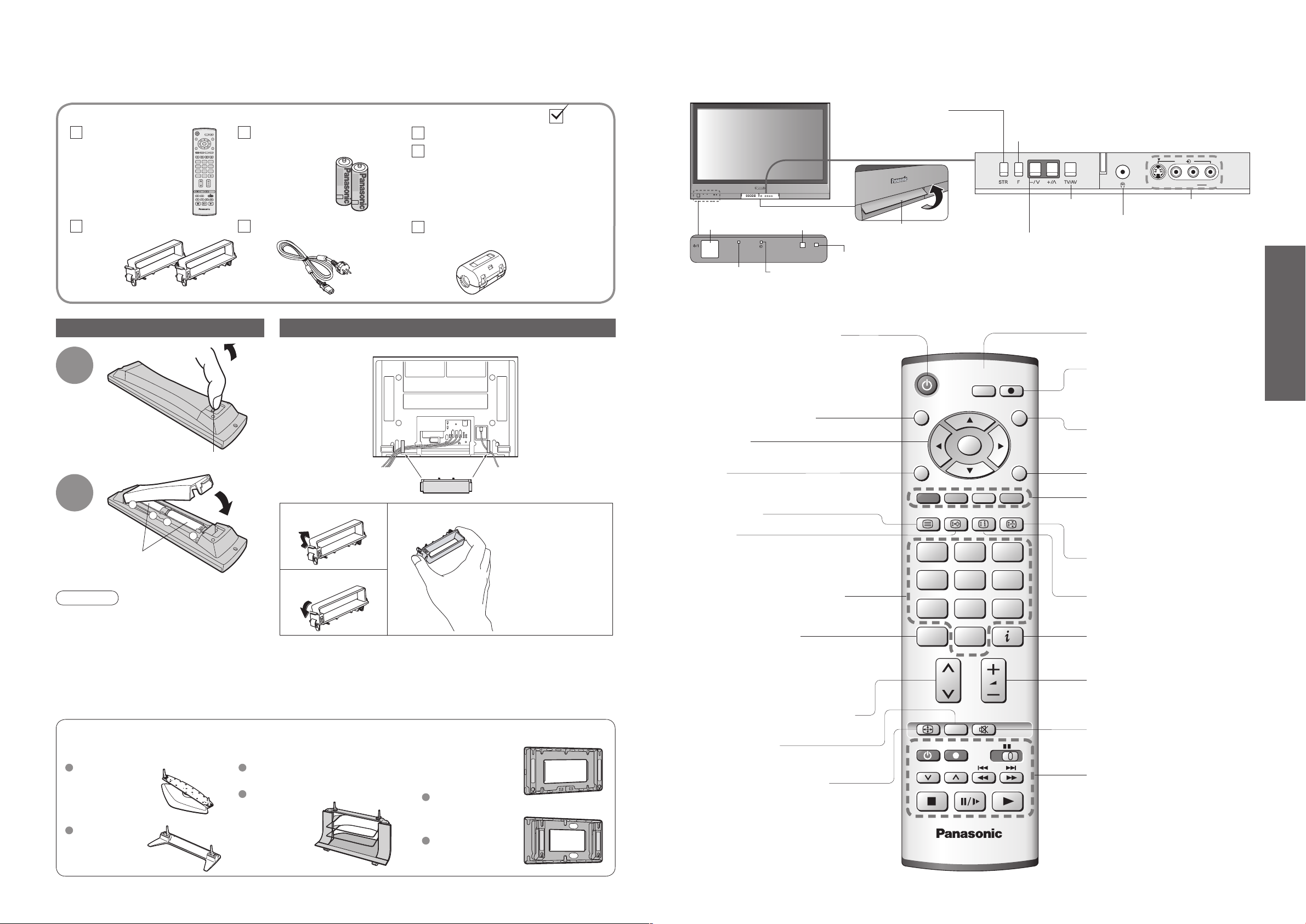
Standard accessories
Remote Control
Transmitter
EUR7651080
•
Clamper (2)
Installing remote's batteries
1
2
Note the correct
polarity (+ or -)
Caution
Incorrect installation may cause battery
•
leakage and corrosion, resulting in
damage to the remote control unit.
Do not mix old and new batteries.
•
Do not mix different battery types (such as
•
alkaline and manganese batteries).
Do not use rechargeable (Ni-Cd) batteries.
•
Do not burn or breakup batteries.
•
Optional accessories
Pedestal Plasma TV stand Wall-hanging
TY-ST42P600W TY-S37PX60W
TY-ST42P60W
Hook
Check that you have the accessories and items shown
Batteries for the Remote
Control Transmitter
R6 (UM3)
•
Mains Lead
(2)
Operating Instructions
Pan European Guarantee Card
Ferrite core
J0KF00000018
•
Attaching the cable clampers
Rear of the TV
Pull
open
Close
Snap open
Snap shut
Do not bundle the RF cable and mains lead together (could cause
•
distorted image).
Fix cables with clampers as necessary.
•
When using the optional accessory, follow the option’s assembly
•
manual to fix cables.
(TH-37PX60E)
TY-S42PX60W
(TH-42PX60E)
Remove from the TV unit
bracket
(vertical)
TY-WK42PV3W
(angle)
TY-WK42PR2W
Push both side
hooks and pull out
On / Off
switch
(standby: red)
Switches TV to On or Standby
(On / Off switch in On position)
Programme Guide (p. 10)
Select / OK
MENU
Press to access the Picture, Sound and
Setup menus
Teletext (p. 12)
Subtitles
Showing subtitles (p. 11) (DVB)
Viewing a favourite teletext
channel (p. 12)
Changes programme / channel
(p. 10)
Direct channel access
During normal TV viewing or when in the
Tuning, Programme edit or Manual tuning
menus, press and then enter channel number
using the numeric buttons
Press twice to change to the Cableband mode
Selects programmes in sequence
Normalizes (p. 16)
(Resets settings)
Changes aspect ratio (p. 11)
Store setting (p. 20)
Used to store tuning and
other function settings
Remote control
signal receiver
DVB lampPower lamp
DVB system active during
Direct TV Recording (Standby) :orange (flash)
Tuner Lock On (Standby) :orange
Swing up the door at "PULL".
C.A.T.S. (Contrast Automatic Tracking System) sensor
(senses brightness to adjust picture quality in "Auto" viewing mode) (p. 16)
Function
select
Selects programmes in sequence
Volume / Contrast / Brightness / Colour / Sharpness
/ Tint (NTSC mode) / Bass / Treble / Balance /
Tuning mode (analogue mode) (p. 20)
Switches TV/AV
Headphones jack (p. 30)
Switches DVB (digital broadcasting)
/ Analogue mode
DIRECT TV Recording
To immediately record programme
in VCR / DVD recorder with Q-Link
connection
(p. 26)
Switches TV/AV
(To watch videos or DVDs) (p. 14)
EXIT (Returns to TV screen)
Coloured buttons
(used for various functions)
(for example, see p. 12)
Still Picture (p. 11)
Teletext Index (p. 12)
Programme Information (p. 11)
Volume
Sound mute On / Off
VCR / DVD operations (p. 15)
AV4 terminals (p. 30)
(p. 10)
•
•
Identifying Controls
Accessories / Options
Page 5

8
9
Quick Start Guide
IDTV
VCR
EXIT
1 2 3
4 5
6
7 8 9
0
OK
AV2 AV3
RF OUT
RF IN
Exit
Adjust
Select
Return
Bass
Tr
eble
Balance
Headphone volume
MPX
Mode
Ambience
Sound menu
No service
Music
Off
DOWNLOAD IN PROGRESS
PLEASE WAIT
Programme : 63
Remote control unavailable
red
Auto SetupConnection
Start ATP Abbruch
Deutschland
France
Land
Please Wait !
DVB Auto Setup
Prog. Channel Service Name NetID. TS ID. Quality
This will take about 3 mins.
Exit
4
5
6
7
8
34
54
54
54
54
12302
12302
12302
12302
12302
4158
4158
4158
4158
4158
9
9
9
9
9
VOX
N24
ProSieben
KABEL
1
SAT.1
69 5
External equipments and cables shown in this manual are not supplied with this TV.
Please ensure that the unit is disconnected from the mains before attaching or disconnecting any leads.
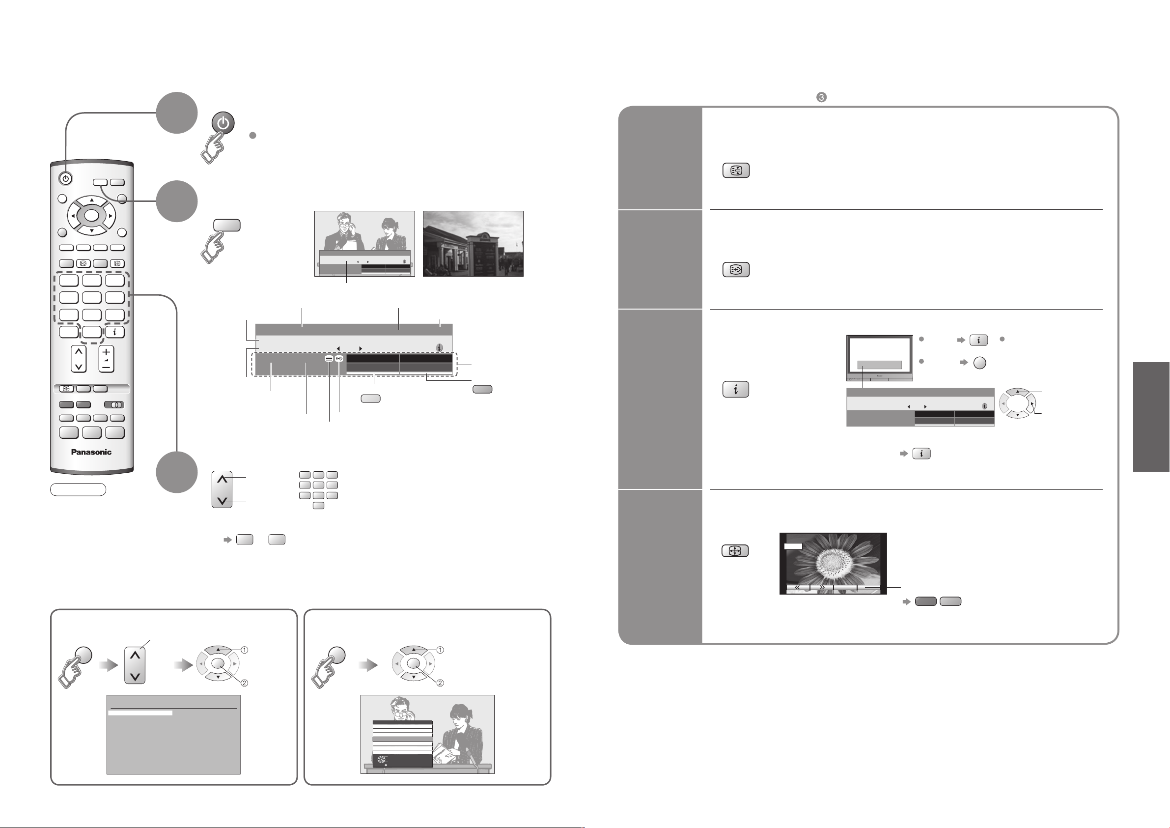
Watching TV
■
VHF / UHF aerial
Rear of the TV
Rear terminal portion
(enlarged view)
Fastener
To unfasten
•
Search and store TV channels automatically.
These steps are not necessary if the setup has been completed your local dealer.
1
2
Turn the TV On with the On / Off switch
You can now use the remote
•
control to turn On the unit or
turn the unit to standby mode.
(Power lamp: On)
Select your country
select
•
•
Auto Setup
Connection
Connect to AV2
•
or AV3 for a unit
supporting
Q-Link (p. 26).
SCART cable
(fully wired)
To record TV
■
programmes
DVD Recorder or VCR
Start Auto Setup
3
Auto Setup will start to search
•
for TV channels and store them.
Mains lead
(Connect after all the other connections.)
Need help
with operations?
(example: Sound menu)
RF cable
On-screen operation
guide will help you.
Auto Setup is now
complete and your
TV is ready for viewing.
If Q-Link (p. 26) equipment is
•
connected, analogue channel
information is automatically
downloaded to the equipment.
To check programme list
•
at-a-glance
Programme Guide (p. 10)
To edit channels
•
"Editing and Setting Channels"
(p. 20-24)
Page 6
10
11
Viewing
OK
OK
Lot ti au f d er Fl uch t
20: 00
-
20 :5 5
For i nfo pr ess
1 Das Erste
20:30
All S erv ice s
Pro fi le
ger
Mul ti Au di
o
Now
9
IDTV
VCR
MODE
EXIT
GUIDE
STTL HOLD
1 2 3
4 5
6
7 8 9
C
0
DVB
Analogue
ASPECT
OK
GUIDE
VCR
1 2 3
4 5
6
7 8
9
0
MODE
DVB
A
nalogue
Watching TV
HOLD
STTL
Lo tti a uf d er F lu ch t
20 :00
-
2 0:5 5
Fo r i nf o pr es s
1 Das Erste
20:30
Al l S er vi ce s
Pr ofi le
ge r
Mu lti A ud i
o
Now
EXIT
14 : 9
A
SPECT
red
green
(
)
Multi- A u d i o TXT
Subtit l e
Lotti a u f d e r F l u c h t
20:00 - 20:55
For in f o p r e s s
1 Das Erste
20:30
All Se r v i c e s
Profil e
ger
Encrypted No Signal
Multi A u d i o
Now
GUIDE
Analogue Programme Guide
Prog. Name Chan.
VCR :
1 :
2 :
3 :
4 :
5 :
6 :
7 :
8 :
9 :
10 :
11 :
12 :
CH21
CH44
CH51
CH41
CH47
CH23
CH26
CH58
-
-
-
-
-
Das Erste
ZDF
RT
L
Prog. Name Chan.
13 :
14 :
15 :
16 :
17 :
18 :
19 :
20 :
21 :
22 :
23 :
24 :
-
-
-
-
-
-
-
-
-
-
-
-
yellow
blue
All Services
CBBC Channel
BBC Radio Wales
BBC Radio Cymru
ZDF
Info/3sat
Doku/KiKa
BBC ONE Wales
9
10
11
1
2
3
4
Select Programme
Exit
Connect Programme
Turn power on
Other Useful Functions (Operate after )
■
1
(for about 1 second)
On / Off switch on unit should be On.
Select DVB (Digital Video Broadcasting) or Analogue
2
Programme
Volume
Broadcast time
During scrambled
broadcasting
In case of bad signal or non correct
programme-number a message will
be displayed
Select a programme number
Note
3
To watch
•
pay-TV (p. 18)
Select from the Programme table (Analogue)
select
page
■
up
down
To select the two-digit programme number, e.g. 39
3 →
select
programme
watch
Channel
or
(in a short time)
DVB Analogue
1
Das Erste
Information banner
•
Displayed if programme type is radio-channel or data-channel
Current time
Features available
To change the sound track
Subtitle information will be displayed, if programme has subtitle
Teletext information will be displayed, if programme has teletext
To change the category
Select from the Programme list (DVB)
select programme
watch
Hold
Display
subtitles
Display
information
banner
Change
aspect
ratio
Freeze / unfreeze picture
Display / hide subtitles (DVB only)
To change the language, see "Preferred Language Setting" (p. 18) or
•
"Subtitles" (p. 22).
Display
•
DVB
programme
information
Analogue Displays channel only, after showing analogue information.
•
(To go back
Change the aspect ratio (p. 33)
Details
To set display
timeout (p. 18)
To hide
)
Each press changes the mode.
•
Auto aspect / 16:9 / 14:9 / Just / 4:3 /
4:3 Full / Zoom1 / Zoom2 / Zoom3
While the bar is displayed
Information of
another channel
Information on next
programme
•
Watching TV
Page 7
12
13
Viewing
STTL
yellow
MENU
MENU
yellow
VCR
TEXT STTL INDEX HOLD
1 2 3
4 5
6
7 8 9
0
MENU
OK
TEXT
VCR
1 2 3
4 5 6
7 8
9
0
Viewing Teletext
TEXT
blue
yellow
green
red
<< 01 02 03 04 05 06 07 >>
TELETEXT
INFORMATION
17:51 28 Feb
MENU
MENU
red
red
MENU
green
INDEX
HOLD
HOLD
OK
VCR
1 2 3
4 5
6
7 8
9
0
OK
000
MENU
blue
6
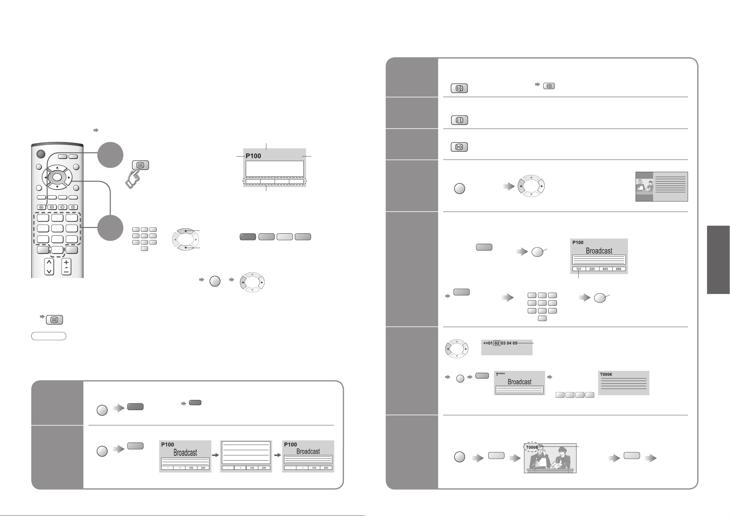
You can enjoy teletext broadcasting, including news, weather forecasts and subtitles, if this service is
provided by the broadcasters.
What is TOP / FLOF mode?
In TOP / FLOF mode, four differently coloured subjects are situated at the bottom of the display. To access more
information about one of these subjects, press the appropriately coloured button. This facility enables fast access to
information on the subjects shown.
What is List mode?
In List mode, four differently coloured page numbers are situated at the bottom of the screen. Each of these
numbers can be altered and stored in the TV’s memory. (
To change mode "Teletext" in Setup menu (p. 16)
■
"Store Frequently viewed pages", p. 13)
Sub page number
Switch to Teletext
1
Displays Index
•
(content varies
depending on the
broadcasters)
Current
page
number
Colour bar
Time / date
Select the page
up
down
or
(Corresponds to the colour bar)
As the blue bar is displayed
To return to TV
■
2
or
To adjust contrast
■
HOLD
INDEX
Call up a
favourite
pages
View in
multi
window
Store
frequently
viewed
pages
If you wish to hold the current page without updating
Stop or resume automatic updating
To resume
■
Return to the main index page
TOP / FLOF mode only
•
Call up the page stored in "blue".
•
Factory setting is "P103".
•
Watch TV and Teletext in two windows at once
(Press twice)
Operations can be made only in Teletext screen.
•
Select Picture and text
•
On or Off
Store frequently viewed pages
(only on first 25 Analogue channels on Programme
Guide) in the colour bar
As page is
displayed
To change stored pages
■
Colour button you
want to change
Corresponding
colour button
Enter new page number
hold
down
The number changes to white.
hold
down
(Analogue mode only)
(List mode only)
Any channels can
•
be stored in DVB
mode.
•
Viewing Teletext
Note
Contrast will be lowered
•
in the still picture to
prevent after-image.
Using teletext conveniently
■
Reveal
hidden
data
FULL /
TOP /
BOTTOM
Reveal hidden words e.g. quiz page answers
Re-hide
•
(TOP)
(BOTTOM)
(Expand the BOTTOM half)
Normal (FULL)
View sub
page
Watch
TV while
waiting
for update
View sub page (Only when teletext is more than one page)
Appears at upper-left
corner of the screen
To view specific sub page
■
Sub pages:
•
The number of sub pages varies depending on the broadcasters (up to 79 pages).
It may take some time for searching, during which time you can watch TV.
Enter the
4-digit number
example: P6
View theTV picture while searching for a teletext page
Teletext automatically updates itself when new information becomes available.
Changes to TV screen temporarily
Appears
when
updating is
completed
(You cannot change the channel.)
The news page provides a function that indicates arrival of latest news ("News Flash").
•
View the
updated
page
Page 8
14
15
Viewing
IDTV
REC
VCR DVD
TV/AV
PROGRAMME
OK
HDMI1/2
TV/AV
Watching Videos and DVDs
VCR DVD
PROGRAMME
REC
TV/AV
red
blue
yellow
blue
red
green
red
yellow
green
yellow
blue
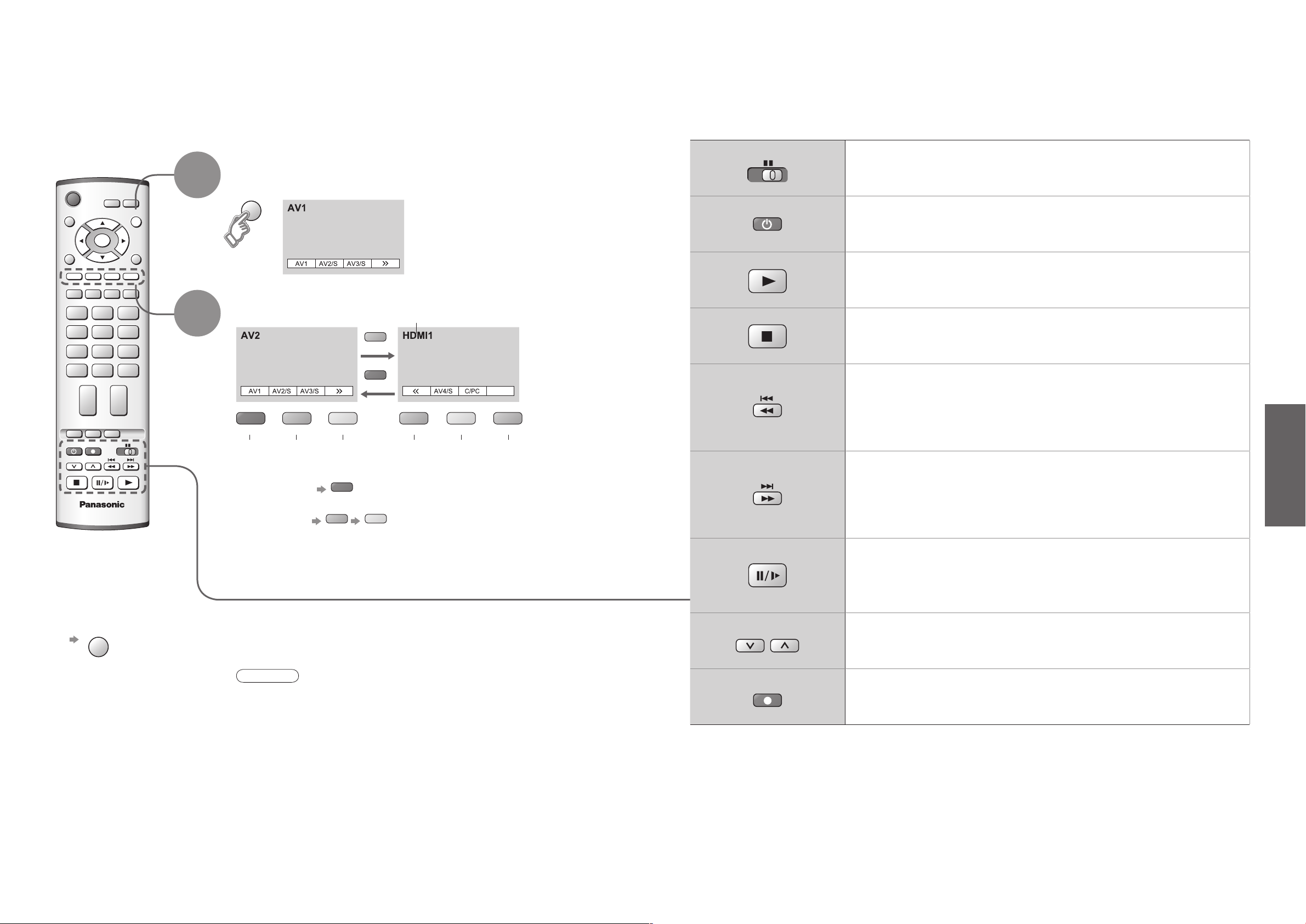
It is possible to connect a variety of external equipment to the TV unit. Once the equipment is connected,
use the following procedure to view the input.
To connect the equipment (p. 30)
With the equipment turned On
Select the external input
1
(AV mode screen)
Select the connector
2
connected to the equipment
AV1 AV2/
S-video
example: AV1
•
PC
AV3/
S-video
Displays the selected connector
AV4/
S-video
(twice)
Component/
PC
HDMI1/
HDMI2
Some Panasonic VCR and DVD equipment connected to the TV unit can be directly operated
with the remote control.
VCR / DVD switch
Select VCR / DVD
Standby
Set to Standby mode / Turn on
Play
Playback VCR / DVD
Stop
Stop the operations
Rewind / Skip / Search
VCR: Rewind, review (during playback)
DVD: Skip to the previous track or title
Press and hold to search backward
Fast-forward / Skip / Search
VCR: Fast-forward, cue (during playback)
DVD: Skip to the next track or title
Press and hold to search forward
•
Watching Videos and DVDs
To return to TV
■
Note
Automatic Input selection - Input mode is automatically switched from TV to AV
•
mode when the equipment connected via SCART or HDMI terminal is operated.
When the equipment is turned off, the TV is set to TV mode.
If the external equipment has an aspect adjustment function, set to "16:9".
•
For details, see the manual of the equipment or ask your local dealer.
•
Pause
Pause / Restart
DVD: Press and hold for slow-motion play
Programme Up / Down
Select programme
Record
Start recording
Page 9
Advanced
Ma i n men u
Pi c tu re m en u
So u nd me n u
Se t up me n
u
Viewing mode
Contrast
Brightness
Colour
Sharpness
Tint
Colour balance
Colour management
MPEG NR
Normal
On
Of
f
P-NR
Auto
Picture menu
Dynamic
3D-COMB On
IDTV
N
EXITMENU
OK
Viewing mode
Contrast
Brightness
Colour
Sharpness
Tint
Colour balance
Colour management
MPEG NR
Normal
On
Of
f
P-NR
Auto
3D-COMB O
n
Picture menu
Dynamic
Colour balance
Normal
Sharpness
Access
Tuning Menu
MENU
OK
16
17
How to Use Menu Functions
EXIT
MENU
N
Viewing mode Dynamic
Contrast
Brightness
Colour
Sharpness
Tint
Colour balance
Normal
Colour management On
P-NR
Auto
MPEG NR
Of
f
3D-COMB On
Bass
Treble
Balance
Headphone volume
MPX Stereo
Mode Music
Ambience Off
HDMI1 input Auto
Q-Link
AV2
AV2 out Monitor
Control with HDMI On
Teletext TOP
Off timer Off
Text language
West
Side panel Off
Power save Off
Programme edit
Access
Access
Auto setup
Manual tuning
Access
Fine tuning
Colour system
Auto
Volume correc.
Decoder (AV2)
Of
f
DVB Setup Menu
Access
System language
Access
Shipping condition
Access
Colour system
Auto
Volume correction
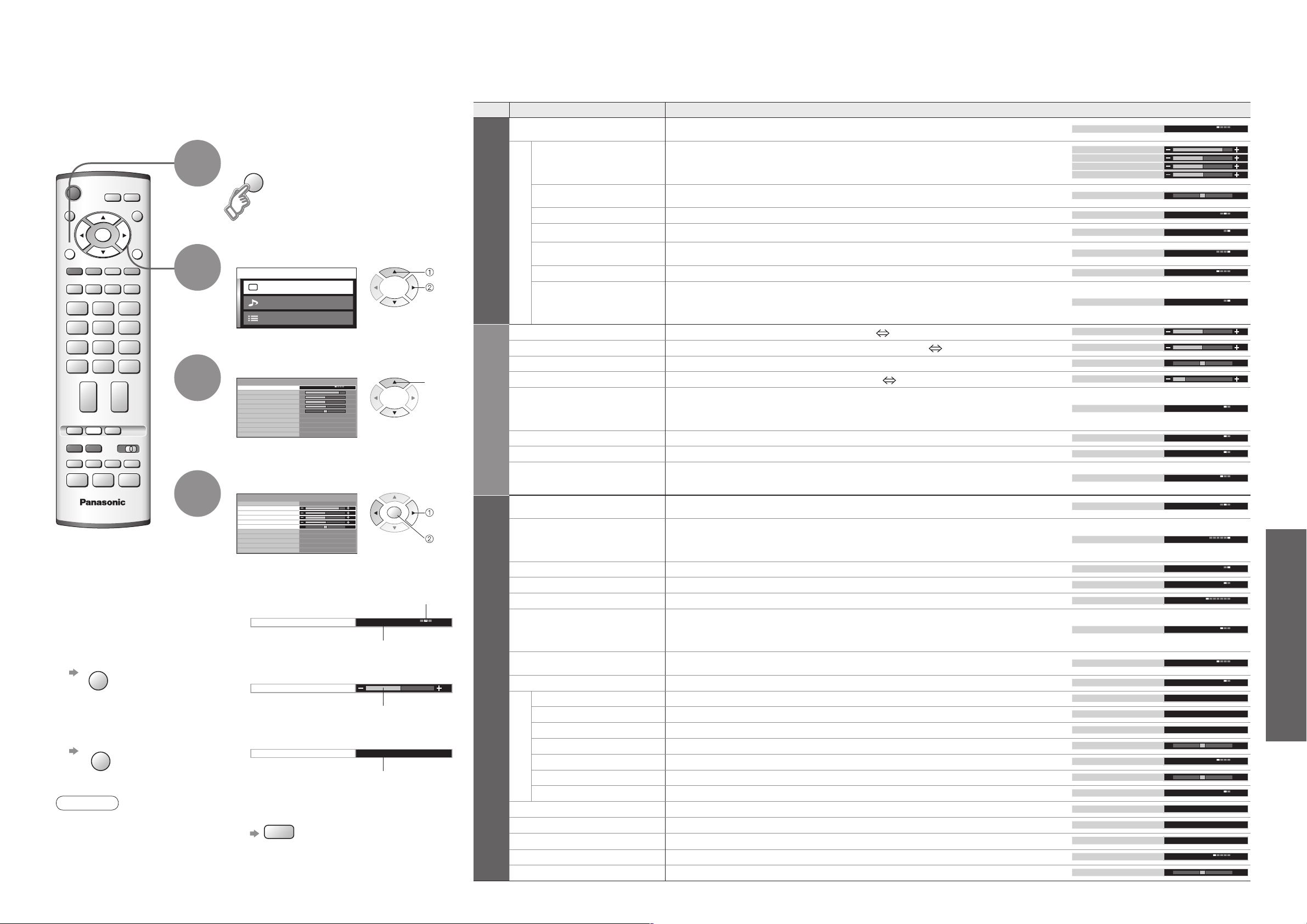
Various menus allow you to make settings for the picture, sound,
and other functions so that you can enjoy watching TV in your own way.
To return to TV
■
To return to the
■
previous screen
Note
To initialize all settings,
•
use "Shipping condition"
(p. 32).
1
2
3
4
Display menu
Displays the functions that
•
can be set (varies according
to the input signal)
Select the menu
(example: Picture menu)
Select the item
(example: Picture menu)
Adjust or select
(example: Picture menu)
Choose from among alternatives
■
Number and positions
of alternatives
Changed
Adjust using the slide bar
■
Moved
Go to the next screen
■
Displays the next
screen
To reset the setting
■
select
next
select
change
store
(Required
by some
functions)
Menu list
■
Menu Item Adjustments / Configurations (alternatives)
Viewing mode
Adjust by each viewing mode
Contrast,
Picture menu
Brightness, Colour,
Sharpness
Tint
Colour balance
Colour management
P-NR
MPEG NR
3D-COMB
Bass
Treble
Sound menu
Balance
Headphone volume
MPX
Mode
Ambience
HDMI1 input
Q-Link
AV2/AV3 out
Control with HDMI
Teletext
Off timer
Text language
Setup menu
Side panel
Power save
Programme edit
Tuning menu
Auto setup
Manual tuning
Fine tuning
Colour system
Volume correc.
Decoder (AV2 / AV3)
DVB Setup Menu
System language
Shipping condition
Colour system
Volume correction
Basic picture mode (Dynamic / Normal / Cinema / Auto)
Set for each input signal
•
Adjusts colour, brightness, etc. for each picture mode to suit your taste
Adjusts tint of image
For NTSC signal reception only
•
Chooses the colour balance of the entire image (Cool / Normal / Warm)
Automatically adjusts colours to vivid ones (Off / On)
Automatically reduces unwanted picture noise (Off / Normal / Dynamic / Auto)
Not valid on HDMI, PC, and HD signal
•
Automatically reduces noise for watching DTV, DVD and VCD (Off / Min / Mid / Max)
Automatically makes still pictures and slow pictures look more vivid (Off / On)
For PAL or NTSC signal reception only
•
Not valid on RGB, S-Video, components, PC and HDMI
•
Cannot be used with DVB
•
Adjusts the output level of deep bass (High Low)
Adjusts the output level of high-pitch, shrill sound (High Low)
Adjusts volume level of right and left speakers
Adjusts the volume of the headphones (High Low)
Select stereo / monaural (Mono / Stereo)
Normally: Stereo
•
Stereo signal cannot be received: Mono
•
M1 / M2: Available while mono signal is transmitted
•
Improves sound quality for music and dramas (Music / Speech)
Gives a greater spatial effect by using dynamic enhancer (Off / On)
Chooses according to the signal when HDMI is connected
(Auto / Digital / Analogue) (p. 34)
HDMI2 terminal is for digital signal only
•
Chooses the connector to which a Q-Link compatible equipment is connected
(Off / AV2 / AV3) (p. 30)
Chooses the signal to be transmitted from the TV to Q-Link
(Analogue / DVB / AV1 / AV2 / AV3 / AV4 / Monitor)
Monitor: Image displayed on screen
•
Component signals cannot be outputted
•
Control with HDMI function (Off / On) (p. 27)
Teletext display mode (TOP (FLOF) / List) (p. 12)
Sets the time the unit automatically turns Off. (Off / 15 / 30 / 45 / 60 / 75 / 90) (minutes)
Selects teletext language (West / East1 / East2)
West: English, French, German, Greek, Italian, Spanish, Swedish, Turkish
•
East1: Czech, English, Estonian, Lettish, Rumanian, Russian, Ukrainian
•
East2: Czech, Hungarian, Lettish, Polish, Rumanian
•
Increases the brightness of the side panel (Off / Low / Mid / High)
The recommended setting is High to prevent panel "after-image"
•
Reduces brightness of picture to economise on power consumption (Off / On)
Edits channels (p. 20)
Sets channels automatically (p. 20)
Sets channels manually (p. 20)
Fine tuning of channels (during rain, etc.)
Selects optional colour system depending on video signals
Adjusts volume of individual stations
Set “On” when the decoder is connected to AV2 or AV3 terminal via a Q-Link equipment
Edits or setups DVB channels (p. 18)
Changes language for on-screen displays
Resets all settings, for example, when moving (p. 32)
Selects optional colour system based on video signals in AV mode
Adjusts volume for AV, PC, and HDMI mode
A different menu will be displayed while PC is used. (p. 25)
•
In AV mode, the Sound menu and Setup menu give a smaller number of options.
•
Cannot be used with DVB
•
(Auto / PAL / SECAM / M.NTSC)
(Off / On)
•
How to Use Menu Functions
(picture, sound quality, etc.)
Page 10
Advanced
Ma in me nu
Pi ct ure m enu
So un d m en
u
Se tu p m en
u
Control with HDMI
Setup menu
AV2
Q-Link
TO
P
On
AV
2 out
Monitor
Off
Off
Off
Off timer
Side panel
Power save
System language
Access
DVB Setup Menu
Shipping condition
Te
letext
Child Lock
Profile Edit
Tu
ner Lock
DVB Setup Menu
System Setup
System Update
Access
Access
Teletext
Subtitles
Tu
ning Menu
Off
ger
ger
Multi Audio ger
IDTV
EXITMENU
OK
MENU
OK
18
19
Advanced DVB Settings
EXIT
Auto
3 seconds
Common Interface Module
Ti
me Zone
DVB System Setup
Access
Display Timeout
Preferred Language Setting
OK
red
green
yellow
blue
Auto
3 seconds
Common Interface Module
Time Zone
DVB System Setup
Display Timeout
Preferred Language Setting
3 seconds
Auto
Common Interface Module
Time Zone
DVB System Setup
Display Timeout
Preferred Language Setting
Auto Update Search in Standby
Software Licence
DVB System Update
On
System Update Search Now
Access
3 seconds
Auto
Common Interface Module
Time Zone
DVB System Setup
Display Timeout
Preferred Language Setting
(DVB mode only)
1
2
3
Display the menu
Select "Setup menu"
Select "DVB Setup Menu"
next
select
next
select
Pay-TV
Common
Interface
Module
Language
of subtitles
Preferred
Language
Setting
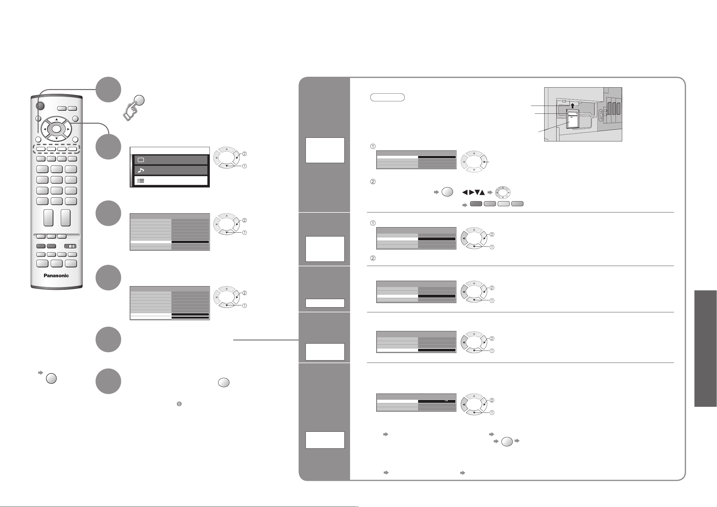
Insert the CI module (optional)
Caution
Turn Off the On / Off switch on the TV unit
•
whenever inserting or removing the CI module.
If a view card and a card reader come as a set,
•
first insert the card reader, then insert the view
card into the card reader.
Select "Common Interface Module"
next
Follow the on-screen instructions
example:
select, go
Coloured characters
Select "Preferred Language Setting"
next
select
Set the language (Audio, Subtitles, Teletext)
CI slot
Insert or
remove
squarely
CI module
(Rear of the TV)
For more details, see the manual of the CI
•
module, or check with the broadcaster.
Normally pay-TV services will appear without
•
following steps 1 and 2 (shown for information only).
On-screen operation guide may not correspond
•
to the remote control buttons.
This is the initial language setting for Audio,
•
Subtitles (p. 11) and Teletext.
•
Advanced DVB Settings (DVB)
(pay-TV, time, etc.)
To exit
■
4
Select "System Setup" or
"System Update"
next
select
Adjust the
time data
automatically
Time Zone
Select "Time Zone" and set the time
set
select
Auto : The time data will be adjusted according to
your area automatically.
Others : The time data will be corrected based on
GMT.
Information
banner
display time
5
6
Select a function and set
Store
If you exit after , the setting is not stored after
•
turning off the unit.
Display
Timeout
Update
unit's
software
system
System
Update
Select "Display Timeout" and set the time
set
select
Update the software at appropriate intervals to ensure that the unit's performance and functions are updated.
For details (p. 32)
0 (none displayed) to 10 sec. in 1-sec.
•
increments
Information banner (p. 10)
•
Select "Auto Update Search in Standby" and then select "On" or "Off"
set
select
To update immediately
■
Select "System Update Search Now" Searches for an update (for several min.) and
displays a corresponding message if any OK Downloads (for about 20 min.)
The message might be the notification beforehand. In this case, the schedule information (the date that the
•
new version can be used) will appear.
View software licence information
■
Select "Software Licence" Display
On: Automatically performs a search in standby
•
at 3:00 AM and 5:00 AM and downloads an
update, if any
Page 11
Advanced
Ma in me nu
Pi ct ure m enu
So un d m en
u
Se tu p m en
u
Q-Link
Control with HDMI
Off timer
System language
Shipping condition
Setup menu
Off
Text language
West
Side panel
Off
Power save
Off
Tuning menu
Access
Teletext
TOP
On
AV2 out
Monitor
AV
2
Programme edit
Auto setup
Manual tuning
Colour system
Fine tuning
Vo
lume correc.
Decoder (AV2)
Tuning menu
Access
Off
Auto
IDTV
EXITMENU
OK
AV4
MENU
20
21
Editing and Setting Channels
EXIT
Manual tuning
02 78:01 41
CH12
1
Exit
Search down/up
Return
Direct entry
Store
C
0
9
OK
Programme edit
Prog. Chan. Name Lock Sys
1 :
2
:
3 :
4
:
5
:
CH44
CH51
CH41
CH47
CH37
Off
Off
Off
Off
Of
f
SC1
SC1
SC1
SC1
SC1
ABC
XYZ
FTP
123
456
Programme edit
Prog. Chan. Name Lock Sys
1
:
2
:
3
:
4 :
5
:
CH44
CH51
CH41
CH47
CH37
ABC
XYZ
FTP
123
456
Of
f
Of
f
Of
f
Off
Of
f
SC1
SC1
SC1
SC1
SC1
Programme edit
Prog. Chan. Name Lock Sys
1 :
2 :
3 :
4 :
5 :
CH44
CH51
CH41
CH47
CH37
ABC
XYZ
FTP
123
456
Off
Off
Off
Off
Off
SC1
SC1
SC1
SC1
SC1
ABCDEFGHIJKLMNOPQRST
UVWXYZ+-. 0123456789
Programme edit
Prog. Chan. Name Lock Sys
1 :
2 :
3 :
4 :
5 :
CH44
CH51
CH41
CH47
CH37
Off
Off
Off
Off
Off
SC1
SC1
SC1
SC1
SC1
XYZ
FT
P
123
456
OK
blue
red
red
green
green
yellow
yellow
All analogue tuning
data will be erased
WARNIN G
Exit
Return
Start Auto Setup
OK
AUTO SETUP IN PROGRESS
SEARCHING : PLEASE WAIT
02 78:01 41
CH12
Exit
Return
STR F- / + / TV / AV
SC1
CH12
1
Manual tuning
02 78:01 41
-
, + : Search
TV / AV
: Move cursor
STR : To store
F : To exit
Programme edit
Prog. Chan. Name Lock Sys
1 :
2 :
3 :
4 :
5 :
CH44
CH51
CH41
CH47
CH37
ABC
XYZ
FTP
123
456
Off
Off
Off
Off
Off
SC1
SC1
SC1
SC1
SC1
(Analogue mode)
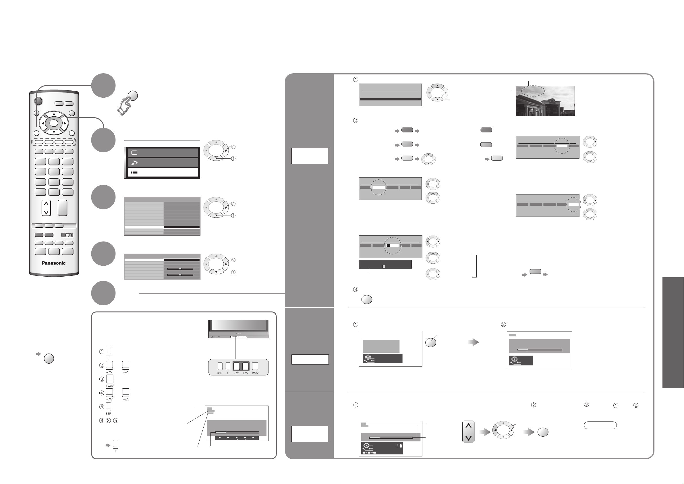
The current channel settings can be changed according to your needs and reception conditions.
1
2
3
4
5
Display the menu
Select "Setup menu"
Select "Tuning menu"
Select the function
Set
next
select
next
select
next
select
Edit
channels
Programme
edit
Delete
■
Add
■
Move
■
Change
■
channel
number
Change
■
name
Lock
■
Change
■
sound
system
Download to
■
equipment
Select the programme number to edit
select
Cursor
Edit
To delete
■
To add
■
To move
■
To change channel number
■
To change the name of the broadcaster
■
After confirming, press
After confirming, press
Select destination
Select the
"Chan." field
Change number
(Can also be changed
with "C" and number
buttons)
displayed when selecting channels
Select the
"Name" field
Select the
character
Usable characters
To next
character
Store
Programme
number
Repeat
Name
3 FTP
To lock
■
Select the "Lock"
field
Select "On"
("Off" to unlock)
You cannot select the channel with number
•
buttons or the "C" button when locked.
To change sound system based on signals
■
Select the "Sys" field
Select sound system
SC1 : PAL B, G, H / SECAM B, G
SC2 : PAL I
SC3 : PAL D, K / SECAM D, K
F : SECAM L / L’
To download channel information to a Q-Link
■
compatible equipment connected to the unit
Automatically transmitted
(for a few sec.)
For details (p. 26)
•
Not available if "Q-Link" is "Off" in the Setup
•
menu. (p. 16)
•
Editing and Setting Channels
(Analogue)
To exit
■
No data is stored
•
if an Auto setup
sequence is
interrupted.
Automatically set the channels received in the area
For Manual tuning, using
the buttons on the unit
("Tuning mode" on p. 7)
Set
automatically
(Press repeatedly until "Tuning mode" appears)
Auto setup
or (Access "Manual tuning")
(Programme, Channel (select), Sound system)
or (Change programme or start searching channels)
(Store)
-
(Repeat)
To return to TV
■
Programme
number (flash)
Channel
number
(flash)
Sound system
(flash)
Channel
Set
manually
Manual
tuning
Start Auto setup
Settings are made automatically
set
The settings are downloaded to a Q-Link compatible equipment connected to the unit.
•
All previous settings are erased.
•
When the sequence is completed, the broadcast of programme number "1" will appear.
•
To freely change settings after Auto setup
Select the programme number
Store
and search through the channel
Programme
number
Channel
search
The programme
•
number blinks.
Repeat and
Note
If a VCR is connected
•
with only the RF cable,
select programme
number "0".
Page 12
Advanced
Ma in me nu
Pi ct ure m enu
So un d m en
u
Se tu p m en
u
Control with HDMI
Setup menu
AV2
Q-Link
TO
P
On
AV
2 out
Monitor
Off
Off
Off
Off timer
Side panel
Power save
System language
Access
DVB Setup Menu
Shipping condition
Te
letext
Profile Edit
Multi Audio
DVB Setup Menu
System Setup
System Update
Access
Teletext
Subtitles
Child Lock
ger
ger
ger
Tuning Menu
Tuner Lock
Access
Off
IDTV
VCR
EXIT
1 2 3
4 5
6
7 8
9
0
MENU
OK
Pr ofi le Ed ito r
1 Da s E rst e
2 ar te
3 PH OEN IX
4 AR D-M HP- Dat a
Al l S erv ic es Pro fil e 1
Pr ofi le Ed ito r
1 Da s E rst e
2 ar te
3 PH OEN IX
4 AR D-M HP- Dat a
1 ar te
2 AR D-M HP- Dat a
Al l S erv ic es Pro fil e 1
* * * *
Please enter new PIN
Child Lock-PIN Entry
PIN
Change PIN
Child Lock
Child Lock Service List
Access
Ch ild Lo ck Se rvi ce Lis t
1 Da s E rs te
2 ar te
3 PH OEN IX
4 AR D-M HP -Da ta
5 ZD F
6 In fo/ 3s at
7 Do ku/ Ki Ka
MENU
VCR
1 2 3
4 5
6
7 8
9
0
OK
OK
22
23
Editing and Setting Channels
EXIT
red
green
green
OK
yellow
blue
blue
green
OK
yellow
blue
yellow
(DVB mode)
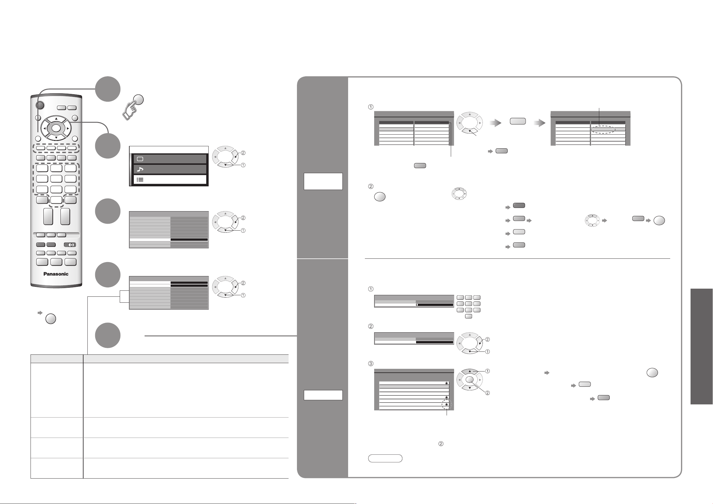
Your favourite channels can be listed, and children can be prevented from watching specific channels.
Display the menu
Create your favourite channel list (Profile) from various broadcasters (up to 4: Profile 1 to 4).
1
The list is displayed in information banner (p. 10) and then easily accessed.
Select a broadcaster and add it to the list
A broadcaster is added
To exit
■
Select "Setup menu"
2
next
select
List
favourite
channels
To display
another Profile
Profile
Edit
Store
Select "DVB Setup Menu"
3
Select the function
4
next
select
next or set
select
You can lock specific broadcasters so that children cannot watch them.
(When a channel is selected, a message appears; by entering the PIN number, you can watch the channel.)
Enter the PIN number (4 digits)
•
To edit Profile
■
Name the Profile
•
Move the station
•
Delete the station
•
Delete all stations
•
select
To add all stations
to the list
Move the cursor to the field of Profile to edit and:
Select the position Confirm
Enter the PIN number twice at first setting.
•
Make a note of the PIN number in case you forget it.
•
•
Editing and Setting Channels
(DVB)
5
Set
Item Adjustments / Configurations
Prevents you from accidentally changing programme while recording a DVB
broadcaster. If the TV is turned to Standby mode while Tuner Lock is On, the DVB
tuner will remain active to ensure recording can still take place.
Tuner Lock
Multi Audio
Subtitles
Teletext
Use for the recording without watching DVB broadcaster.
•
Do not switch the TV unit Off during recording.
•
Even if the TV unit is switched On or Off, this setting is memorized.
•
While recording a DVB programme, it is possible to change to the Analogue
•
programmes to watch.
Selects from several sound tracks (varies depending on the broadcaster).
This setting is available only for the present broadcaster.
•
Selects the language for subtitles (varies depending on the broadcaster).
This setting is available only for the present broadcaster.
•
Selects the language for teletext mode (varies depending on the broadcaster).
This setting is available only for the present broadcaster.
•
Prevent
children
from
watching
specific
channels
Child Lock
Select "Child Lock Service List"
Select the station to be locked
To change the PIN number
■
Select "Change PIN" in and enter a new PIN number twice.
Note
Setting "Shipping condition" (p. 32) erases the PIN number and all settings.
•
Appears when the
station is locked
next
select
select
set
To cancel Select the locked station and press
•
To lock all channels
•
To cancel all channel locks
•
Page 13
Advanced
Ma in me nu
Pi ct ure m enu
So un d m en
u
Se tu p m en
u
Child Lock
Profile Edit
Tu
ner Lock
DVB Setup Menu
System Setup
System Update
Access
Teletext
Subtitles
Tu
ning Menu
Off
ger
ger
Multi Audio ger
EXITMENU
OK
Auto Setup
New Service Message
DVB Tuning Menu
Access
On
Signal Condition
Manual Tuning
Add New Service
New D VB Se rvi ce Fo und !
Pre ss OK t o a dd ne w s ervic e
Pre ss EX IT to lgno re
DVB Programme
0 5 10
CH30 1 BBC ONE Wales
Signal Strength
Signal Quality
TV/AV
OK
MENU
TV/AV
24
25
Editing and Setting Channels
EXIT
TV/AV
blue
yellow
Displaying PC Screen on TV
(DVB mode)
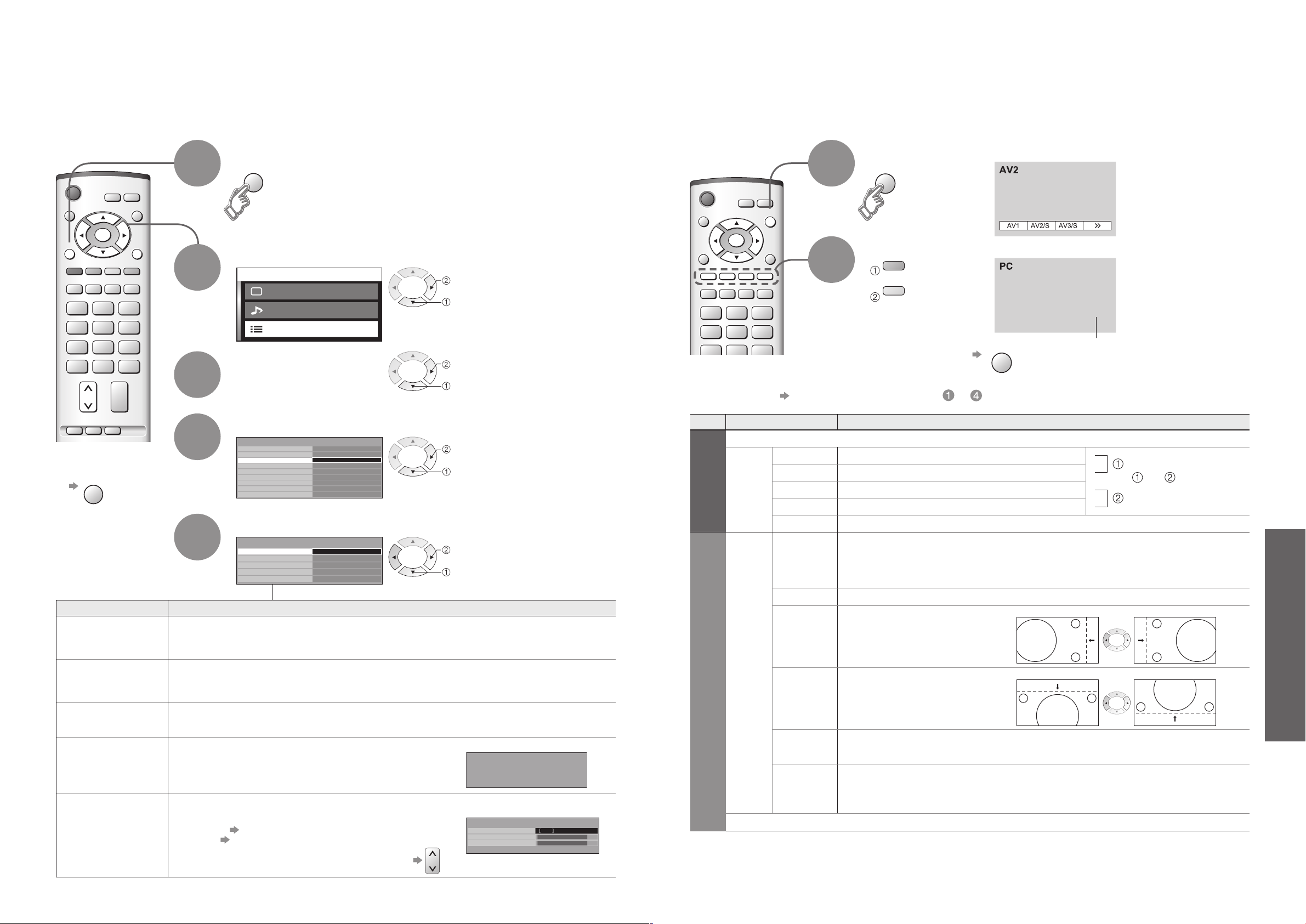
You can re-tune all TV channels when moving house or search for new services which may have
recently started broadcasting.
To exit
■
•
Auto Setup
Add New Service
Manual Tuning
New Service
Message
Signal Condition
Display the menu
1
Select "Setup menu"
2
Select
3
"DVB Setup Menu"
Select "Tuning Menu"
4
No data is stored
if an Auto Setup
sequence is
interrupted.
Item Adjustments / Configurations
5
Automatically sets the DVB channels in the area.
The current setting is erased.
•
If a Child Lock PIN number (p. 22) has been set, it must be entered again.
•
Adds a new DVB station.
A new station is added to the DVB channel list, when found.
•
The new station is added with the current settings saved as they are.
•
Sets the DVB channels manually.
Normally use "Auto Setup" or "Add New Service" for the channel setting.
Selects whether to give a notification message
when a new DVB station is found.
(On / Off)
Selects a channel and checks the DVB signal condition.
Use for adjusting the direction of the aerial.
Green bar Good
•
Red bar Poor (Check the aerial)
•
To change the programme during the menu appears
•
Select the function and set
next
select
next
select
next
select
set
select
(Message example)
The screen of the PC connected to the unit can be displayed on the TV.
You can also listen to PC sound with the audio cable connected. To connect PC (p. 30)
Select the external input
1
Select "PC"
2
■
PC menu setting (changed as desired)
■
Making settings "How to Use Menu Functions" to (p. 16)
•
Menu Item Adjustments / Configurations(options)
Picture menu
Viewing mode, Contrast, Brightness, Sharpness, Colour balance (p. 16)
W/B High R White balance of bright red area
W/B High B White balance of bright blue area
Advanced
setting
Setup menu
PC
setup
Volume correction, Side panel, Power save, System language (p. 16)
Sound menu (p. 16)
•
W/B Low R White balance of dark red area
W/B Low B White balance of dark blue area
Gamma (2.0 / 2.2 / 2.5 / S Curve)
Input
resolution
Clock Set to the minimum level if noise occurs
H-pos
V-pos
Clock phase
Sync
Switches to a wide view
VGA (640 x 480 dots), WVGA (852 x 480 dots),
•
XGA (1,024 x 768 dots), WXGA (1,366 x 768 dots)
Options change depending on signals
•
Adjust horizontal position
Adjust vertical position
Eliminate flicker and distortion
Adjust after Clock adjustment
•
Chooses another synchronous signal if the image is distorted (H&V / On G)
H&V : by the horizontal and vertical signals from your PC
•
On G : by the green signal from your PC (if available)
(To next page)
Press twice
To return to TV
Displays PC screen
Set to the minimum level if noise occurs
•
Corresponding signals
•
(p. 35)
If "H-freq." or "V-freq."
•
is shown in red, the
signals may not be
supported.
and
repeatedly adjusted
•
Editing and Setting Channels (DVB)
•
Displaying PC Screen on TV
Page 14
Advanced
Control with HDMI
Setup menu
AV2
Q-Lin
k
TO
P
On
AV2 ou
t
Monitor
Of
f
Of
f
Side pane
l
Power save
System language
Tuning menu
Shipping condition
Teletex
t
Text language
West
Off time
r
Of
f
IDTV
MENU
OK
MENU
26
27
External Equipment
Ma in me nu
Pi ct ure m enu
So un d m en
u
Se tu p m en u
Ho me th ea tre
EXIT
DIRECT
TV REC
EXIT
DIRECT
TV REC
Mai n m e nu
Pic t u r e m e nu
Sou n d m en
u
Set u p m en u
Hom e t h ea t re
MENU
Q-Link
Q-Link interlocks the TV unit and VCR / DVD recorder, enables easy recording and playback.
Condition
■
Use the VCR / DVD recorder with the following logos:
•
"Q-Link", "NEXTVIEWLINK", "DATA LOGIC", "Easy Link", "Megalogic", or "SMARTLINK"
Connect the equipment to this unit’s AV2 or AV3 terminal via a "fully-wired" SCART cable. (p. 28)
•
Q-Link terminal setup in Setup menu (Q-Link, AV2/AV3 out). (p. 16)
•
Download analogue channel settings
■
Perform Auto setup. (p. 20)
•
When first using this unit, see "Auto Setup". (p. 9)
Perform download to the equipment. (p. 20)
•
Features available
■
Some recording equipments are not applicable. Read the manuals of the equipment.
Direct TV Recording:
Recording the current programme in VCR / DVD recorder immediately.
When Direct TV Recording is performed, the
•
recording equipment is automatically turned on if it
is in Standby mode.
The recording equipment is recording from its own
What you
see is
What you
record
■
•
tuner. You can turn the TV off during recording
(Analogue only).
Do not turn the TV off during recording AV source.
•
Otherwise the recording will be stopped.
When Direct TV Recording is performed while
•
watching DVB channel, the DVB programme
position is locked and no other DVB channel can
be selected. (but not for the Analogue channel.)
To change DVB channel, stop recording
Control with HDMI " Control"
∗
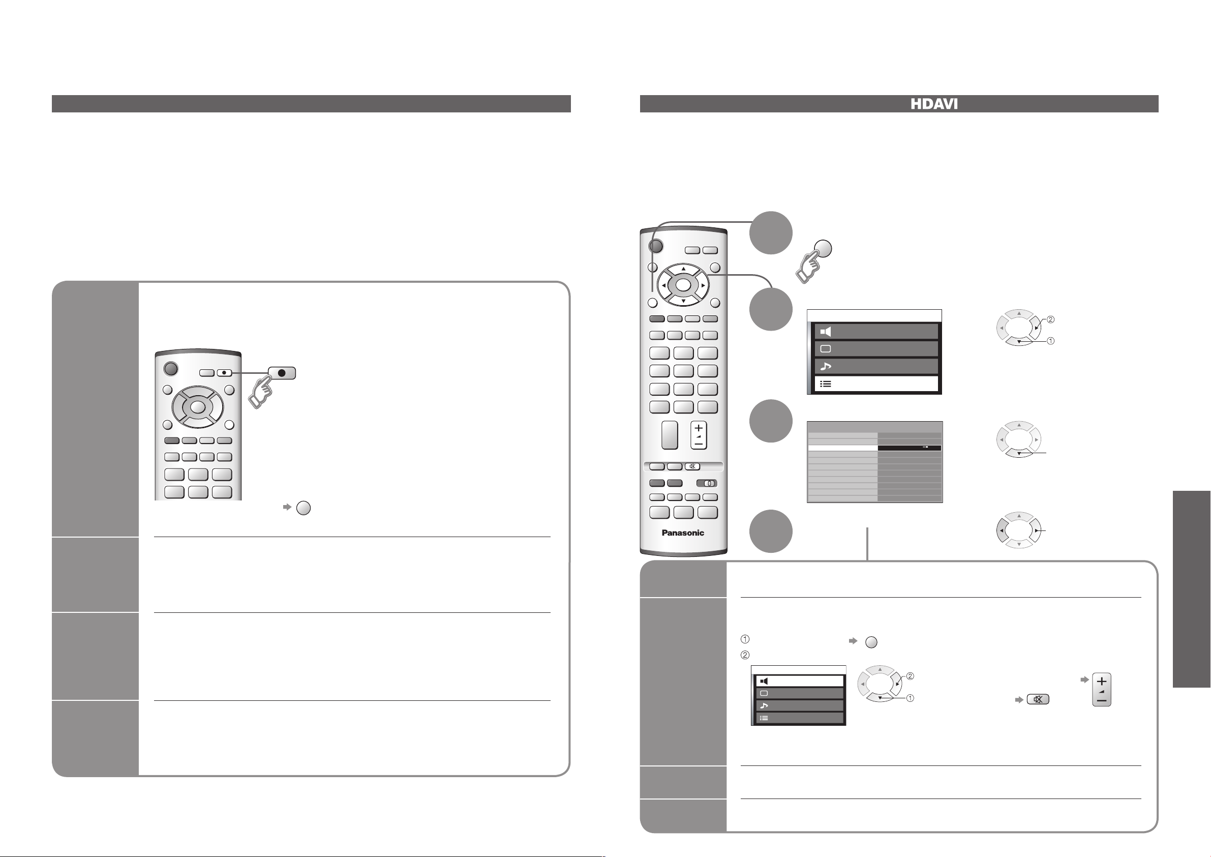
Enjoy additional HDMI Inter-Operability with Panasonic products which have "HDAVI Control" function.
HDMI connections to some Panasonic equipments (Panasonic DVD Recorder DIGA, Panasonic Player
theatre, Panasonic Amplifier, etc.) allow you to enjoy the easy playback or home theatre.
About connections, see "Connections" (p. 29). Read the manuals of the equipment too.
Non-HDMI-compliant cables cannot be utilized.
About applicable equipments, consult your local Panasonic dealer.
∗
After connections turn the equipments on and then, switch the TV unit on.
Display the menu
1
Select "Setup menu"
2
next
select
Select "Control with HDMI"
3
select
•
External Equipment
Information
/ Message
Recording information or if recording is not possible, a message is displayed.
(Only when the programme number is "0" or "AV mode" for some equipment.)
Power
on link
and Easy
Insert a videocassette or DVD in the recording equipment and it is operated, TV
is turned on and input mode is switched automatically so that you can view the
content. (Only when TV is in Standby mode.)
playback
Power off
link
• "DATA LOGIC" (a trademark of Metz Corporation) • "Megalogic" (a trademark of Grundig Corporation)
• "Easy Link" (a trademark of Philips Corporation) • "SMARTLINK" (a trademark of Sony Corporation)
Read the manuals of the equipment too.
When TV is set to Standby mode, the recording equipment is also automatically
set to Standby. (Only when the videocassette or DVD is not active.)
Easy
playback
Theatre
speaker
Power on
link
Power off
link
Select "On" (default is On)
select
4
Automatic Input switching-When the connected Panasonic equipment is operated, input
mode is switched automatically. When it is stopped operating, input mode is returned.
You can control the theatre speaker with TV’s remote control.
This function is available when Panasonic Amplifier or Player theatre is connected.
Home theatre:
Display the menu
Select "Home theatre" or "TV speaker"
next
select
When selecting "Home theatre", the sound of TV speakers is mute.
•
When the equipment is turned off, TV speakers will be active.
•
When the connected Panasonic equipment is operated, TV is also automatically
turned on and the content is reproduced. (Only when TV is in Standby mode.)
When TV is set to Standby mode, the connected Panasonic equipment is also
automatically set to Standby.
■
Adjustment for equipment (automatically
turned on if it is in Standby mode)
Volume up / down
Mute
TV speaker:
■
TV speakers are active.
Page 15
Advanced
1
2
AV
AV 1 AV 2 AV 3
PC
AUDIO RGB VIDEO VIDEO VIDEO AUDIO
RG
B
VIDEO S-VIDEO S-VIDE
O
COMPONENT
AUDIO
IN
L
R
L
R
Y
P
B
PR
1
2
AV
AV
1 AV 2 AV 3
PC
AUDIO RGB VIDEO VIDEO VIDEO AUDIO
RG
B
VIDEO S-VIDEO S-VIDE
O
COMPONENT
AUDIO
IN
L
R
L
R
Y
P
B
P
R
AV4
S-V V L R
1
2
AV
AV 1 AV 2 AV 3
PC
AUDIO RGB VIDEO VIDEO VIDEO AUDIO
RG
B
VIDEO S-VIDEO S-VIDE
O
COMPONENT
AUDIO
IN
L
R
L
R
Y
P
B
P
R
AV4
S-V V L R
L
R
P
R
P
B
Y
R
L
V
S-V
R
L
V
S-V
1
2
AV
AV 1 AV 2 AV 3
PC
AUDIO RGB VIDEO VIDEO VIDEO AUDIO
RG
B
VIDEO S-VIDEO S-VIDE
O
COMPONENT
AUDIO
IN
L
R
L
R
Y
P
B
P
R
1
2
AV
AV
1 AV 2 AV 3
PC
AUDIO RGB VIDEO VIDEO VIDEO AUDIO
RG
B
VIDEO S-VIDEO S-VIDE
O
COMPONENT
AUDIO
IN
L
R
L
R
Y
P
B
PR
1
2
AV
AV 1 AV 2 AV 3
PC
AUDIO RGB VIDEO VIDEO VIDEO AUDIO
RG
B
VIDEO S-VIDEO S-VIDE
O
COMPONENT
AUDIO
IN
L
R
L
R
Y
P
B
PR
28
29
External Equipment
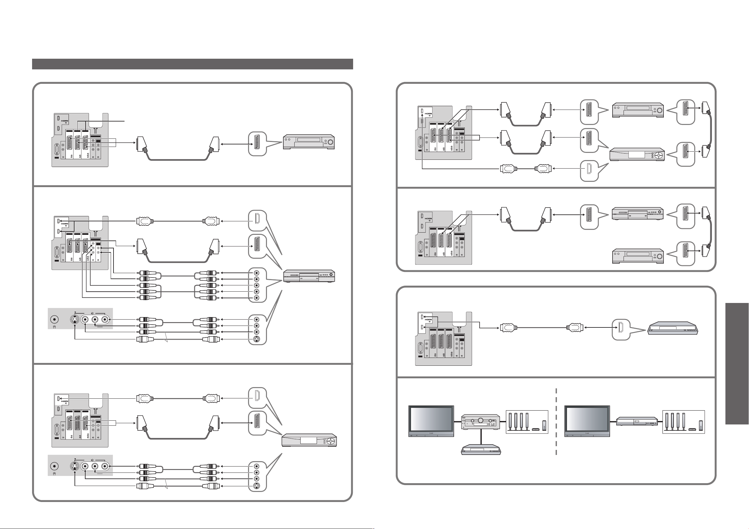
Connections
External equipments and cables shown are not supplied with this TV.
•
Connect VCR / DVD recorder (Recording, Playback)
■
Rear of the TV
Connect DVD player (Playback)
■
Rear of the TV
Front of the TV
Connect VCR / DVD recorder and Set top box (example)
■
VCR / DVD recorder
For Q-Link connection (p. 26)
Rear of the TV
SCART SCART
VCR / DVD recorder
SCART
or
Connect DVD recorder and VCR (example)
■
SCART
HDMI
Rear of the TV
Set top box
SCART
DVD recorder
•
DIGA
SCART
SCART
External Equipment
HDMI
SCART
or
VCR
or
or
SCART
DVD player
Control with HDMI (p. 27)
Easy playback (For connection to HDMI2 terminal, refer to p. 30)
■
Rear of the TV
Panasonic DVD recorder
Connect Set top box (RGB input)
■
Rear of the TV
Front of the TV
Connect the S-VIDEO or VIDEO terminal.
HDMI
Home theatre
■
This TV
Panasonic
Amplifier
Speaker system
This TV
or
or
SCART
Set top box
Panasonic DVD recorder
HDMI
Panasonic
Player theatre
Speaker system
DIGA
Connect the S-VIDEO or VIDEO terminal.
Read the manuals of Panasonic Amplifier or Player theatre for details.
It is recommended that you use Panasonic’s HDMI cable.
•
Recommended part number: RP-CDHG15 (1.5 m)
RP-CDHG30 (3.0 m)
RP-CDHG50 (5.0 m)
Page 16
Advanced
30
31
1
2
AV
AV
1 AV 2 AV 3
PC
AUDIO RGB VIDEO VIDEO VIDEO AUDIO
RGB
VIDEO S-VIDEO S-VIDEO
COMPONENT
AUDIO
IN
L
R
L
R
Y
PB
P
R
AV4
S-V V L R
Y
PB
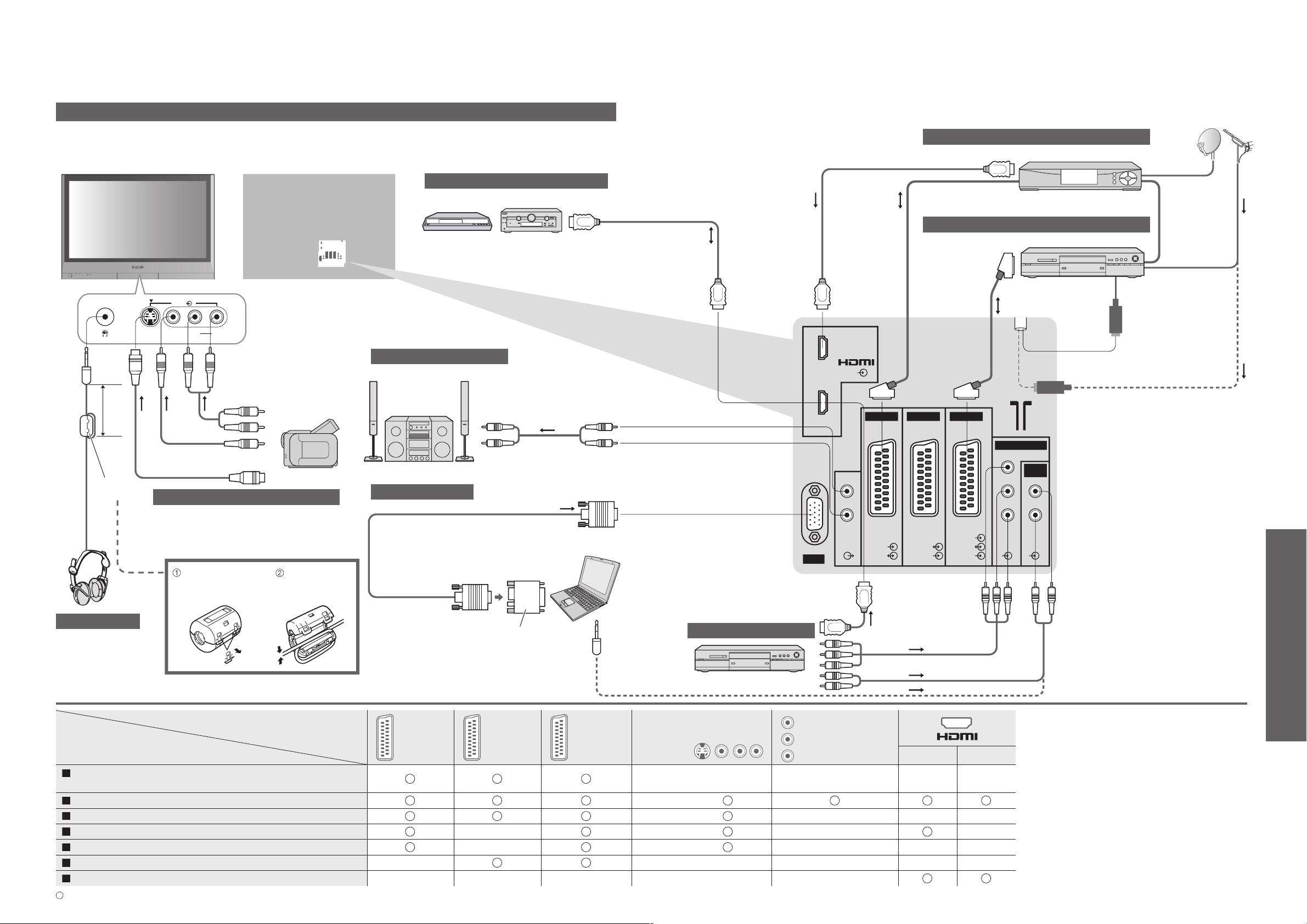
PR
External Equipment
Connections (overview)
These diagrams show our recommendations for how to connect the TV unit to your various equipment.
For other connections, consult the instructions of each equipment, the table below, and the specifications
(p. 39).
Control with HDMI (p. 27)
DIGA or Panasonic Amplifier
When using HDMI2 terminal as Control
•
with HDMI, select the external input to
HDMI2 for the first time (p. 14).
To listen with speakers
(M3
plug)
within
10 cm
Ferrite
core
(AUDIO)
(VIDEO)
or
(S-VIDEO)
Camcorder / Game equipment
Amplifier with speaker system
PC
(Viewing)
SCART
cable
To watch satellite broadcasts
Set top box
To record / playback
DVD Recorder / VCR
SCART
cable
(Q-Link)
(Q-Link)
SCART
cable
RF cable
or
•
External Equipment
Pull back the
tabs to open
Press the
cable through
and close
Headphones
Types of connectable equipment to each connector
Connector
Recording / Playback (equipment)
To record / playback videocassettes / DVDs
(VCR / DVD recorder)
To watch DVDs (DVD player)
To watch camcorder images (Video camera)
To watch satellite broadcasts (Set top box)
To play games (Game equipment)
Q-Link
Control with HDMI
: Recommended Connection
Computer
Conversion adapter (if necessary)
(Listening)
AV1 AV2 AV3
To watch DVDs
DVD player
AV4
COMPONENT
1 2
Page 17
FAQs, etc.
Ma i n m en u
Pi c tu r e m en u
So u nd me n
u
Se t up me n
u
Control with HDMI
Setup menu
AV2
Q-Link
TO
P
On
AV
2 out
Monitor
Off
Off
West
Off timer
Te
xt language
Side panel
System language
Access
Tuning menu
Off
Power save
Shipping condition
Te
letext
Deutschland
France
Land
All tuning data will be erased
Shipping condition
Exit
Return
Start
MENU
OK
OK
32
33
Technical Information
14 : 9
16 : 9
Zoom3
Zoom2
Just
4 : 3
Zoom1
4 : 3 Full
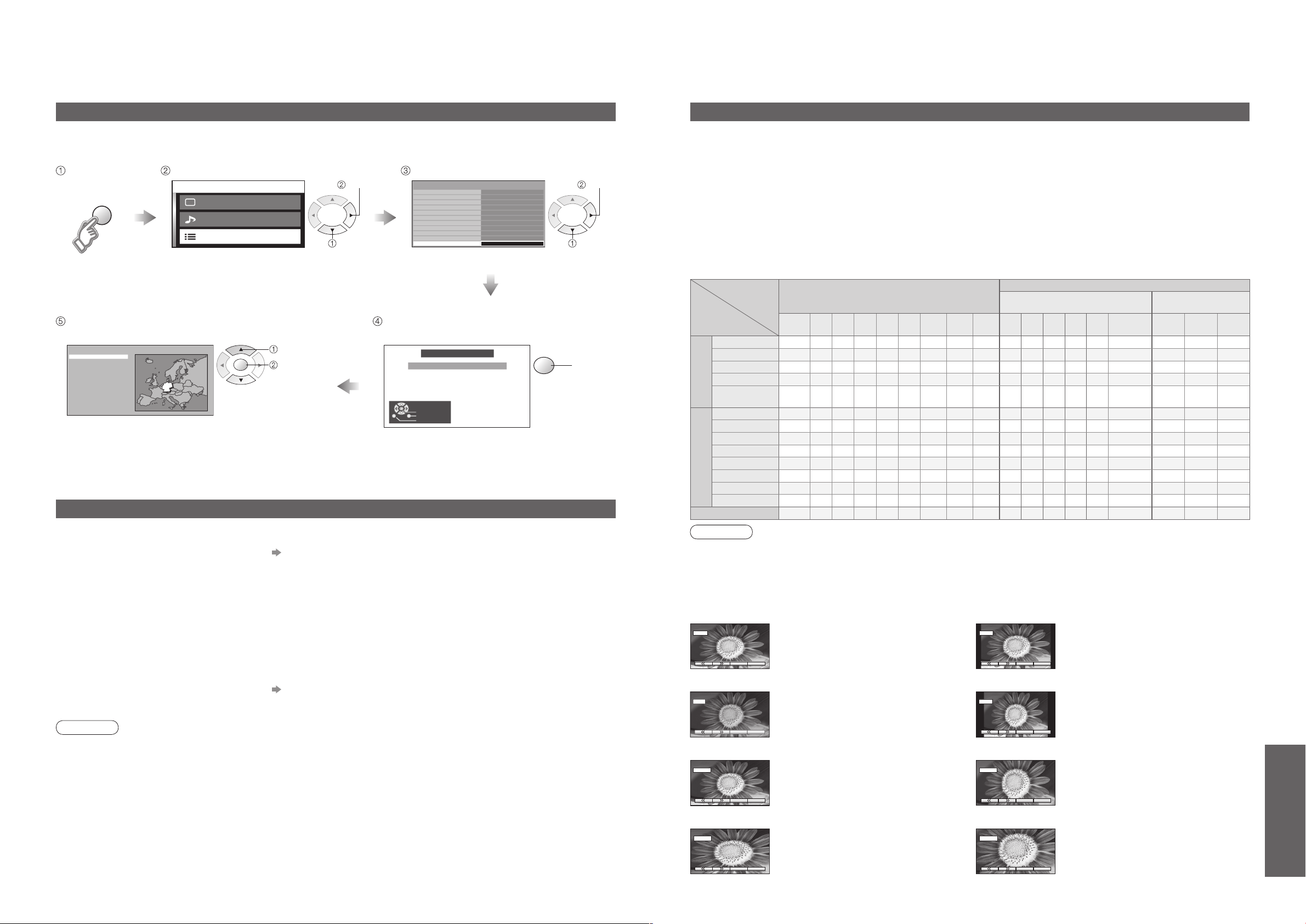
Shipping condition (Restore settings)
Shipping condition will reset all settings, even if Child Lock PIN number (p. 22), clearing all DVB and Analogue
tuning data and resetting all control levels back to factory settings.
Display
the menu
Select your country and
start Auto Setup
"Auto Setup" will automatically start. (p. 9)
•
Select "Setup menu" Select "Shipping condition"
next
select
Check the message and follow the
on-screen instructions
select
start
select
set
Updating the software system (DVB mode)
Update system software regularly to ensure that you have latest version software.
If there is an update available, a notification banner is displayed when the channel has the update information.
To download new software, press "OK" Downloading (approx. 20 min.)
•
If you choose not to download, press "EXIT".
To update automatically
■
Set "Auto Update Search in Standby" to "On" (p. 18)
If there is a new version software being broadcast, the TV will download this automatically.
The automatic updating sequence is carried out at 3:00 AM and 5:00 AM every night under the following conditions.
•
Standby (unit turned Off with the remote control)
Recording is not in progress.
To update manually
■
Perform "System Update Search Now" (p. 18)
If there is an update available, a notification banner is displayed.
To download new software, press "OK" Downloading (approx. 20 min.)
•
If you choose not to download, press "EXIT".
Note
During downloading, do not turn Off the TV unit or touch any button.
•
(The TV unit is automatically activated after downloading is completed.)
The message might be the notification beforehand. In this case, the schedule information (the date that the new
•
version can be used) will appear. You can set the reservation for update. The update will not start when the TV is
set to Off.
next
Aspect Ratio
The optimum size and aspect can be chosen, and you can enjoy finer images. (p. 11)
Auto aspect: Auto aspect determines the best aspect ratio to use to fill your screen. It does this using a four step
■
process to determine if the picture being viewed is a widescreen picture.
If Auto aspect detects a widescreen signal it switches into the appropriate 16:9 or 14:9 widescreen mode. If Auto
aspect does not detect a widescreen signal then this advanced TV set enhances the picture for optimum viewing
pleasure.
The text shown on the screen indicates how Auto aspect determined which ratio to use:
"WIDE" appears in the top left of the screen if a widescreen identification signal (WSS) is found or a signal found
through a SCART terminal. Auto aspect switches to the appropriate 16:9 or 14:9 widescreen ratio. This function
will also work in any aspect mode. "Auto aspect" appears in the top left of the screen if black stripes above and
below the picture are detected. Auto aspect chooses the best ratio and expands the picture to fill the screen. This
process can take several minutes, depending on the darkness of the picture.
Aspect Control Signal
Control signal through
SCART terminal (pin 8)
Component
-
O
O
Displays the image at the standard "14:9"
without enlargement.
Displays the image at the standard "4:3"
without distortion.
Displays a "16:9" letterbox or "4:3" image
without distortion.
AV1 AV2 AV3
O O O
O O O
O O O
O O O
- - -
- - -
Signal name
TV/AV1/AV2/
PAL I
AV3/AV4
PAL 525/60
DVB
M.NTSC
NTSC
(AV input only)
Component/HDMI
525(480)/60i
525(480)/60p
625(576)/50i
625(576)/50p
750(720)/50p
750(720)/60p
1125(1080)/50i
1125(1080)/60i
PC input
Aspect modes
Auto
16:9 14:9 Just
aspect
O O O O O
O O O O O
O O O O O
O O O O O
O O O O O
O O O O O
O O O O O
O O O O O
O O O O O
O O O O O O O O O
O O O O O O O O O
O O O O O O O O O
O O O O O O O O O
-
- -
O
4:3
4:3
O
Zoom1 Zoom2 Zoom3TVAV1 AV2 AV3 AV4
Full
-
O O O O O O O O
-
O O O
-
O O O O
-
O O O
-
O O O
-
O O O
-
O O O
-
O O O
-
O O O
- - - - - - - - - - - - -
Widescreen signal (WSS)
- - - - - -
- - - - - - - -
- - - - - -
- - - - - -
- - - - - - - - -
- - - - - - - - -
- - - - -
- - - - -
- - - - - - - - -
- - - - - - - - -
- - - - - - - - -
- - - - - - - - -
Note
The ratio varies depending on the programme, etc. If the ratio is greater than the standard "16:9", black bands
•
may appear at the top and bottom of the screen.
If the screen size looks unusual when a widescreen-recorded programme is played back on a VCR, adjust the
•
tracking of the VCR. (See the VCR manual.)
To select the ratio manually: (Only "16:9" or "4:3" in PC mode)
•
14:916:9
Directly displays the image at "16:9"
without distortion (anamorphic).
Just
Displays a 4:3 image full-screen.
Stretching is only noticeable at the left
and right edges.
4:3 Full
Displays a "4:3" image enlarged
horizontally to fit the screen.
4:3
Zoom1
•
Technical Information
Zoom3Zoom2
Displays a "16:9" letterbox (anamorphic)
image full-screen without distortion.
Displays a "21:9" letterbox (anamorphic)
image full-screen without distortion. At
"16:9", displays the image at its maximum
(with slight enlargement).
Page 18
FAQs, etc.
34
35
Technical Information
1
678394510
15 14 13 12 11
2
HDMI (high-definition multimedia interface) allows you to enjoy high-definition digital images and high-quality sound
by connecting the TV unit and the equipment.
HDMI-compatible equipment (∗1) with an HDMI or DVI output terminal, such as a set top box or a DVD player, can
be connected to the HDMI terminal using an HDMI compliant (fully wired) cable.
•
•
•
•
•
•
•
•
•
•
•
•
•
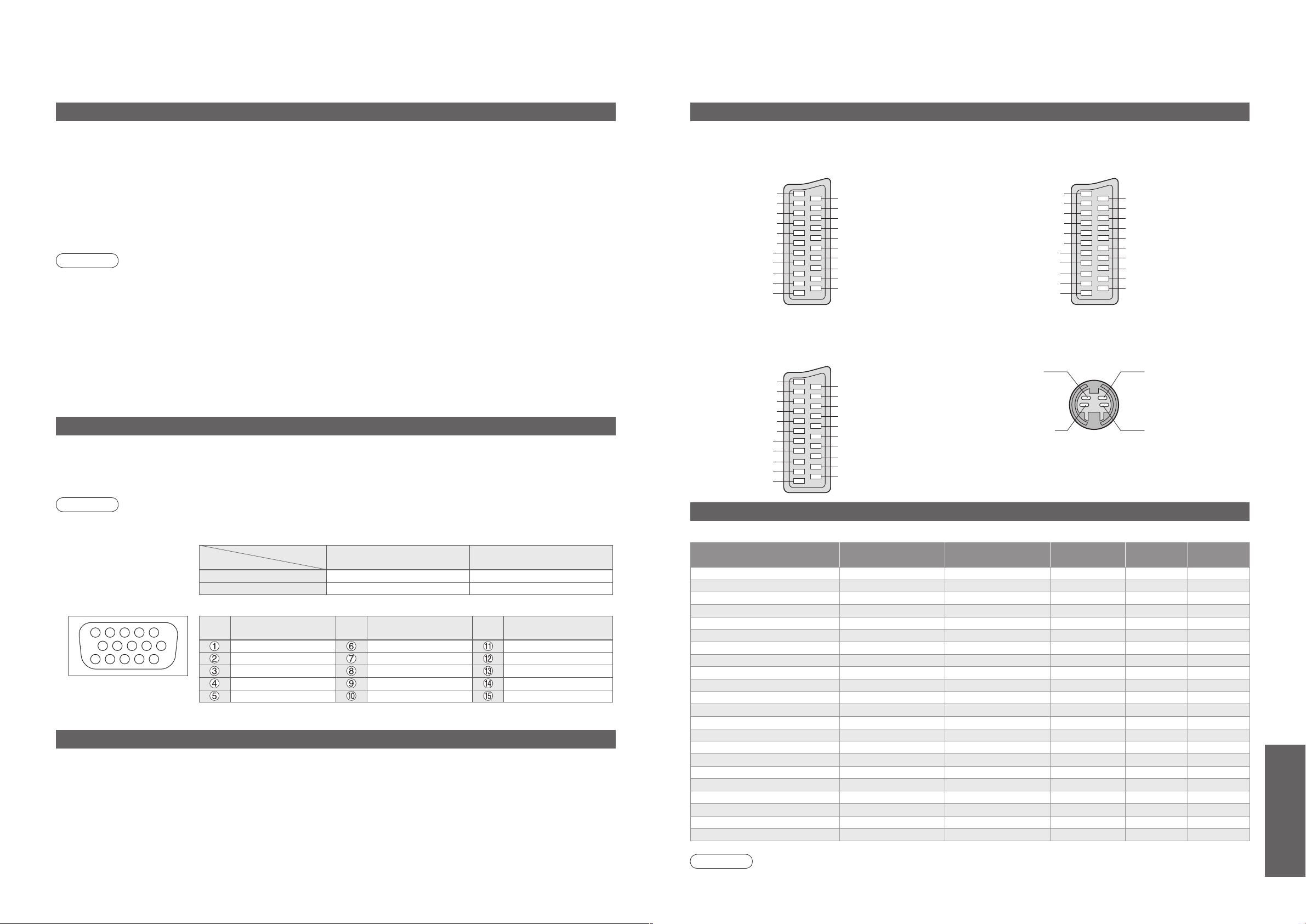
A PC may be connected to this TV unit so that the PC screen is displayed and sound is heard from the TV.
•
•
•
•
•
•
HDMI connections to some Panasonic equipments allow you to enjoy the easy playback or home theatre.
•
•
•
•
•
•
•
•
HDMI connection
HDMI is the world's first complete digital consumer AV interface complying with a non-compression standard.
If the external equipment has only a DVI output, connect to the HDMI1 terminal via a DVI to HDMI adapter cable (∗2).
When the DVI to HDMI adapter cable is used, connect the audio cable to the audio input terminal.
Audio settings can be made on the "HDMI1 input" menu screen. (p. 16)
Applicable audio signal sampling frequencies (2ch L.PCM): 48 kHz, 44.1 kHz, 32 kHz
(∗1): The HDMI logo is displayed on an HDMI-compliant equipment. (∗2): Enquire at your local digital equipment retailer shop.
Note
HDMI2 terminal is for digital signal only.
Use with a PC is not assumed.
The 720p/1080i signals will be reformatted before being displayed on the screen.
If the connected equipment has an aspect adjustment function, set the aspect ratio to "16:9".
These HDMI connectors are "type A".
An equipment having no digital output terminal may be connected to the input terminal of either "Component", "SVIDEO", or "Video" to receive analogue signals.
The HDMI input terminal can be used with only the following image signals:
480i, 480p, 576i, 576p, 720p and 1080i. Match the output setting of the digital equipment.
For details of the applicable HDMI signals, see p. 35.
PC connection
PC signals that can be inputted: Horizontal scanning frequency 31 to 69 kHz; vertical scanning frequency
59 to 86 Hz (more than 1,024 signal lines could result in incorrect display of the image).
A PC adapter is not necessary for the DOS/V-compliant D-sub 15-pin connector.
Note
Some PC models cannot be connected to this TV unit.
For details of the applicable PC signals, see p. 35.
Max. display resolution
Aspect
D-sub 15-pin connector signal
Pin No.
Model No.
4:3 768 × 720 dots 768 × 768 dots
16:9 1,024 × 720 dots 1,024 × 768 dots
Signal Name
R GND (Ground) NC (not connected)
G GND (Ground) NC (not connected)
B GND (Ground) HD/SYNC
NC (not connected) NC (not connected) VD
GND (Ground) GND (Ground) NC (not connected)
TH-37PX60E TH-42PX60E
Pin No.
Signal Name
Pin No.
Signal Name
Control with HDMI
Setup the equipment to enable this function. Read the manual of the equipment.
Switch the TV unit on again with the equipment on when connection or setup is changed.
This function may not work normally depending on the equipment condition.
The equipment can be operated by TV’s remote control with this function on even if TV is in Standby mode.
Image or sound may not be available for the first few seconds when the playback starts.
Image or sound may not be available for the first few seconds when Input mode is switched.
Volume function will be displayed when adjusting the volume of the equipment.
Easy playback is also available by using the remote control for Amplifier. Read the manuals of Amplifier.
SCART and S-video terminal information
AV1 SCART terminal
■
(RGB, VIDEO)
Suitable inputs for AV1 include RGB (Red / Green / Blue).
Socket Earth
CVBS out (video)
CVBS earth
Red in
Red earth
Green in
Green earth
Blue in
Blue earth
Audio out (L)
Audio out (R)
AV3 SCART terminal
■
21
19
17
15
13
11
9
7
5
3
1
CVBS in (video)
20
RGB status earth
18
Status RGB
16
Earth
14
--
12
--
10
Status CVBS
8
Audio in (L)
6
Audio earth
4
Audio in (R)
2
(RGB, VIDEO, S-VIDEO, Q-Link)
AV3 - Pins 15 and 20 are dependent on AV3 S-VHS /
VIDEO switching.
Socket Earth
CVBS out (video)
CVBS earth
Red in, S.C. - in
Red earth
Green in
Green earth
Blue in
Blue earth
Audio out (L)
Audio out (R)
21
19
17
15
13
11
9
7
5
3
1
CVBS in (video)
20
Earth
18
Status RGB
16
Earth
14
--
12
Q-Link data
10
Status CVBS
8
Audio in (L)
6
Audio earth
4
Audio in (R)
2
AV2 SCART terminal
■
(VIDEO, S-VIDEO, Q-Link)
AV2 - Pins 15 and 20 are dependent on AV2 S-VHS /
VIDEO switching.
Socket Earth
CVBS out (video)
CVBS earth
S.C. - in
Earth
-Earth
-Earth
Audio out (L)
Audio out (R)
AV4 S-VIDEO 4 pin terminal
■
Chrominance in
Chrominance earth Luminance earth
21
19
17
15
13
11
9
7
5
3
1
Input signal that can be displayed
∗
Mark: Applicable input signal for Component (Y, PB, PR), HDMI and PC (D-sub 15P)
Signal name
525 (480) / 60i 15.73 59.94
525 (480) / 60p 31.47 59.94
625 (576) / 50i 15.63 50.00
625 (576) / 50p 31.25 50.00
750 (720) / 60p 45.00 60.00
750 (720) / 50p 37.50 50.00
1,125 (1,080) / 60i 33.75 60.00
1,125 (1,080) / 50i 28.13 50.00
640 × 400 @70 Hz 31.46 70.07
640 × 480 @60 Hz 31.47 59.94
640 × 480 @75 Hz 37.50 75.00
800 × 600 @60 Hz 37.88 60.32
800 × 600 @75 Hz 46.88 75.00
800 × 600 @85 Hz 53.67 85.06
1,024 × 768 @60 Hz 48.36 60.00
1,024 × 768 @70 Hz 56.48 70.07
1,024 × 768 @75 Hz 60.02 75.03
1,024 × 768 @85 Hz 68.68 85.00
1,280 × 1,024 @60 Hz 63.98 60.02
Macintosh13” (640 × 480) 35.00 66.67
Macintosh16” (832 × 624) 49.72 74.54
Macintosh21” (1,152 × 870) 68.68 75.06
Note
Signals other than above may not be displayed properly.
•
The above signals are reformatted for optimal viewing on your display.
•
Horizontal
frequency (kHz)
Vertical
frequency (Hz)
Component HDMI PC
CVBS in (video)
20
Earth
18
--
16
Earth
14
--
12
Q-Link data
10
Status CVBS
8
Audio in (L)
6
Audio earth
4
Audio in (R)
2
Luminance in
∗ ∗
∗ ∗
∗ ∗
∗ ∗
∗ ∗
∗ ∗
∗ ∗
∗ ∗
•
Technical Information
∗
∗
∗
∗
∗
∗
∗
∗
∗
∗
∗
∗
∗
∗
Page 19
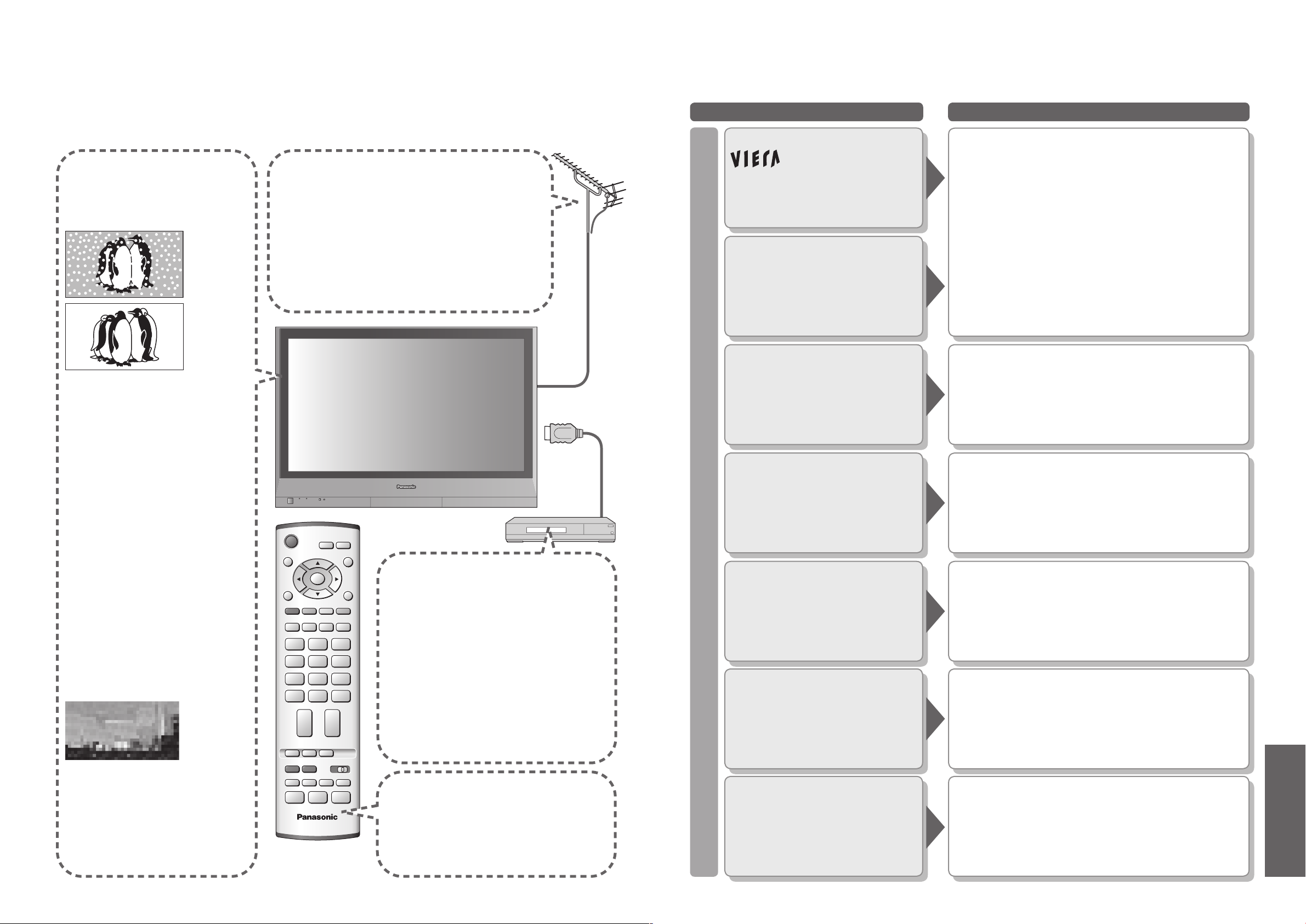
FAQs, etc.
IDTV
36
37
FAQs
Before requesting service or assistance, please follow these simple guides to resolve the problem.
If problem still persists, please contact your local Panasonic dealer or Panasonic Customer Care Centre
for assistance.
White spots or
To customer using indoor aerial
shadow images
(noise)
Check the position, direction,
•
and connection of the aerial.
In order to enjoy a good quality DVB image, it is
important to receive a good quality DVB signal. For
this purpose check "Signal Condition" in Tuning
Menu (p. 24). A level of at least 5 is required in order
to provide a good picture. It may be necessary to
adjust the position and direction of the aerial to
achieve the best possible result.
Problem Actions
logo appears at
the four corners of the
screen
Contrast is reduced
Only one part
remains dark
The function to prevent after-image is activated.
•
(Not a faulty symptom)
● The screen saver is activated if the TV unit is not
operated for a certain time in AV mode.
● Contrast is lowered when teletext, radio, menu,
etc. lasts for several minutes.
● "after-image" (p. 5)
A pixel or luminescent spot may occasionally be missing
•
in plasma displays.
(Not a faulty symptom)
No DVB
programmes shown
after Auto Setup
Check the DVB transmitter.
•
Adjust the direction of the aerial
•
to another transmitter installed
nearby.
Check the analogue broadcast.
•
If the image quality is poor,
check the aerial and consult
your nearest dealer.
Interference or
frozen / disappearing
image in DVB
Check "Signal Condition". (p. 24)
•
If "Signal Quality" or "Signal
Strength" are displayed in red
check aerial.
If problem persists consult your
local Panasonic dealer.
Turn the TV unit off with the On /
•
Off switch, then turn it on again.
Pictures from an
equipment are unusual
when the equipment is
connected via HDMI
Is the HDMI cable connected properly?
•
(p. 30)
Turn Off the TV unit and equipment,
•
then turn them On again.
Check an input signal from the equipment.
•
(p. 35)
Use an equipment compliant with
•
EIA/CEA-861/861B.
The remote control
does not work
Are the batteries installed correctly?
•
(p. 6)
Has the TV unit been switched On?
•
Screen
Chaotic image, noisy
No image can be
displayed
Blurry or
distorted image
(no sound or low volume)
Neither image nor
sound is produced
Set "P-NR" in the Picture menu (to remove noise).
•
(p. 16)
Check nearby electrical products
•
(car, motorcycle, fluorescent lamp).
Is "Colour" or "Contrast" in the Picture menu set to the
•
minimum? (p. 16)
Reset channels. (pp. 20 and 24)
•
Some programmes may not be received when both Aerial
•
and CATV signals are connected to the TV through a
mixer. In this case, connect either Aerial or CATV signal
directly to the TV.
Is the unit in "AV mode"?
•
Is the mains lead plugged into the socket outlet?
•
Is the TV unit turned On?
•
Check Picture menu (p. 16) and volume.
•
•
Frequently Asked Questions
Page 20
FAQs, etc.
38
39
FAQs
Problem Actions
Problem Actions
No sound is produced
Sound
Is "Sound Mute" active? (p. 7)
•
Is the volume set to the minimum?
•
Licence
Trademark Credits
DVB is a trademark of the DVB Digital Video Broadcasting Project (1991 to 1996).
•
VGA is a trademark of International Business Machines Corporation.
•
Macintosh is a registered trademark of Apple Computer, USA.
•
S-VGA is a registered trademark of the Video Electronics Standard Association.
•
Even if no special notation has been made of company or product trademarks, these trademarks have been fully respected.
HDMI, the HDMI Logo and High-Definition Multimedia Interface are trademarks or registered trademarks of
•
HDMI Licensing LLC.
Sound level is low
or sound is distorted
Due to the digital reception technologies involved, quality of the DTV signals may be relatively low in
•
some cases, despite good reception of analogue programmes.
DVB HDMI
Unable to receive
signals with a
high-performance
aerial
Sound is unusual
An error message
appears
"Control with HDMI"
function does not work
TV unit goes into
Other
"Standby mode"
An error message
appears
Sound signal reception may be deteriorated.
•
Set "MPX" (p. 16) in the Sound menu to "Mono".
•
(Analogue only)
Install an aerial individually for the TV unit and VCR
•
(or use a splitter).
TV
(Individual aerial)
Splitter
Aerial
Input
VCR
Set the sound setting of the connected equipment
•
to "2ch L.PCM".
Check the "HDMI1 input" setting in the Sound menu.
•
(p. 16)
If digital sound connection has a problem, select
•
analogue sound connection. (p. 34)
Contact the authorized Service Centre.
•
Switch the TV unit on again with the equipment on.
•
Set “Control with HDMI” to “Off”, then set to “On” again.
•
(p. 27)
The sleep function is activated.
•
The TV unit enters "Standby mode" about 30 min.
•
after broadcasting ends.
Follow the message's instructions.
•
If the problem persists, contact the authorized
•
Service Centre.
terminal
Aerial Output
Aerial Output
Aerial Input
(Individual aerial)
Trade Mark of the DVB Digital Video Broadcasting Project (1991 to 1996)
TH-37PX60E Declaration of Conformity No 3920, 10th January 2006
TH-42PX60E Declaration of Conformity No 3921, 10th January 2006
Specifications
Power Source
Power
Consumption
Average use 250 W 270 W
Standby condition
Plasma Display
panel
Drive method AC type
Aspect Ratio 16:9
Contrast Ratio Max 10000:1
Visible screen size
(No. of pixels)
Sound
Speaker
Audio Output 20 W (10 W + 10 W ), 10% THD
Headphones M3 (3.5 mm) Jack × 1
PC signals
Receiving Systems /
Band name
Aerial - Rear VHF / UHF
Operating Conditions
Connection Terminals
AV1 (Scart terminal) 21 Pin terminal (Audio/Video in, Audio/Video out, RGB in)
AV2 (Scart terminal) 21 Pin terminal (Audio/Video in, Audio/Video out, S-Video in, Q-Link)
AV3 (Scart terminal) 21 Pin terminal (Audio/Video in, Audio/Video out, RGB in, S-Video in, Q-Link)
AV4
Others
Output AUDIO L - R RCA PIN Type × 2 0.5 V[rms] (high impedance)
Dimensions ( W × H × D ) 917 mm × 645 mm × 95 mm 1,020 mm × 705 mm × 95 mm
Weight
Note
Design and Specifications are subject to change without notice. Weight and Dimensions shown are approximate.
•
This equipment complies with the EMC standards listed below.
•
EN55013, EN61000-3-2, EN61000-3-3, EN55020, EN55022, EN55024.
VIDEO
S-VIDEO
AUDIO L - R RCA PIN Type × 2 0.5 V[rms]
COMPONENT
HDMI1/2 TYPE A Connectors
PC
AUDIO L - R RCA PIN Type × 2 0.5 V[rms]
AC 220-240 V, 50 / 60 Hz
0.3 W (Without Tuner Lock On)
20 W (With Tuner Lock On)
94 cmV 106 cmV
818 mm (W) × 461 mm (H) × 939 mm (diagonal) 920 mm (W) × 518 mm (H) × 1,056 mm (diagonal)
737,280 (1,024 (W) × 720 (H))
[3,072 × 720 dots]
12 cm × 6 cm × 2 pcs, 8
VGA, SVGA, XGA
SXGA ······ (compressed)
Horizontal scanning frequency 31 - 69 kHz
Vertical scanning frequency 59 - 86 Hz
PAL B, G, SECAM B, G, SECAM L / L’
VHF E2 - E12 UHF E21 - E69
CATV (S01 - S05) CATV S1 - S10 (M1 - M10)
CATV S11 - S20 (U1 - U10) CATV S21 - S41 (Hyperband)
PAL 525/60 : Playback of NTSC tape from some PAL Video recorders (VCR).
DVB : Digital terrestrial services via VHF / UHF aerial input.
M.NTSC : Playback from M.NTSC Video recorders (VCR).
NTSC (AV input only) : Playback from NTSC Video recorders (VCR).
TV signals may not be received in some areas.
•
Temperature : 0 °C - 40 °C
Humidity : 20 % - 80 % RH (non-condensing)
RCA PIN Type × 1 1.0 V[p-p] (75
Mini DIN 4-pin Y:1.0 V[p-p] (75
Y 1.0 V[p-p] (including synchronization)
PB, PR ±0.35 V[p-p]
HIGH-DENSITY D-SUB 15PIN R,G,B/0.7 V[p-p] (75
HD, VD/TTL Level 2.0 - 5.0 V[p-p] (high impedance)
26.0 k Net 30.0 k Net
TH-37PX60E TH-42PX60E
786,432 (1,024 (W) × 768 (H))
[3,072 × 768 dots]
Ω
Ω
)
Ω
) C:0.286 V[p-p] (75 Ω)
Ω
)
•
Frequently Asked Questions
•
Licence / Specifications
 Loading...