

Page 1
Order Number ITD1009085CE
FULL HD LCD Display
Model No. TH-42LF20E
TABLE OF CONTENTS
1 Safety Precautions----------------------------------------------- 3
1.1. General Guidelines---------------------------------------- 3
1.2. Touch-Current Check------------------------------------- 3
2 Warning -------------------------------------------------------------- 4
2.1. Prevention of Electrostatic Discharge (ESD)
to Electrostatically Sensitive (ES) Devices---------- 4
2.2. About lead free solder (PbF)---------------------------- 5
3 Service Navigation ----------------------------------------------- 6
3.1. Applicable signals ----------------------------------------- 6
4 Specifications ----------------------------------------------------- 8
5 Operating Instructions------------------------------------------ 9
6 Service Mode ----------------------------------------------------- 11
6.1. Service Menu Function (1) -----------------------------11
6.2. Service Menu Function (2) -----------------------------12
6.3. Service Mode Function (1) -----------------------------13
6.4. Service Mode Function (2) -----------------------------14
7 Troubleshooting Guide----------------------------------------15
8 Disassembly and Assembly Instructions ---------------16
8.1. Flowchart for disassembly------------------------------16
Model No.
PAG E PAG E
8.2. Preparations ----------------------------------------------- 17
8.3. Pedestal (option) removal------------------------------ 17
8.4. Rear cover removal-------------------------------------- 17
8.5. Replacement method for main board and jack
8.6. Replacement method for Power board ------------- 19
8.7. Replacement method for AC cord bracket -------- 19
8.8. Cabinet back removal (42 type) ---------------------- 20
8.9. Cabinet back removal (47 type) ---------------------- 20
8.10. When removing the cabinet back with the
8.11. Replacement method for speakers------------------ 20
8.12. Key SW board replacement --------------------------- 20
8.13. Connector board removal ------------------------------ 21
8.14. LCD panel replacement -------------------------------- 21
8.15. Replacement method for RC+LED board---------- 22
8.16. Cabinet front replacement ----------------------------- 22
8.17. Cabinet back replacement ----------------------------- 23
9 Block Diagram --------------------------------------------------- 27
TH-47LF20E
board -------------------------------------------------------- 18
board connected ----------------------------------------- 20
© Panasonic Corporation 2010
Unauthorized copying and distribution is a violation
of law.
Page 2

TH-42LF20E / TH-47LF20E
9.1. Block (1 of 2) Diagram ---------------------------------- 27
9.2. Block (2 of 2) Diagram ---------------------------------- 28
10 Wiring Connection Diagram --------------------------------- 29
10.1. Wiring Connection Diagram (1)----------------------- 29
10.2. Wiring Connection Diagram (2)----------------------- 31
10.3. Wiring Connection Diagram (3)----------------------- 32
10.4. Wiring Connection Diagram (4)----------------------- 33
11 Exploded View and Replacement Parts List ----------- 34
11.1. Exploded View and Mechanical Replacement
Parts List --------------------------------------------------- 34
11.2. Mechanical Replacement Parts List (42 inch) ---- 50
11.3. Mechanical Replacement Parts List (47 inch) ---- 51
11.4. Electrical Replacement Boards list (42 inch)------ 52
11.5. Electrical Replacement Boards list (47 inch)------ 52
11.6. Boards Layout--------------------------------------------- 52
2
Page 3
TH-42LF20E / TH-47LF20E
1 Safety Precautions
1.1. General Guidelines
1. When conducting repairs and servicing, do not attempt to modify the equipment, its parts or its materials.
2. When wiring units (with cables, flexible cables or lead wires) are supplied as repair parts and only one wire or some of the
wires have been broken or disconnected, do not attempt to repair or re-wire the units. Replace the entire wiring unit instead.
3. When conducting repairs and servicing, do not twist the Fasten connectors but plug them straight in or unplug them straight
out.
4. When servicing, observe the original lead dress.If a short circuit is found, replace all parts which have been overheated or
damaged by the short circuit.
5. After servicing, see to it that all the protective devices such as insulation barriers, insulation papers shields are properly
installed.
6. After servicing, make the following leakage current checks to prevent the customer from being exposed to shock hazards.
1.2. Touch-Current Check
1. Plug the AC cord directly into the AC outlet. Do not use an isolation transformer for this check.
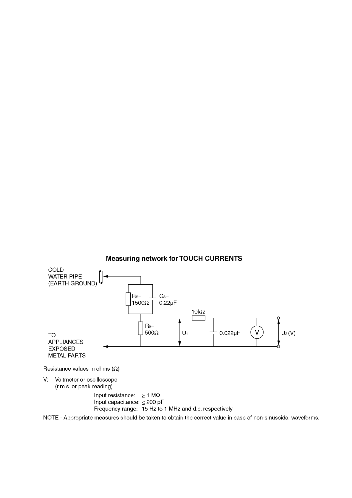
2. Connect a measuring network for touch currents between each exposed metallic part on the set and a good earth ground
such as a water pipe, as shown in Figure 1.
3. Use Leakage Current Tester (Simpson 228 or equivalent) to measure the potential across the measuring network.
4. Check each exposed metallic part, and measure the voltage at each point.
5. Reserve the AC plug in the AC outlet and repeat each of the above measure.
6. The potential at any point (TOUCH CURRENT) expressed as voltage U
For a. c.: U
For d. c.: U
Note:
The limit value of U
mA d. c.
The limit value U
7. In case a measurement is out of the limits specified, there is a possibility of a shock hazard, and the equipment should be
repaired and rechecked before it is returned to the customer.
= 35 V (peak) and U2 = 0.35 V (peak);
1
= 1.0 V,
1
= 0.35 V (peak) for a. c. and U1 = 1.0 V for d. c. correspond to the values 0.7 mA (peak) a. c. and 2.0
2
= 35 V (peak) for a. c. correspond to the value 70 mA (peak) a. c. for frequencies greater than 100 kHz.
1
and U2, does not exceed the following values:
1
Figure 1
3
Page 4

TH-42LF20E / TH-47LF20E
2 Warning
2.1. Prevention of Electrostatic Discharge (ESD) to Electrostatically Sensitive (ES) Devices
Some semiconductor (solid state) devices can be damaged easily by static electricity. Such components commonly are called Electrostatically Sensitive (ES) Devices. Examples of typical ES devices are integrated circuits and some field-effect transistors and
semiconductor “chip” components. The following techniques should be used to help reduce the incidence of component damage
caused by electrostatic discharge (ESD).
1. Immediately before handling any semiconductor component or semiconductor-equipped assembly, drain off any ESD on your
body by touching a known earth ground. Alternatively, obtain and wear a commercially available discharging ESD wrist strap,
which should be removed for potential shock reasons prior to applying power to the unit under test.
2. After removing an electrical assembly equipped with ES devices, place the assembly on a conductive surface such as aluminum foil, to prevent electrostatic charge buildup or exposure of the assembly.
3. Use only a grounded-tip soldering iron to solder or unsolder ES devices.
4. Use only an anti-static solder removal device. Some solder removal devices not classified as “anti-static (ESD protected)” can
generate electrical charge sufficient to damage ES devices.
5. Do not use freon-propelled chemicals. These can generate electrical charges sufficient to damage ES devices.
6. Do not remove a replacement ES device from its protective package until immediately before you are ready to install it. (Most
replacement ES devices are packaged with leads electrically shorted together by conductive foam, aluminum foil or comparable conductive material).
7. Immediately before removing the protective material from the leads of a replacement ES device, touch the protective material
to the chassis or circuit assembly into which the device will be installed.
Caution
Be sure no power is applied to the chassis or circuit, and observe all other safety precautions.
8. Minimize bodily motions when handling unpackaged replacement ES devices. (Otherwise ham less motion such as the brushing together of your clothes fabric or the lifting of your foot from a carpeted floor can generate static electricity (ESD) sufficient
to damage an ES device).
4
Page 5
TH-42LF20E / TH-47LF20E
2.2. About lead free solder (PbF)
Note: Lead is listed as (Pb) in the periodic table of elements.
In the information below, Pb will refer to Lead solder, and PbF will refer to Lead Free Solder.
The Lead Free Solder used in our manufacturing process and discussed below is (Sn+Ag+Cu).
That is Tin (Sn), Silver (Ag) and Copper (Cu) although other types are available.
This model uses Pb Free solder in it’s manufacture due to environmental conservation issues. For service and repair work, we’d
suggest the use of Pb free solder as well, although Pb solder may be used.
PCBs manufactured using lead free solder will have the PbF within a leaf Symbol PbF stamped on the back of PCB.
Caution
• Pb free solder has a higher melting point than standard solder. Typically the melting point is 50 ~ 70 °F (30~40 °C) higher. Please
use a high temperature soldering iron and set it to 700 ± 20 °F (370 ± 10 °C).
• Pb free solder will tend to splash when heated too high (about 1100 °F or 600 °C).
If you must use Pb solder, please completely remove all of the Pb free solder on the pins or solder area before applying Pb solder. If this is not practical, be sure to heat the Pb free solder until it melts, before applying Pb solder.
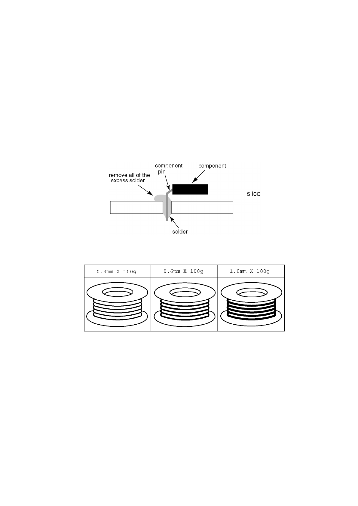
• After applying PbF solder to double layered boards, please check the component side for excess solder which may flow onto the
opposite side. (see figure below)
Suggested Pb free solder
There are several kinds of Pb free solder available for purchase. This product uses Sn+Ag+Cu (tin, silver, copper) solder. However, Sn+Cu (tin, copper), Sn+Zn+Bi (tin, zinc, bismuth) solder can also be used.
5
Page 6
TH-42LF20E / TH-47LF20E
3 Service Navigation
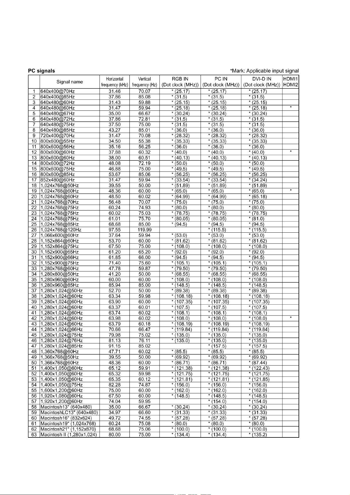
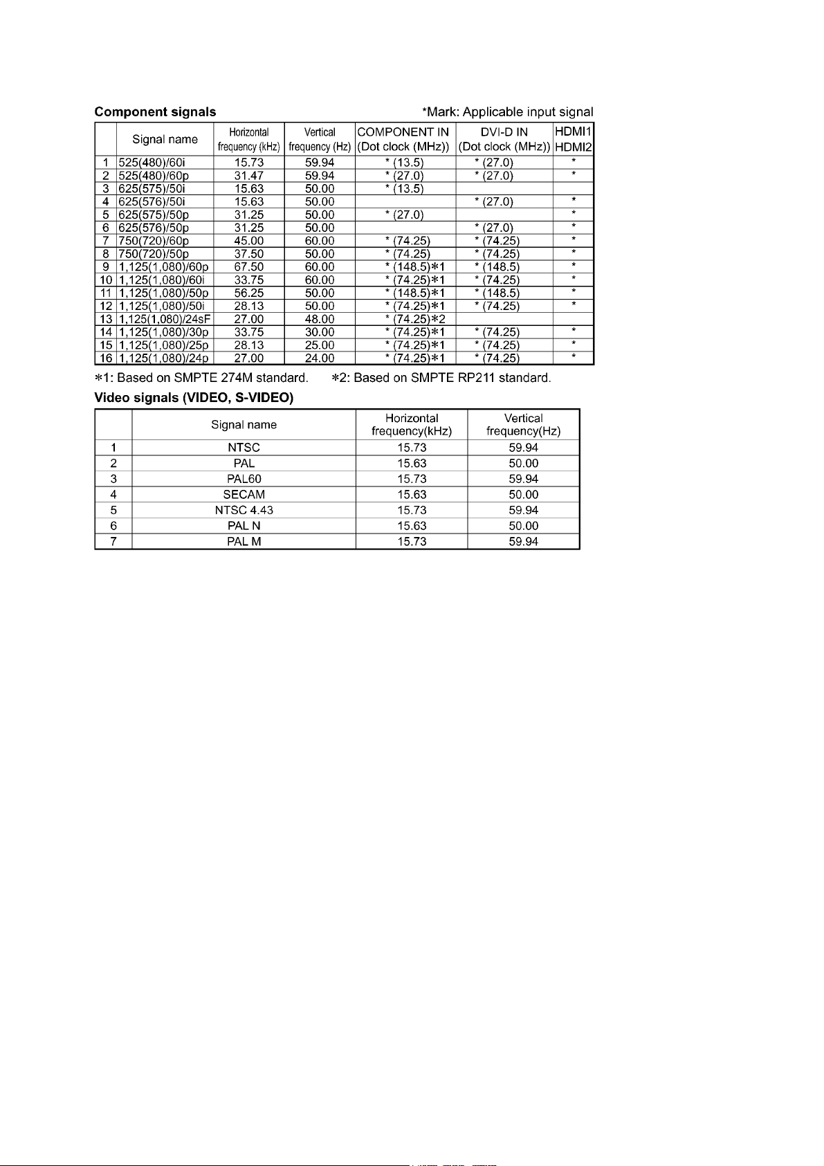
3.1. Applicable signals
6
Page 7
TH-42LF20E / TH-47LF20E
7
Page 8

TH-42LF20E / TH-47LF20E
4 Specifications
Power Source 220 - 240 V AC, 50/60Hz
Power Consumption
Power on 240 W (42 inch) 290 W (47 inch)
Stand-by condition 0.2 W (42 inch) 0.2 W (47 inch)
Power off condition 0.2 W (42 inch) 0.2 W (47 inch)
LCD Display panel 42-inch IPS panel, 16:9 aspect ratio (42 inch) 47-inch IPS panel, 16:9 aspect ratio (47 inch)
Screen size 930 mm (W) × 523 mm (H) × 1,067 mm (diagonal) (42 inch)
1,040 mm (W) × 585 mm (H) × 1,193 mm (diagonal) (47 inch)
(No.of pixels) 2,073,600 (1,920 (W) × 1,080 (H)) (42 inch) 2,073,600 (1,920 (W) × 1,080 (H)) (47 inch)
[5,760 × 1,080 dots] [5,760 × 1,080 dots]
Operating condition
Temperature 0 °C - 40 °C
Humidity 20 % - 80 %
Applicable signals
Colour System NTSC, PAL, PAL60, SECAM, NTSC 4.43, PAL M, PAL N
Scanning format
PC signals VGA, SVGA, XGA, SXGA
Connection terminals
AV IN VIDEO BNC 1.0 Vp-p (75-ohm)
S-VIDEO Mini DIN 4PIN Y: 1.0 Vp-p (75-ohm), C: 0.286 Vp-p (75-ohm)
AUDIO L-R RCA Pin jack × 2 0.5 Vrms
HDMI 1/2 TYPE A Connector
COMPONENT / RGB IN
G/Y BNC with sync 1.0 Vp-p (75-ohm)
B/P
B/CB
R/P
R/CR
AUDIO L-R RCA Pin jack × 2 0.5 Vrms
DVI-D IN DVI-D 24 Pin Compliance with DVI Revision 1.0
AUDIO Stereo mini jack (M3) × 1 0.5 Vrms, Shared with PC IN
PC IN High-Density Mini D-sub 15 Pin G with sync 1.0 Vp-p (75-ohm)
AUDIO Stereo mini jack (M3) × 1 0.5 Vrms, Shared with DVI-D IN
SERIAL External Control Terminal
Sound
Speakers 50 mm × 90 mm × 2 pcs
Audio Output 10 W [5 W + 5 W] (10 % THD)
Accessories Supplied
Remote Control Transmitter N2QAYB000535
Batteries R6 Size × 2
Clamper TMME289 × 3
Dimensions (W × H × D) 968 mm × 561 mm × 101 mm (42 inch) 1,079 mm × 624 mm × 101 mm (47 inch)
Mass (weight) approx. 18.0 kg (42 inch) approx. 23.0 kg (47 inch)
Note:
• Design and specifications are subject to change without notice. Mass and dimensions shown are approximate.
• This equipment complies with the EMC standards listed below.
EN55022, EN55024, EN61000-3-2, EN61000-3-3.
525 (480) / 60i 60p, 625 (575) / 50i 50p, 750 (720) / 60p 50p, 1125 (1080) /
60i 60p 50i 50p 24p 25p 30p 24sF, 1250 (1080) / 50i
UXGA ..... (compressed)
Horizontal scanning frequency 30 - 110 kHz
Vertical scanning frequency 48 - 120 Hz
BNC 0.7 Vp-p (75-ohm)
BNC 0.7 Vp-p (75-ohm)
Content Protection Compatible with HDCP 1.1
G without sync 0.7 Vp-p (75-ohm)
B:0.7 Vp-p (75-ohm)
R:0.7 Vp-p (75-ohm)
HD / VD:1.0 - 5.0 Vp-p (high impedance)
VBS (use HD port) with picture 1.0 Vp-p (high impedance)
without picture 0.3 Vp-p (high impedance)
D-sub 9 Pin RS-232C compatible
8
Page 9
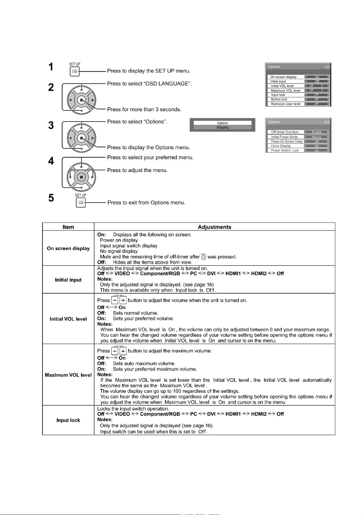
5 Operating Instructions
TH-42LF20E / TH-47LF20E
9
Page 10
TH-42LF20E / TH-47LF20E
10
Page 11
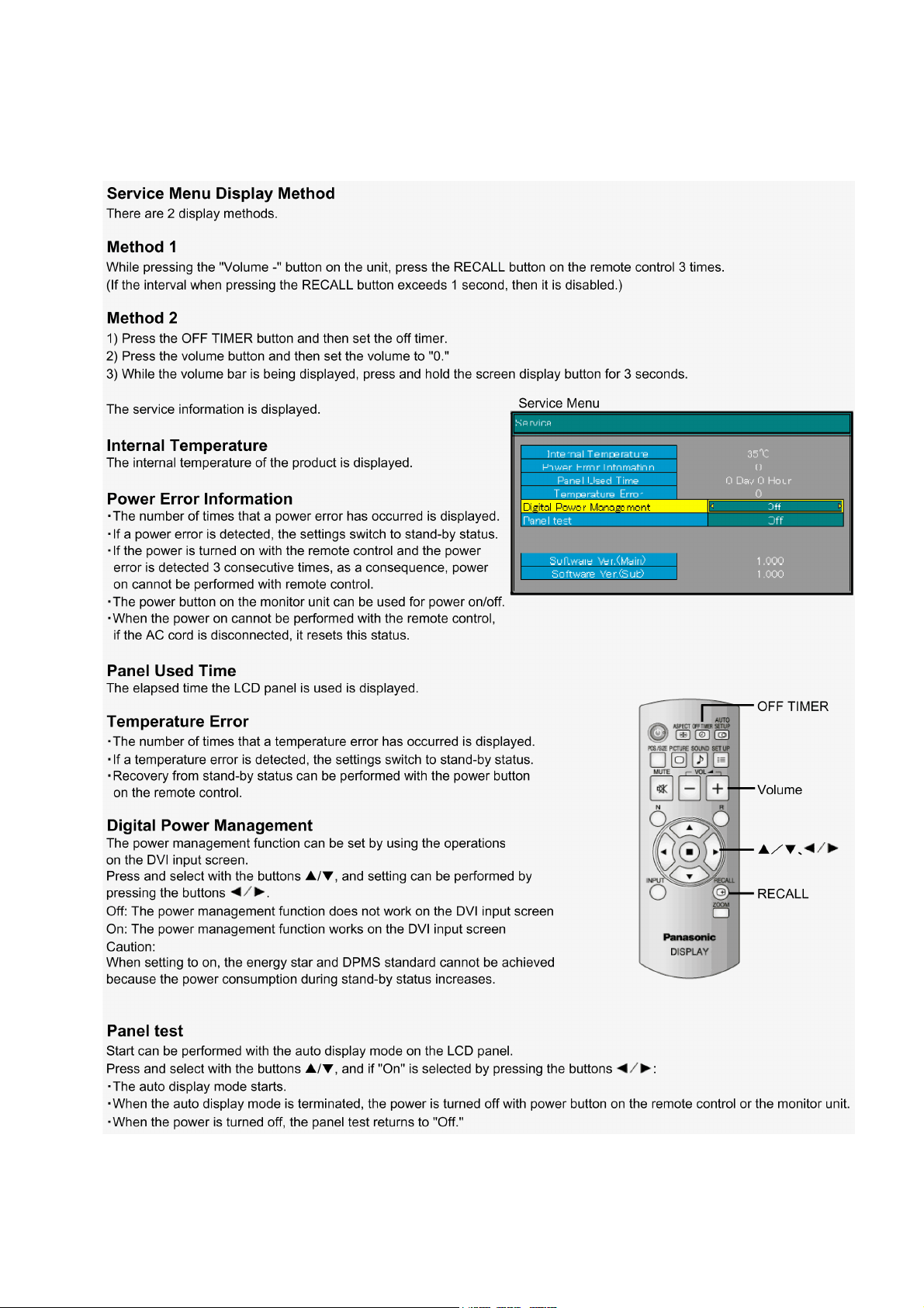
6 Service Mode
6.1. Service Menu Function (1)
TH-42LF20E / TH-47LF20E
11
Page 12
TH-42LF20E / TH-47LF20E
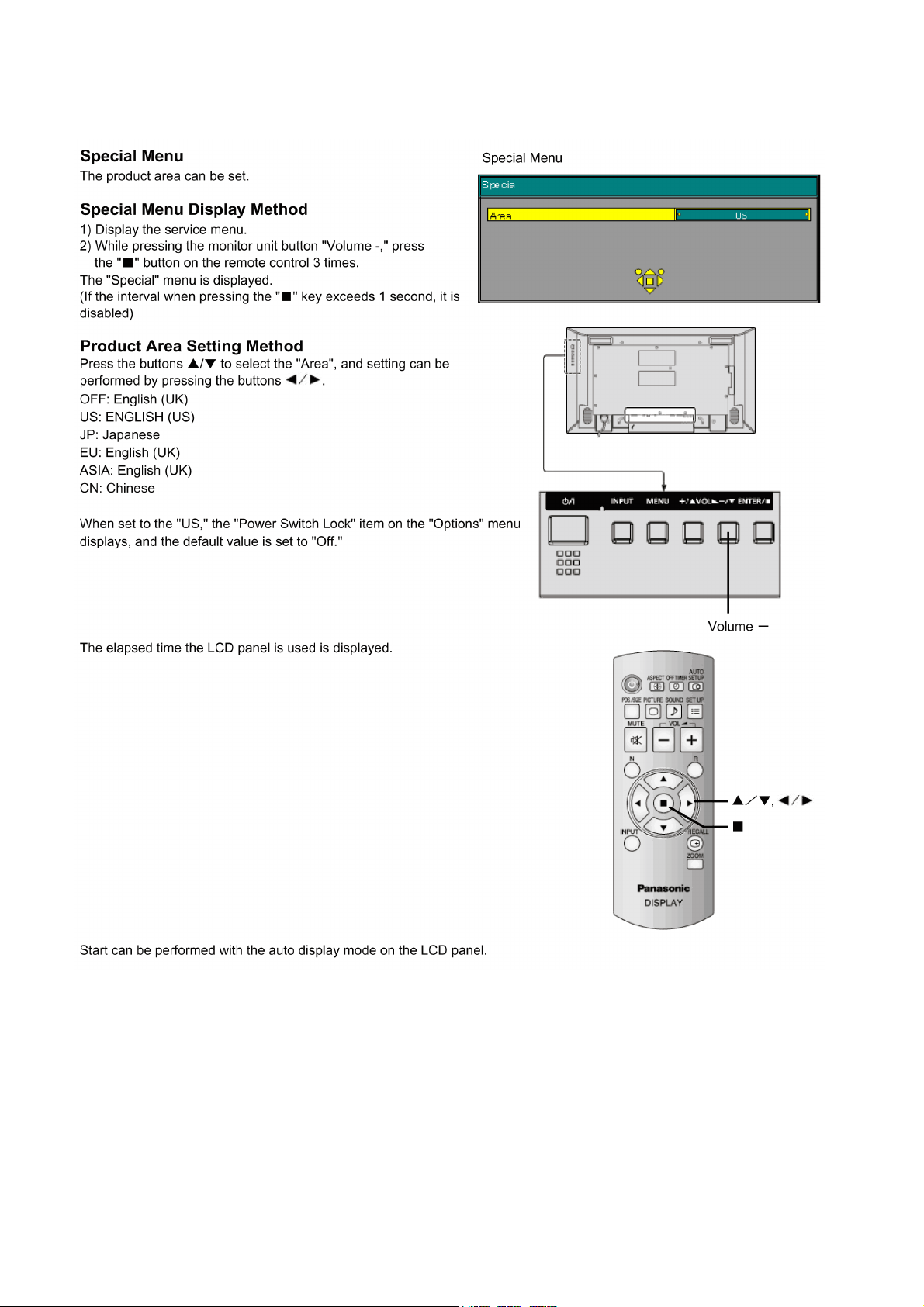
6.2. Service Menu Function (2)
12
Page 13
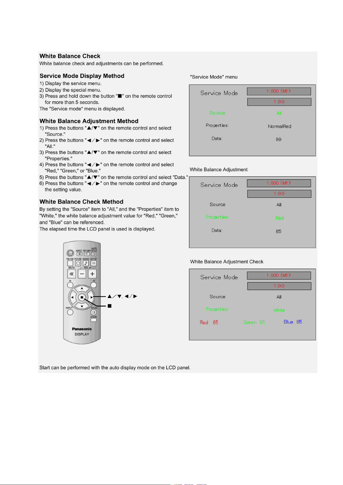
6.3. Service Mode Function (1)
TH-42LF20E / TH-47LF20E
13
Page 14
TH-42LF20E / TH-47LF20E
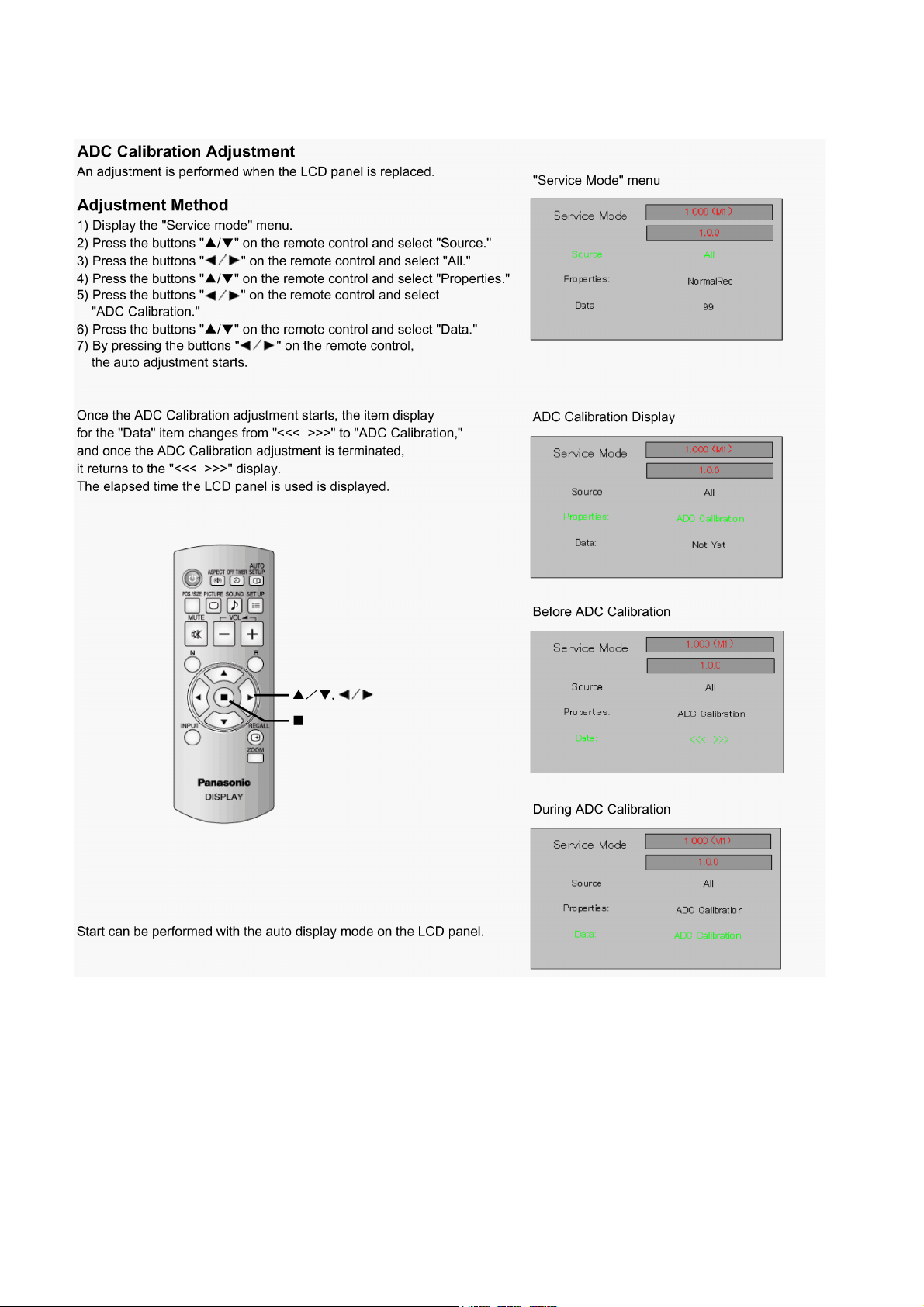
6.4. Service Mode Function (2)
14
Page 15
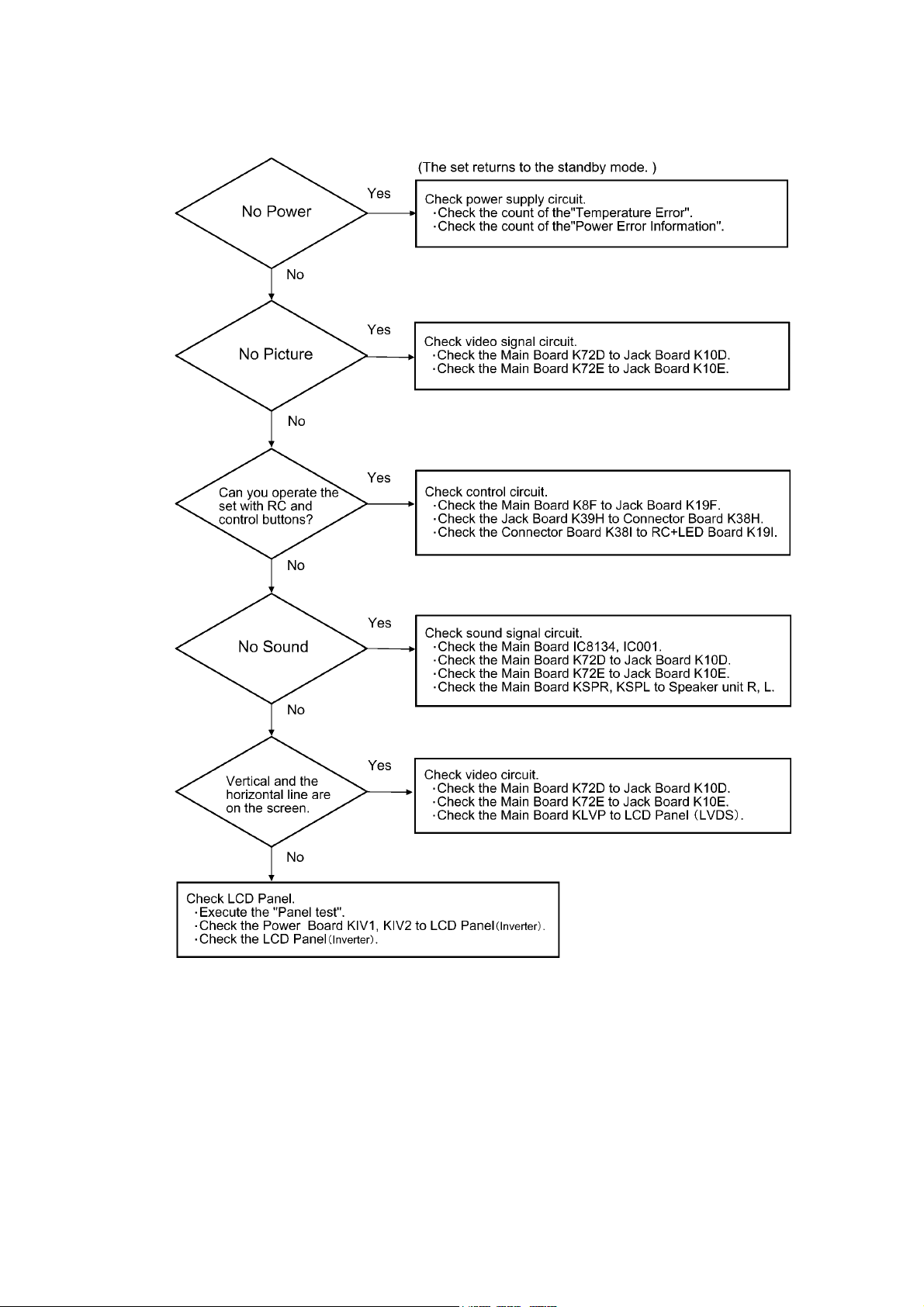
7 Troubleshooting Guide
TH-42LF20E / TH-47LF20E
15
Page 16
TH-42LF20E / TH-47LF20E
8 Disassembly and Assembly Instructions
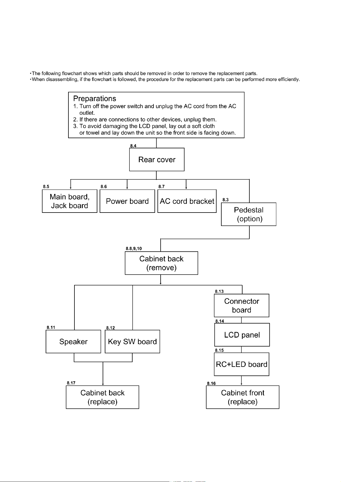
8.1. Flowchart for disassembly
16
Page 17
TH-42LF20E / TH-47LF20E
8.2. Preparations
To avoid damaging the LCD panel, lay out a soft cloth or towel
and lay down the unit so the front side is facing down.
Precautions when replacing each module
• Always perform the procedure below when replacing each
module.
• Be careful not to overtighten the screws when installing each
module.
8.3. Pedestal (option) removal
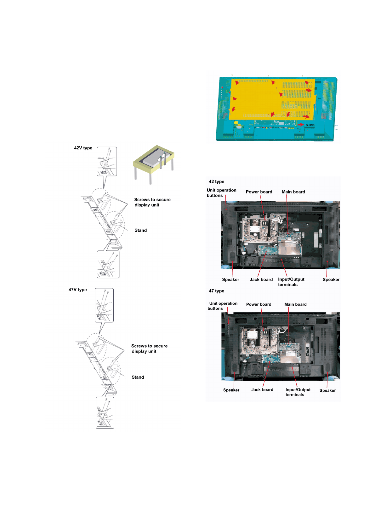
If the pedestal (option) is installed, remove the 2 screws for the
pedestal on each side, and then remove the pedestal.
8.4. Rear cover removal
First remove the 10 screws on the rear cover, and then remove
the rear cover. (SCR TPG BRZ 4x10)
Boards & Parts location
This unit is designed so that removing the rear cover reveals
the configuration of the boards.
17
Page 18
TH-42LF20E / TH-47LF20E
8.5. Replacement method for main
board and jack board
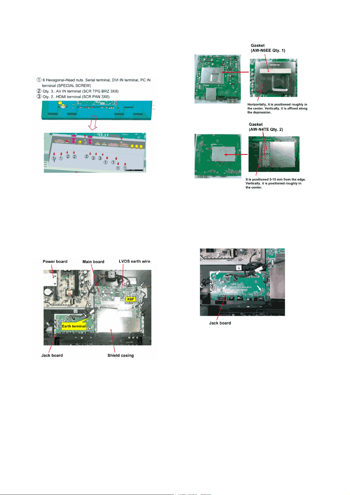
1. The terminal section is screwed in from the outside, so
remove the screws as shown in the illustration.
2. Remove 1 screw on the jack board that screws in the
earth terminal which comes off from the left side of the
main board. (SCR PAN+SW+W 3X8)
3. Remove the 7 screws that screw the shield casing onto
the main board. (SCR PAN+SW+W 3X8)
4. Remove the coupler that is connected to the main board,
and then carefully remove the main board. Couplers on
the main board:
K16C, KSPR, KSPL, KLVP, K16B, K16A, K8F, K72E,
K72D
5. Replace the main board with the replacement board.
6. Remove the 4 screws that screw in the jack board.
(SCR PAN+SW+W 3X8)
7. Remove the couplers that is connected to the jack board
and carefully remove the jack board.
Couplers on the jack board: K39H, K39G, K19F, K10E,
K10D
8. Replace the jack board with the replacement board.
Precautions when removing and installing
• The lead wire is affixed to the shield casing on the main
board with aluminum foil tape. Re-use the shield casing
with the lead wire affixed as is.
• The gasket is affixed to both sides of the main board.
The gasket is not included on the replacement board, so
replace the gasket at the same time as well.
18
Page 19
TH-42LF20E / TH-47LF20E
8.6. Replacement method for
Power board
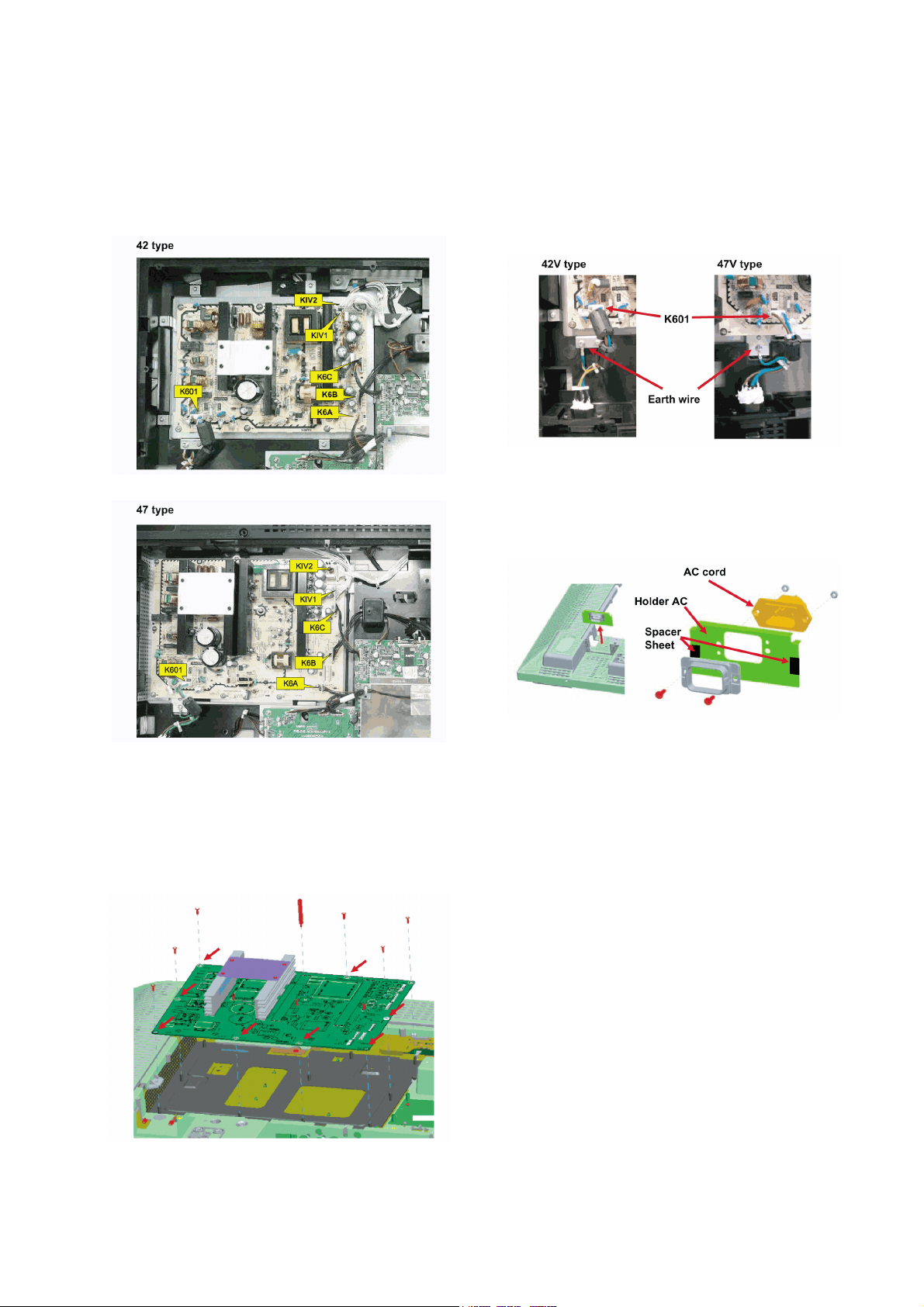
1. Remove the couplers that are connected to the Power
board.
Couplers on the Power board: K601, KIV2, KIV1, K6C,
K6B, K6A
8.7. Replacement method for AC
cord bracket
1. Remove the K601 connector for the AC cord bracket from
the Power board.
2. Remove 1 screw that screws in the earth wire for the AC
cord.
Screw: SCR BIN 4X6
3. Pull out the AC cord bracket from the slit on the cabinet
back.
4. Remove the screws (Qty. 2) and nuts (Qty. 2) shown in
the illustration, and then remove the AC cord component.
Screw: SCR BRZ 3X10, Nut: NUT HEX 3
2. Remove the screws (47V type: 9 screws, 42V type: 8
screws) that screw the Power board in place. (SCR
PAN+SW+W 3X8) Pull out the boss (plastic) that holds
the Power board.
3. Remove the Power board carefully and replace it with the
replacement board. (The replacement board is equipped
with a fuse.)
5. Replace the AC cord.
Precautions when removing and installing
• The lead wire is affixed to the shield casing on the main
board with aluminum foil tape. Re-use the shield casing
with the lead wire affixed as is.
• The gasket is affixed to both sides of the main board.
The gasket is not included on the replacement board, so
replace the gasket at the same time as well.
19
Page 20
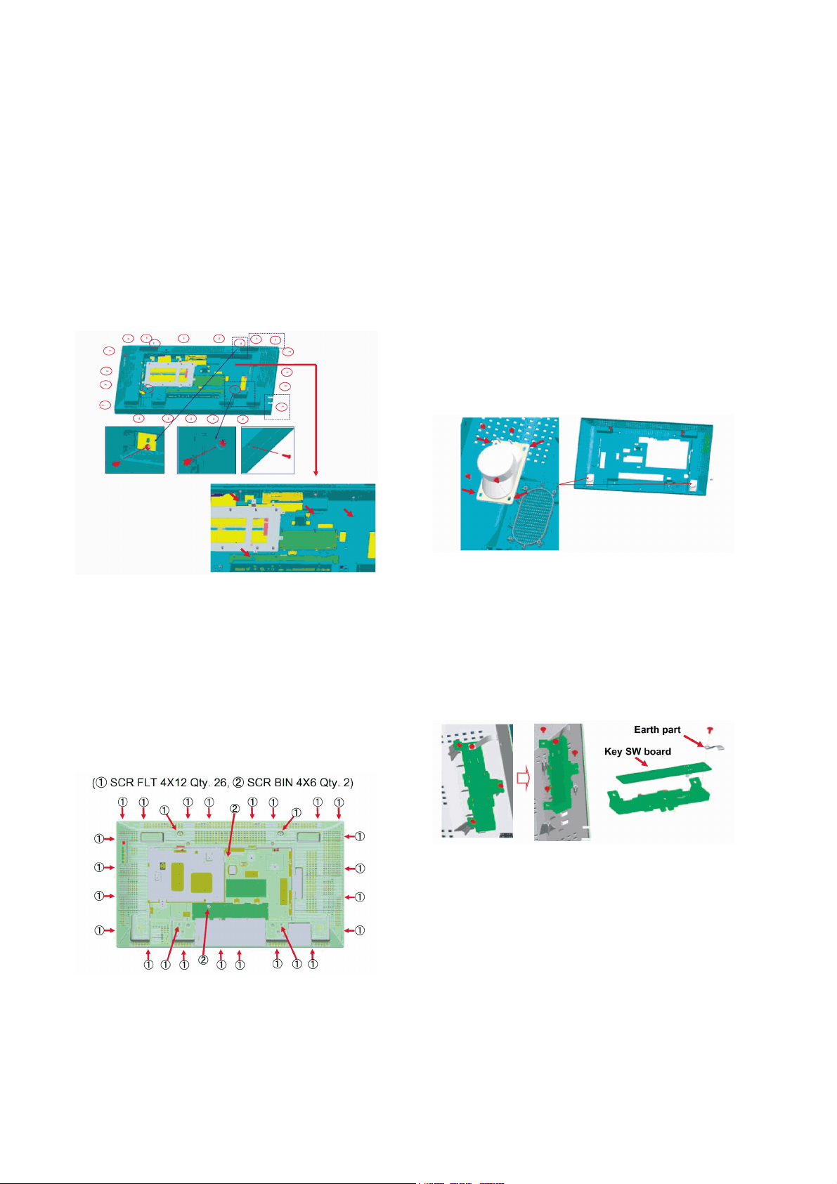
TH-42LF20E / TH-47LF20E
8.8. Cabinet back removal (42 type)
Precautions when removing and installing
• Be careful not to strip the screw's thread, etc., as the screws
that screw into the cabinet back's periphery impact the outward appearance.
• When re-installing the rear cover, be careful which holes the
wires come out from. (Refer to the wiring connection diagram)
1. Remove the screws (Qty. 23) on the periphery of the cabinet back. (SCR FLT 4X12)
2. Remove the screws (Qty. 4) on the inside part of the rear
cover. (SCR BIN 4X6)
3. Remove the cabinet back carefully.
8.10. When removing the cabinet
back with the board connected
1. Remove the following board couplers.
Jack board: K39H
Main board: KLVP
Power board: KIV1, KIV2
2. Remove according to the previous section "Cabinet back
removal".
8.11. Replacement method for
speakers
1. Remove the cabinet back.
2. Peel off the tape halfway that affixes the speaker lead on
the inside of the cabinet back, and then remove the
speaker lead. (Refer to the wiring connection diagram)
3. Remove the screws (Qty. 4 on each side) that screw in
the speaker unit and then replace it with the repair
speaker unit. (SCR S-TPG BRZ+FLG 3.0X8.0 V)
8.9. Cabinet back removal (47 type)
Precautions when removing and installing
• Be careful not to strip the screw's thread, etc., as the screws
that screw into the cabinet back's periphery impact the outward appearance.
• When re-attaching the cabinet back, be careful which holes
the wires come out from. (Refer to the wiring connection diagram)
1. Remove the screws.
2. Remove the cabinet back carefully.
8.12. Key SW board replacement
1. Remove the cabinet back.
2. Peel off the tape halfway that affixes the lead wire for the
key SW board on the inside of the cabinet back, and then
remove the lead wire. (Refer to the wiring connection diagram)
3. Remove the 4 screws and replace the key SW board.
(SCR S-TPG BRZ+FLG 3.0X8.0 V)
Precautions when installing
• The lead wire is affixed to the shield casing on the main
board with the earth part on the key SW board, do not
forget to install so the key SW board is at a right
angle.minum foil tape. Re-use the shield casing with the
lead wire affixed as is.
• Secure the speaker and key SW board lead wires down
onto the inside of the cabinet back with tape so they do
not pop up.
• When re-attaching the rear cover, be careful which holes
the wires come out from. (Refer to the wiring connection
diagram)
20
Page 21
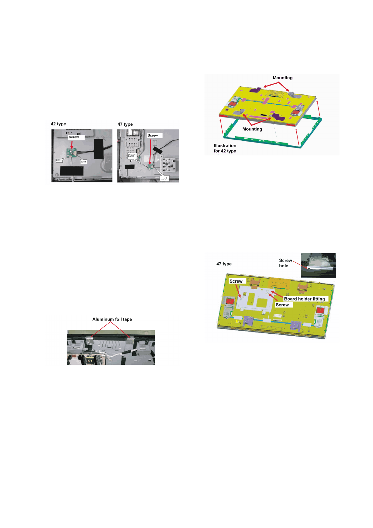
TH-42LF20E / TH-47LF20E
8.13. Connector board removal
1. Peel off the tape halfway that affixes the FFC cable and
lead wire for the connector board to the rear side of the
LCD panel, and remove them from the rear side of the
panel. (Refer to the wiring connection diagram)
2. Remove the FFC cable (K38I) and the coupler (K38H)
from the connector board.
3. Remove the screw (Qty. 1), and remove the connector
board from the rear side of the LCD panel, and then
replace. (SCR PAN+SW 4X6)
8.14. LCD panel replacement
Precautions when replacing the LCD panel
• The 2 lead wires for the inverter (Couplers KIV1 and KIV2),
the black-out tape and the spacer sheet, etc., are supplied
already affixed to the LCD panel.
• The tape that is affixed to the FFC cable and the lead wires
on the connector board are supplied as repair parts. Replace
them at the same time as the LCD panel.
3. While widening the mounting that connects the cabinet
front and the LCD panel, remove the cabinet front from
the LCD panel. When lifting up the LCD panel, hold the
mounting component.
4. Remove the screws (Qty. 8), and then remove the mounting from the rear side of the LCD panel. (SCR BIN 4X6)
5. (47V type only) Remove the screws (Qty. 2) and then
remove the Power board holder fittings from the rear side
panel. (SCR BIN 4X4)
• The Power board holder fittings are not available in the
repair parts.
6. Replace the LCD panel with the replacement LCD panel.
7. Use 2 pieces of replacement aluminum foil tape and
cover the screw hole on the upper part of the mounting so
it is affixed to and crosses over the mounting top and the
rear side of the LCD panel.
1. Follow the procedure mentioned previously, and remove
the connector board, the FFC cable and the lead wire
from rear side of the LCD panel.
2. Peel off the 2 pieces of aluminum foil tape that are affixed
to and cross over the rear side of the LCD panel and the
upper part of the mounting that connects the cabinet front
and LCD panel.
21
Page 22
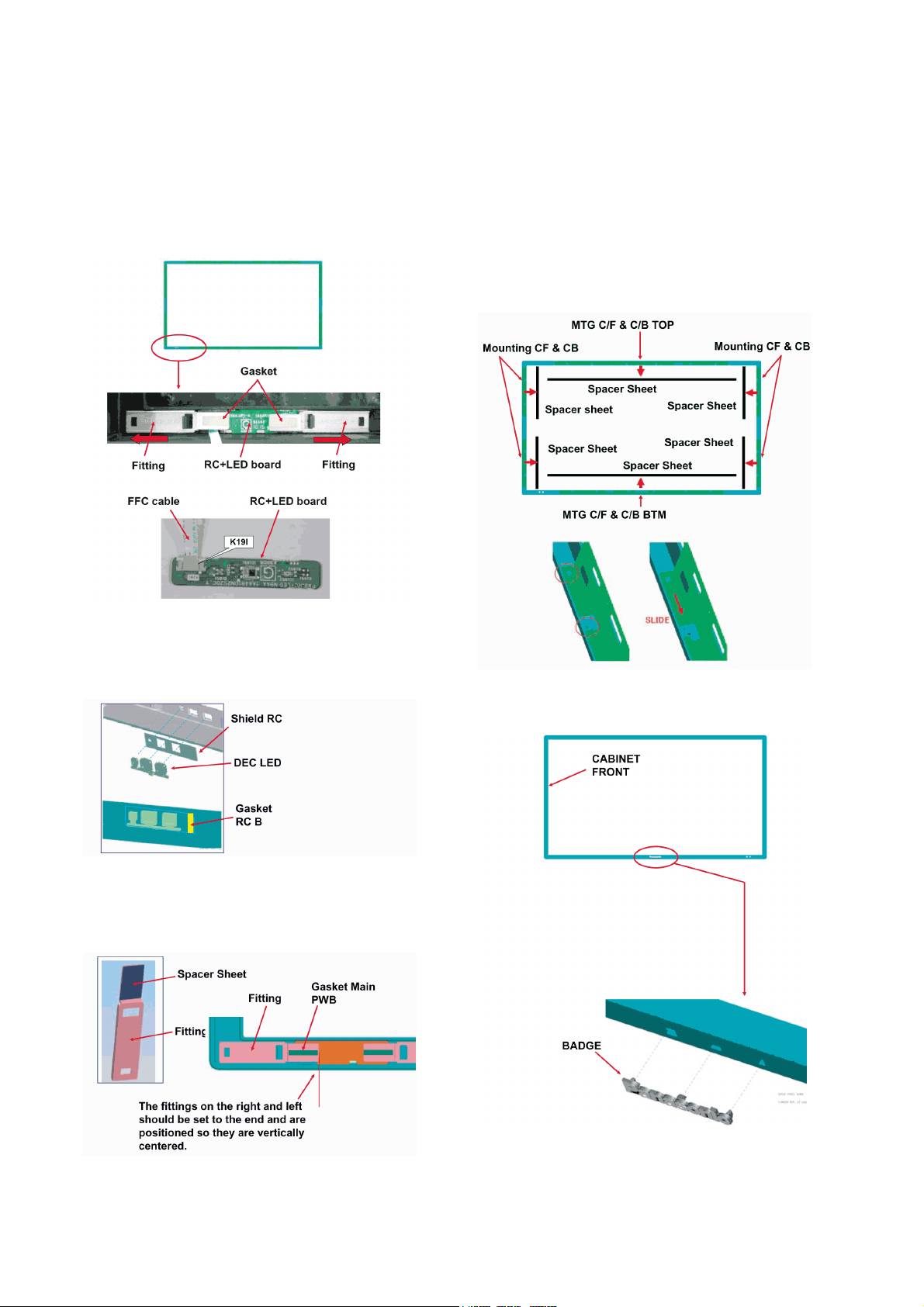
TH-42LF20E / TH-47LF20E
8.15. Replacement method for
RC+LED board
1. Slide the 2 fittings on the inside of the cabinet front toward
the outside and remove.
2. Remove the FFC cable from the RC+LED board's coupler
(K19I), and replace the board with the replacement
board.
8.16. Cabinet front replacement
Precautions when replacing
• The parts that are necessary for replacement (spacer sheet,
Panasonic badge, etc.) are not included. They are supplied
as replacement parts. Replace them at the same time as the
cabinet front.
1. Remove the spacer sheet that is affixed to the inside of
the cabinet front.
2. Slide off the mounting and remove it from the cabinet
front.
3. When replacing the cabinet front, remove the shield RC
and the DEC LED (clear plate) on the inside.
The gasket is affixed to the shield RC. When replacing,
also replace the gasket.
4. The spacer sheet and the gasket are affixed to the fittings
that hold down the RC+LED board.
When replacing the fittings, also replace the spacer sheet
and the gasket.
3. Affix the Panasonic badge to the replacement cabinet
front beforehand.
22
Page 23
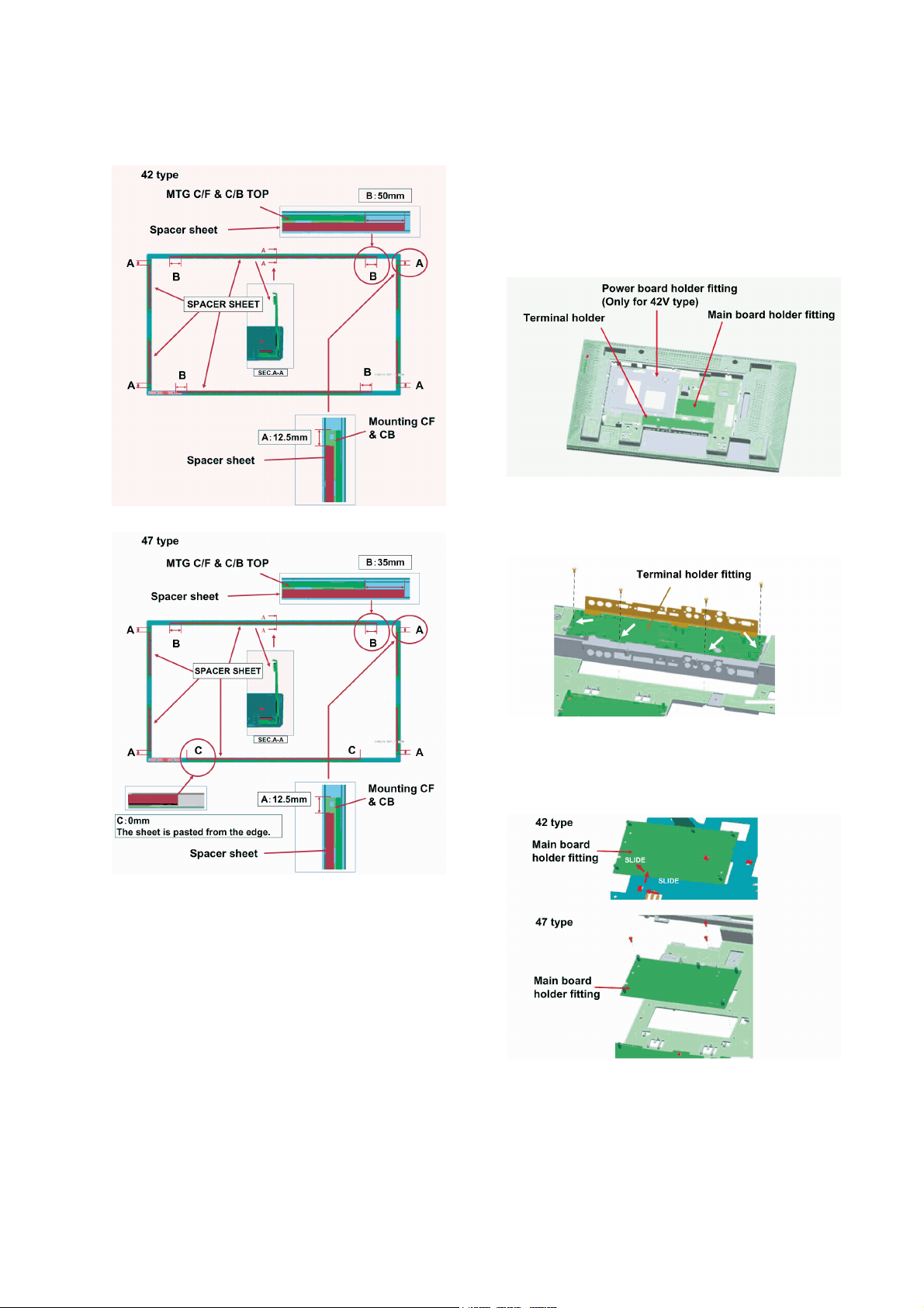
TH-42LF20E / TH-47LF20E
4. Install the RC+LED board onto the cabinet front.
5. Slide the mounting on and install it onto the cabinet front.
6. Affix the spacer sheet onto the mounting.
8.17. Cabinet back replacement
Precautions when replacing
• The parts that are necessary for replacement (DEC button,
DEC AV, etc.) are not included. They are supplied as
replacement parts. Replace them at the same time as the
cabinet back.
1. Remove each board, speaker and fitting from the cabinet
back.
2. Remove the screws (Qty. 4) shown in the illustration, and
remove the terminal holder fitting.
(SCR S-TPG BRZ+FLG 3.0X8.0 V)
7. Install the cabinet front, that is prepared beforehand, onto
the set.
3. Remove the screws shown in the diagram, and then
remove the main board holder fitting.
(42V type: Qty. 1 SCR S-TPG BRZ+FLG 3.0X8.0 V)
(47V type: Qty. 3 SCR S-TPG BRZ+FLG 3.0X8.0 V)
23
Page 24
TH-42LF20E / TH-47LF20E
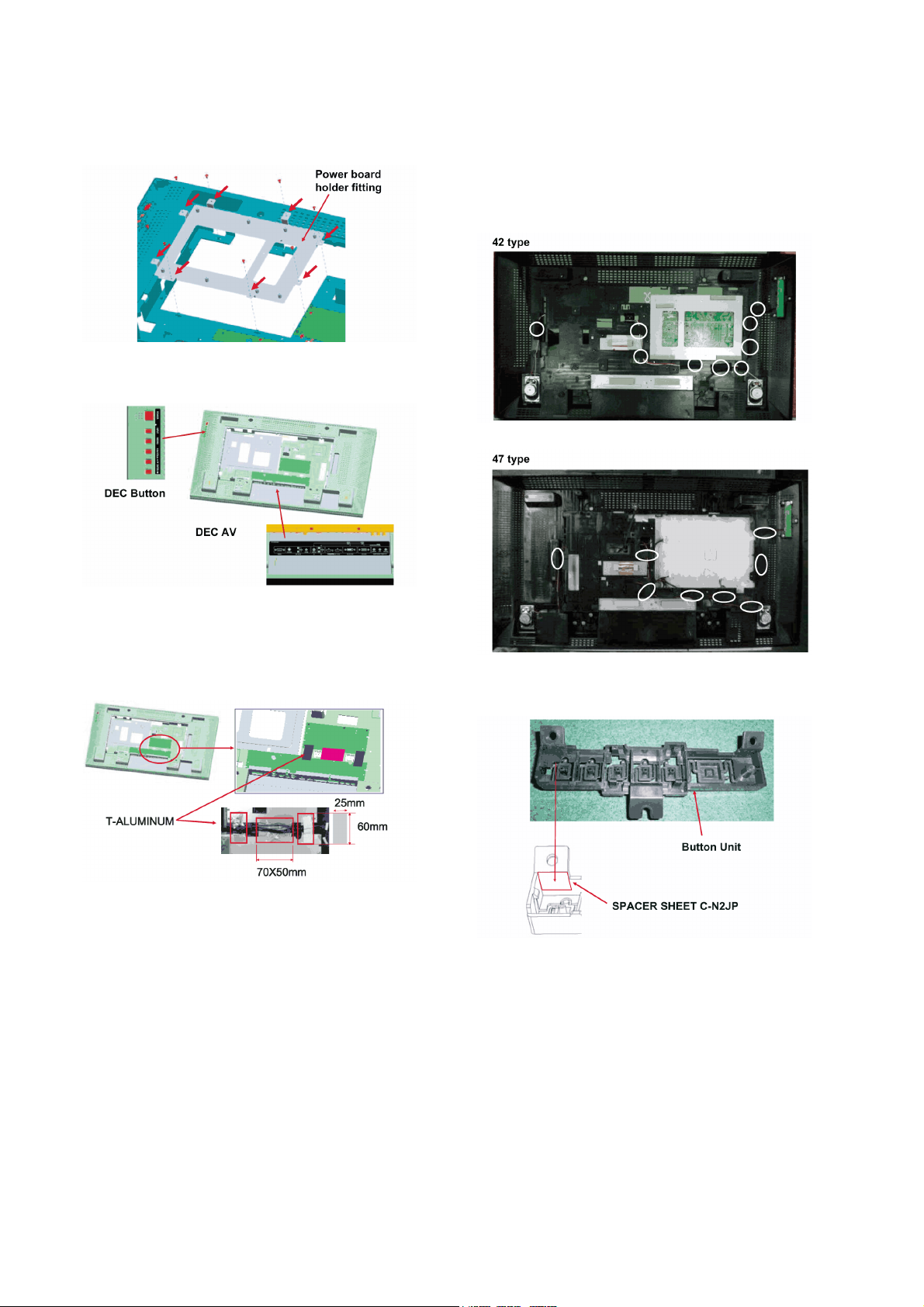
4. (42 type only) Remove the screws shown in the illustration, and then remove the Power board holder fitting.
(SCR S-TPG BRZ+FLG 3.0X8.0 V)
5. Affix the DEC button and DEC AV beforehand to the
repair cabinet back.
tape)
Caution
• Affix the tape so the lead wire is sealed tightly onto the
cabinet back. If the lead wire pops up, it may get close to
the board or a high temperature area and cause a chattering noise.
6. Install the main board holder fitting and the terminal
holder fitting to the replacement cabinet back.
7. Affix 3 pieces of aluminum tape to the metal section of the
main board holder fitting and the terminal holder fitting so
they are connected.
8. Install the replacement cabinet back, that is prepared
beforehand, onto the set.
Precautions for replacing
• The terminal holder fitting, the main board holder fitting,
and the Power board holder are available in the replacement parts.
• Use the gasket with the holder fitting that is affixed as is.
• The type of tape for affixing, in order to set up the lead
wire on the rear side of the cabinet back, is not included.
When replacing the cabinet back, also replace the type
of tape that is used.
When replacing the button unit that is installed onto the
key SW board, affix a spacer sheet onto the button unit.
When replacing the cabinet back, secure the lead wires
for the speaker and key SW board to the cabinet back
with replacement tape. The circle mark in the picture
below shows where to affix the tape. (Adhesive cloth
24
Page 25
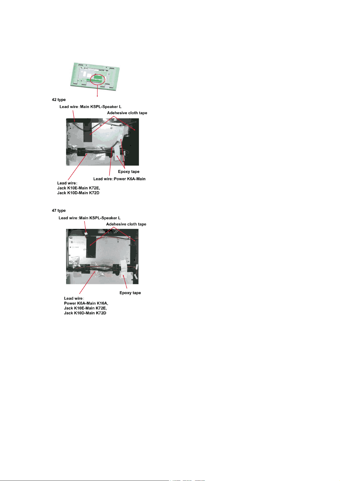
When replacing the cabinet back, secure the lead wires
for the speaker and main board to the cabinet back with
replacement tape.
TH-42LF20E / TH-47LF20E
25
Page 26

TH-42LF20E / TH-47LF20E
26
Page 27
9 Block Diagram
5VSTB
12VA
ON/OFF
24VP
IC1601
1
LUVP
2
3
CS/FB
4
GND
5
OUT6VCC
7
8
VSTR
D651
D652
D650
IC633
1
CSS
2
DELAY
3CF4
RFMIN
5
STBY
6
ISEN
7
LINE
8
DIS
9
PFC_STOP
10
GND11LVG
12
VCC
13
N.C.
14
OUT
15
HVG
16
VBOOT
T6011
COLDHOT
42 :T602
47 :T600
7
1
12
8
3
6
11
2
4
IC602
L605
12
1
5
6
7
8
10
11
9
24VP
24VP
I_PWN
KIV1
1
1
2
3
4
5
6
7
8
9
10
11
12
12
SEL
SEL
K6C
1
1
2
3
4
5
6
7
8
9
10
11
11
KIV2
1
1
2
3
4
5
6
7
8
9
10
11
12
13
14
14
BLON
BLON
I_PWN
12VA
E_PWN
E_PWN
MAIN-ON/OFF
MAIN-ON/OFF
F_5V
F_5V
F_5V
12VA
12VH
5VSTB
24VP
24VH
24VP
12VA
24VP
24VH
24VP
12VH
SWICH1
T652
2
1
5
4
7
8
9
10
3
42 :PC603
47 :D6809
SWICH
IC603
IC605
1
S/OCP
2
BR
3
GND
4
FB/OLP
5
VCC
7
D/ST
8
D/ST
Q604
D603
1
2
3
4
K601
1
4
RL601
SWICH1
SWICH
K6B
1
1
2
3
4
5
6
7
8
9
10
11
12
13
13
K16B
1
1
1
7
7
1
2
3
4
5
6
7
8
9
10
11
12
13
13
PWR-30V
DC416V
520V
400V
400/3A
MAX:AC264V/2.7A
400/3A
MAX:AC264V/2.7A
MAX:AC264V/2.7A
400V
200V
412V
NOISE
FILTER
Q613
Q612
Q614
Q615
Q6800
Q685
Q684
Q690~692
42 :Q6801
47 :Q600,Q601,Q605,Q606
Q1606
Q1601
Q602
Q604
1
1
2
3
4
5
6
7
8
9
10
11
11
BLON
L6603
P_FAIL1
P_FAIL1
K16C
P_FAIL1
P_FAIL1
DCR_VBR
BLON
DCR_VBR
12V_PWR
5VSTB
24V
L6604
5VSTB
L6605
12V/24V_EN
Q6620
Q6621
K6A
1
2
3
4
5
6
7
SWICH1
MAIN_EN
SWICH
SWICH2
K16A
1
2
3
4
5
6
7
MCU_5V
12VPAN_EN
12VPAN_EN
PANEL_12V
IC6600
2
3
7
12V
IC7504
1
2
3
4
1.2VSTB
3.3VSTB
IC7501
1
2
3
4
1.2V_AUD
5VSTB
3.3V_I/O
3.3V_AUD
3.3V_LVDS
Q7501
IC7505
1
2
3
4
3.3V_LBADC
3.3V_ADC
3.3V_HDMI
Q7502
1
2
3
45
6
7
8
3.3V
5VD_PWR
IC7503
1
2
3
4
1.2V
1.8V_DDR
IC5503
1
2
3
4
5
6
7
8
9
IC7506
1
2
3
4
0.9_DDR_VREF
1.2V_DPRX
1.8V_DDR
1.2V_ADC
3.3V_DDR
1.2V_HDMI
1.2V
1.2V_CORE
3.3V
3.3V_SW
IC6612
123
45
678
9
PWM1
DCR_VBR
DCR_IN
OPC_EN
OPC_EN
KLVP
PANEL_12V
3.3V_I/O
3.3V_I/O
PEL-TEST
PEL-TEST
LCD PANEL
Q4001
MAIN CHIP
IC7200
(NEXT PAGE)
SWICH1
MAIN_EN
SWICH
SWICH2
MAIN BOARD
POWER BOARD
(42 ONLY)
Q607
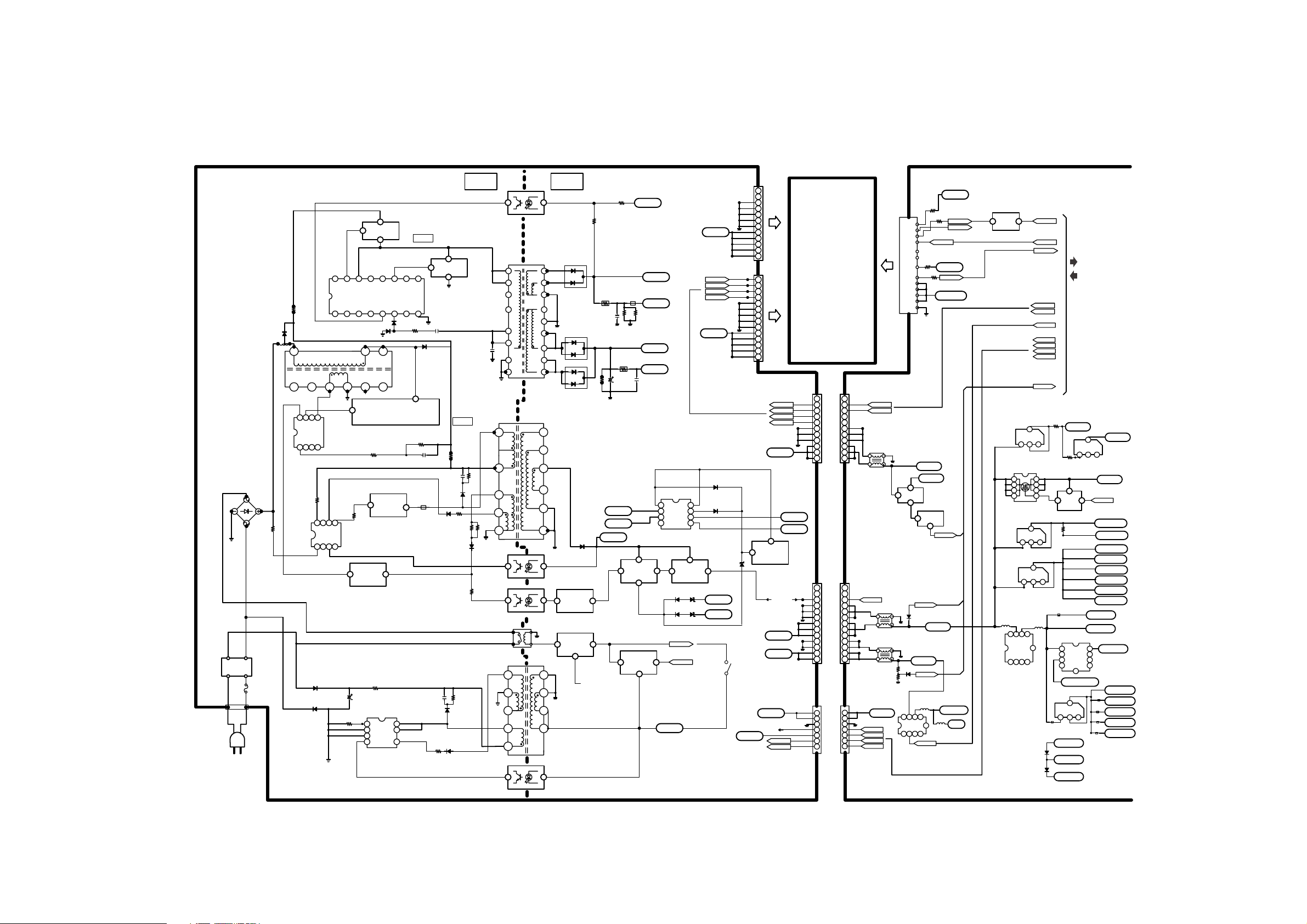
9.1. Block (1 of 2) Diagram
TH-42LF20E / TH-47LF20E
27
Page 28
TH-42LF20E / TH-47LF20E
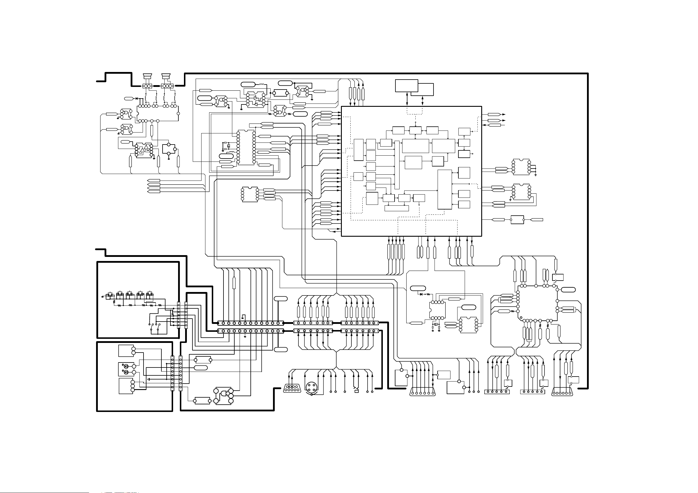
9.2. Block (2 of 2) Diagram
12V_PWR
IC2009
MUTE
IC2010
AMP_STBY
IC8134
12V
OUT_R
TO POWER BOARD
FROM CONNECTOR BORD K16A
SP-LSP-R
PC_DET
IR
TX
RX
DRXD
DTXD
5VSTB
Q7206
IC2006
KEY_POWER
LED_GREEN
UART-SW
RXD1
3.3VSTB
IC2005
TXD1
AV1_Y
AV1_C
AV1_S
AV3_CVBS+
KEY 0
LED_RED
LIGHT_DET
AV_IN_L
AV_IN_R
PC_R
PC_L
DVI_IN_L
DVI_IN_R
AV2_Y/G
AV2_PB/R
AV2_PR/B
VGA_G/Y
VGA_R/PB
VGA_B/PR
H_SINC
V_SINC
VGA_IIC
TXD0
RXD1
UART-SW
Cross
Point
Switch
MUX
TXD1
Main Chip
IC7200
Triple
10-bit
ADC 1
Triple
10-bit
ADC 2
Digital
Input
DVI \
HDMI
Display
Port Rx
ADC
inputs,
I2S\
SPDIF Rx
3D Video
Decoder
Audio
Mux
VBI Data
Processor
I2S SPDIF Tx
IC5500
Audio
DSP
MCU_5V
IC2007
MCU_5V
RXD0
RTC
IC2008
SUB MCU
IC7201
10
IC2003
SYNC_DET
20
19
18
17
16
15
14
5VD_PWR
13
12
11
SWICH
KSPLKSPR
R+
43
PVD144PVD1
MUTE
STBY
VIN1+
L-
L+
R-
PLC
25
OUT2+26OUT2+30OUT2-31OUT2-36OUT1-37OUT1-41OUT1+42OUT1+
VIN2+
45
RXD0
MCU_5V
TXD0
AUDIO AMP.
IC001
SPEAK_SW_R
Q615
MAIN_EN
SWICH2
SWICH1
SWICH
OUT_L
SWH-SPEK
RS-232C SW
DDR SDRAM
IC5501
Memory
OSD
Controller
Controller
DCDi, Motion Adaptive
De-interlacing, Scaling,
Shaping Filter,
2nd Channel
Processing +
DCDi EdgeTM
Audio
DAC
Enhancer, ACC II,
ACM-3D, 3x3 Matrix,
PicBlend, CLUTs,
OSD Blend
3x3 Matrix
Embedded
Microprocessor
I2C BUS
LVDS Tx
Output
Formatter
Display
Port Tx
General
Purpose
I \ O
SPI Interface
ADC
IR I/F
MAIN BOARD
PWM1
TO LCD PANEL
OPC_EN
PEL-TEST
FROM CONNECTOR BOARD(KLVP)
EEPROM
MSTR1_SCL
MSTR1_SDA
SPI Serial
SPI_CEN
SPI_DI
SPI_DO
SPI_CLK
FAIL P_FAIL 1
IC8001
IC8000
Q7207
Q7208
KEY SW BOARD
ENTER
POS+
POS-
MENU
INPUT
SW1906
SW1902SW1903SW1904SW1905
K19G
SW1901
MCU5V
IC1951
IR
GREEN
RED
IC1952
D1951
IOUT
VCC
GREEN
3.3STB
BACKLIGHT
RED
GND
K19I
IR
5V
K39H
RC+LED BOARD
K39G
Q1902
3.3VSTB
Q1901
KEY0
K19F
IC2012
LIGHT_DET
BACKLIGHT
KEY-POWER
5VD
3.3VSTB
RED
GREEN
IR
3.3STB
SWICH2(F-5V)
SWICH1
AV1_C
K72E K72D
K10E K10D
AV1_C
3.3VSTB
JACK BOARD
RX
TX
RS232C
IN
AV1_Y
AV1_C
AV1_Y
Y / C
DVI_IN_L
DVI_IN_L
DVI_IN_R
AV1_Y
IN
TX
DVI_IN_R
TX
AV1_S
RX
RX
DVI_IN_R
DVI
L / R
IN
DVI_IN_L
AV3
CVBS
PC_L
PC_R
PC_R
PC_L
PC_L
AV3_CVBS+
L / R
IN
AV3_CVBS+
AV3_CVBS+
AV_IN_L
PC_R
PC
IN
AV_IN_L
AV_IN_R
AV_IN_R
L / R
AV_IN_R
AV
IN
AV1_S
AV1_S
AV_IN_L
MUTE
OUT_R
AMP_STBY
PC_DET
Q1501
Q1502
Q1503
OUT_L
SWH-SPEK
MCU_5V
IC804
RTC
REAL TIME CLOCK
VGA_R/PB
VGA_G/Y
SDA
SCL
H_SINC
VGA_B/PR
PC IN
RTC
V_SINC
CLOCKOUT
IIC
EEPROM
IC1501
VGA_IIC
POW_SINK
HDMI_SDA
CLOCKOUT
SCL
SDA
SYNC_DET
Q2001
Q2003
HDMI_SCL
HDMI1_DATA_CLOCK
3.3VSTB
IC805
HDMI_HPD
AV2_Y/G
AV2_PB/R
AV2
IN
HDMI/DVI-D SW
IC750
HDMI1_HPD
HDMI1_SDA
HDMI1_SCL
HDMI1_DATA_CLOCK
HD5V1
HD5V1
Q310
HDMI1_CEC
+5V
HDMI1_IIC
HDMI1_DATA_CLOCK
AV2_PR/B
HDMI 1
IN
POW_SINK
HDMI1_HPD
HDMI_SDA
HDMI_SCL
HDMI2_HPD
HDMI2_SDA
HDMI2_IIC
HDMI2_DATA_CLOCK
HDMI 2
HDMI1_DATA_CLOCK
IIC
HDMI2_SCL
HDMI2_DATA_CLOCK
HD5V2
HDMI2_CEC
+5V
IN
SCL
HD5V2
HDMI2_HPD
Q311
SDA
HD5V3
TMDS_DATA_CLOCK
HDMI_HPD
Q701
3.3VSTB
TMDS_DATA_CLOCK
DVI_SCL
DVI_SDA
HOT_PLUG
HD5V3
+5V
DVI_IIC
DVI-D
HOT_PLUG
Q309
28
Page 29
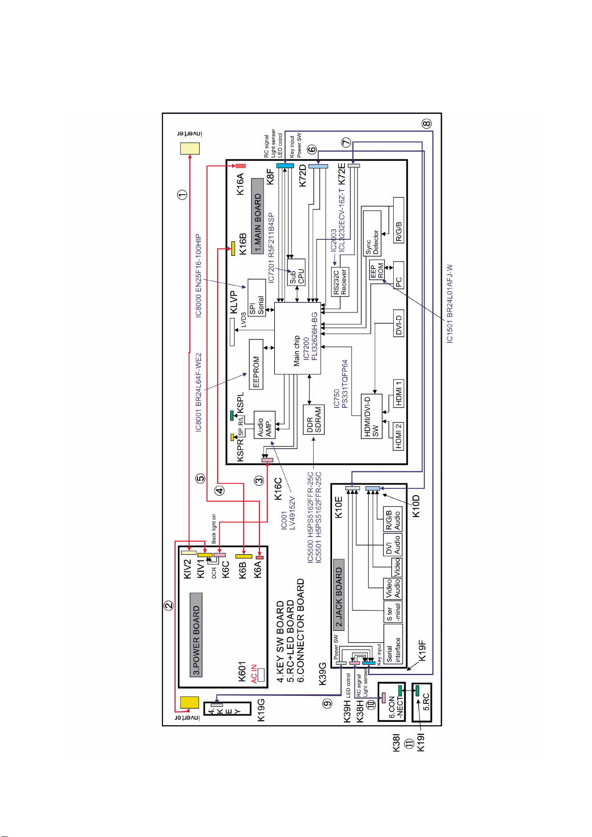
10 Wiring Connection Diagram
10.1. Wiring Connection Diagram (1)
TH-42LF20E / TH-47LF20E
29
Page 30
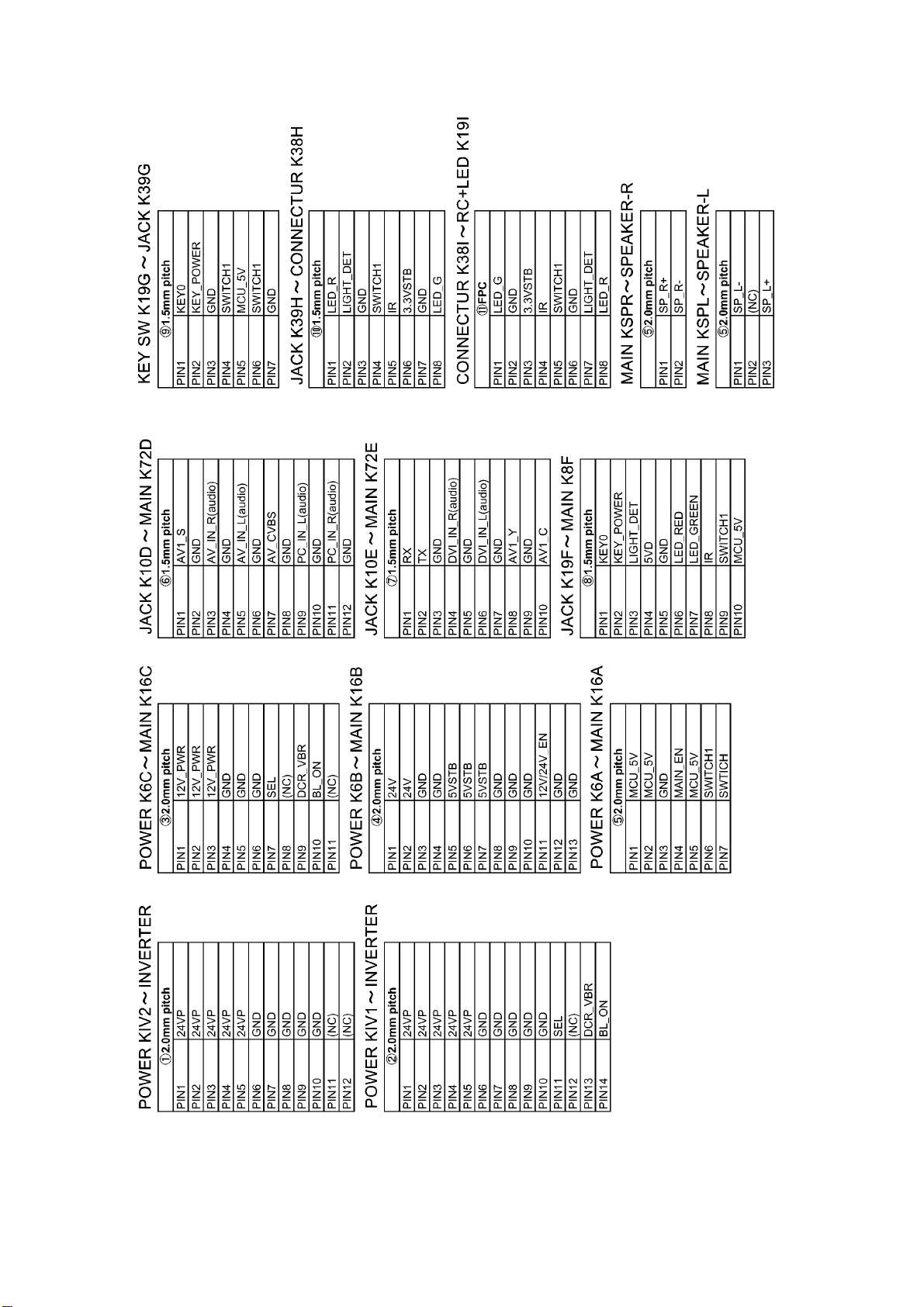
TH-42LF20E / TH-47LF20E
30
Page 31
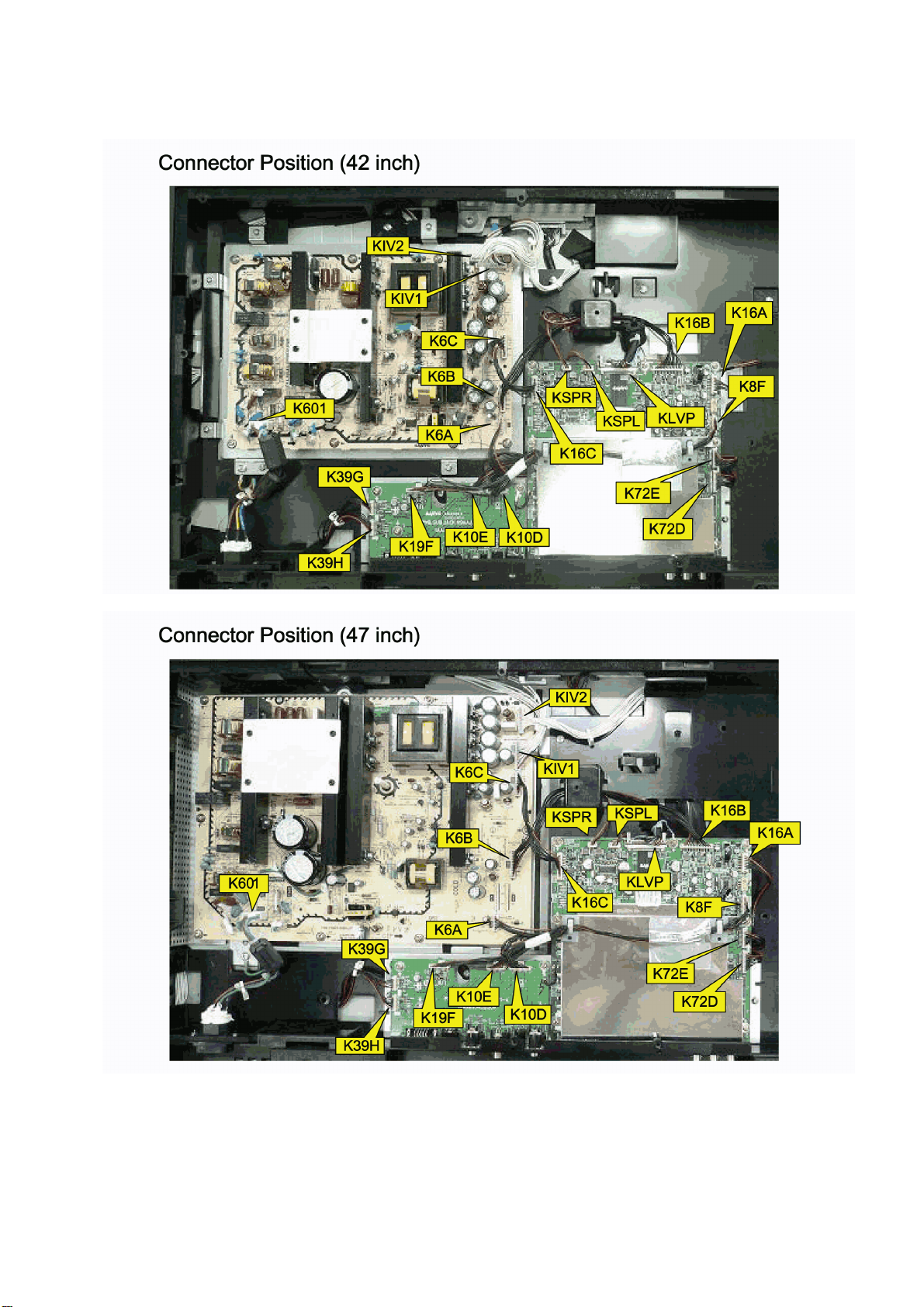
10.2. Wiring Connection Diagram (2)
TH-42LF20E / TH-47LF20E
31
Page 32
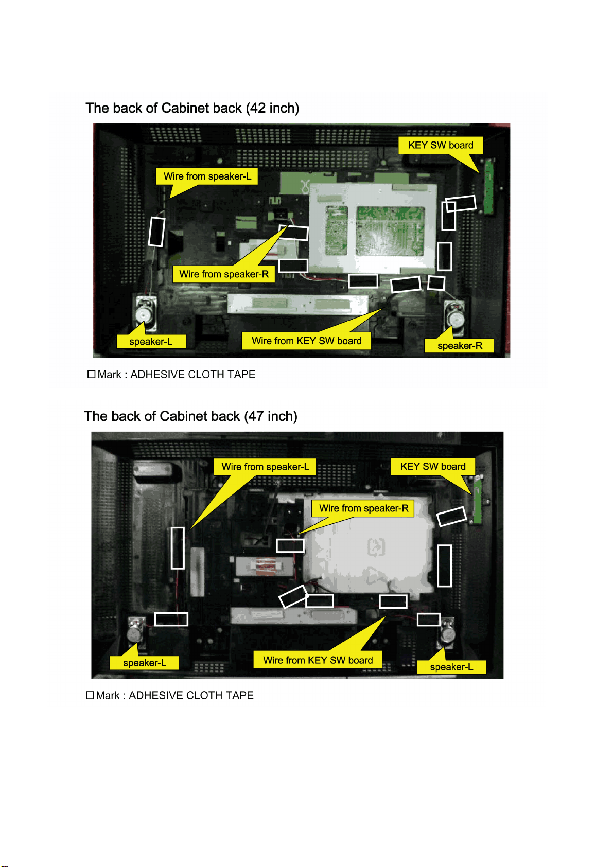
TH-42LF20E / TH-47LF20E
10.3. Wiring Connection Diagram (3)
32
Page 33
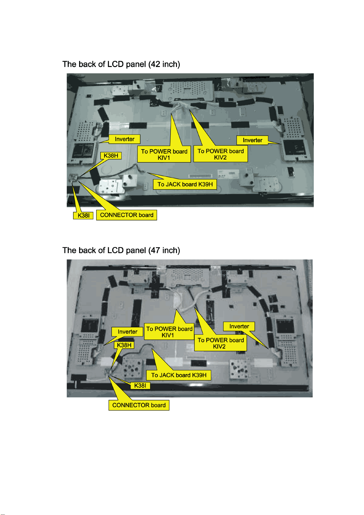
10.4. Wiring Connection Diagram (4)
TH-42LF20E / TH-47LF20E
33
Page 34
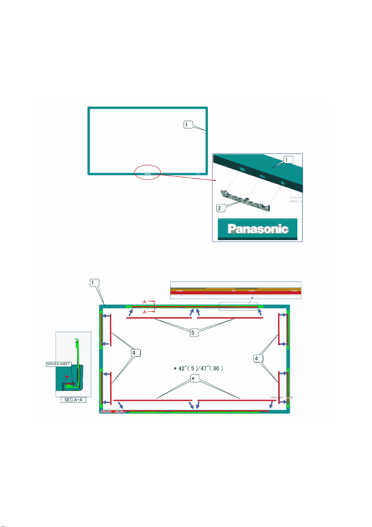
TH-42LF20E / TH-47LF20E
11 Exploded View and Replacement Parts List
11.1. Exploded View and Mechanical Replacement Parts List
11.1.1. Exploded View
11.1.1.1. Cabinet front (1)
34
Page 35
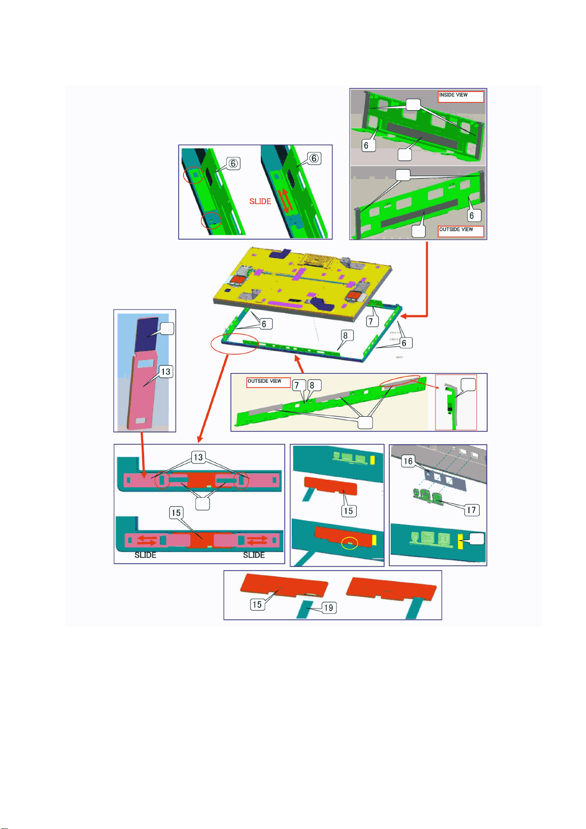
11.1.1.2. Cabinet front (2)
TH-42LF20E / TH-47LF20E
35
Page 36
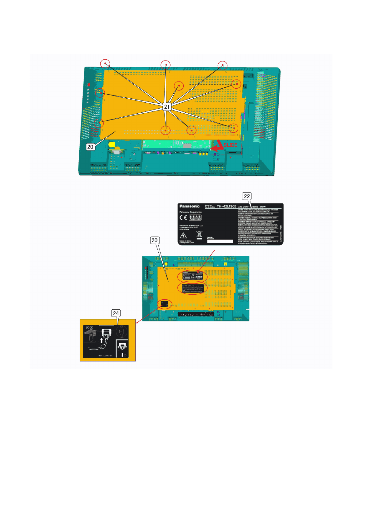
TH-42LF20E / TH-47LF20E
11.1.1.3. Lid back
36
Page 37
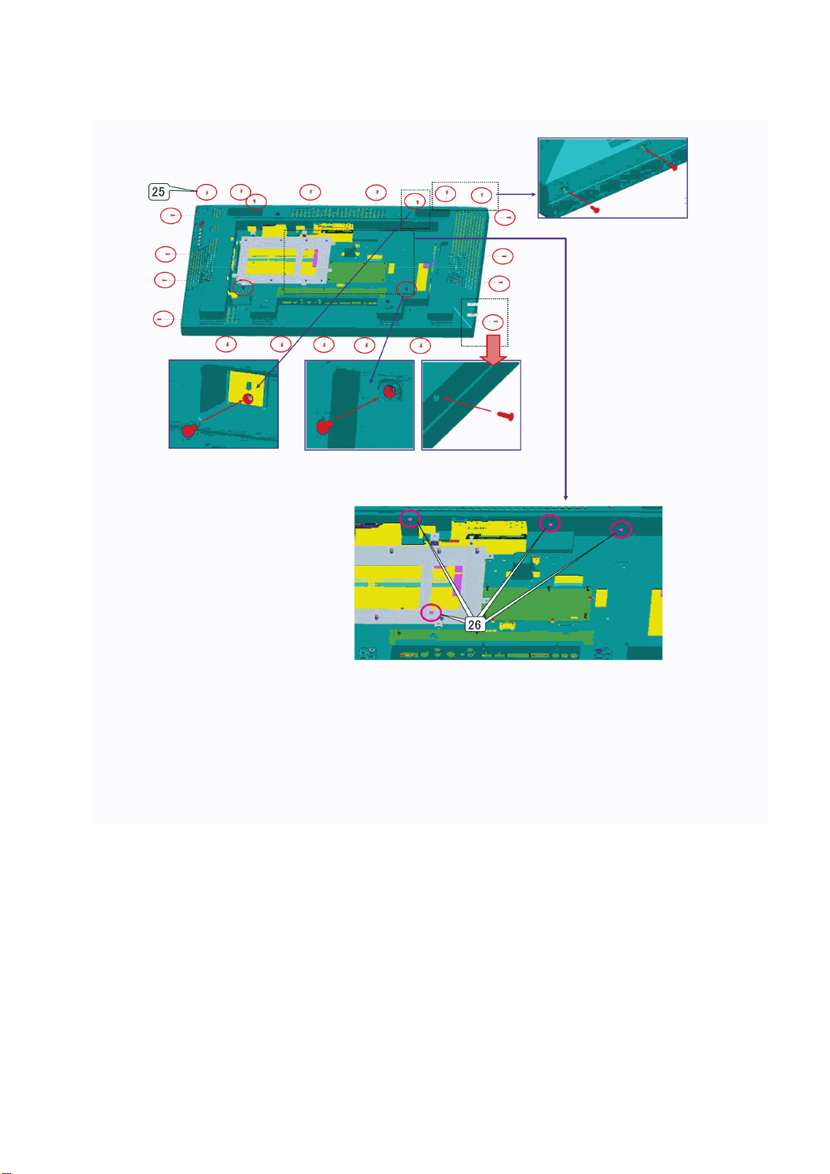
11.1.1.4. Screws for Cabinet back (42”)
TH-42LF20E / TH-47LF20E
37
Page 38
TH-42LF20E / TH-47LF20E
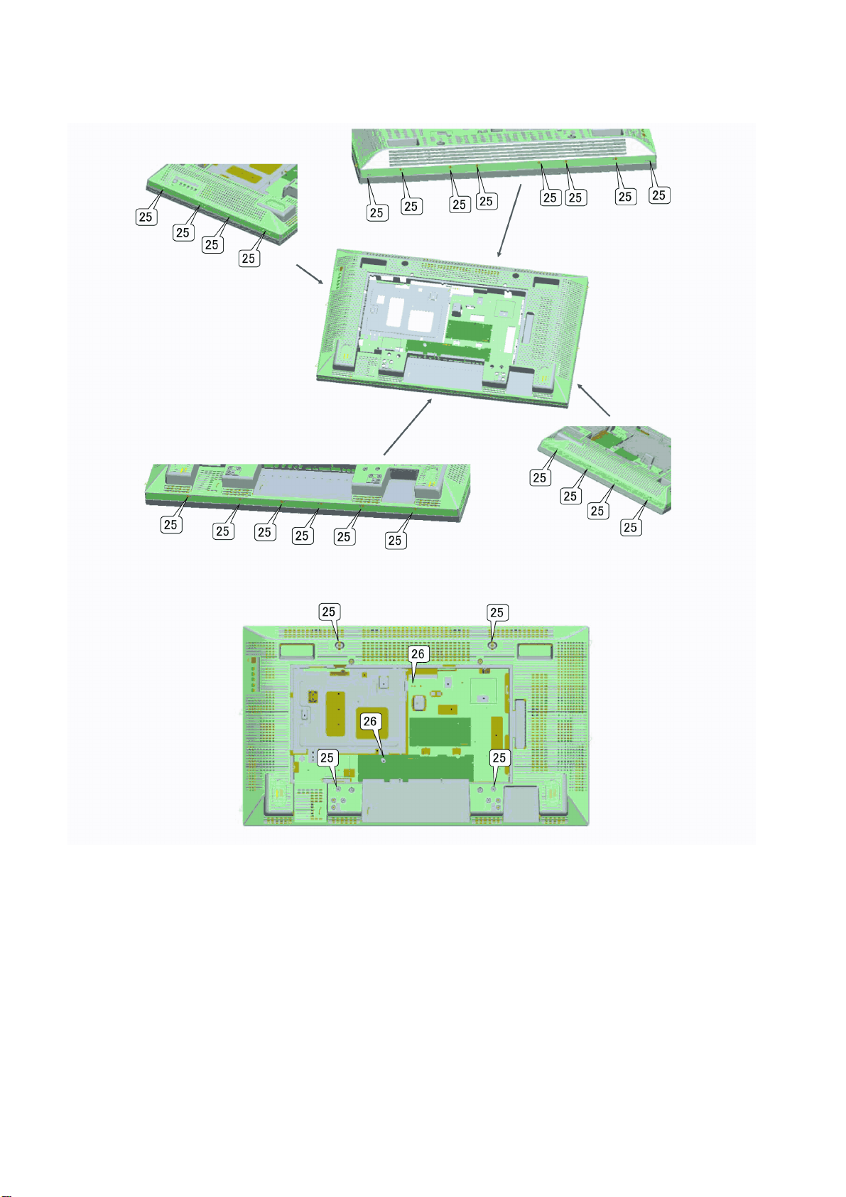
11.1.1.5. Screws for Cabinet back (47”)
38
Page 39
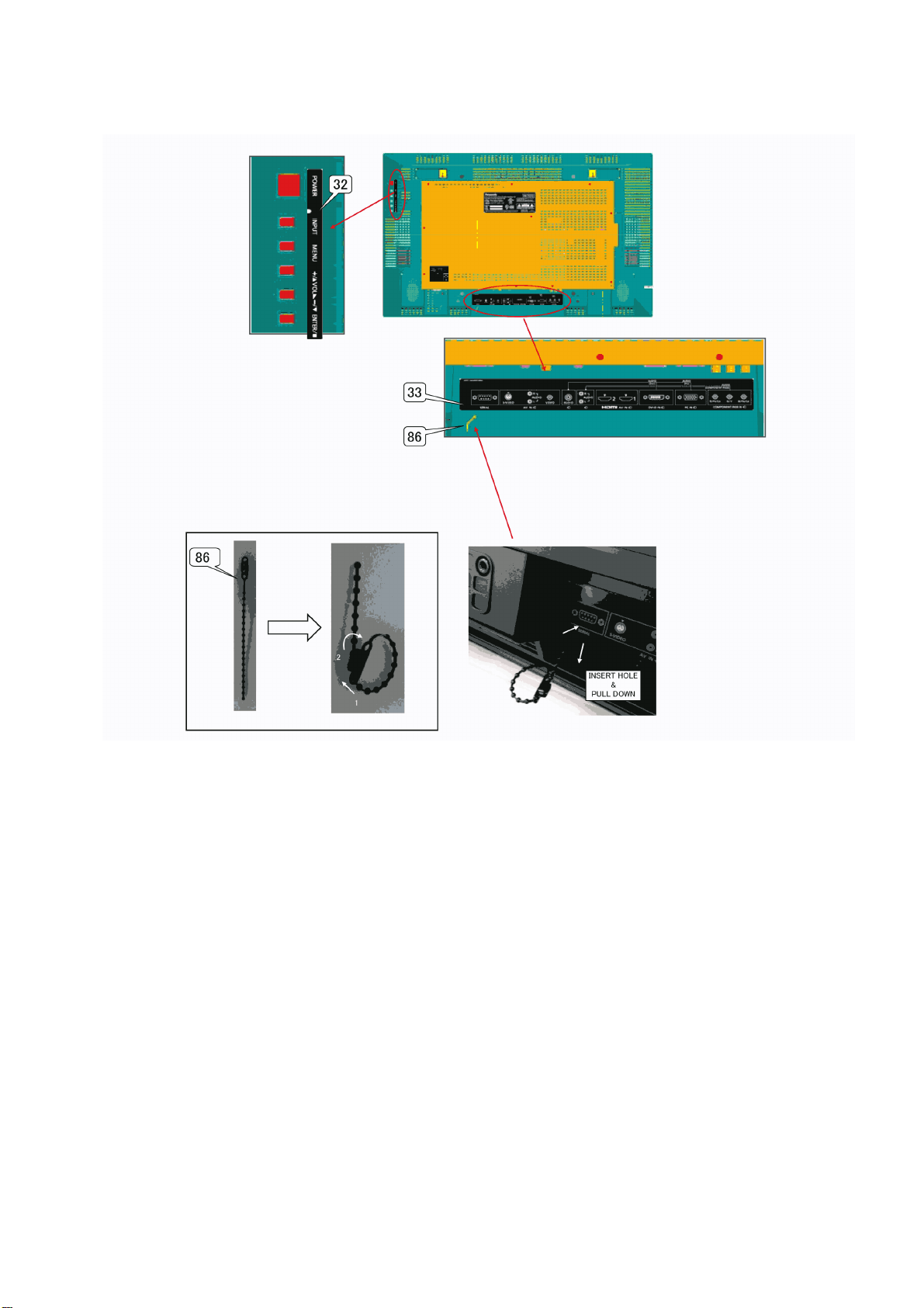
11.1.1.6. Cabinet back (42”)
TH-42LF20E / TH-47LF20E
39
Page 40
TH-42LF20E / TH-47LF20E
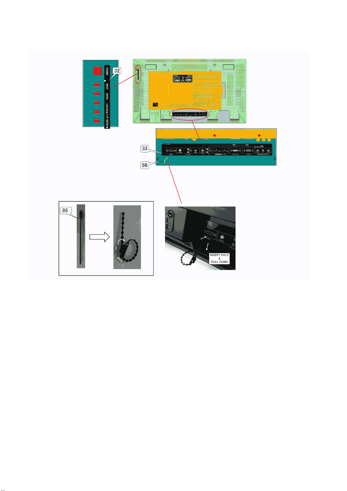
11.1.1.7. Cabinet back (47”)
40
Page 41
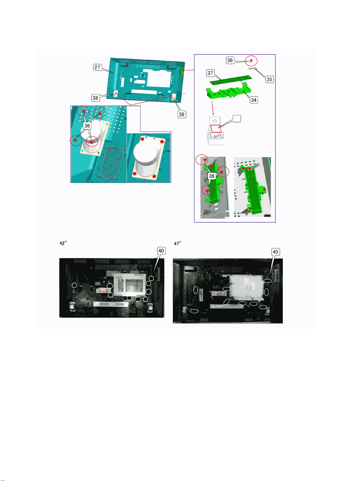
11.1.1.8. Inside of Cabinet back
TH-42LF20E / TH-47LF20E
41
Page 42
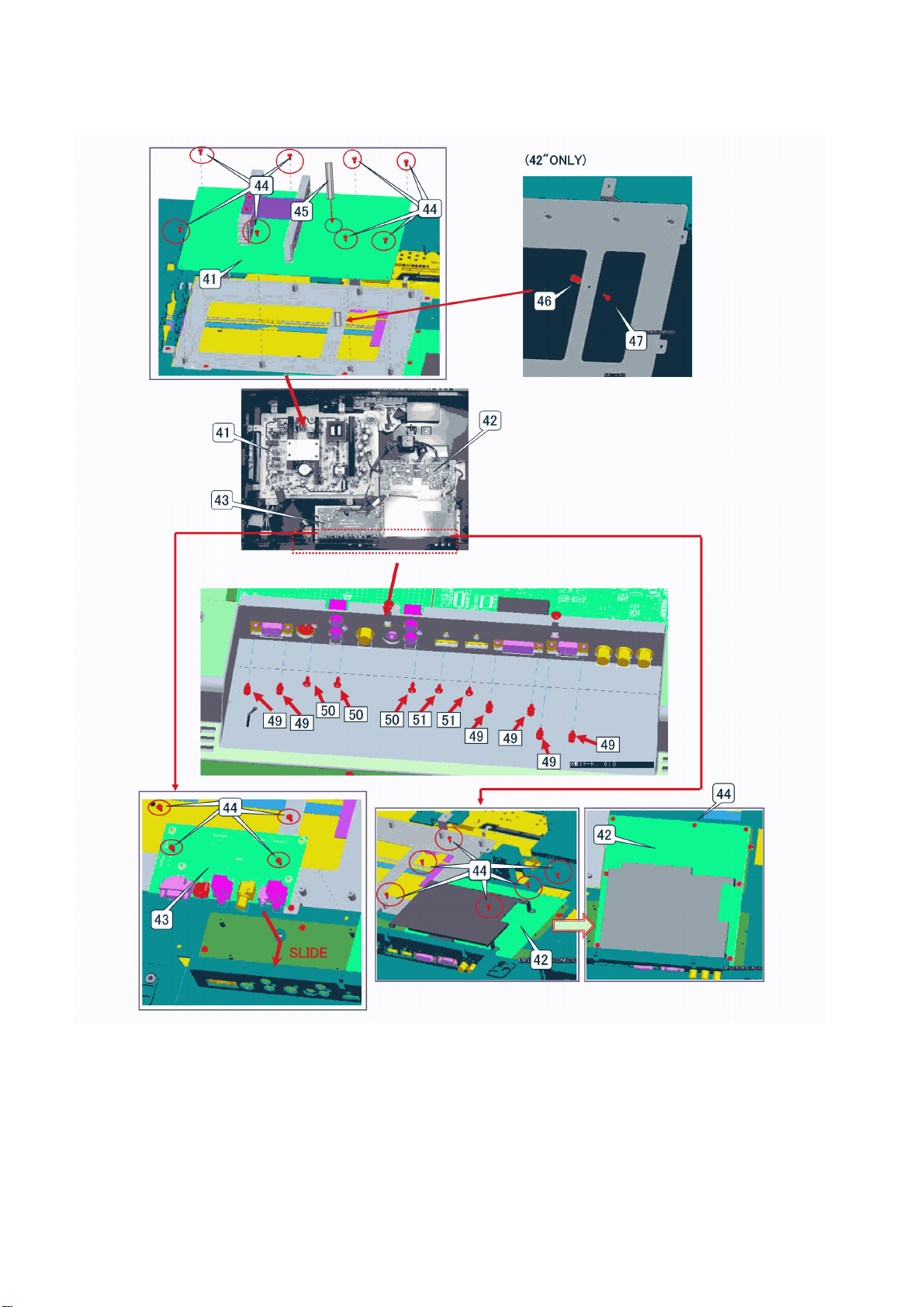
TH-42LF20E / TH-47LF20E
11.1.1.9. Screws for board (42”)
42
Page 43
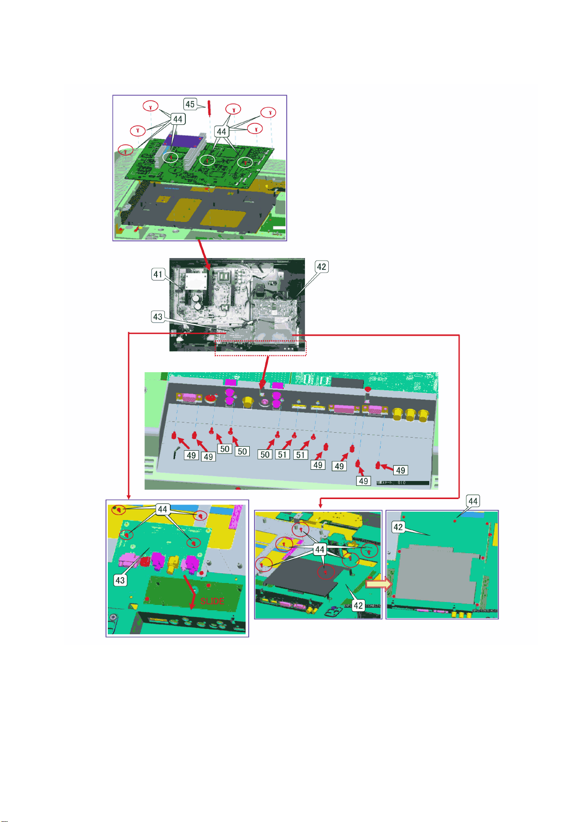
11.1.1.10. Screws for board (47”)
TH-42LF20E / TH-47LF20E
43
Page 44
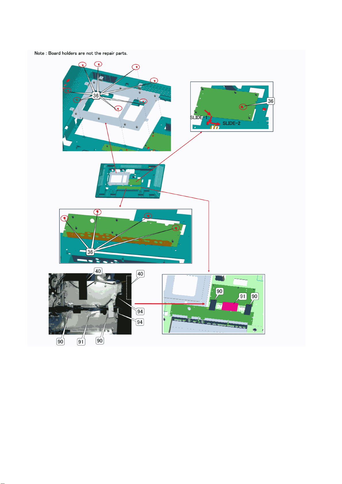
TH-42LF20E / TH-47LF20E
11.1.1.11. Screws for board holder (42”)
44
Page 45
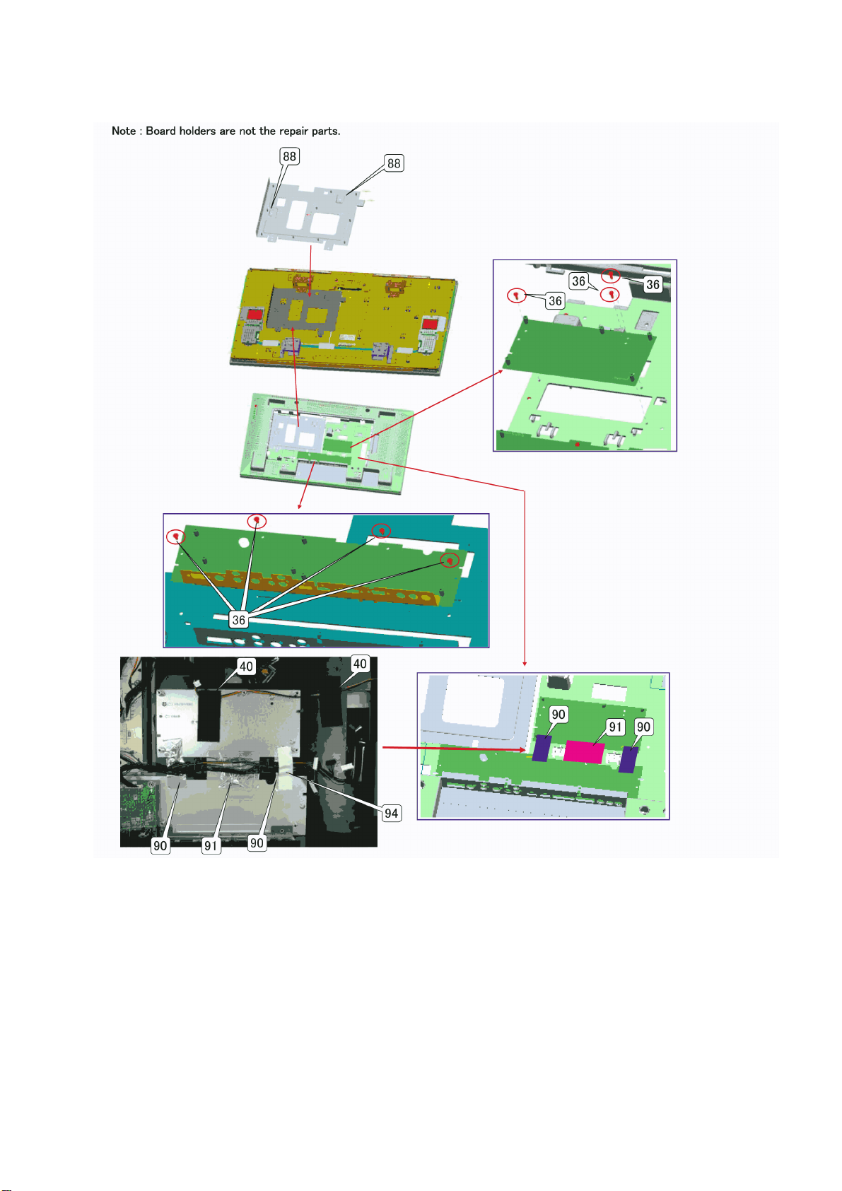
11.1.1.12. Screws for board holder (47”)
TH-42LF20E / TH-47LF20E
45
Page 46
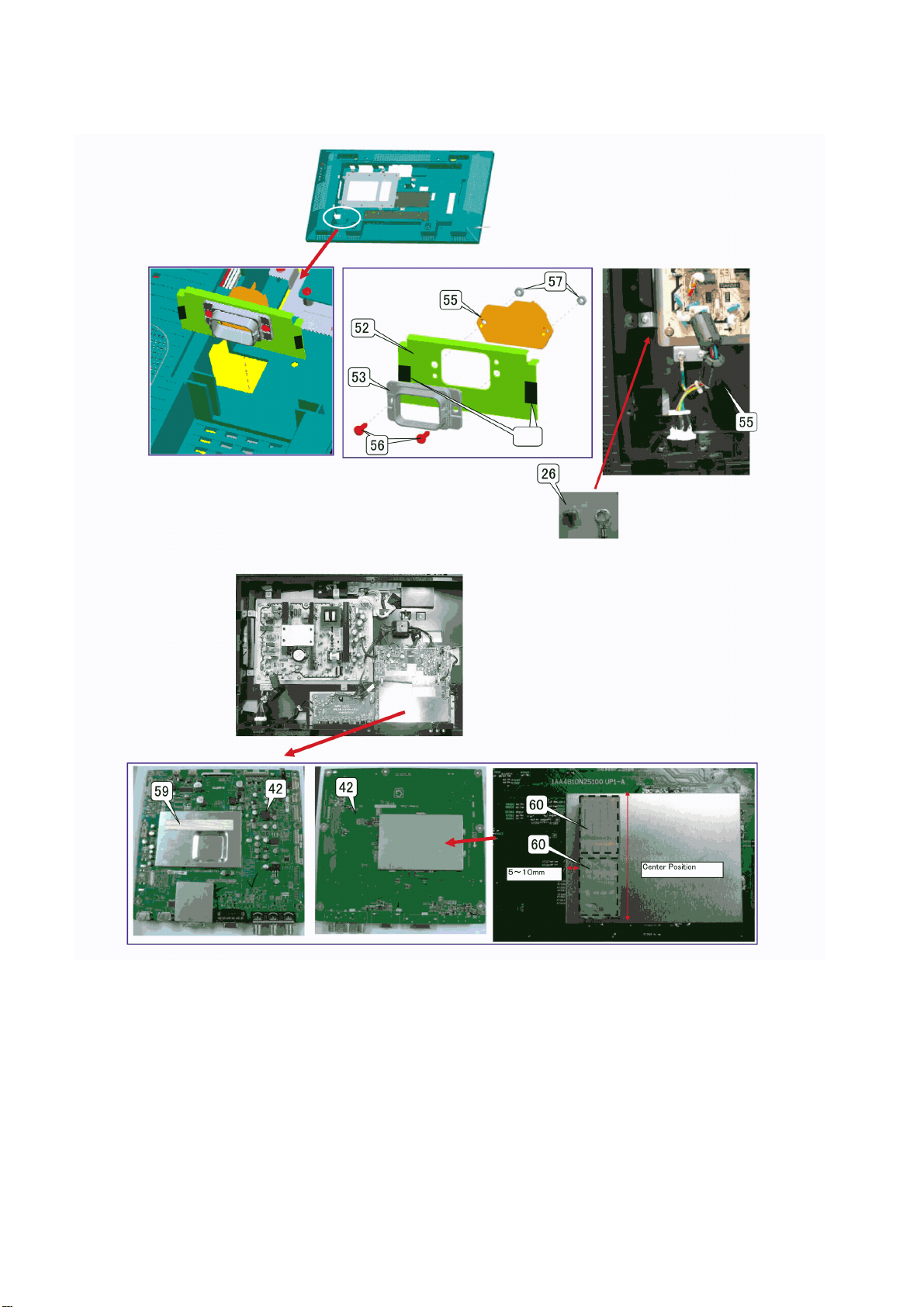
TH-42LF20E / TH-47LF20E
11.1.1.13. Gasket around the AC inlet and Main board
46
Page 47
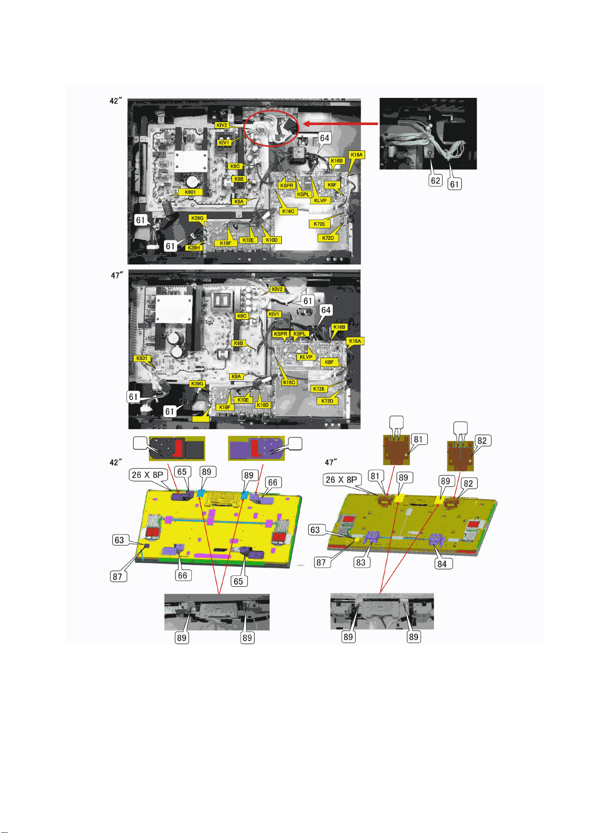
11.1.1.14. Wire, Panel mounting bracket
TH-42LF20E / TH-47LF20E
47
Page 48
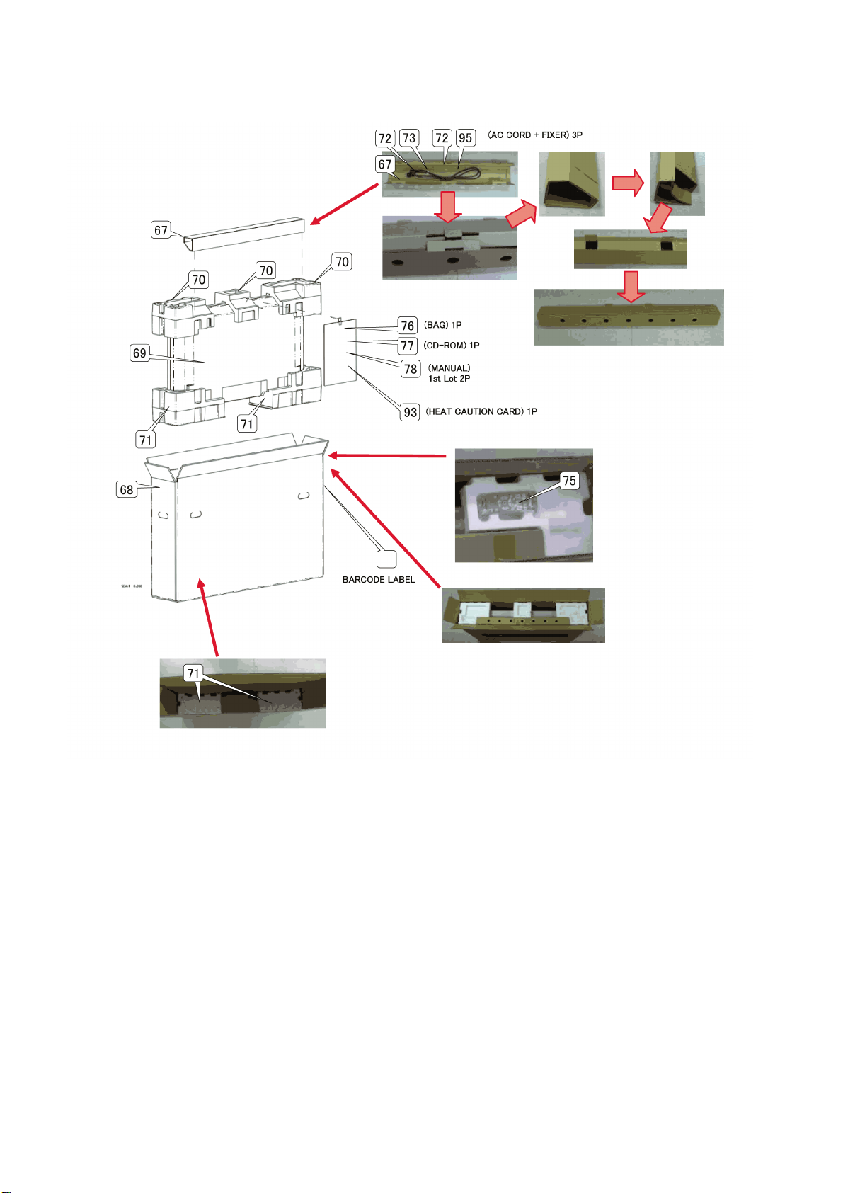
TH-42LF20E / TH-47LF20E
11.1.1.15. Packing, Accessories (42”)
48
Page 49
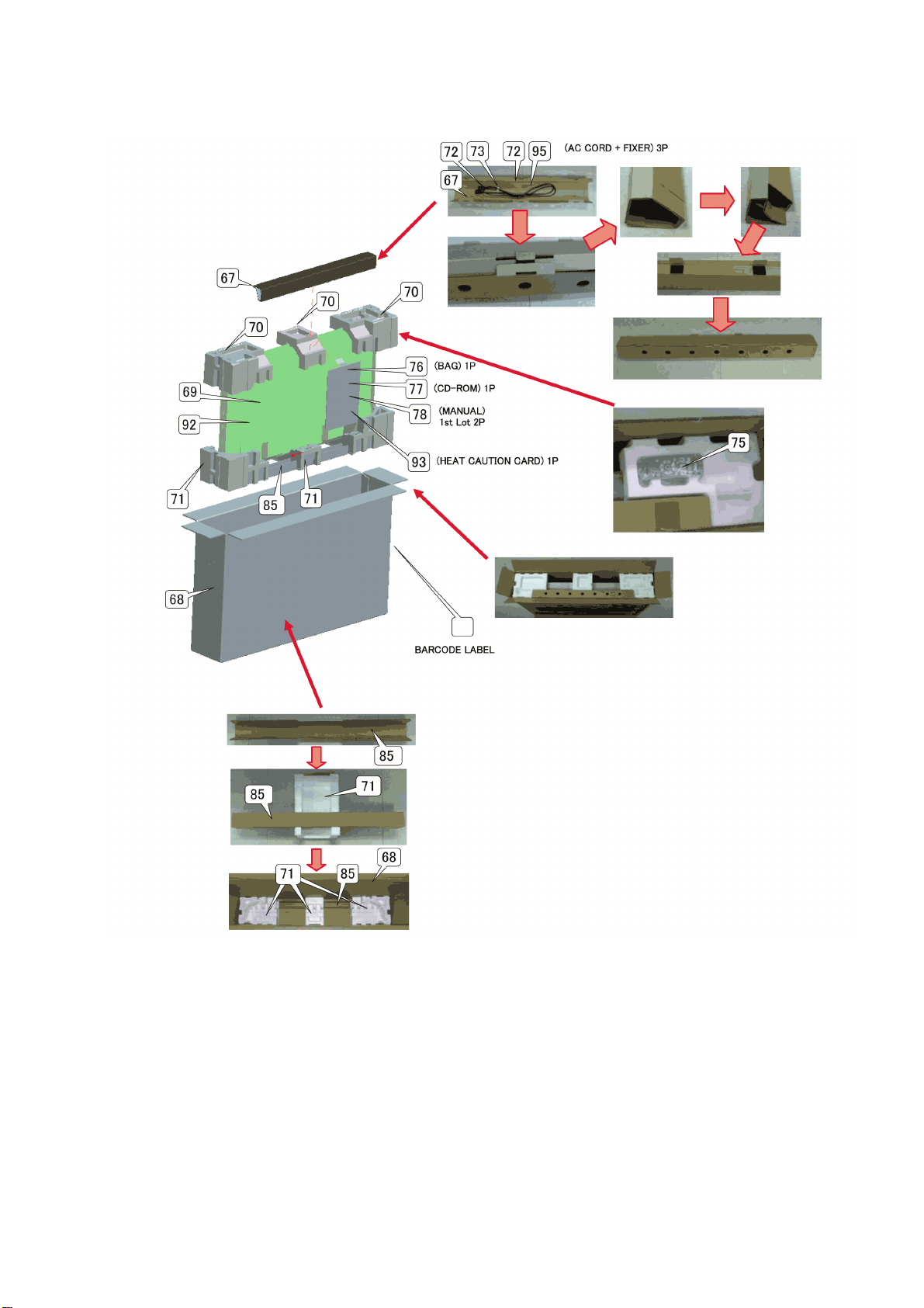
11.1.1.16. Packing, Accessories (47”)
TH-42LF20E / TH-47LF20E
49
Page 50
TH-42LF20E / TH-47LF20E
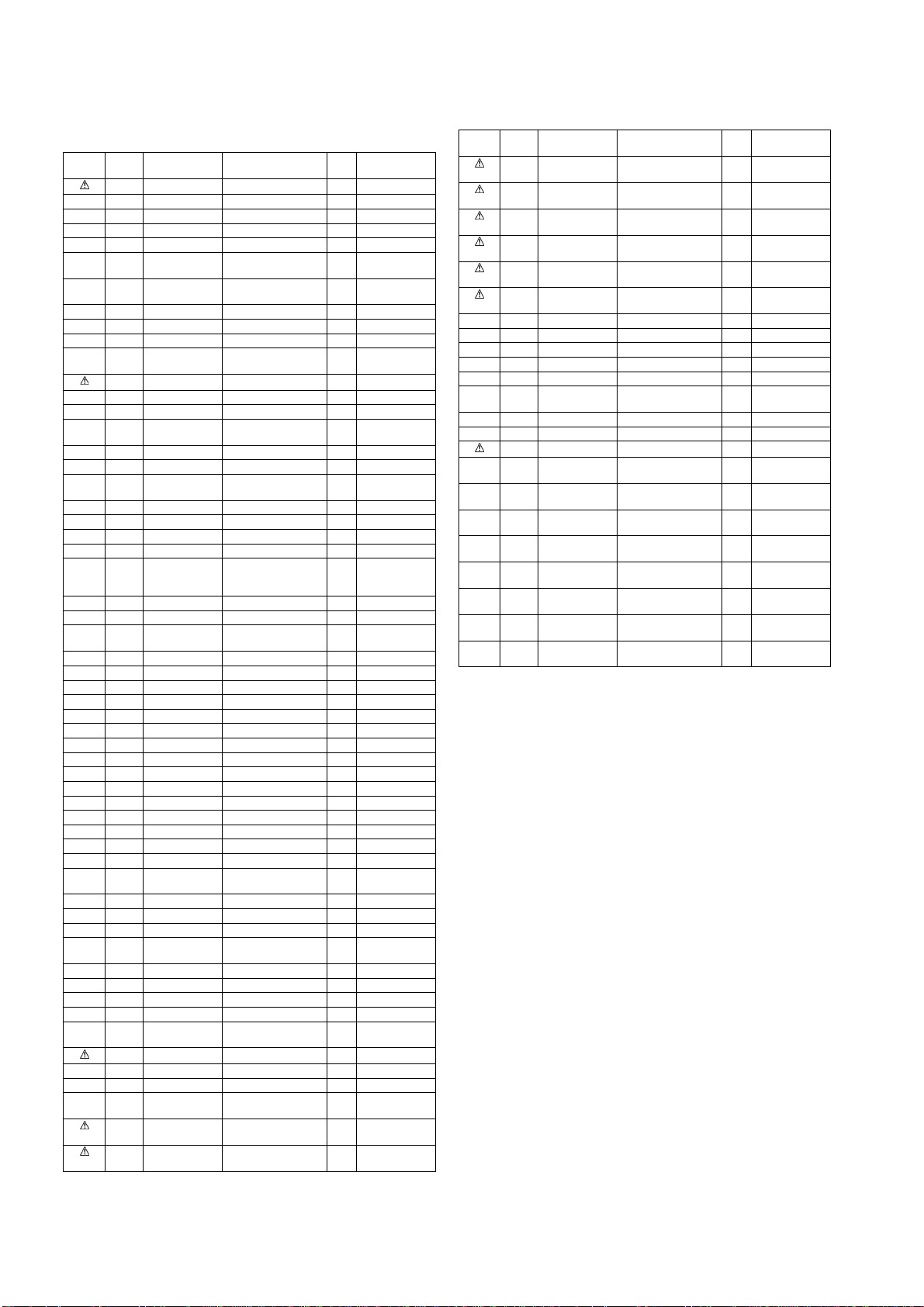
11.2. Mechanical Replacement Parts List (42 inch)
Safety Ref.
1 T6103511795 CABINET FRONT 1
2 TBMA162 PANASONIC BADGE 1
4 T6103528212 SPACE SHEET 4
5 T6550038838 SPACER SHEET 4
6 TZ6103504162 MOUNTING CF & CB 4
7 TZ6103506708 MTG C/F & C/B
8 TZ6103506715 MTG C/F & C/B
13 TZ6103504285 MOUNTING DEC 2
16 TZ6103529578 SHIELD RC 1
17 T6103504179 DEC LED 1
19 T6451037602 FLEXIBLE FLAT
20 T6103511887 LID BACK 1
21 T4112062406 SCR TPG BRZ 4X10 10
22 T6103510521 LABEL RATING 1
24 T6103504407 LABEL FOR AC
25 T4112168603 SCR FLT 4X12 23
26 T4111899003 SCR BIN 4X6 13
27 T6103534558 BACK CABINET
32 T6103531052 DEC BUTTON 1
33 T6103504421 DEC AV ENGLISH 1
34 TZ6103511917 BUTTON UNIT 1
35 T6103450971 EARTH LVDS 1
36 T4111926402 SCR S-TPG
38 T6520033436 L-SPEAKER-8 1
39 T6520033429 R-SPEAKER-8 1
40 T6550022554 ADHESIVE CLOTH
44 T4110365509 SCR PAN+SW+W 3X8 19
45 T6103505701 FIXER BOSS B 1
46 T6103505695 FIXER BOSS A 1
47 T4110418403 SCR PAN 3X6 1
49 T3120730406 SPECIAL SCREW 6
50 T4110759407 SCR TPG BRZ 3X8 3
51 T4110418601 SCR PAN 3X6 2
52 TZ6103504278 AC HOLDER ASSY 1
53 T6103505688 FIXER AC CORD A 1
55 T6520033634 AC INLET 1
56 T4112205902 SCR BRZ 3X10 2
57 T4112206206 NUT HEX 3 2
59 T6103407241 GASKET AW 1
60 T6103341279 GASKET AW 2
61 T9550003837 FIXER HOOK 3
62 T9101305540 FIXER HOOK-
64 T9450403003 CORE-FERRITE 1
65 TZ6103504186 MOUNTING PANEL A 2
66 TZ6103504193 MOUNTING PANEL B 2
67 T6103529950 CAS ACCESSORIES A1
68 T6103534190 CARTON CASE 1
69 T6103504537 BAG 1
70 T6103529707 CUSHION TOP 1
71 T6103529691 CUSHION BTM 1
72 TMMX169 AC CORD CLAMPER B2
73 K2CT3YY00016 AC CORD 1
75 N2QAYB000535 REMOTE CONTROL 1
76 T6103528281 BAG MANUAL 1
77 T6103509167 CD-ROM-OWNERS
78 T6103509297 QUICK SETUP
78 T6103526515 QUICK SETUP
Part No. Part Name &
No.
Description
TOP
BTM
CABLE
CORD
ASSY
BRZ+FLG 3.0X8.0
V
TAPE
D13(PP)
MANUAL
GUIDE (ENGLISH)
GUIDE (GERMAN)
Safety Ref.
Pcs Remarks
1
1
1
1
1
25
24
1
1
1
1
No.
78 T6103526522 QUICK SETUP
78 T6103526539 QUICK SETUP
78 T6103526546 QUICK SETUP
78 T6103526553 QUICK SETUP
78 T6103526560 QUICK SETUP
78 T6103526577 QUICK SETUP
86 T6103519784 FIXER CABLE 1
87 T4111922503 SCR PAN+SW 4X6 1
89 T6103531670 T-ALUMINUM 2
90 T6103533506 T-ALUMINUM A 2
91 T6103534107 T-ALUMINUM C 1
93 T6103533940 HEAT CAUTION
94 T6103535043 T-EPOXY 2
95 K2CN3YY00004 CORD POWER-2.0MK 1
T6451038883 LCD PANEL 1
T6520033184 LVDS CABLE 51P
T6103511535 CABLE (K39G-
T6103511467 CABLE (K16A-
T6103520490 CABLE (K38H-
T6103511528 CABLE (K72E-
T9103216158 CABLE (K16C-
T6103511498 CABLE (K72D-
T6103520483 CABLE (K16B-
Part No. Part Name &
Description
GUIDE (ITALIAN)
GUIDE (DUTCH)
GUIDE (FRENCH)
GUIDE (DANISH)
GUIDE (SPANISH)
GUIDE (SWEDISH)
CARD
(LCD PANEL-KLVP)
K19G)
K6A)
JK39H)
K10E)
K6C)
K10D)
K6B)
Pcs Remarks
1
1
1
1
1
1
1
1
1
1
1
1
1
1
1
50
Page 51
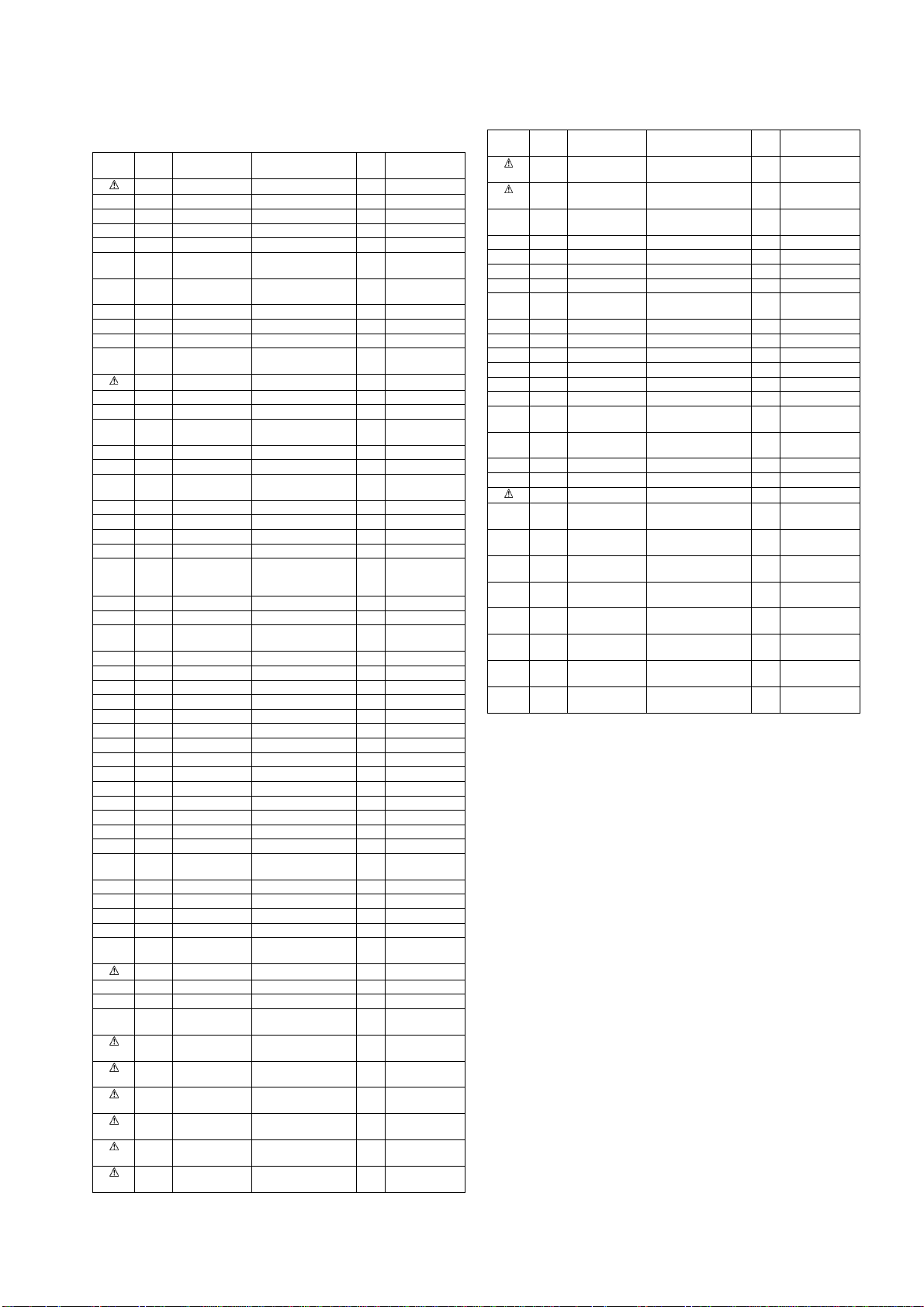
11.3. Mechanical Replacement Parts List (47 inch)
Safety Ref.
1 T6103511870 CABINET FRONT 1
2 TBMA162 PANASONIC BADGE 1
4 T6103528212 SPACE SHEET 4
5 T6550038821 SPACER SHEET 2
6 TZ6103504162 MOUNTING CF & CB 4
7 TZ6103506722 MTG C/F & C/B
8 TZ6103507095 MTG C/F & C/B
13 TZ6103504285 MOUNTING DEC 2
16 TZ6103529578 SHIELD RC 1
17 T6103504179 DEC LED 1
19 T6451032973 FLEXIBLE FLAT
20 T6103511887 LID BACK 1
21 T4112062406 SCR TPG BRZ 4X10 10
22 T6103510545 LABEL RATING 1
24 T6103504407 LABEL FOR AC
25 T4112168603 SCR FLT 4X12 23
26 T4111899003 SCR BIN 4X6 13
27 T6103534565 BACK CABINET
32 T6103531052 DEC BUTTON 1
33 T6103504421 DEC AV ENGLISH 1
34 TZ6103511917 BUTTON UNIT 1
35 T6103450971 EARTH LVDS 1
36 T4111926402 SCR S-TPG
38 T6520033436 L-SPEAKER-8 1
39 T6520033429 R-SPEAKER-8 1
40 T6550022554 ADHESIVE CLOTH
44 T4110365509 SCR PAN+SW+W 3X8 19
45 T6103505701 FIXER BOSS B 1
49 T3120730406 SPECIAL SCREW 6
50 T4110759407 SCR TPG BRZ 3X8 3
51 T4110418601 SCR PAN 3X6 2
52 TZ6103504278 AC HOLDER ASSY 1
53 T6103505688 FIXER AC CORD A 1
55 T6520033412 AC INLET 1
56 T4112205902 SCR BRZ 3X10 2
57 T4112206206 NUT HEX 3 2
59 T6103407241 GASKET AW 1
60 T6103341279 GASKET AW 2
61 T9550003837 FIXER HOOK 3
64 T9450403003 CORE-FERRITE 1
67 T6103529950 CAS ACCESSORIES A1
68 T6103534206 CARTON CASE 1
69 T6103507200 BAG 1
70 T6103529714 CUSHION TOP 1
71 T6103529745 CUSHION BTM 1
72 TMMX169 AC CORD CLAMPER B2
73 K2CT3YY00016 AC CORD 1
75 N2QAYB000535 REMOTE CONTROL 1
76 T6103528281 BAG MANUAL 1
77 T6103509167 CD-ROM-OWNERS
78 T6103509297 QUICK SETUP
78 T6103526515 QUICK SETUP
78 T6103526522 QUICK SETUP
78 T6103526539 QUICK SETUP
78 T6103526546 QUICK SETUP
78 T6103526553 QUICK SETUP
Part No. Part Name &
No.
Description
TOP
BTM
CABLE
CORD
ASSY
BRZ+FLG 3.0X8.0
V
TAPE
MANUAL
GUIDE (ENGLISH)
GUIDE (GERMAN)
GUIDE (ITALIAN)
GUIDE (DUTCH)
GUIDE (FRENCH)
GUIDE (DANISH)
Safety Ref.
Pcs Remarks
1
1
1
1
1
25
24
1
1
1
1
1
1
1
No.
78 T6103526560 QUICK SETUP
78 T6103526577 QUICK SETUP
80 T6550038838 SPACER SHEET
81 TZ6103504209 MTG PANEL TOP L 1
82 TZ6103504216 MTG PANEL TOP R 1
83 T6103504223 MTG PANEL BTM L 1
84 T6103504247 MTG PANEL BTM R 1
85 T6103529974 SPACER CUSHION
86 T6103519784 FIXER CABLE 1
87 T4111922503 SCR PAN+SW 4X6 1
88 T4111898907 SCR BIN 4X4 2
89 T6103531670 T-ALUMINUM 2
90 T6103533506 T-ALUMINUM A 2
91 T6103534107 T-ALUMINUM C 1
92 T6550041715 POLY SHEET
93 T6103533940 HEAT CAUTION
94 T6103535043 T-EPOXY 2
95 K2CN3YY00004 CORD POWER-2.0MK 1
T6451038890 LCD PANEL 1
T6520033184 LVDS CABLE 51P
T6103511559 CABLE (K39G-
T6103511467 CABLE (K16A-
T6103520490 CABLE (K38H-
T6103511528 CABLE (K72E-
T9103216158 CABLE (K16C-
T6103511498 CABLE (K72D-
T6103520483 CABLE (K16B-
TH-42LF20E / TH-47LF20E
Part No. Part Name &
Description
GUIDE (SPANISH)
GUIDE (SWEDISH)
C8ZK
BTM A
1700X1300NG
CARD
(LCD PANEL-KLVP)
K19G)
K6A)
JK39H)
K10E)
K6C)
K10D)
K6B)
Pcs Remarks
1
1
2
1
1
1
1
1
1
1
1
1
1
1
51
Page 52
TH-42LF20E / TH-47LF20E
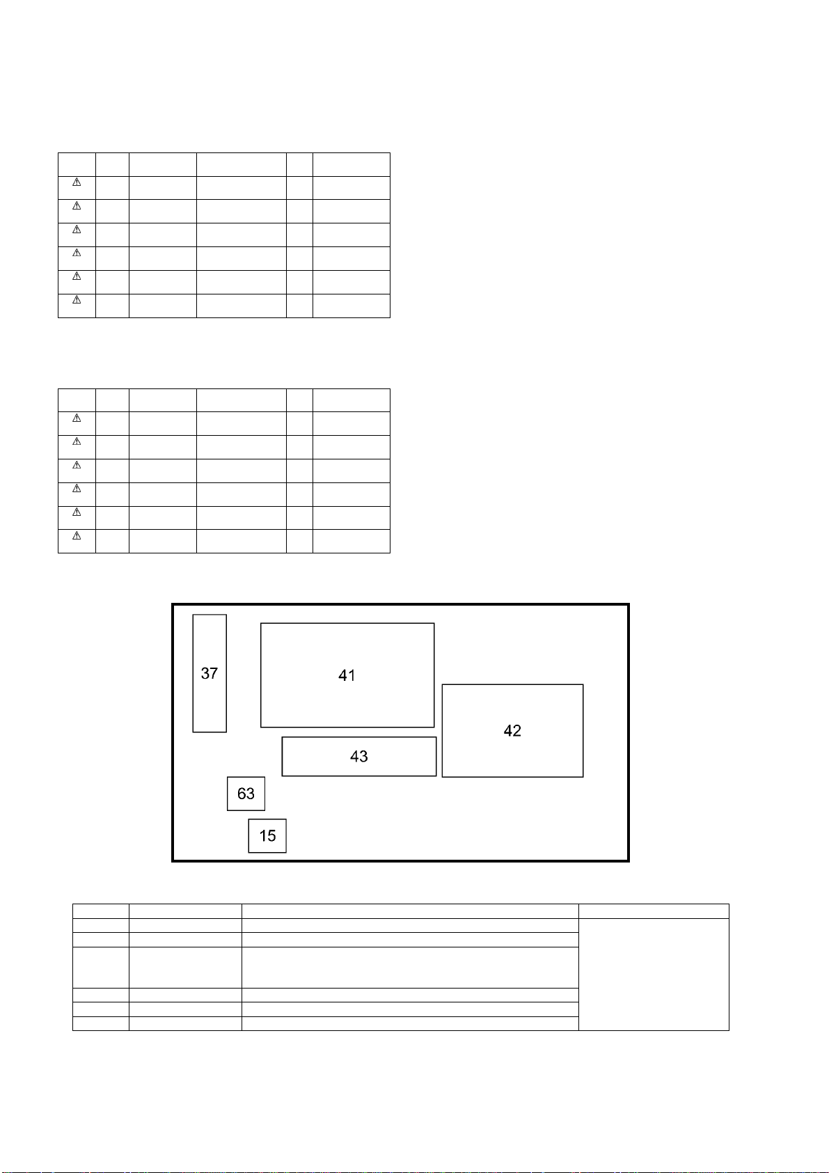
11.4. Electrical Replacement Boards list (42 inch)
Note: All boards are Non serviceable.
Safety Ref.
15 T6103500829 CIRCUIT BOARD-
37 T6103500836 CIRCUIT BOARD-
41 T6103499710 CIRCUIT BOARD-
42 T6103528403 CIRCUIT BOARD-
43 T6103500812 CIRCUIT BOARD-
63 T6103516394 CIRCUIT BOARD-
Part No. Part Name &
No.
Description
RC+LED
KEY SW
POWER
MAIN
JACK
CONNECTOR
Pcs Remarks
1
1
1
1
1
1
11.5. Electrical Replacement Boards list (47 inch)
Note: All boards are Non serviceable.
Safety Ref.
15 T6103500829 CIRCUIT BOARD-
37 T6103500836 CIRCUIT BOARD-
41 T6103534091 CIRCUIT BOARD-
42 T6103528403 CIRCUIT BOARD-
43 T6103500812 CIRCUIT BOARD-
63 T6103516394 CIRCUIT BOARD-
Part No. Part Name &
No.
Description
RC+LED
KEY SW
POWER
MAIN
JACK
CONNECTOR
Pcs Remarks
1
1
1
1
1
1
11.6. Boards Layout
Ref.No. Board Name Function Remarks
15 RC+LED Remote Receiver, LED
37 KEY SW Control Button
41 POWER
42 MAIN Main, Audio & Video Signal Processor, HDMI in, PC in
43 JACK AV Terminal
63 CONNECTOR Connection board for RC+LED
Power (AC/DC), DC-DC
Non serviceable
P-Board should be exchanged for service.
All boards are Non serviceable.
52
 Loading...