

Page 1
1
Panasonic Corporation 2014
Unauthorized copying and distribution is
a violation of law.
c
Hints for Board Repair
( 32inch, 1 board model )
Order No. ITD1412904GE
Model No.
Ver. 1.0
TH-32A400G/K/T/X/V
TH-32A405D
TH-32A408K
TH-32A409K
TH-32A410D/G/K/M/X/V
1
Page 2
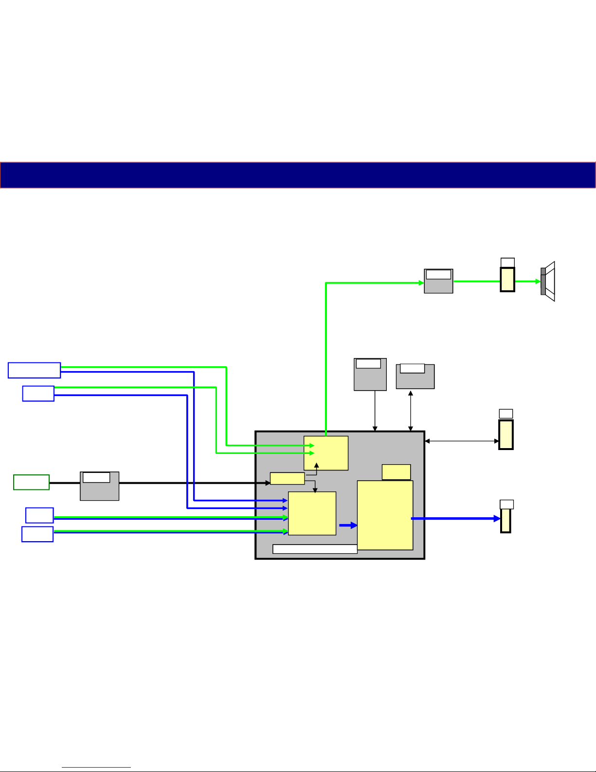
IC8001 RTD2644
Video
I/F
Digital Video
Processor
Resize MIX
I/P conv.
Pixel conv.
AI Gamma
OSD
AMP
IC4900
(V)
(Y Pb Pr)
A12
Demod
SPI
ROM
IC8901
A10
USB
HDMI
Audio
I/F
Signal Flow
(TNP4G573**)
Component
Video
A21
LED/
Remote
(K Board)
DEMOD
IC6750
Antenna
EEPROM
IC8902
(IF)
2
Page 3
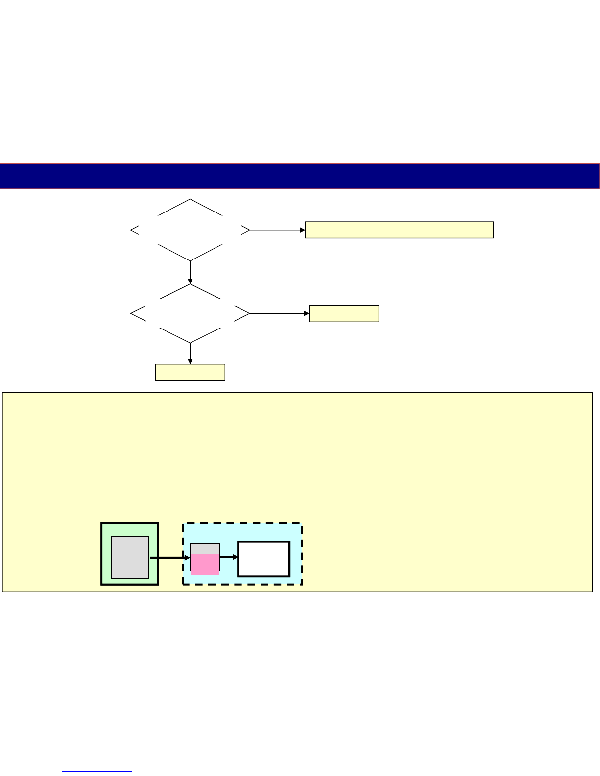
Troubleshoot of Picture Problem
3
<LCD Panel Test Mode> :
When abnormal picture is displayed, troubleshoot by the test pattern in LCD module.
If the picture is no problem, A board must be defective.
If the picture is also abnormal, LCD panel module must be defective.
How to enter :
While pressing "volume(-)" button of the TV unit,
press "option" button of the remote control 3 times within 2 seconds.
How to exit :
Disconnect AC plug
A
IC8001
(RTK2644)
Resize
IP conv.
LCD Panel
LCD Panel Module
T-CON
Test
Pattern
#) The test pattern is created by the circuit
in LCD Panel Module(T-CON board).
No
Yes
Is the picture of all
Input Source NG ?
Check by LCD
Panel Test Mode
Check the input circuit / IC8001
NG
LCD Panel
IC 8001
OK
Page 4
LCD Panel
Module
(LED
Backlight)
Power Supply Part
IC7503
IC7301
8
Start
Vcc
5
T7301
Q7301
6
D7303
R7342
-44
16V
2
PC7301
feedback
10
9
STB5.3V
IC7501
EN
HV
VCC
DRV
FB
Q7510
P2
P16.3V
SUB-ON
VCC
Q7502
D7507
C7502
D7502
C7512
3
LED
Drive
IC7800
BL-ON(Hi=enable)
Q7801
L7806/07
4
Anode
Cathode
Vcc
1
Panel-PWM
Q7803
9
10
8
Panel-PWM
Bright
Dark
Lighting Period
OFF
0V
D7102
Rectifier
14
BL-SOS
(1 blink)
SUB3.3V
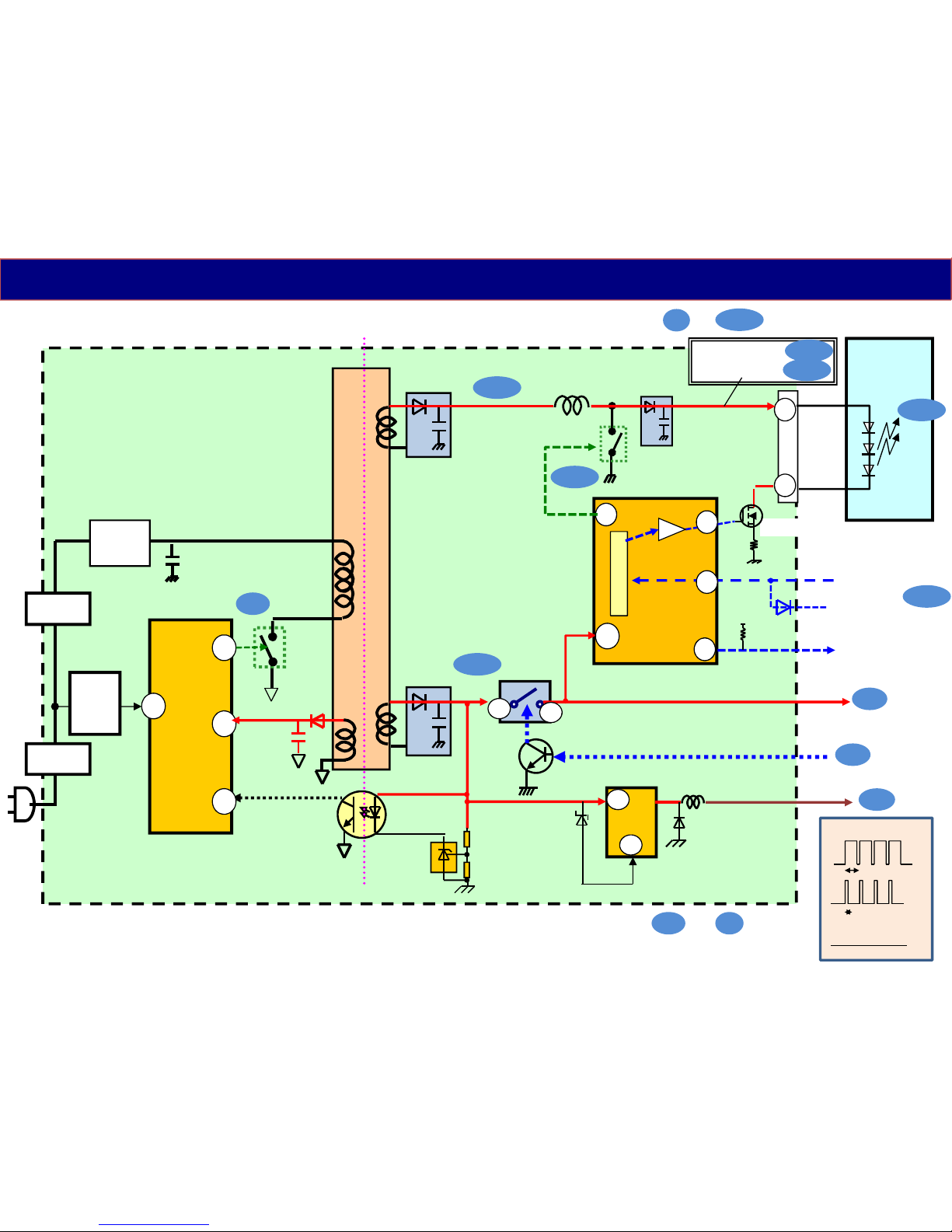
Power Supply Distribution (1/2)
(TNP4G573**)
L7502
D7317
C7513
L
O
G
I
C
4
CF7101
F7101
OFF/STB=38V
ON= 71V
1st
2nd
3rd
6th
7th
13th
14th
15th
(2nd)
1-3
5-8
D7800
C7817
38V
IC7301 automatically starts working after AC plug in. (always working from to )
IC7800 starts working after input Vcc and BL-ON/Panel-PWM signal.
4th1st
14th
VLED
The power on sequence is describe by the number of the symbol. ( - )
1st
15th
2nd
Page 5
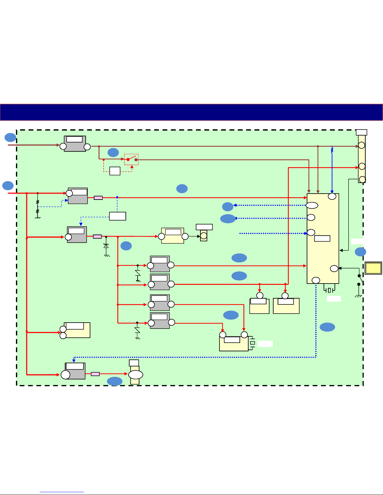
Signal Processing Part
RTD2644
IC8001
A10
P16.3V
3
LED
Remote
DCDCEN
X8301
Power Supply Distribution (2/2)
5
SUB3.3V
Power
_SW
PANEL12V_ON
P16.3V
TUNER
IC6750
8 21
X6750
3.3V
IC8708
8
1
STB5.3V/STB5V
V33A/V33HDMI/V33POR
SUB5V
5V
IC8702
L8702
2
DCDCEN2
SUB3.3V
3.3V
IC8711
4
TNR3.3V/SITU_3.3V
3.3V
IC8709
3
TNR1.8V/SITU_1.8V
1.8V
IC8705
3
DDR1.8V/DDRV
1.8V
IC8707
4
4
3
3
4
SPI
IC8901
EEPROM
IC8902
8
8
(TNP4G573**)
STB3.3V/STB_M3.3V/V33AMAIN/ETN_3V3/V33IO/V33LVDS
USB_Pwr
IC5602
JK8601
USB
1
1 6
AMP
IC4900
2
3
A21
To LCD
Module
(T-CON)
27-30
12V
IC8300
2
PNL12V
L8300
PANEL12V_ON
VCCK1.1V/V11CORE
1.1V
IC8700
L8700
2
EN
Tr x2
Q8002
Tr
KEY3
122
SUB-ON
EN
110
56
BL-ON / Panel-PWM
64
STBRST
131
65
BL-SOS (1 blink)
3rd
4th
6th
7th
8th
9th
11th
13th
12th
10th
10th
10th
1
Remote
5th
5
Page 6
OK
OK
All OK
No or
Low voltage
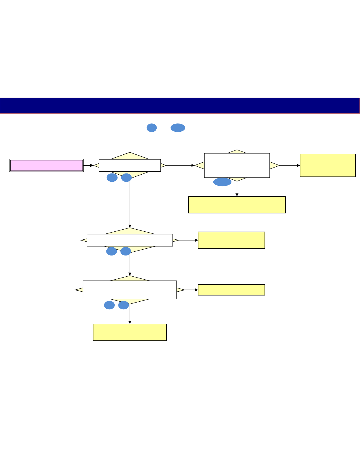
No Power/No Operation
< symptom >
No signal = IC8001
No P16.3V = Q7502/D7502
NG
Troubleshoot of Power On Problem (1/2)
Check output voltage of
STB5V, STB3.3V
Check TV_SUB_ON signal (=High)
and voltage P16.3V line
Power IC of Defective line
Check short circuit of each power line
SUB5V,SUB3.3V,DDR1.8V,VCCK1.1V
(PNL12V,TNR3.3V,TNR1.8V)
F7101/CF7101
Q7301/IC7301/D7317,
D7502/IC7503
IC7503/IC8708
(check short circuit of STB power line)
OK
NG
Check input voltage of
IC7503 (16V) and
Check VLED voltage (38V)
at P2-3pin
If all output voltages are OK,
IC8001
NG
Check by power on sequence ( from to )
1st 13th
3rd 4th
2nd
6th 7th
8th 9th
6
Page 7
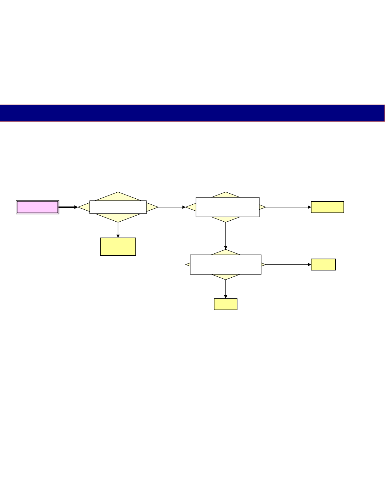
SOS 1 blink
Q7801,7803
(IC7800)
Shorted
OK
< symptom >
Troubleshoot of Power On Problem (2/2)
Check short circuit of
Q7801,7803
Voltage Check of VLED
Just before shutdown
(rise up from 38V to 71V)
IC7800
Keep 0V
Rise up
(Not 0V)
Voltage Check of PWM
Signal input (pin4) of C7800
Just before shutdown
IC8001
OK
(71V)
NG
(38V or lower)
LCD Panel
7
Page 8
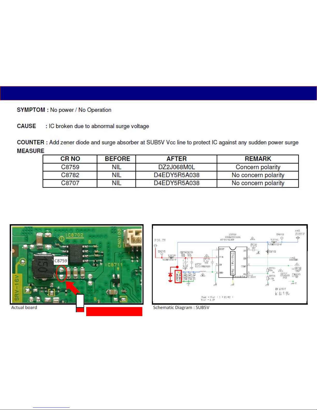
Parts Change Note
1. Add zener diode (DZ2J068M0L) to pad of C8759 (no use)
POLARITY MARKING
8
Page 9
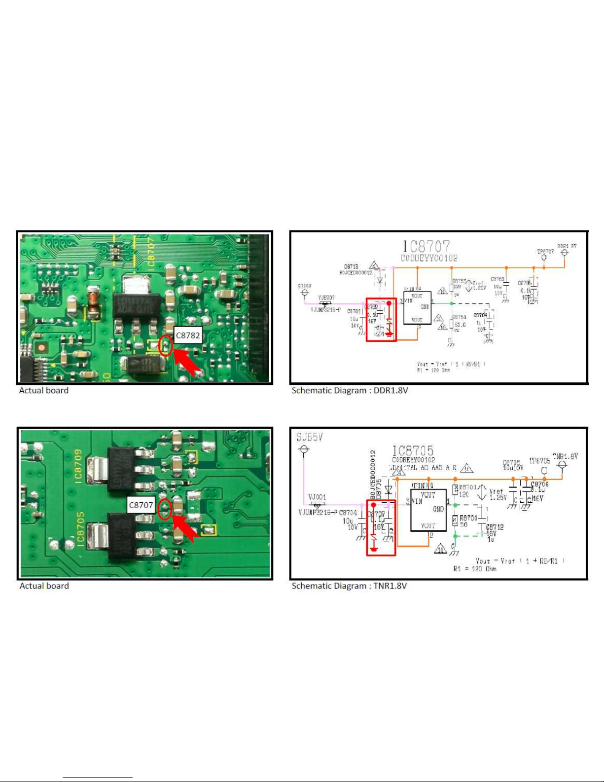
2. Add surge absorber (D4EDY5R5A038) to pad of C8782 (no use)
3. Add surge absorber (D4EDY5R5A038) to pad of C8707 (no use)
9
Page 10
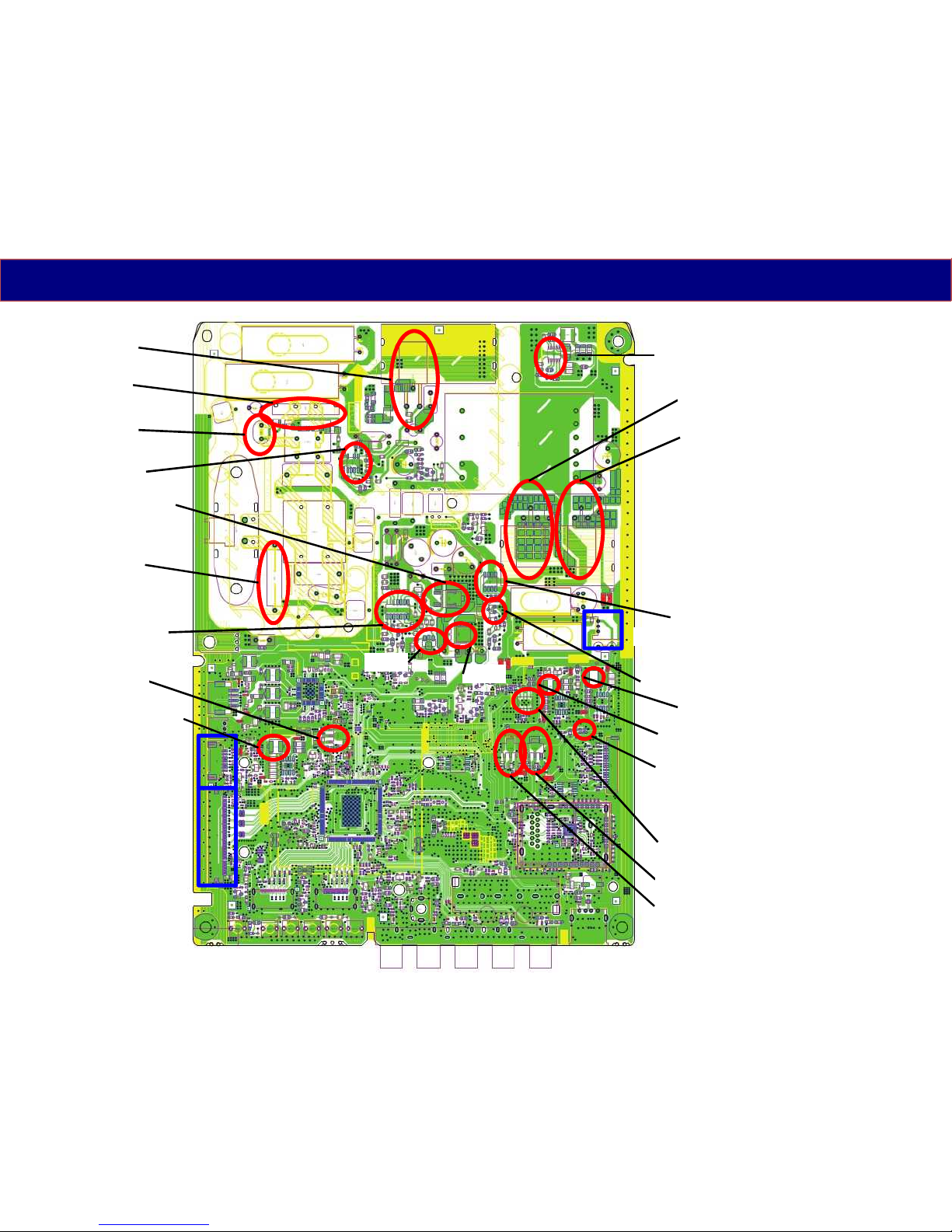
Parts Location
Q7502
IC7301
F7101
CF7101
Q7301
D7507
D7102
D7502
IC7503(STB5V)
IC7800
Q7801
Q7803
Q7510
D7800
P2
A10
IC8708 (STB3.3V)
L8700 (Left side=VCCJ1.1V)
L8702 (Left side=SUB5V)
L8300 (Left side=PNL12V)
A21
IC8707 (DDR1.8V)
IC8711 (SUB3.3V)
IC8705 (TNR1.8V)
IC8709 (TNR3.3V)
10
Page 11
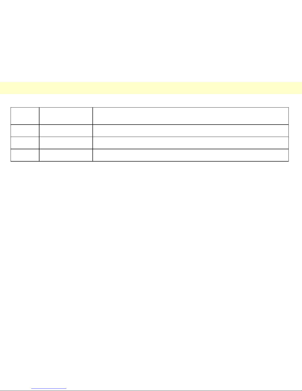
Revision History
Version Issued/Revised
date
Revised content
Ver. 1.0 11.Dec.2014 First version
11
 Loading...