

Panasonic Pure IP-PBX KX-TDE600, TDE600, KXTDA620, TDA620, KX-TDE620 Installation Manual
...Page 1
Installation Manual
Pure IP-PBX
Model No.
KX-TDE600
Thank you for purchasing a Panasonic Pure IP-PBX.
Please read this manual carefully before using this product and save this manual for future use.
KX-TDE600: PGMPR Software File Version 3.0000 or later
SD Logo is
a trademark.
Document Version: 2009-12
Page 2
System Components
System Components
System Components Table
Category Model No. Description
Basic Shelf KX-TDE600 Basic Shelf
Main Processing Card Main Processing Card (IPCEMPR)
IPCEMPR Optional Cards KX-TDE0105 Memory Expansion Card (IPCMEC)
KX-TDE0110 16-Channel VoIP DSP Card (DSP16)
KX-TDE0111 64-Channel VoIP DSP Card (DSP64)
KX-TDA0196 Remote Card (RMT)
Optional Shelf Expansion
Cards
Expansion Shelf KX-TDE620 Expansion Shelf
Built-in Shelf
Expansion Card
Mounting Kit KX-TDA6201 Mounting Kit for expanding to a 3- or 4- shelf System
Activation Key Codes
*1
KX-TDA6110 Bus Master Card (BUS-M)
KX-TDA6111 Bus Master Expansion Card (BUS-ME)
Bus Slave Card (BUS-S)
KX-NCS4102 2-Channel IP Trunk Activation Key (2 IP Trunk)
KX-NCS4104 4-Channel IP Trunk Activation Key (4 IP Trunk)
KX-NCS4201 1-Channel IP Softphone/IP Proprietary Telephone
Activation Key (1 IP Softphone/IP PT)
KX-NCS4204 4-Channel IP Softphone/IP Proprietary Telephone
Activation Key (4 IP Softphone/IP PT)
KX-NCS4208 8-Channel IP Softphone/IP Proprietary Telephone
Activation Key (8 IP Softphone/IP PT)
KX-NCS4216 16-Channel IP Softphone/IP Proprietary Telephone
Activation Key (16 IP Softphone/IP PT)
KX-NCS4501 1-Channel IP Proprietary Telephone Activation Key
(1 IP PT)
KX-NCS4504 4-Channel IP Proprietary Telephone Activation Key
KX-NCS4508 8-Channel IP Proprietary Telephone Activation Key
KX-NCS4516 16-Channel IP Proprietary Telephone Activation Key
KX-NCS4701 1-Channel SIP Extension Activation Key
2 Installation Manual Document Version 2009-12
(4 IP PT)
(8 IP PT)
(16 IP PT)
(1 SIP Extension)
Page 3

Category Model No. Description
KX-NCS4704 4-Channel SIP Extension Activation Key
(4 SIP Extension)
KX-NCS4708 8-Channel SIP Extension Activation Key
(8 SIP Extension)
KX-NCS4716 16-Channel SIP Extension Activation Key
(16 SIP Extension)
KX-NCS4950 Activation Key for Software Upgrade to Enhanced Version
(Software Upgrade 01)
KX-NCS2101 Activation Key for CA Basic for 1 User (CA Basic 1user)
KX-NCS2105 Activation Key for CA Basic for 5 Users (CA Basic 5users)
KX-NCS2110 Activation Key for CA Basic for 10 Users (CA Basic
10users)
KX-NCS2140 Activation Key for CA Basic for 40 Users (CA Basic
40users)
KX-NCS2149 Activation Key for CA Basic for 128 Users (CA Basic
128users)
System Components
KX-NCS2201 Activation Key for CA PRO for 1 User (CA Pro 1user)
KX-NCS2205 Activation Key for CA PRO for 5 Users (CA Pro 5users)
KX-NCS2210 Activation Key for CA PRO for 10 Users (CA Pro 10users)
KX-NCS2240 Activation Key for CA PRO for 40 Users (CA Pro 40users)
KX-NCS2249 Activation Key for CA PRO for 128 Users (CA Pro
128users)
KX-NCS2301 Activation Key for CA ACD Monitor for 1 ICD Supervisor
(CA Supervisor 1user)
Virtual CO line Card - Virtual 16-Channel VoIP Gateway Card (V-IPGW16)
- Virtual 16-Channel SIP CO Line Card (V-SIPGW16)
Virtual Extension Cards - Virtual 32-Channel VoIP Extension Card (V-IPEXT32)
- Virtual 32-Channel SIP Extension Card (V-SIPEXT32)
- Virtual 4 IP Cell Station Interface Card (V-IPCS4)
Physical CO Line Cards KX-TDA0187 T-1 Trunk Card (T1)
KX-TDA0193 8-Port Caller ID Card (CID8)
KX-TDA0290 PRI Card (PRI23)
KX-TDA0484 4-Channel VoIP Gateway Card (IP-GW4E)
Physical Extension Cards KX-TDA0143 4 Cell Station Interface Card (CSIF4)
Document Version 2009-12 Installation Manual 3
KX-TDA0490 16-Channel VoIP Gateway Card (IP-GW16)
KX-TDA6181 16-Port Analog Trunk Card (ELCOT16)
KX-TDA0144 8 Cell Station Interface Card (CSIF8)
Page 4

System Components
Category Model No. Description
KX-TDA0170 8-Port Digital Hybrid Extension Card (DHLC8)
KX-TDA0171 8-Port Digital Extension Card (DLC8)
KX-TDA0172 16-Port Digital Extension Card (DLC16)
KX-TDA0173 8-Port Single Line Telephone Extension Card (SLC8)
KX-TDA0177 16-Port Single Line Telephone Extension Card with Caller
ID (CSLC16)
KX-TDA0470 16-Channel VoIP Extension Card (IP-EXT16)
KX-TDA6174 16-Port Single Line Telephone Extension Card (ESLC16)
KX-TDA6175 16-Port Single Line Telephone Extension with Message
Lamp Card (EMSLC16)
KX-TDA6178 24-Port Single Line Telephone Extension Card with Caller
ID (ECSLC24)
Other Physical Cards KX-TDA0161 4-Port Doorphone Card (DPH4)
KX-TDA0164 4-Port External Input/Output Card (EIO4)
Power Supply Units
(PSUs)
Cell Stations
2.4 GHz KX-T0141 2-Channel Cell Station Unit Using a DHLC/DLC Card
(CSs)
DECT 6.0 KX-T0155 DECT 6.0 2-Channel Cell Station Unit Using a DHLC/
KX-TDA0168 Extension Caller ID Card (EXT-CID)
KX-TDA0190 Optional 3-Slot Base Card (OPB3)
KX-TDA0191 4-Channel Message Card (MSG4)
KX-TDA0194 4-Channel Simplified Voice Message Card (ESVM4)
KX-TDA6166 16-Channel Echo Canceller Card (EECHO16)
KX-TDA0103 L-Type Power Supply Unit (PSU-L)
KX-TDA0104 M-Type Power Supply Unit (PSU-M)
(PT-interface CS) for 2.4 GHz Portable Station
KX-TDA0142 3-Channel Cell Station Unit Using a CSIF Card for 2.4 GHz
Portable Station
KX-T0151 2-Channel Cell Station Unit Using a DHLC/DLC Card
(PT-interface CS) for 2.4 GHz Portable Station
KX-TDA0152 3-Channel Cell Station Unit Using a CSIF Card for 2.4 GHz
Portable Station
DLC Card (PT-interface CS) for DECT 6.0 Portable Station
KX-TDA0156 DECT 6.0 4-Channel Cell Station Unit Using a CSIF Card
KX-T0158 DECT 6.0 8-Channel Cell Station Unit Using a DHLC/
KX-NCP0158 DECT 6.0 8-Channel IP Cell Station Unit Using a
4 Installation Manual Document Version 2009-12
for DECT 6.0 Portable Station
DLC Card (PT-interface CS) for DECT 6.0 Portable Station
V-IPCS4 Card for DECT 6.0 Portable Station
Page 5

System Components
Category Model No. Description
Proprietary Equipment KX-A258 Blank Slot Cover
KX-T30865 Doorphone
KX-T7765
KX-T7775
*1
Note that the types of activation keys are subject to change without notice. For CA activation keys, refer to the documentation for
CA.
Unsupported Optional Equipment
Most optional equipment supported by the KX-TDA100/KX-TDA200/KX-TDA600/KX-TDE100/KX-TDE200 can
also be used with the KX-TDE600. However, the items listed below are not supported by the KX-TDE600.
Category
Model No. Description
MPR Optional Cards KX-TDA0105 Memory Expansion Card (MEC)
KX-TDA6105 Memory Expansion Card (EMEC)
CO Line Cards KX-TDA0180 8-Port Analog Trunk Card (LCOT8)
KX-TDA0181 16-Port Analog Trunk Card (LCOT16)
KX-TDA0183 4-Port Analog Trunk Card (LCOT4)
KX-TDA0480 4-Channel VoIP Gateway Card (IP-GW4)
Extension Cards KX-TDA0174 16-Port Single Line Telephone Extension Card (SLC16)
KX-TDA0175 16-Port Single Line Telephone Extension with Message
Lamp Card (MSLC16)
Other Cards KX-TDA0166 16-Channel Echo Canceller Card (ECHO16)
KX-TDA0410 CTI Link Card (CTI-LINK)
Optional SD Memory
Cards
KX-TDA0920 SD Memory Card for Software Upgrade to Enhanced
KX-TDA6920
Version
Activation Key Code KX-NCS4910 Activation Key for Software Upgrade to Enhanced
Version (Software Upgrade 01)
PSU KX-TDA0108 S-Type Power Supply Unit (PSU-S)
Equipment Compatibility
Compatible Panasonic Proprietary Telephones
The PBX supports the following telephones:
• IP proprietary telephones (e.g., KX-NT300 series)
• IP softphones (e.g., KX-TDA0350)
• Digital proprietary telephones (e.g., KX-DT300 series)
• Analog proprietary telephones (e.g., KX-T7700 series)
• Portable stations (e.g., KX-TD7690)
• DSS consoles (e.g., KX-DT390)
Document Version 2009-12 Installation Manual 5
Page 6
System Components
• Single line telephones
Incompatible Panasonic Proprietary Telephones
The PBX does not support the following telephones:
• KX-T30800 series proprietary telephones and DSS consoles
• KX-T61600 series proprietary telephones and DSS consoles
• KX-T123200 series proprietary telephones and DSS consoles
Note
• For the equipment (e.g., Add-on Key Module, USB Module, Headset
particular telephone, refer to the telephone’s manual.
*1
) that can be connected to a
• For other equipment that can be connected to the PBX, refer to "1.1.3 System Connection Diagram".
*1
The KX-T7090 headset can be connected to the KX-T7000, KX-T7200, KX-T7300, and KX-T7400 series telephones.
Notice
• This PBX supports SIP Extensions. However, some PBX features may not be available for SIP Extensions,
depending on your telephone type.
• Under power failure conditions, the connected telephones may not operate. Please ensure that a separate
telephone, not dependent on local power, is available for emergency use.
• Prior to connection of this product, please verify that the intended operating environment is supported.
Satisfactory performance cannot be guaranteed for the following:
– interoperability and compatibility with all devices and systems connected to this product
– proper operation and compatibility with services provided by telecommunications companies over
connected networks
Safety Notices
Please observe the safety notices in this manual in order to avoid danger to users or other people, and prevent
damage to property.
The notices are classified as follows, according to the severity of injury or damage:
WARNING
CAUTION
List of Abbreviations
• APT ® Analog Proprietary Telephone
• CA ® Communication Assistant
• DPT ® Digital Proprietary Telephone
• IP-PT ® IP Proprietary Telephone
• PS ® Portable Station
• PT ® Proprietary Telephone
• SIP Extension ® Session Initiation Protocol Extension (SIP hardphones/SIP softphones)
• SLT ® Single Line Telephone
This notice means that misuse could result in death or serious injury.
This notice means that misuse could result in injury or damage to property.
6 Installation Manual Document Version 2009-12
Page 7

SAVE THESE INSTRUCTIONS
Important Safety Instructions
Important Safety Instructions
When using your telephone equipment, basic safety precautions should always be followed to reduce the risk
of fire, electric shock and injury to persons, including the following:
• Do not use the product near water, for example, near a bathtub, wash bowl, kitchen sink, or laundry tub,
in a wet basement, or near a swimming pool.
• Avoid using wired telephones during an electrical storm. There is a remote risk of electric shock from
lightning.
• Do not use a telephone in the vicinity of a gas leak to report the leak.
Document Version 2009-12 Installation Manual 7
Page 8

SAVE THESE INSTRUCTIONS
Important Information
Important Information
WARNING
SAFETY REQUIREMENTS
For All Telephone Equipment
• Do not install the product in any other way than described in relevant manuals.
• The product must only be installed and serviced by qualified service personnel. The product should be
used as-is from the time of purchase; it should not be disassembled or modified. Disassembly or
modification can cause a fire, electric shock, or damage to the product.
• Do not install the product in a place exposed to rain or moisture, or a place where water, oil, or other liquids
can drip or splash onto on the product. Such conditions can lead to fire or electric shock, and may impair
the performance of the product.
• Follow all warnings and instructions marked on the product.
• Do not place the product on an unstable or uneven surface. If the product were to fall over, it may cause
injury or damage to the product.
• Products that require a power source should only be connected to the type of electrical power supply
specified on the product label. If you are not sure of the type of power supply to your home, consult your
dealer or local power company.
• For safety purposes some products are equipped with a grounded plug. If you do not have a grounded
outlet, please have one installed. Do not bypass this safety feature by tampering with the plug.
• Do not supply power to a combination of devices that exceeds the total rated capacity of the wall outlets
or extension cables used. If outlets, power strips, extension cords, etc. are used in a manner that exceeds
their rated capacity, they emit large amounts of heat, which could cause a fire.
• Unplug the product from the wall outlet and have it serviced by qualified service personnel in the following
cases:
a. When the power supply cord or plug is damaged or frayed.
b. If liquid has been spilled into the product.
c. If the product has been exposed to rain or water.
d. If the product does not operate according to the operating instructions. Adjust only the controls that are
explained in the operating instructions. Improper adjustment of other controls may result in damage
and may require service by a qualified technician to restore the product to normal operation.
e. If the product has been dropped or the cabinet has been damaged.
f. If product performance deteriorates.
For the PBX
• If damage to the unit exposes any internal parts, disconnect the power supply cord immediately and return
the unit to your dealer.
• To prevent fires, electric shock, injury, or damage to the product, be sure to follow these guidelines when
performing any wiring or cabling:
a. Before performing any wiring or cabling, unplug the product's power cord from the outlet. After
completing all wiring and cabling, plug the power cord back into the outlet.
b. When laying cables, do not bundle the product's power cord with the power cords of other devices.
c. Do not place any objects on top of the cables connected to the PBX.
d. When running cables along the floor, use protectors to prevent the cables from being stepped on.
e. Do not run any cables under carpeting.
8 Installation Manual Document Version 2009-12
Page 9

Important Information
• Unplug all installed shelves of the system from the AC outlet if it emits smoke, an abnormal smell or makes
unusual noise. These conditions can cause fire or electric shock. Confirm that smoke has stopped and
contact an authorized Panasonic Factory Service Center.
• Danger of explosion exists if a battery is incorrectly replaced. Replace only with the same or equivalent
type recommended by the battery manufacturer. Dispose of used batteries according to the
manufacturer’s instructions.
• Make sure that the wall that the shelf will be attached to is strong enough to support the shelf. If not, it is
necessary for the wall to be reinforced.
• Only use the wall-mounting equipment (anchor plugs, screws, metal bracket) included with the PBX.
• When this product is no longer in use, make sure to detach it from the wall.
• Do not insert objects of any kind into this product, as they may touch dangerous voltage points or short out
parts that could result in a fire or electric shock.
CAUTION
SAFETY REQUIREMENTS
For All Telephone Equipment
• Unplug the product from the wall outlet before cleaning. Wipe the product with a soft cloth. Do not clean
with abrasive powders or with chemical agents such as benzene or thinner. Do not use liquid cleaners or
aerosol cleaners.
• The product should be kept free of dust, moisture, high temperature (more than 40 °C [104 °F]) and
vibration, and should not be exposed to direct sunlight.
For the PBX
• Before touching the product (PBX, cards, etc.), discharge static electricity by touching ground or wearing
a grounding strap. Failure to do so may cause the PBX to malfunction due to static electricity.
• When driving the screws into the wall, be careful to avoid touching any metal laths, wire laths or metal
plates in the wall.
• When relocating the equipment, first disconnect the telecom connection before disconnecting the power
connection. When the unit is installed in the new location, reconnect the power first, and then reconnect
the telecom connection.
• The power supply cord is used as the main disconnect device. Ensure that the AC outlet is located near
the equipment and is easily accessible.
• The SD Memory Card poses a choking hazard. Keep the SD Memory Card out of reach of children.
• Slots and openings in the front, back and bottom of the cabinet are provided for ventilation; to protect it
from overheating, these openings must not be blocked or covered. The openings should never be blocked
by placing the product on a bed, sofa, rug, or other similar surface while in use. The product should never
be placed near or over a radiator or other heat source. This product should not be placed in a sealed
environment unless proper ventilation is provided.
SECURITY REQUIREMENTS
In order to use the PBX safely and correctly, the Security Requirements below must be observed. Failure to
do so may result in:
• Loss, leakage, falsification or theft of user information.
• Illegal use of the PBX by a third party.
• Interference or suspension of service caused by a third party.
What is User Information?
User Information is defined as:
Document Version 2009-12 Installation Manual 9
Page 10

Important Information
1. Information stored on the SD Memory Card
Phonebook data, user IDs, system settings data, passwords (User/Administrator/Installer), Personal
Identification Numbers (PINs), etc.
2. Information sent from the PBX to a PC or other external device:
Phone call data (including telephone numbers of outside parties), call charge data, etc.
Requirements
1. The SD Memory Card contains software for all the processes of the PBX and all customer data. It can be
easily removed and taken away from the PBX by a third party. Therefore, do not allow unauthorized access
to prevent data leakage.
2. Always make backups of data stored on the SD Memory Card. For details, refer to "2.6.2 Utility—File
Transfer PC to PBX (SD Card)" and "2.6.3 Utility—File Transfer PBX (SD Card) to PC" in the PC
Programming Manual.
3. To prevent illegal access from the Internet, activate a Firewall.
4. To avoid unauthorized access and possible abuse of the PBX, we strongly recommend:
a. Keeping the password secret.
b. Selecting a complex, random password that cannot be easily guessed.
c. Changing your password regularly.
5. Perform the following when sending the PBX for repair or handing it over to a third party.
a. Make a backup of data stored on the SD Memory Card.
b. Using an SD formatter, format the SD Memory Card so that information cannot be retrieved from it.
6. To prevent data leakage, render the SD Memory Card physically unusable before disposal.
7. When user information is sent from the PBX to a PC or other external device, the confidentiality of that
information becomes the responsibility of the customer. Before disposing of the PC or other external device,
ensure that data cannot be retrieved from it by formatting the hard disk and/or rendering it physically
unusable.
Notice
SAFETY REQUIREMENTS
For All Telephone Equipment
• Read and understand all instructions.
For the PBX
• When placing the metal bracket, make sure that the "TOP" arrow is pointing upward.
• Keep the unit away from heating appliances and devices that generate electrical noise such as fluorescent
lamps, motors and televisions. These noise sources can interfere with the performance of the PBX.
• If you are having problems making calls to outside destinations, follow this procedure to test the CO lines:
a. Disconnect the PBX from all CO lines.
b. Connect known working SLTs to those CO lines.
c. Make a call to an external destination using those SLTs.
If a call cannot be carried out correctly, there may be a problem with the CO line that the SLT is connected
to. Contact your telephone company.
If all SLTs operate properly, there may be a problem with your PBX. Do not reconnect the PBX to the CO
lines until it has been serviced by an authorized Panasonic Factory Service Center.
10 Installation Manual Document Version 2009-12
Page 11

Precaution
WARNING
DO NOT REMOVE
SD MEMORY CARD
WHILE POWER IS
SUPPLIED TO THE PBX
Doing so may cause the PBX to fail to
start when you try to restart the system.
Precaution
Document Version 2009-12 Installation Manual 11
Page 12

Notice for users in California
This product contains a CR coin cell lithium battery that
contains perchlorate material—special handling may
apply.
See www.dtsc.ca.gov/hazardouswaste/perchlorate
Precaution
Password Security
CAUTION
To the Administrator or Installer regarding the system password
1. Please provide all system passwords to the customer.
2. To avoid unauthorized access and possible abuse of the PBX, keep the passwords secret, and inform
the customer of the importance of the passwords, and the possible dangers if they become known to
others.
3. The PBX has default passwords preset. For security, change these passwords the first time that you
program the PBX.
4. Change the passwords periodically.
5. It is strongly recommended that passwords of 10 numbers or characters be used for maximum
protection against unauthorized access. For a list of numbers and characters that can be used in system
passwords, refer to "1.1.2 Entering Characters" in the PC Programming Manual.
6. If a system password is forgotten, it can be found by loading a backup of the system data into a PC,
and checking the password using the Maintenance Console software. If you do not have a backup of
the system data, you must reset the PBX to its factory defaults and reprogram it. Therefore, we strongly
recommend maintaining a backup of the system data. For more information on how to back up the
system data, refer to "2.5.1 Tool—SD memory backup" in the PC Programming Manual.
However, as system passwords can be extracted from backup copies of the system data file, do not
allow unauthorized access to these files.
12 Installation Manual Document Version 2009-12
Page 13

Introduction
Introduction
This Installation Manual is designed to serve as an overall technical reference for the Panasonic Pure IP-PBX,
KX-TDE600. It provides instructions for installing the hardware, and programming the PBX using the
Maintenance Console.
The Structure of this Manual
This manual contains the following sections:
Section 1 System Outline
Provides general information on the PBX, including the system capacity and specifications.
Section 2 Activation Key Installation
Describes information on activation keys, including how to obtain an activation key and install it in the SD
Memory Card.
Section 3 Installation
Describes the procedures to install the PBX. Detailed instructions for planning the installation site, installing
the shelves and optional service cards, and cabling of peripheral equipment are provided. Further
information on system expansion and peripheral equipment installation is included.
Section 4 Guide for the Maintenance Console
Explains the installation procedure, structure, and basic information of the Maintenance Console.
Section 5 Troubleshooting
Provides information on the PBX and telephone troubleshooting.
About the Other Manuals
Along with this Installation Manual, the following manuals are available:
Feature Manual
Describes all basic, optional and programmable features of the PBX.
PC Programming Manual
Provides step-by-step instructions for performing system programming using a PC.
PT Programming Manual
Provides step-by-step instructions for performing system programming using a PT.
Operating Manual
Provides operating instructions for end users using a PT, SLT, PS, or DSS Console.
About the software version of your PBX
The contents of this manual apply to PBXs with a certain software version, as indicated on the cover of this
manual. To confirm the software version of your PBX, see "How do I confirm the software version of the PBX
or installed cards?" in 2.7.1 Frequently Asked Questions (FAQ) of the PC Programming Manual, or "[190]
Main Processing (MPR) Software Version Reference" in the PT Programming Manual.
Trademarks
• The Bluetooth
Panasonic Corporation is under license.
®
word mark and logos are owned by the Bluetooth SIG, Inc. and any use of such marks by
• Microsoft, Windows, and Windows Vista are either registered trademarks or trademarks of Microsoft
Corporation in the United States and/or other countries.
• All other trademarks identified herein are the property of their respective owners.
• Microsoft product screen shot(s) reprinted with permission from Microsoft Corporation.
Document Version 2009-12 Installation Manual 13
Page 14

F.C.C. REQUIREMENTS AND RELEVANT INFORMATION
F.C.C. REQUIREMENTS AND RELEVANT
INFORMATION
1. Notification to the Telephone Company
This equipment complies with Part 68 of the FCC rules and the requirements adopted by the ACTA. On
the side of this equipment is a label that contains, among other information, a product identifier in the format
US: ACJMF04BKX-TDA600. If requested, this number must be provided to the telephone company.
Installation must be performed by a qualified professional installer. If required, provide the telephone
company with the following technical information:
• Telephone numbers to which the system will be connected
• Make: Panasonic
• Model: KX-TDE600
• Certification No.: found on the side of the unit
• Ringer Equivalence No.: 0.4B
• Facility Interface Code: 02LS2, 04DU9.BN/DN/1KN/1SN
• Service Order Code: 9.0F, 6.0P
• Required Network Interface Jack: RJ21X, RJ48C
2. Ringer Equivalence Number (REN)
The REN is used to determine the number of devices that may be connected to a telephone line. Excessive
RENs on a telephone line may result in the devices not ringing in response to an incoming call. In most
but not all areas, the sum of RENs should not exceed five (5.0). To be certain of the number of devices
that may be connected to a line, as determined by the total RENs, contact the local telephone company.
The REN for this product is part of the product identifier that has the format US: ACJMF04BKX-TDA600.
The digits represented by 04 are the REN without a decimal point (e.g., 04 is a REN of 0.4). For earlier
products, the REN is separately shown on the label.
3. Incidence of Harm to the Telephone Lines
If this equipment causes harm to the telephone network, the telephone company will notify you in advance
that temporary discontinuance of service may be required. But if advance notice isn’t practical, the
telephone company will notify the customer as soon as possible. Also, you will be advised of your right to
file a complaint with the FCC if you believe it is necessary.
4. Changes in Telephone Company Communications Facilities, Equipment, Operations and
Procedures
The telephone company may make changes in its facilities, equipment, operations or procedures that could
affect the operation of the equipment. If this happens the telephone company will provide advance notice
in order for you to make necessary modifications to maintain uninterrupted service.
5. Trouble with this equipment
If trouble is experienced with this equipment, for repair or warranty information, please see the attached
warranty, which includes the Servicenter Directory. If the equipment is causing harm to the telephone
network, the telephone company may request that you disconnect the equipment until the problem is
resolved.
6. Connection to Party Line
Connection to party line service is subject to state tariffs. Contact the state public utility commission, public
service commission or corporation commission for information.
7. Combined Use with Alarm Equipment
If your home has specially wired alarm equipment connected to the telephone line, ensure the installation
of this equipment does not disable your alarm equipment. If you have questions about what will disable
alarm equipment, consult your telephone company or a qualified installer.
Note
This equipment has been tested and found to comply with the limits for a Class B digital device, pursuant
to Part 15 of the FCC Rules. These limits are designed to provide reasonable protection against harmful
14 Installation Manual Document Version 2009-12
Page 15

F.C.C. REQUIREMENTS AND RELEVANT INFORMATION
interference in a residential installation. This equipment generates, uses, and can radiate radio frequency
energy and, if not installed and used in accordance with the instructions, may cause harmful interference
to radio communications. However, there is no guarantee that interference will not occur in a particular
installation. If this equipment does cause harmful interference to radio or television reception, which can
be determined by turning the equipment off and on, the user is encouraged to try to correct the interference
by one or more of the following measures:
• Reorient or relocate the receiving antenna.
• Increase the separation between the equipment and receiver.
• Connect the equipment into an outlet on a circuit different from that to which the receiver is connected.
• Consult the dealer or an experienced radio/TV technician for help.
CAUTION
• Any changes or modifications not expressly approved by the party responsible for compliance could
void the user’s authority to operate this device.
• When programming emergency numbers and/or making test calls to emergency numbers:
1. Remain on the line and briefly explain to the dispatcher the reason for the call before hanging up.
2. Perform such activities in the off-peak hours, such as early morning hours or late evenings.
• The software contained in the ARS and TRS features to allow user access to the network must be
upgraded to recognize newly established network area codes and exchange codes as they are placed
into service. Failure to upgrade the premises PBXs or peripheral equipment to recognize the new codes
as they are established will restrict the customer and the customer’s employees from gaining access
to the network and to these codes.
KEEP THE SOFTWARE UP-TO-DATE WITH THE LATEST DATA.
Document Version 2009-12 Installation Manual 15
Page 16

Table of Contents
Table of Contents
1 System Outline .......................................................................................19
1.1 System Construction ......................................................................................................20
1.1.1 Basic System ..................................................................................................................20
1.1.2 Expanded System ..........................................................................................................21
1.1.3 System Connection Diagram ..........................................................................................26
1.2 Optional Equipment ........................................................................................................28
1.2.1 Optional Equipment ........................................................................................................28
1.3 Specifications ..................................................................................................................31
1.3.1 General Description ........................................................................................................31
1.3.2 Characteristics ................................................................................................................33
1.3.3 System Capacity ............................................................................................................34
2 Activation Key Installation ....................................................................43
2.1 Information about the Activation Keys .........................................................................44
2.1.1 Activation Keys ...............................................................................................................44
2.1.2 Activation Key Code and Key Management System ......................................................48
2.1.3 Activation Key File ..........................................................................................................49
3 Installation ..............................................................................................51
3.1 Before Installation ...........................................................................................................52
3.1.1 Before Installation ...........................................................................................................52
3.2 Installation of the PBX ....................................................................................................54
3.2.1 Unpacking ......................................................................................................................54
3.2.2 Names and Locations .....................................................................................................56
3.2.3 Opening/Closing the Front Cover ...................................................................................57
3.2.4 Attaching Fan Guards ....................................................................................................59
3.2.5 Installation of Basic System or 2-shelf System (Floor Standing) ....................................60
3.2.6 Installation of 3- or 4-shelf System (Tower Type) ...........................................................68
3.2.7 Installation of 4-shelf System (Side-by-side Type) .........................................................90
3.2.8 Wall Mounting (KX-TDE600/KX-TDE620) ....................................................................106
3.2.9 Installing/Replacing the Power Supply Unit ..................................................................109
3.2.10 Frame Ground Connection ...........................................................................................113
3.2.11 Installing/Removing the Optional Service Cards ..........................................................114
3.2.12 Cable Handling .............................................................................................................118
3.2.13 Types of Connectors ....................................................................................................120
3.2.14 Attaching a Ferrite Core ...............................................................................................122
3.2.15 Fastening Amphenol Connector ...................................................................................124
3.2.16 Surge Protector Installation ..........................................................................................126
3.3 Information about the Main Processing Card ............................................................129
3.3.1 IPCEMPR Card ............................................................................................................129
3.3.2 DSP16 Card (KX-TDE0110) and DSP64 Card (KX-TDE0111) ....................................132
3.3.3 IPCMEC Card (KX-TDE0105) ......................................................................................134
3.3.4 RMT Card (KX-TDA0196) ............................................................................................135
3.4 Information about the Virtual Cards ............................................................................136
3.4.1 Virtual Cards .................................................................................................................136
3.5 Information about the Optional Shelf Expansion Cards ...........................................137
3.5.1 BUS-M Card (KX-TDA6110) ........................................................................................137
3.5.2 BUS-ME Card (KX-TDA6111) ......................................................................................138
3.6 Information about the Built-in Shelf Expansion Card ................................................139
3.6.1 BUS-S Card ..................................................................................................................139
3.7 Information about the CO Line Cards .........................................................................140
3.7.1 ELCOT16 Card (KX-TDA6181) ....................................................................................140
16 Installation Manual Document Version 2009-12
Page 17

Table of Contents
3.7.2 CID8 Card (KX-TDA0193) ............................................................................................142
3.7.3 T1 Card (KX-TDA0187) ................................................................................................143
3.7.4 PRI23 Card (KX-TDA0290) ..........................................................................................145
3.7.5 IP-GW4E Card (KX-TDA0484) .....................................................................................147
3.7.6 IP-GW16 Card (KX-TDA0490) .....................................................................................149
3.8 Information about the Extension Cards ......................................................................151
3.8.1 CSIF4 Card (KX-TDA0143) and CSIF8 Card (KX-TDA0144) ......................................151
3.8.2 DHLC8 Card (KX-TDA0170) ........................................................................................153
3.8.3 DLC8 Card (KX-TDA0171) ...........................................................................................156
3.8.4 DLC16 Card (KX-TDA0172) .........................................................................................158
3.8.5 SLC8 Card (KX-TDA0173) ...........................................................................................160
3.8.6 EXT-CID Card (KX-TDA0168) ......................................................................................162
3.8.7 CSLC16 Card (KX-TDA0177), ESLC16 Card (KX-TDA6174), EMSLC16 Card
(KX-TDA6175), and ECSLC24 Card (KX-TDA6178) ...................................................163
3.8.8 IP-EXT16 Card (KX-TDA0470) ....................................................................................166
3.9 Information about the Other Cards .............................................................................168
3.9.1 OPB3 Card (KX-TDA0190) ..........................................................................................168
3.9.2 DPH4 Card (KX-TDA0161) ..........................................................................................169
3.9.3 EIO4 Card (KX-TDA0164) ............................................................................................171
3.9.4 MSG4 Card (KX-TDA0191) ..........................................................................................174
3.9.5 ESVM4 Card (KX-TDA0194) ........................................................................................175
3.9.6 EECHO16 Card (KX-TDA6166) ...................................................................................176
3.10 Connection of Extensions ............................................................................................177
3.10.1 Maximum Cabling Distances of the Extension Wiring (Twisted Cable) ........................177
3.10.2 Parallel Connection of the Extensions ..........................................................................179
3.10.3 Digital EXtra Device Port (Digital XDP) Connection .....................................................182
3.10.4 First Party Call Control CTI Connection .......................................................................186
3.11 Connection of Doorphones, Door Openers, External Sensors, and External
Relays .............................................................................................................................187
3.11.1 Connection of Doorphones, Door Openers, External Sensors, and External
Relays ..........................................................................................................................187
3.12 Connection of Peripherals ...........................................................................................190
3.12.1 Connection of Peripherals ............................................................................................190
3.13 LAN Connection ............................................................................................................194
3.13.1 LAN Connection ...........................................................................................................194
3.14 Power Failure Connections ..........................................................................................195
3.14.1 Power Failure Connections ..........................................................................................195
3.15 Starting the PBX ............................................................................................................197
3.15.1 Starting the PBX ...........................................................................................................197
4 Guide for the Maintenance Console ...................................................201
4.1 Overview ........................................................................................................................202
4.1.1 Overview ......................................................................................................................202
4.2 PC Connection ..............................................................................................................203
4.2.1 PC Connection .............................................................................................................203
4.3 Installation of the Maintenance Console ....................................................................206
4.3.1 Installing and Starting the Maintenance Console .........................................................206
5 Troubleshooting ...................................................................................209
5.1 Troubleshooting ............................................................................................................210
5.1.1 Installation ....................................................................................................................210
5.1.2 Connection ...................................................................................................................214
5.1.3 Operation ......................................................................................................................216
5.1.4 Using the Reset Button ................................................................................................218
5.1.5 Troubleshooting by Error Log .......................................................................................219
Document Version 2009-12 Installation Manual 17
Page 18

Table of Contents
6 Appendix ...............................................................................................221
6.1 Revision History ............................................................................................................222
6.1.1 PGMPR Software File Version 3.0xxx ..........................................................................222
Index............................................................................................................223
18 Installation Manual Document Version 2009-12
Page 19

Section 1
System Outline
This section provides general information on the PBX,
including the system capacity and specifications.
Document Version 2009-12 Installation Manual 19
Page 20
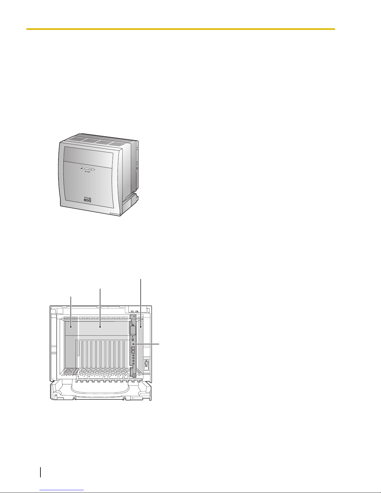
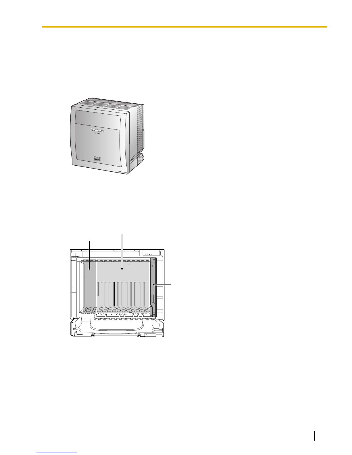
IPCEMPR Card
Free Slots
BUS-M Card Slot
PSU Slot
1.1.1 Basic System
1.1 System Construction
1.1.1 Basic System
Basic Shelf
The Basic Shelf contains an IPCEMPR card for controlling the PBX. To use the basic system, install a power
supply unit (PSU) in the PSU Slot and optional service cards in Free Slots. To expand to a multiple-shelf system,
you also need to install a BUS-M card in the BUS-M Card Slot.
Basic Shelf (KX-TDE600)
Construction of the Basic Shelf
Basic Shelf (KX-TDE600)
20 Installation Manual Document Version 2009-12
Page 21
BUS-S Card
Free Slots
PSU Slot
1.1.2 Expanded System
1.1.2 Expanded System
Expansion Shelf
Each Expansion Shelf contains a BUS-S card for connecting to the Basic Shelf. To use Expansion Shelf,
connect it to the Basic Shelf, and install a power supply unit (PSU) in the PSU Slot and optional service cards
in Free Slots. Up to 3 Expansion Shelves can be connected to the Basic Shelf.
Expansion Shelf (KX-TDE620)
Construction of an Expansion Shelf
Expansion Shelf (KX-TDE620)
Document Version 2009-12 Installation Manual 21
Page 22
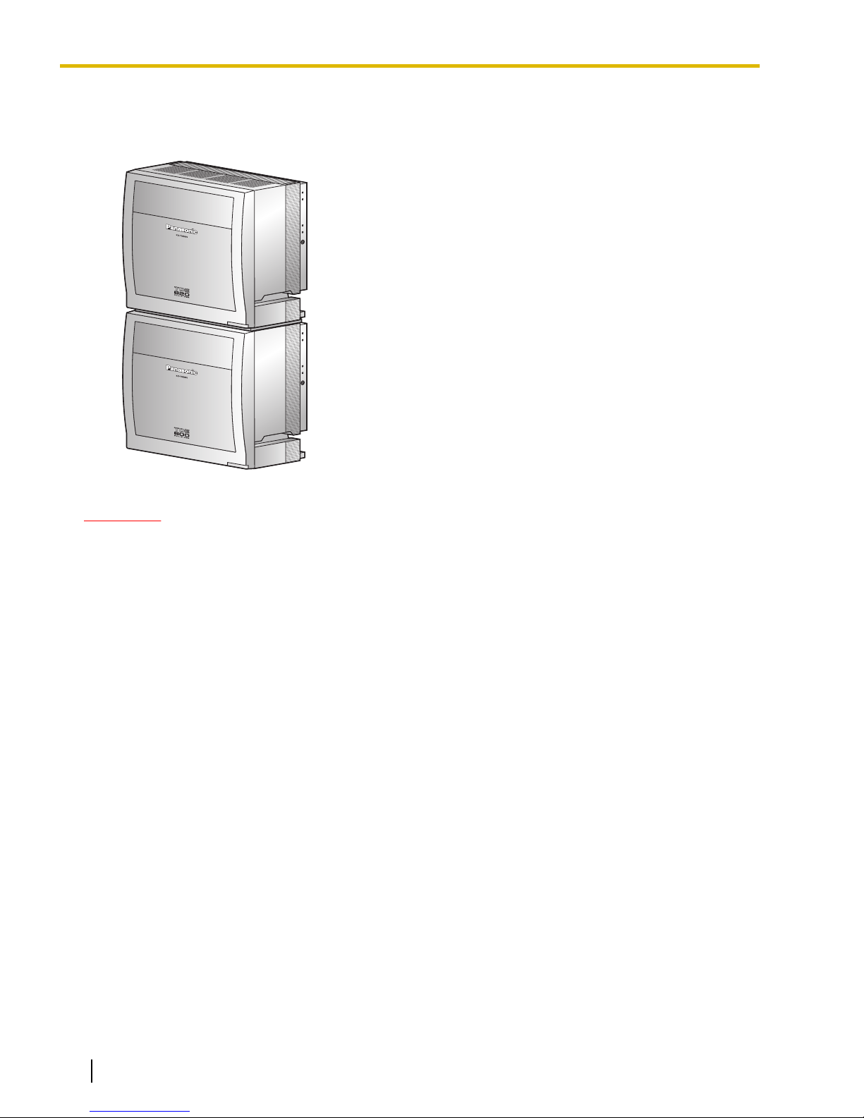
1.1.2 Expanded System
2-shelf System
Expanded system (Basic Shelf + 1 Expansion Shelf). Expansion Shelf 1 is mounted on the Basic Shelf.
CAUTION
If you are installing a 2-shelf system in an area prone to earthquakes, make sure to fix the system to the
wall using the wall brackets (supplied with an optional Mounting Kit).
22 Installation Manual Document Version 2009-12
Page 23
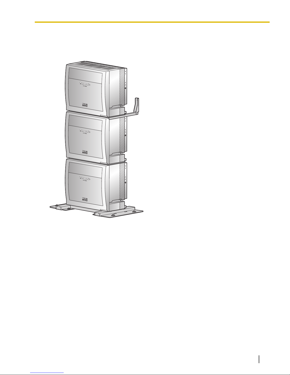
1.1.2 Expanded System
3-shelf System (Tower Type)
Expanded system (Basic Shelf + 2 Expansion Shelves). Expansion Shelves 1 and 2 are mounted on the Basic
Shelf. A Mounting Kit is required for the 3-shelf system.
Document Version 2009-12 Installation Manual 23
Page 24
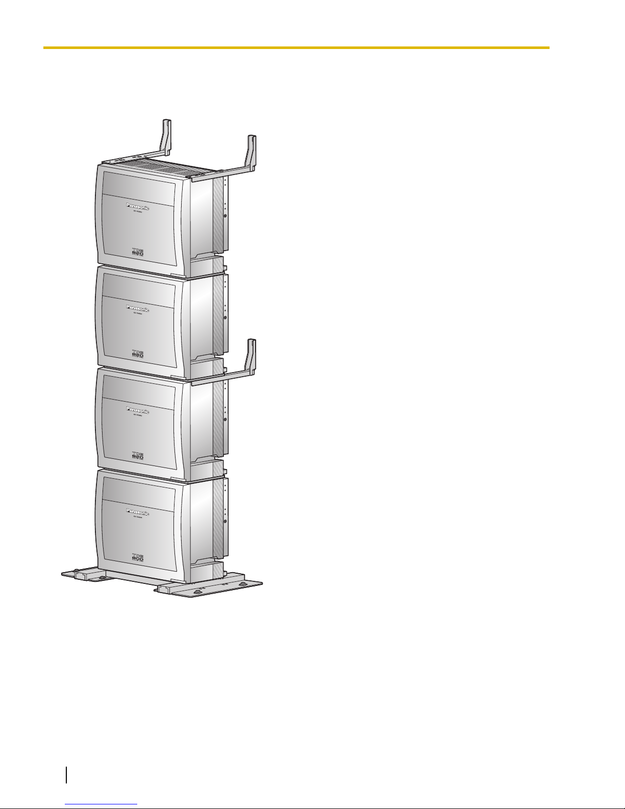
1.1.2 Expanded System
4-shelf System (Tower Type)
Fully expanded system (Basic Shelf + 3 Expansion Shelves). Expansion Shelves 1 to 3 are mounted on the
Basic Shelf. A Mounting Kit is required for the 4-shelf system.
24 Installation Manual Document Version 2009-12
Page 25
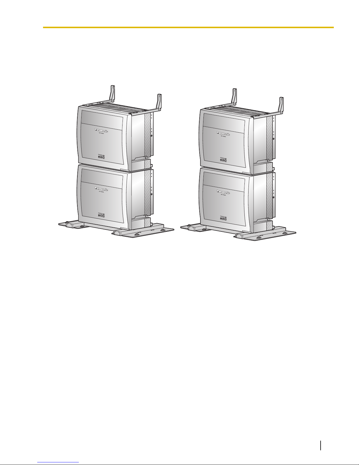
1.1.2 Expanded System
4-shelf System (Side-by-side Type)
When vertical space is limited, it is possible to install a fully expanded system (Basic Shelf + Expansion Shelf
1, and Expansion Shelf 2 + Expansion Shelf 3 ) in a side-by-side configuration. Expansion Shelf 1 is mounted
on the Basic Shelf, and Expansion Shelf 3 is mounted on Expansion Shelf 2. Installing the system using base
stands (supplied with an optional Mounting Kit) makes it easy to reinstall shelves in a different place.
Document Version 2009-12 Installation Manual 25
Page 26
Doorphone & Door Opener
BGM/Music On Hold (MOH)
Pager/
Speaker
Remote PC
PC
Printer
CO (Telephone Company) Lines
Analog/PRI/T1
PBX
Amplifier
External Sensor/
External Relay Device
KX-T7600 KX-T7600
Voice Processing
System
KX-T7636/
KX-T7633
Router
PC
CSPS
Wireless Phone
Fax Machine
PC
USB
APT
DPT
CTI Server
PC
PC
SLT
DSS Console
DSS Console
IP-PT
IP Softphone, CA
*
3
Client PC
SIP Extension
Private
IP Network
KX-DT346/
KX-DT343
PC
USB
KX-DT300 KX-DT300
ITSP
*
1
Network
DCE
*
2
(e.g., ADSL
Modem)
WAN
IP-CS PS
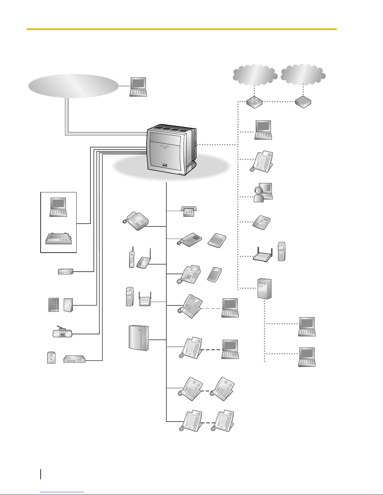
1.1.3 System Connection Diagram
1.1.3 System Connection Diagram
*1
ITSP: Internet Telephony Service Provider
*2
DCE: Data Circuit Terminating Equipment
*3
CA: Communication Assistant
26 Installation Manual Document Version 2009-12
Page 27
CSIF4
(KX-TDA0143)
CSIF8
(KX-TDA0144)
PSU-M/L
(KX-TDA0104/
KX-TDA0103)
EMSLC16
(KX-TDA6175)
EXT-CID
(KX-TDA0168)
ESLC16
(KX-TDA6174)
SLC8
(KX-TDA0173)
DSP16
(KX-TDE0110)
DSP64
(KX-TDE0111)
RMT
(KX-TDA0196)
DLC16
(KX-TDA0172)
DLC8
(KX-TDA0171)
DHLC8
(KX-TDA0170)
ESVM2
(KX-TDA0192)
IP-EXT16
(KX-TDA0470)
IP-GW4E
(KX-TDA0484)
IP-GW16
(KX-TDA0490)
EECHO16
(KX-TDA6166)
ECSLC24
(KX-TDA6178)
CSLC16
(KX-TDA0177)
IPCMEC
(KX-TDE0105)
IP-CS PS
CS PS
Doorphone & Door Opener
Station Message
Detail Recording (SMDR)
PC
SLT Wireless Phone Fax Machine
Mountable Equipment
Router
Radio
Amplifier Pager/Speaker
IPCEMPR
(Installed by default)
External Sensor/External Relay Device
PC
IP Softphone,
CA Client PC
LAN
CTI Server
IP-PT
SIP Extension
Telephone
Company
Private IP
Network
SLT
(DHLC
only)
Wireless Phone
(DHLC only)
Fax Machine
(DHLC only)
PT-interface CS
PS
Voice
Processing
System
APT
(DHLC only)
IP-PT
LAN
IP Softphone
Router
Private IP
Network
PC
DPT DSS
Console
KX-DT346/
KX-DT343/
KX-T7636/
KX-T7633 DPT
KX-DT300/
KX-T7600
DPT
KX-DT300/
KX-T7600
DPT
T1 Line
T1 Line
(Digital CO Line)
(Digital CO Line)
T1 Line
(Digital CO Line)
T1
(KX-TDA0187)
PRI23
(KX-TDA0290)
ISDN PRI Line
ISDN PRI Line
(Digital CO Line)
(Digital CO Line)
ISDN PRI Line
(Digital CO Line)
Analog
Analog
CO Line
CO Line
Analog
CO Line
ELCOT16
(KX-TDA6181)
CID8
(KX-TDA0193)
OPB3
(KX-TDA0190)
DPH4
(KX-TDA0161)
MSG4
(KX-TDA0191)
EIO4
(KX-TDA0164)
ESVM4
(KX-TDA0194)
Uninterruptible
Power Supply (UPS)
V-IPGW16
V-IPEXT32
V-SIPGW16
V-SIPEXT32
Virtual CO
Line Slot
Virtual
Extension Slot
ITSP
Network
DCE
(e.g., ADSL
Modem)
WAN
Router
V-IPCS4
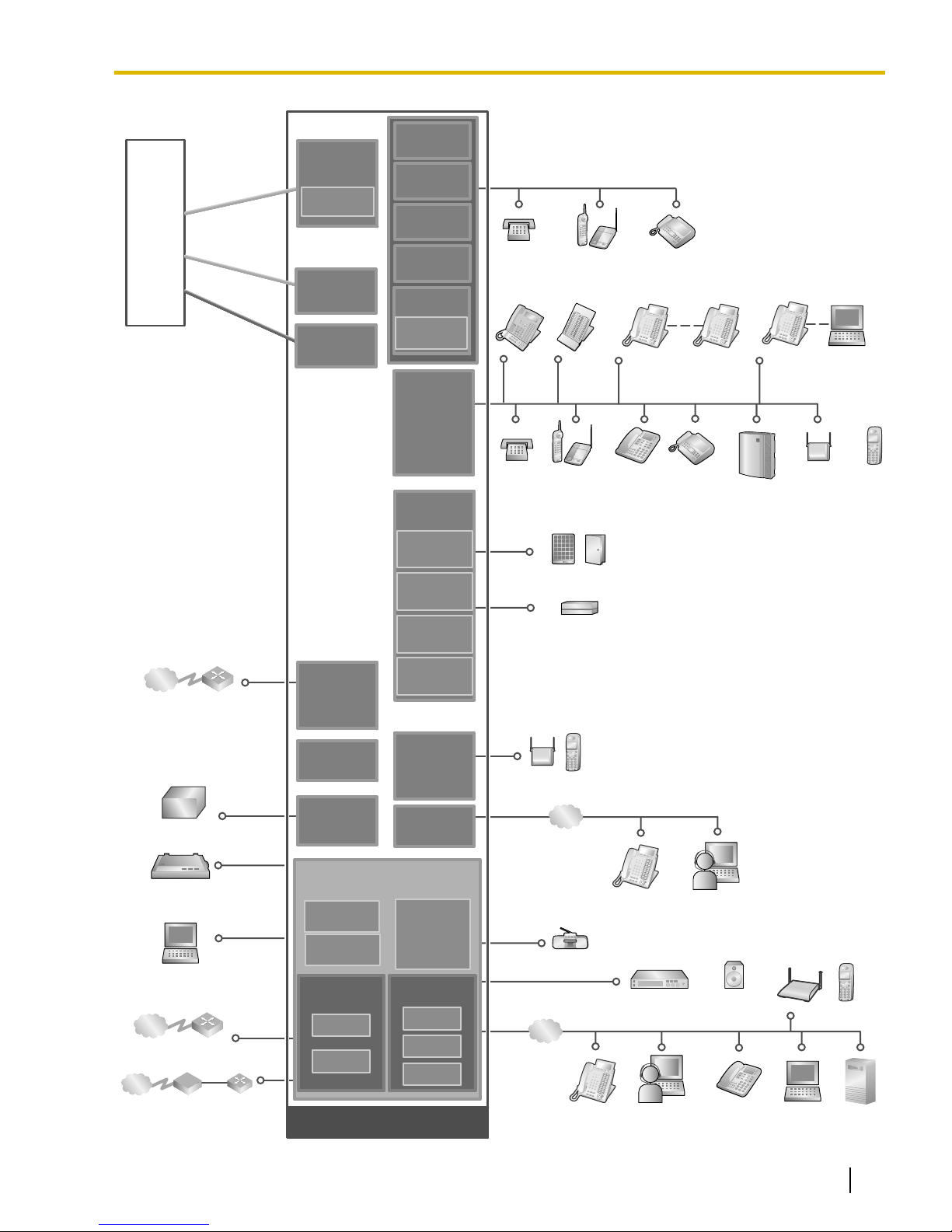
1.1.3 System Connection Diagram
Document Version 2009-12 Installation Manual 27
Page 28

1.2.1 Optional Equipment
1.2 Optional Equipment
1.2.1 Optional Equipment
Model No. Model Name Description
KX-TDE0105 Memory Expansion Card
(IPCMEC)
KX-TDE0110 16-Channel VoIP DSP Card
(DSP16)
KX-TDE0111 64-Channel VoIP DSP Card
(DSP64)
KX-TDA0103 L-Type Power Supply Unit
(PSU-L)
KX-TDA0104 M-Type Power Supply Unit
(PSU-M)
KX-TDA0143 4 Cell Station Interface Card
(CSIF4)
KX-TDA0144 8 Cell Station Interface Card
(CSIF8)
Memory expansion card to increase system data
storage space. To be mounted on the
IPCEMPR card.
16-channel digital signal processor card with a
4-Channel IP Trunk activation key and a
8-Channel IP Proprietary Telephone activation
key preinstalled. Compliant with ITU-T G.729A
and G.711 codec methods. To be mounted on
the IPCEMPR card.
64-channel digital signal processor card with four
4-Channel IP Trunk activation keys and four
8-Channel IP Proprietary Telephone activation
keys preinstalled. Compliant with ITU-T G.729A
and G.711 codec methods. To be mounted on
the IPCEMPR card.
Power Supply Unit. Total power output of 279 W.
Safety Class 1 compliant.
Power Supply Unit. Total power output of 140.4
W. Safety Class 1 compliant.
4-port CS interface card for 4 CSs.
8-port CS interface card for 8 CSs.
KX-TDA0161 4-Port Doorphone Card (DPH4) 4-port doorphone card for 4 doorphones and 4
door openers. To be mounted on the OPB3 card.
KX-TDA0164 4-Port External Input/Output Card
(EIO4)
KX-TDA0168 Extension Caller ID Card
(EXT-CID)
KX-TDA0170 8-Port Digital Hybrid Extension
Card (DHLC8)
KX-TDA0171 8-Port Digital Extension Card
(DLC8)
KX-TDA0172 16-Port Digital Extension Card
(DLC16)
KX-TDA0173 8-Port Single Line Telephone
Extension Card (SLC8)
28 Installation Manual Document Version 2009-12
4-port external input/output card. To be mounted
on the OPB3 card.
Sends Caller ID signals to extension ports. To be
mounted on the SLC8 card only.
8-port digital hybrid extension card for DPTs,
APTs, SLTs, DSS consoles, and PT-interface
CSs , with 2 power failure transfer (PFT) ports.
8-port digital extension card for DPTs, DSS
consoles, and PT-interface CSs.
16-port digital extension card for DPTs, DSS
consoles, and PT-interface CSs.
8-port extension card for SLTs with 2 power
failure transfer (PFT) ports.
Page 29

1.2.1 Optional Equipment
Model No. Model Name Description
KX-TDA0177 16-Port Single Line Telephone
Extension Card with Caller ID
16-port extension card for SLTs with Caller ID
(FSK) and 4 power failure transfer (PFT) ports.
(CSLC16)
KX-TDA0187 T-1 Trunk Card (T1) 1-port T1 CO line card. EIA/TIA standard
compliant.
KX-TDA0190 Optional 3-Slot Base Card (OPB3) Optional 3-slot base card for mounting a
maximum of 3 optional service cards from the
following: MSG4, DPH4 or EIO4 card.
KX-TDA0191 4-Channel Message Card (MSG4) 4-channel message card. To be mounted on the
OPB3 card.
KX-TDA0193 8-Port Caller ID Card (CID8) 8-port Caller ID signal type FSK/FSK (with Call
Waiting Caller ID [Visual Caller ID])/DTMF. To be
mounted on the ELCOT16 card.
KX-TDA0194 4-Channel Simplified Voice
Message Card (ESVM4)
4-channel simplified voice message card for
Built-in Simplified Voice Message feature. Also
supports MSG card features. To be mounted on
the OPB3 card.
KX-TDA0196 Remote Card (RMT) Analog modem card for remote communication
with the PBX. V90 support. To be mounted on
the IPCEMPR card.
KX-TDA0290 PRI Card (PRI23) 1-port ISDN Primary Rate Interface card (23B
channels). NI (North American standard ISDN
protocol) compliant.
KX-TDA0470 16-Channel VoIP Extension Card
(IP-EXT16)
16-channel VoIP extension card. Compliant with
Panasonic proprietary protocol, and ITU-T G.
729A and G.711 codec methods.
KX-TDA0484 4-Channel VoIP Gateway Card
(IP-GW4E)
4-channel VoIP gateway card. Compliant with
VoIP H.323 V.2 protocol, and ITU-T G.729A, G.
723.1, and G.711 codec methods.
KX-TDA0490 16-Channel VoIP Gateway Card
(IP-GW16)
16-channel VoIP gateway card. Compliant with
VoIP H.323 V.2 protocol, and ITU-T G.729A, G.
723.1, and G.711 codec methods.
KX-TDA6110 Bus Master Card (BUS-M) Optional shelf expansion card required when
mounting Expansion Shelves. To be installed in
the Basic Shelf only.
KX-TDA6111 Bus Master Expansion Card
(BUS-ME)
Optional shelf expansion card required when
mounting Expansion Shelf 2 or 3. To be mounted
on the BUS-M card installed in the Basic Shelf.
KX-TDA6166 16-Channel Echo Canceller Card
(EECHO16)
KX-TDA6174 16-Port Single Line Telephone
Extension Card (ESLC16)
16-channel card for echo cancellation during
conferences.
16-port extension card for SLTs with 4 power
failure transfer (PFT) ports.
Document Version 2009-12 Installation Manual 29
Page 30

1.2.1 Optional Equipment
Model No. Model Name Description
KX-TDA6175 16-Port Single Line Telephone
Extension with Message Lamp
Card (EMSLC16)
16-port extension card for SLTs with Message
Waiting Lamp control and 4 power failure transfer
(PFT) ports. Maximum power output of 145 V/
85 V for Message Waiting Lamp control.
KX-TDA6178 24-Port Single Line Telephone
Extension Card with Caller ID
(ECSLC24)
24-port extension card for SLTs with Caller ID
(FSK) and 4 power failure transfer (PFT) ports.
Can only be installed in shelves in which a
PSU-L is installed.
KX-TDA6181 16-Port Analog Trunk Card
(ELCOT16)
16-port analog CO line card with 4 power failure
transfer (PFT) ports.
KX-TDA6201 Mounting Kit Mounting Kit for expanding to a 3- or 4-shelf
system.
30 Installation Manual Document Version 2009-12
Page 31
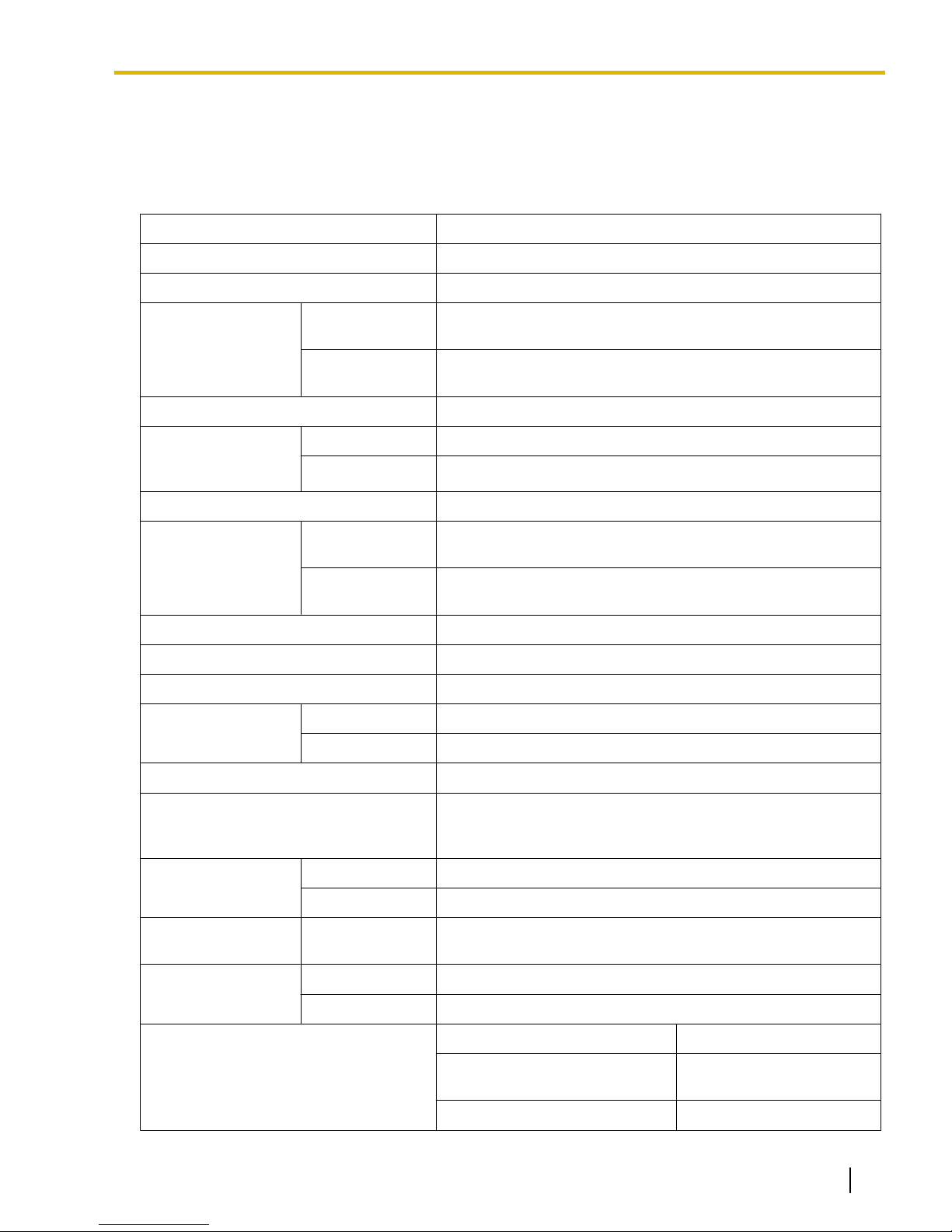
1.3.1 General Description
1.3 Specifications
1.3.1 General Description
Control Bus Original bus (16-bit, 8 MHz, 10 megabytes per second)
Communication Bus H.100 bus conformity (1024 time slots)
Switching Distributed Switching
Power Input PSU-M 100 V AC to 130 V AC; 2.5 A/200 V AC to 240 V AC; 1.4 A; 50
Hz/60 Hz
PSU-L 100 V AC to 130 V AC; 5.1 A/200 V AC to 240 V AC; 2.55 A;
50 Hz/60 Hz
Maximum Power Failure Tolerance
*1
300 ms
Power
Consumption (per
shelf)
Memory Backup Duration 7 years
Dialing CO Line Dial Pulse (DP) 10 pps, 20 pps
Mode Conversion DP-DTMF, DTMF-DP
Ring Frequency 20 Hz/25 Hz (selectable)
Central Office Loop Limit
Operating
Environment
Conference Call CO Line (per shelf)
Music on Hold (MOH) 2 ports (Level Control: -11 dB to +11 dB in 1 dB steps)
Paging Internal Level Control: -15 dB to +6 dB in 3 dB steps
With PSU-M 190 W; 2.5 A (at 120 V AC; 60 Hz)
With PSU-L 410 W; 5.1 A (at 120 V AC; 60 Hz)
Tone (DTMF) Dialing
Extension Dial Pulse (DP) 10 pps, 20 pps
Tone (DTMF) Dialing
1600 W maximum
Temperature 0 °C to 40 °C (32 °F to 104 °F)
Humidity 10 % to 90 % (non-condensing)
From 10 ´ 3-party conference call to 4 ´ 8-party conference call
MOH1: External Music Source port
MOH2: Selectable Internal/External Music Source port
External 2 ports (Volume Control: -15 dB to +15 dB in 1 dB steps)
Serial Interface
Port
RJ45 Port MNT Port 1 (for PC connection)
Extension Connection Cable SLT 1-pair wire (T, R)
Document Version 2009-12 Installation Manual 31
RS-232C 1 (maximum 115.2 kbps)
LAN Port 1 (for LAN connection)
DPT 1-pair wire (D1, D2) or
2-pair wire (T, R, D1, D2)
APT 2-pair wire (T, R, D1, D2)
Page 32
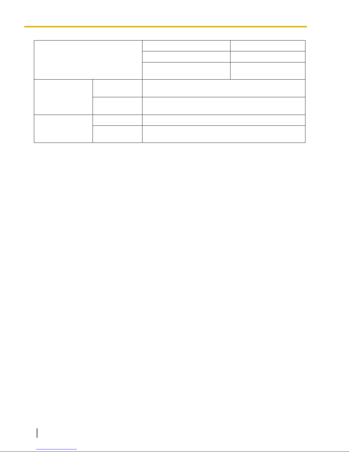
1.3.1 General Description
PT-interface CS 1-pair wire (D1, D2)
PT-interface CS (High-density) 4-pair wire (D1, D2)
DSS Console and Add-on Key
Module
Dimension Basic Shelf
430 mm (W) ´ 415 mm (H) ´ 270 mm (D)
(17-1/5 in ´ 16-3/5 in ´ 10-4/5 in)
Weight (when fully
mounted)
Expansion
Shelf
Basic Shelf Under 16 kg (35.2 lb)
Expansion
430 mm (W) ´ 415 mm (H) ´ 270 mm (D)
(17-1/5 in ´ 16-3/5 in ´ 10-4/5 in)
Under 16 kg (35.2 lb)
Shelf
*1
If tolerance may be exceeded, an Uninterruptible Power Supply (UPS) is recommended.
1-pair wire (D1, D2)
32 Installation Manual Document Version 2009-12
Page 33

1.3.2 Characteristics
1.3.2 Characteristics
Terminal Equipment Loop Limit
• PT: KX-DT300/KX-T7600 series DPT: 90 W; all other DPTs/APTs:
40 W
• SLT: 600 W including set
• Doorphone: 20 W
• CS: 130 W; PT-interface CS: 65 W
Minimum Leakage Resistance
Maximum Number of Extension
Instruments per Line
15 000 W minimum
1. for PT or SLT
2. by Parallel or eXtra Device Port connection of an APT/DPT and
an SLT
3. by Digital eXtra Device Port connection of 2 DPTs and an SLT
Ring Voltage 75 Vrms at 20 Hz/25 Hz depending on the Ringing Load
Central Office Loop Limit
Hookswitch Flash Timing Range 24 ms to 2032 ms
Door Opener Current Limit 24 V DC/30 V AC, 1 A maximum
External Relay Current Limit 24 V DC/30 V AC, 1 A maximum
External Sensor Current Limit Power to the external sensor is provided from the EIO4 card and must
1600 W maximum
be grounded through the EIO4 card. For the connection diagram, refer
to "3.9.3 EIO4 Card (KX-TDA0164)". The PBX detects input from the
sensor when the signal is under 100 W.
Paging Terminal Impedance
MOH (Music on Hold) Terminal
Impedance
600 W
10 000 W
Document Version 2009-12 Installation Manual 33
Page 34
ABC
D
1.3.3 System Capacity
1.3.3 System Capacity
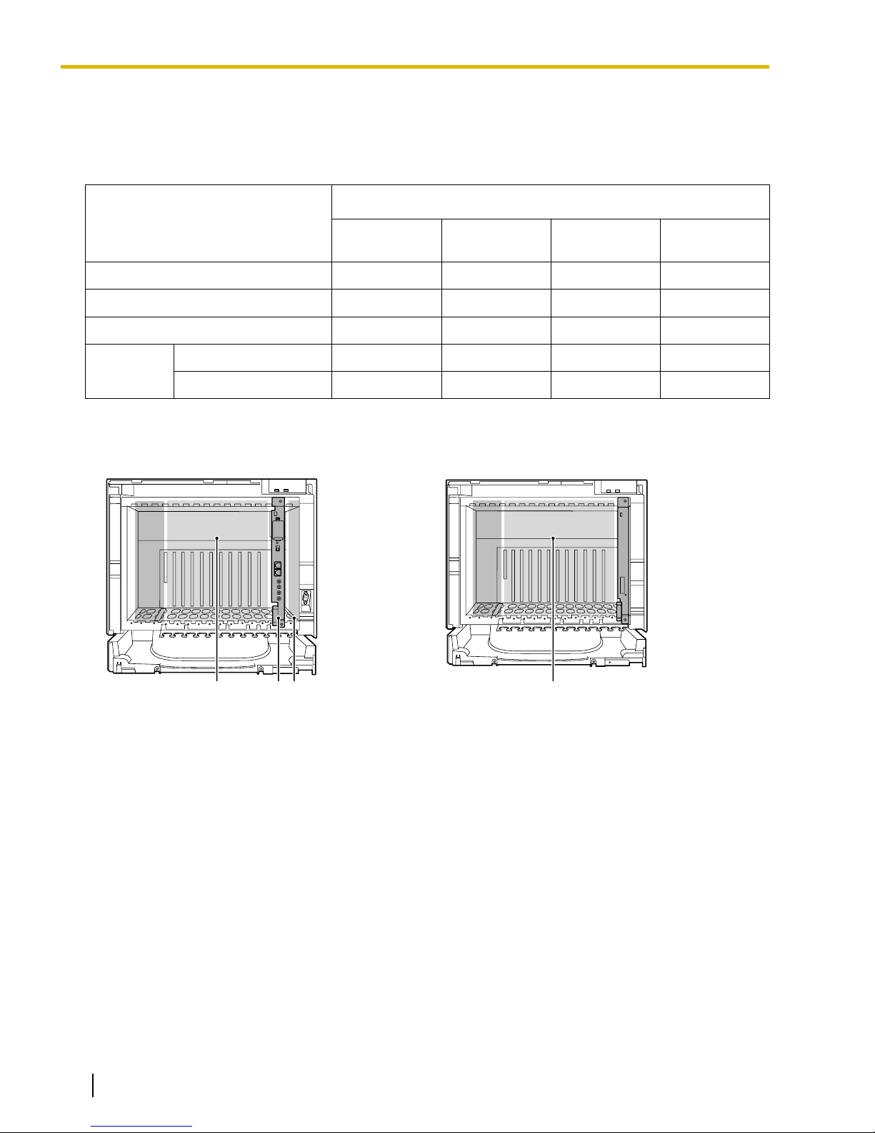
Type and Maximum Number of Slots
The PBX supports the following type and number of slots.
Maximum Number
Slot Type
Basic System
IPCEMPR Card Slot 1 1 1 1
BUS-M Card Slot 1 1 1 1
Free Slot 10 21 32 43
Virtual CO Line Slot 4 4 4 4
Virtual Slot
Virtual Extension Slot 4 4 4 4
Card Slots
Basic Shelf Expansion Shelf
2-shelf
System
3-shelf
System
4-shelf
System
A. Free Slots 1 to 10 (from the left)
B. IPCEMPR Card Slot
C. BUS-M Card Slot
D. Free Slots 1 to 11 (from the left)
34 Installation Manual Document Version 2009-12
Page 35
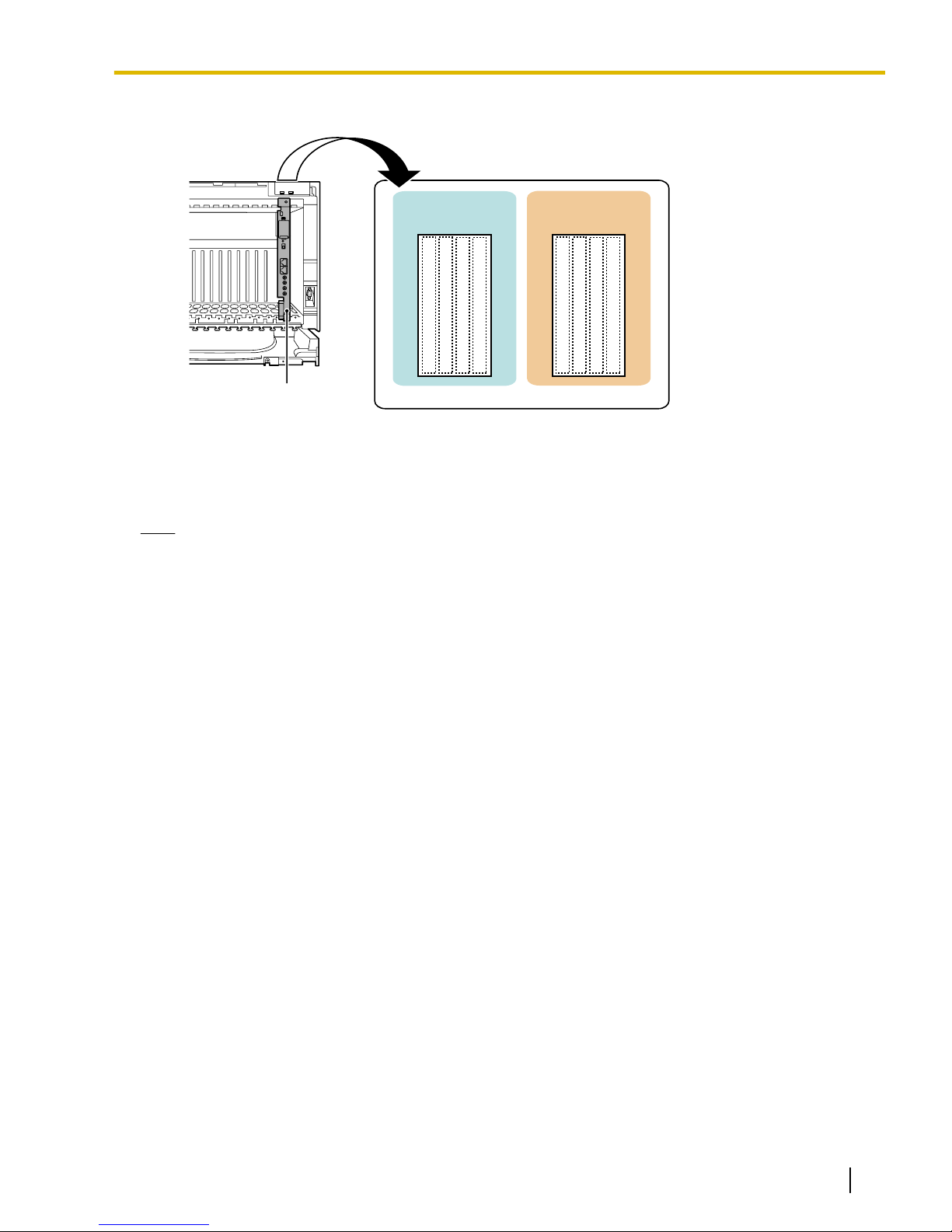
Virtual Slots of the IPCEMPR Card
IPCEMPR Card
Virtual Slots
Virtual CO
Line Slots
Virtual
Extension Slots
Maximum Optional Service Cards
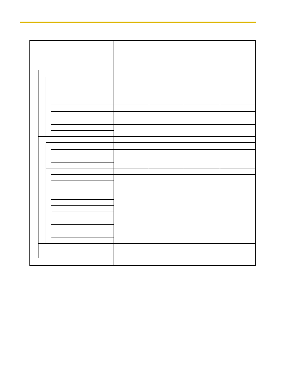
The following number of cards can be installed in the Free Slots or Virtual Slots of the PBX.
1.3.3 System Capacity
Note
• Any card that exceeds the capacity of the PBX will be ignored.
• When the PBX starts up with an invalid configuration, some cards will be ignored.
Document Version 2009-12 Installation Manual 35
Page 36
*1 *1
*3
Basic
System
11
22
14 40
44
10
30
5
40
10 40
V-IPGW16
ELCOT16
T1
PRI23
IP-GW4E
IP-GW16
V-IPEXT32
V-IPCS4
V-SIPEXT32
DHLC8
DLC8
DLC16
SLC8
CSLC16
ESLC16
ECSLC24
CSIF4
CSIF8
OPB3
IPCEMPR
CO Line Card
Card Type
Maximum Number
Virtual CO Line Card
Physical CO Line Card
To ta l
Virtual Extension Card
Physical Extension Card
One T1 or PRI23 card counts as 2 cards.
*1
*2
Extension Card
*1
2-shelf
System
4-shelf
System
3-shelf
System
1
1
24
34
4
4
2
2
10
20
30
40
IP-EXT16
EMSLC16
10
20
20
15
30
20
14
24
34
40
4
4
4
4
4
4
4
4
10
30
40
20
10
30
40
20
4
4
8
8
12
12
16
16
18 40 51 (43)29
*1
*2
Can only be installed in shelves in which a PSU-L is installed.
EECHO16
2
6
8
4
*1 *1 *1 *1
*3
The maximum number of CO line cards and extension cards is limited to 43.
Also, in this case, one T1 or PRI23 card counts as 1 card.
V-SIPGW16
2
2
22
1.3.3 System Capacity
Cards Installed in Free Slots or Virtual Slots
36 Installation Manual Document Version 2009-12
Page 37

Cards Mounted on Other Optional Service Cards
Maximum Number
Card Type
Basic System
DSP16
DSP64
IPCMEC
2-shelf
System
1
1
3-shelf
System
4-shelf
System
1.3.3 System Capacity
Mounted on
IPCEMPR
Card
RMT
1
CID8 20 40 60 80 ELCOT16
Card
EXT-CID
DPH4
10 20 30 40 SLC8 Card
4 8 12 16
MSG4
4 8 12 16
OPB3 Card
ESVM4
EIO4
BUS-ME
4 8 12 16
– 1 2 BUS-M Card
Document Version 2009-12 Installation Manual 37
Page 38
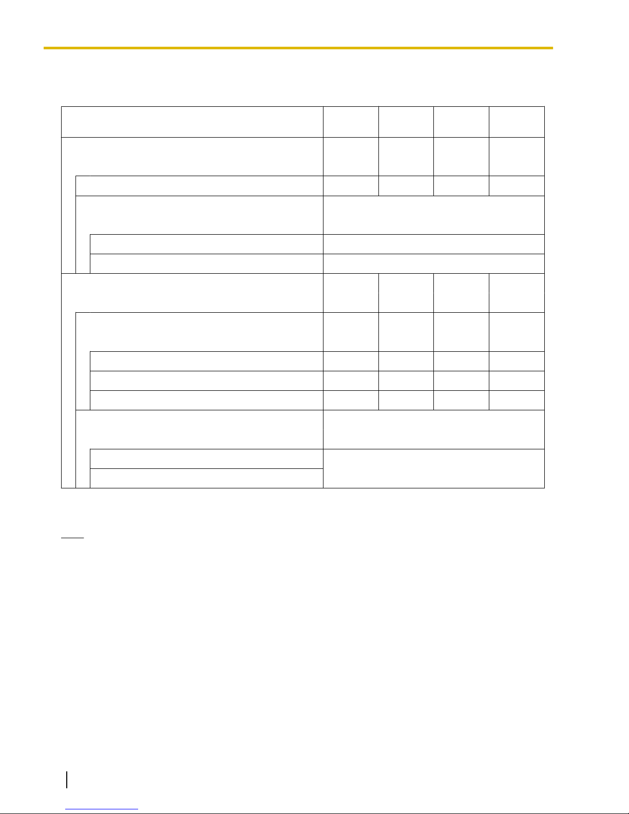
1.3.3 System Capacity
Maximum CO Lines and Extensions
The PBX supports the following number of CO lines and extensions.
Type
Basic
System
2-shelf
System
3-shelf
System
4-shelf
System
Total Number of CO Lines 224 384 544 640
CO Line (Physical CO Line Card) 160 320 480 640
CO Line (Virtual CO Line Card) 64
*1
H.323 CO Lines 32
SIP CO Lines 32
Total Number of Extensions 432 736 1008 1152
Extension (Physical Extension Card) 304 608 880 1120
PT 256 512 640
*2
640
SLT 240 480 720 960
PT and SLT 304 608 880 1120
Extension (Virtual Extension Card) 128
*1
*2
IP-PT and IP Softphone 128
SIP Extension
*1
Only 49 virtual CO line/extension card channels can be in use at any one time (except for peer-to-peer calls for IP extensions).
*2
The maximum number of PTs in the whole system is limited to 640.
Note
For non-peer-to-peer calls via the DSP card, calls cannot be made or received when all of the card's
resources are being used.
38 Installation Manual Document Version 2009-12
Page 39
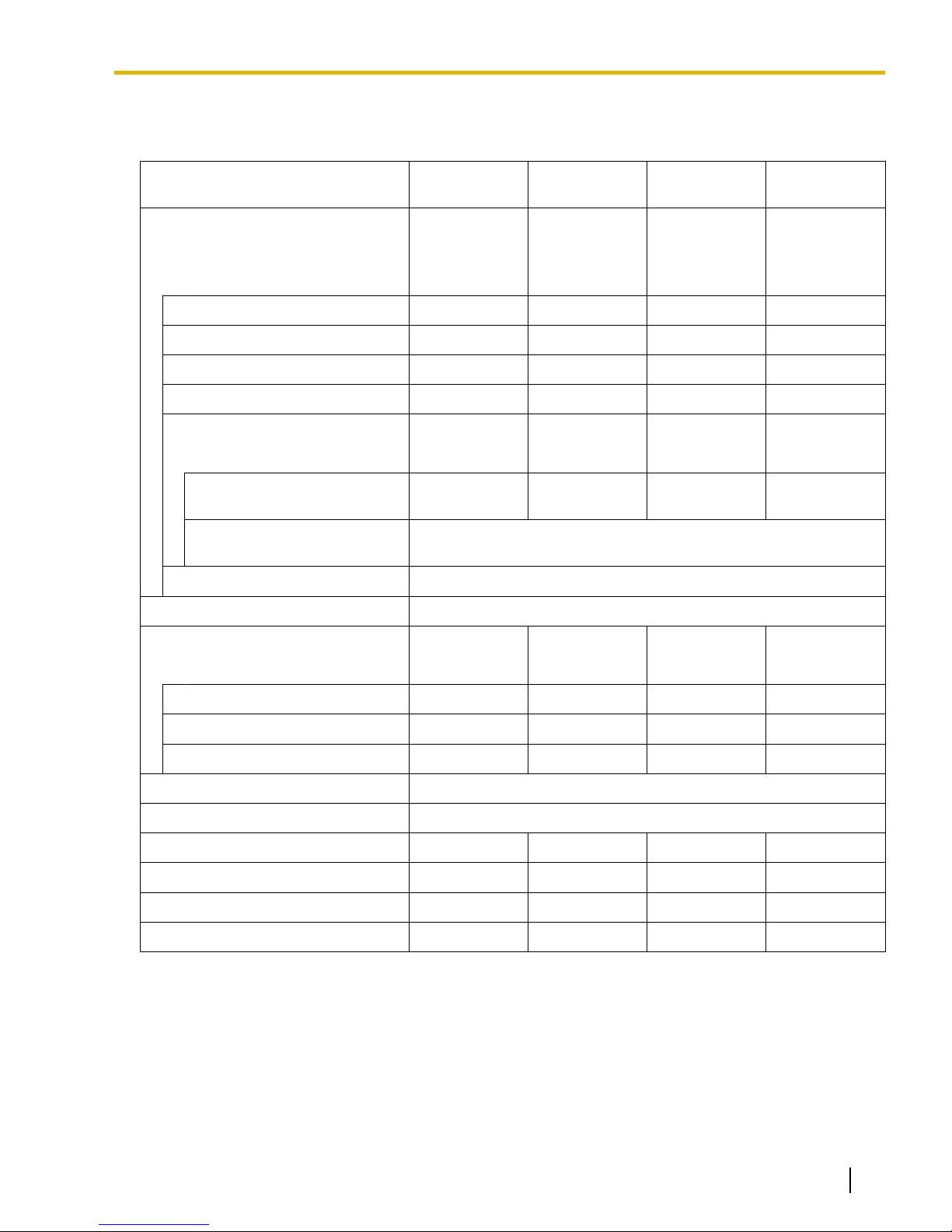
Maximum Terminal Equipment
The following number of items of terminal equipment can be supported by the PBX.
1.3.3 System Capacity
Terminal Equipment Type Basic System
2-shelf
System
3-shelf
System
4-shelf
System
Telephone 368 608 848 992
(using Digital XDP) (432)
*1
(736)
*1
(1008)
*1
(1152)
SLT 240 480 720 960
KX-DT300/KX-T7600 series DPT 256 512 640 640
Other DPT 128 256 384 512
APT 80 160 240 320
IP-PT 288 448 608 704
IP-PT*2 (supported by
160 320 480 640
IP-EXT16 card)
IP-PT*3 (supported by
128
*4
IPCEMPR card)
SIP Extension 128
DSS console 64
CS 32
*5
64
*5
96
*5
128
*1
*5
2- to 4- channel CS 32 64 96 128
High-density CS 16 32 48 64
IP-CS 16 16 16 16
PS 512
Voice Processing System (VPS)
*6
8
Doorphone 16 32 48 64
Door Opener 16 32 48 64
External Sensor 16 32 48 64
External Relay 16 32 48 64
*1
Even when Digital XDP is used, each shelf supports a maximum of 256 KX-DT300/KX-T7600 series DPTs.
*2
KX-NT300 series (except KX-NT366/KX-NT305), KX-NT265, and KX-NT136
*3
KX-NT400, KX-NT300 series, and KX-NT265 (software version 2.00 or later only)
*4
For the KX-NT400, the maximum number of extensions that can be connected to the PBX is 64.
*5
One high-density CS or IP-CS counts as 2 CSs for the total number of CSs.
*6
Only a single VPS can be connected to one optional service card.
Document Version 2009-12 Installation Manual 39
Page 40
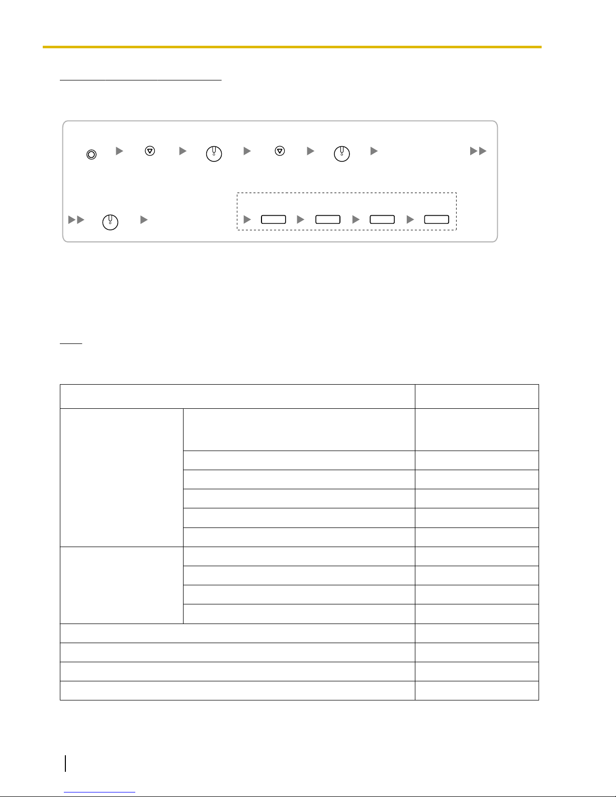
"AP Version".
Select
"Maintenance".
Software version
is displayed.
While starting up
Select
"Version display".
To exit the programming mode
PROGRAM
SP-PHONE
SP-PHONE
SP-PHONE
HOLD HOLD HOLD HOLD
1.3.3 System Capacity
Note for KX-NT265 IP-PT users
The supported card varies depending on the software version of your KX-NT265 IP-PT. To confirm the version,
follow the procedure below:
Power Supply Unit Selection for Each Shelf
The PBX needs a power supply unit (PSU) suitable for its configuration. For each shelf, calculate the load
figure from the type and number of items of equipment to be connected, and then determine the type of PSU
that will be required.
Note
Regardless of the total load figure, if a shelf contains an ECSLC24 card, the PSU-L must be installed.
Load Figure Calculation
Equipment Type
PT KX-DT300 series DPT/KX-DT300 series DSS
console/KX-T7600 series DPT/KX-T7600 series
DSS console
KX-T7560/KX-T7565 DPT 1
Other DPT/Other DSS console 4
APT 4
IP-PT 0
SIP Extension 0
Extension Card
*1
DHLC8 8
SLC8 8
ESLC16/CSLC16/EMSLC16 16
ECSLC24 24
Load Figure
1
CS (1 unit) 4
High-density CS (1 unit) 8
IP-CS (1 unit) 0
VPS (1 port) 1
*1
Only the extension cards that can support SLTs count for the load figures.
40 Installation Manual Document Version 2009-12
Page 41

1.3.3 System Capacity
PSU Capacity
Each PSU supports a different load figure.
PSU Type Maximum Load Figure
PSU-M 128
PSU-L 512
If the total load figure is greater than 128, you must install the PSU-L. If the total load figure is less than 128,
but you expect expansion in the future, it may be better to install the PSU-L instead of the PSU-M. There is no
harm in installing a PSU that is larger than is required for the current configuration.
Calculation Example
Equipment Type
Load Figure
KX-T7600 series DPT 48 units 48
Other DPT 4 units 16
ESLC16 1 card 16
EMSLC16 3 cards 48
VPS 8 ports 8
Total 136
The total load figure is 136. As this is between 128 and 512, you must install the PSU-L.
Document Version 2009-12 Installation Manual 41
Page 42

1.3.3 System Capacity
42 Installation Manual Document Version 2009-12
Page 43

Section 2
Activation Key Installation
This section describes information on activation keys,
including how to obtain an activation key and install it in
the SD Memory Card.
Document Version 2009-12 Installation Manual 43
Page 44

2.1.1 Activation Keys
2.1 Information about the Activation Keys
2.1.1 Activation Keys
To use IP CO lines and IP telephones on a private IP network using the IPCEMPR card or to upgrade the
software for enhanced features, you need the appropriate activation keys.
Type and Maximum Number of Activation Keys
The PBX supports the following type and number of activation keys:
Activation Key Type Description
2 IP Trunk
4 IP Trunk
*1
*1
1 IP Softphone/IP PT
4 IP Softphone/IP PT
8 IP Softphone/IP PT
16 IP Softphone/IP PT
1 IP PT
4 IP PT
8 IP PT
16 IP PT
Allows the use of 2 IP CO lines (H.
323/SIP).
Allows the use of 4 IP CO lines (H.
323/SIP).
Allows the use of 1 IP-PT/IP
*2
softphone.
Allows the use of 4 IP-PTs/IP
*2
softphones.
Allows the use of 8 IP-PTs/IP
*2
softphones.
Allows the use of 16 IP-PTs/IP
*2
softphones.
Allows the use of 1 IP-PT.
Allows the use of 4 IP-PTs.
Allows the use of 8 IP-PTs.
Allows the use of 16 IP-PTs.
Maximum
Number
32
16
128
32
16
8
128
32
16
8
Supported IP CO lines/
IP Telephones/CA
Users
64 IP CO lines (H.323/
SIP)
128 IP-PTs/IP softphones
128 IP-PTs
1 SIP Extension
4 SIP Extension
8 SIP Extension
16 SIP Extension
CA Basic 1user
CA Basic 5users
CA Basic 10users
CA Basic 40users
44 Installation Manual Document Version 2009-12
Allows the use of 1 SIP Extension.
Allows the use of 4 SIP Extensions.
Allows the use of 8 SIP Extensions.
Allows the use of 16 SIP
Extensions.
Allows the use of CA Basic for 1
user.
Allows the use of CA Basic for 5
users.
Allows the use of CA Basic for 10
users.
Allows the use of CA Basic for 40
users.
128
32
16
128 SIP Extensions
8
128 128 users
25 125 users
12 120 users
3 120 users
Page 45

2.1.1 Activation Keys
Activation Key Type Description
CA Basic 128users
CA Pro 1user
CA Pro 5users
CA Pro 10users
CA Pro 40users
CA Pro 128users
CA Supervisor 1user
Software Upgrade 01
*1
You need to set the number of the installed activation key to be used for H.323 CO lines through system programming. By default,
all the installed activation keys will be used for SIP CO lines.
*2
You can set how many IP softphones can be used with the installed activation keys through system programming. By default, only
IP softphones can be used with the installed activation keys.
Allows the use of CA Basic for 128
users.
Allows the use of CA PRO for 1
user.
Allows the use of CA PRO for 5
users.
Allows the use of CA PRO for 10
users.
Allows the use of CA PRO for 40
users.
Allows the use of CA PRO for 128
users.
Allows the use of CA ACD Monitor
for 1 ICD Supervisor.
Upgrades software to use
enhanced features.
Maximum
Number
1 128 users
128 128 users
25 125 users
12 120 users
3 120 users
1 128 users
4 4 users
1 -
Supported IP CO lines/
IP Telephones/CA
Users
Preinstalled Activation Keys in the DSP16/DSP64
The following type and number of activation keys are preinstalled on the DSP16/DSP64 card:
Card Type
DSP16
DSP64
4-Channel IP Trunk
8-Channel IP Proprietary
4-Channel IP Trunk
8-Channel IP Proprietary
Activation Key Supported IP CO lines/IP-PTs
1 4 IP CO lines (H.323/SIP)
Telephone
1 8 IP-PTs
4 16 IP CO lines (H.323/SIP)
Telephone
4 32 IP-PTs
Depending on the number of IP CO lines and IP-PTs to be used, you need to select either the DSP16 or
DSP64 card.
Additional Activation Keys in the SD Memory Card (Activation Key Files)
When the number of preinstalled activation keys on the DSP16/DSP64 card is not enough for the desired
configuration or when you wish to use enhanced features, additional activation keys in the form of activation
key files can be installed on the SD Memory Card.
The following type and number of additional activation keys can be installed on the SD Memory Card:
Document Version 2009-12 Installation Manual 45
Page 46

2.1.1 Activation Keys
Activation Keys for IP CO Lines
Model No. Activation Key Type
Maximum Number/Supported IP CO Lines
with DSP16 with DSP64
KX-NCS4102 2 IP Trunk 30
KX-NCS4104 4 IP Trunk 15 12
60 IP CO lines
(H.323/SIP)
24
48 IP CO lines (H.
323/SIP)
Activation Keys for IP Telephones
Maximum Number/Supported IP Telephones
Model No.
Activation Key Type
with DSP16 with DSP64
KX-NCS4201 1 IP Softphone/IP PT 120
KX-NCS4204 4 IP Softphone/IP PT 30
KX-NCS4208 8 IP Softphone/IP PT 15
KX-NCS4216 16 IP Softphone/IP PT 7
120 IP-PTs/IP
softphones
120 IP-PTs/IP
softphones
120 IP-PTs/IP
softphones
112 IP-PTs/IP
softphones
96
24
12
6
96 IP-PTs/IP
softphones
96 IP-PTs/IP
softphones
96 IP-PTs/IP
softphones
96 IP-PTs/IP
softphones
KX-NCS4501 1 IP PT 120 120 IP-PTs 96 96 IP-PTs
KX-NCS4504 4 IP PT 30 120 IP-PTs 24 96 IP-PTs
KX-NCS4508 8 IP PT 15 120 IP-PTs 12 96 IP-PTs
KX-NCS4516 16 IP PT 7 112 IP-PTs 6 96 IP-PTs
KX-NCS4701 1 SIP Extension 128
KX-NCS4704 4 SIP Extension 32 32
KX-NCS4708 8 SIP Extension 16 16
128 SIP
Extensions
128
128 SIP
Extensions
KX-NCS4716 16 SIP Extension 8 8
Activation Keys for CA Users
Model No.
Activation Key Type Maximum Number Supported CA Users
KX-NCS2101 CA Basic 1user 128 128 users
KX-NCS2105 CA Basic 5users 25 125 users
KX-NCS2110 CA Basic 10users 12 120 users
KX-NCS2140 CA Basic 40users 3 120 users
KX-NCS2149 CA Basic 128users 1 128 users
KX-NCS2201 CA Pro 1user 128 128 users
46 Installation Manual Document Version 2009-12
Page 47
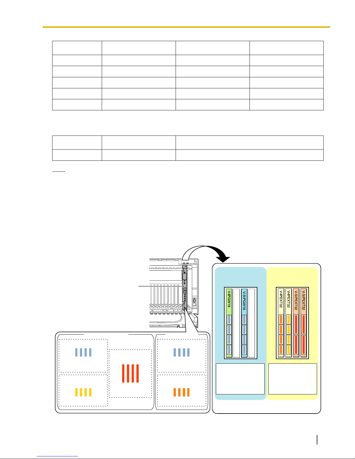
4-Channel IP Trunk
4-Channel IP Trunk
8-Channel IP
Proprietary Telephone
8-Channel IP Softphone/
IP Proprietary Telephone
16-Channel SIP
Extension
IPCEMPR Card
Virtual Slots
Virtual CO Line
Slots
Virtual Extension
Slots
SD Memory Card DSP64 Card
Total Total
32 IP-PTs32 IP softphones
64 SIP Extensions
16 IP CO lines
(H.323/SIP)
16 IP CO lines
(H.323/SIP)
16 H.323 CO lines
16 SIP CO lines
32 IP-PTs
32 IP softphones
64 SIP Extensions
2.1.1 Activation Keys
Model No. Activation Key Type Maximum Number Supported CA Users
KX-NCS2205 CA Pro 5users 25 125 users
KX-NCS2210 CA Pro 10users 12 120 users
KX-NCS2240 CA Pro 40users 3 120 users
KX-NCS2249 CA Pro 128users 1 128 users
KX-NCS2301 CA Supervisor 1user 4 4 users
Activation Keys for Software Upgrading
Model No.
Activation Key Type Maximum Number
KX-NCS4950 Software Upgrade 01 1
Note
• For information about how to obtain the additional activation keys, refer to "2.1.2 Activation Key Code
and Key Management System".
• For information about how to install the activation key files on the SD Memory Card, refer
to "2.1.3 Activation Key File".
Activation Key Installation Example
The following shows an example of when using 16 H.323 CO lines, 16 SIP CO lines, 32 IP-PTs, 32 IP
softphones, and 64 SIP Extensions on a private IP network using the IPCEMPR card.
Document Version 2009-12 Installation Manual 47
Page 48

2.1.2 Activation Key Code and Key Management System
2.1.2 Activation Key Code and Key Management System
To obtain additional activation keys, you need to purchase the appropriate activation key codes and access
the Key Management System. You can download the activation keys as an activation key file from the Key
Management System.
To download the activation keys, enter the MPR ID number shown on the IPCEMPR card in the PBX, and
activation key number and registration ID provided on each activation key code.
For information about the type of activation key codes available, refer to "Additional Activation Keys in the SD
Memory Card (Activation Key Files)".
Note
• You can only download the activation key file once using the activation key number and registration ID
provided on the activation key code.
• Up to 8 activation keys can be downloaded as one activation key file.
• Up to 100 activation key files can be installed in the SD Memory Card.
• It is possible to send the activation key file to a specified e-mail address at the same time as
downloading it to a PC.
• Make sure to backup the downloaded activation key files on your PC.
• In the event of a system malfunction, you need a temporary activation key for maintenance purposes.
The temporary activation key can only be used for a limited time period, and can be downloaded from
the Key Management System in the same way as downloading activation key files.
48 Installation Manual Document Version 2009-12
Page 49

2.1.3 Activation Key File
2.1.3 Activation Key File
The corresponding number of IP CO lines and IP telephones or enhanced features can be activated by installing
the downloaded activation key file(s) in the SD Memory Card of the IPCEMPR card using the Maintenance
Console.
Installing the Activation Key File in the SD Memory Card
Make sure to install the Maintenance Console on the PC in advance, and connect the PC to the PBX. For
details about the Maintenance Console, refer to "Section 4 Guide for the Maintenance Console".
1. Start the Maintenance Console from the Start menu on the PC.
2. From the Utility menu, select File Transfer PC to PBX (SD Card).
A dialog box will be displayed.
3. Select the file to upload.
A window showing the upload progress will be displayed.
While transferring files to the SD memory card, the PBX automatically renames them according to the
header information.
A message will be displayed when the transfer is complete.
4. Click OK.
5. Under Configuration, click Slot.
6. Click Activation Key.
7. For IP trunk activation key file(s), click Execute.
A confirmation message will be displayed. Click Yes.
Note
• It is necessary to restart the PBX to activate the Software Upgrade 01 activation key after performing
the procedure above. To restart the PBX, refer to "5.1.4 Using the Reset Button".
• For information about programming activation keys using the Maintenance Console, refer to "3.3 [1-1]
Slot—Activation Key" in the PC Programming Manual.
CAUTION
The activation key file can only be installed in the PBX with the MPR ID number entered when the activation
key file was downloaded. The activation key file cannot be reissued unless the IPCEMPR card crashes.
Document Version 2009-12 Installation Manual 49
Page 50

2.1.3 Activation Key File
50 Installation Manual Document Version 2009-12
Page 51

Section 3
Installation
This section describes the procedures to install the
PBX. Detailed instructions for planning the installation
site, installing the shelves and optional service cards,
and cabling of peripheral equipment are provided.
Further information on system expansion and peripheral
equipment installation is included.
Document Version 2009-12 Installation Manual 51
Page 52

3.1.1 Before Installation
3.1 Before Installation
3.1.1 Before Installation
Please read the following notes concerning installation and connection before installing the PBX and terminal
equipment.
Be sure to comply with all applicable laws, regulations, and guidelines.
Safety Installation Instructions
WARNING
When installing telephone wiring, basic safety precautions should always be followed to reduce the
risk of fire, electric shock and injury to persons, including the following:
• Never install telephone wiring during a lightning storm.
• Never install telephone jacks in wet locations unless the jack is specifically designed for wet
locations.
• Never touch uninsulated telephone wires or terminals unless the telephone line has been
disconnected at the network interface.
• Use caution when installing or modifying telephone lines.
• Anti-static precautions should be taken during installation.
Installation Precautions
The PBX is made for both floor standing and wall mounting, and should be installed in a location where it is
accessible for inspections and maintenance.
To prevent malfunction, noise, or discoloration, follow the instructions below:
Do not install the system in the following locations:
WARNING
• Areas where shocks or vibrations are frequent or strong. Such activity may lead to the product
falling over and causing injury, or may impair the product's performance.
• Areas with high amounts of dust. High amounts of dust can lead to fire or electric shock, and
impair the performance of the product.
CAUTION
• In direct sunlight and hot, cold, or humid places. (Temperature range: 0 °C to 40 °C [32 °F to 104 °F])
• Areas where sulfuric gases may be present, such as near thermal springs.
• Near devices that generate high frequencies, such as sewing machines or electric welders.
• Locations where other objects will obstruct the area around the PBX. Be especially careful to leave at
least 20 cm (8 in) of space above and 10 cm (4 in) to the sides of the PBX for ventilation.
Notice
Do not install the system in the following locations:
• On or near computers, telexes, or other office equipment, as well as microwave ovens or air
conditioners. (It is preferable not to install the system in the same room as the above equipment.)
• Within 1.8 m (6 ft) of radios and televisions. (Both the PBX and PTs should be at least 1.8 m (6 ft) away
from such devices.)
Do not perform the following:
• Do not block the openings of the PBX.
52 Installation Manual Document Version 2009-12
Page 53

• Do not stack up the optional service cards.
Wiring Precautions
Be sure to follow these instructions when wiring the unit:
WARNING
• Do not run unshielded telephone cables near AC power cables, computer cables, AC power
sources, etc. When running cables near other noise-generating devices or cables, use shielded
telephone cables or shield the telephone cables with metal tubing.
• If cables are run on the floor, use protectors to prevent the cables from being stepped on. Avoid
running cables under carpets.
• For safety purposes this unit is equipped with a grounded plug. If you do not have a grounded
outlet, please have one installed. Do not bypass this safety feature by tampering with the plug.
CAUTION
• Avoid using the same AC outlet for computers, telexes, and other office equipment, as noise generated
by such equipment may hamper system performance or interrupt the system.
• Unplug the system from its power source when wiring, and plug the system back in only after all wiring
is completed.
• CO lines should be installed with surge protectors. For details, refer to "3.2.16 Surge Protector
Installation".
3.1.1 Before Installation
Notice
• Use 2-pair telephone cables when connecting PTs.
Use 1-pair telephone cables when connecting SLTs, data terminals, answering machines, computers,
Voice Processing Systems, etc.
• Mis-wiring may cause the PBX to operate improperly. Refer to "Section 3 Installation" when wiring
the system.
• If an extension does not operate properly, disconnect the telephone from the extension line and connect
it again, or turn off the PBX using the power switch, then turn it on again.
• Use twisted pair cable for CO line connection.
• To prevent signal noise from interfering with the performance of the product, do not run unshielded
telephone cables near AC power cables, computer cables, AC power sources, etc. When running
cables near other noise-generating devices or cables, use shielded telephone cables or shield the
telephone cables with metal tubing.
• To assure good quality telephone connection, it is recommended new and modifications to existing
installation of customer premise wiring shall use solid twisted pair copper conductors with minimum 24
gauge that comply with the electrical specifications for Category 3 wiring as detailed in ANSI/EIA/
TIA-570A Building Wiring Standards.
Document Version 2009-12 Installation Manual 53
Page 54
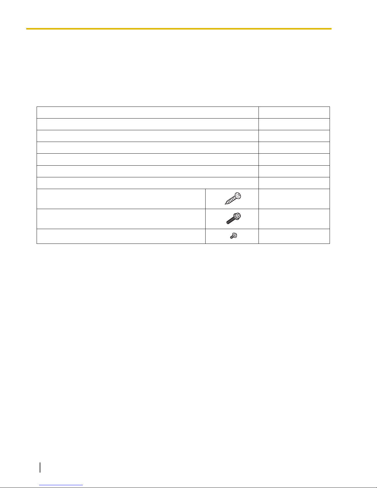
3.2.1 Unpacking
3.2 Installation of the PBX
3.2.1 Unpacking
Supplied Items for the Basic Shelf (KX-TDE600)
Unpack the box and check the items below:
Main Unit 1
Ferrite Core (for the IPCEMPR card) 2
Metal Bracket 1
Anchor Plug 4
Fan Guard 2
Mini Plug (for pager and music source) 4
SD Memory Card 1
Screw A 4
Screw B 6
Screw C 2
54 Installation Manual Document Version 2009-12
Page 55
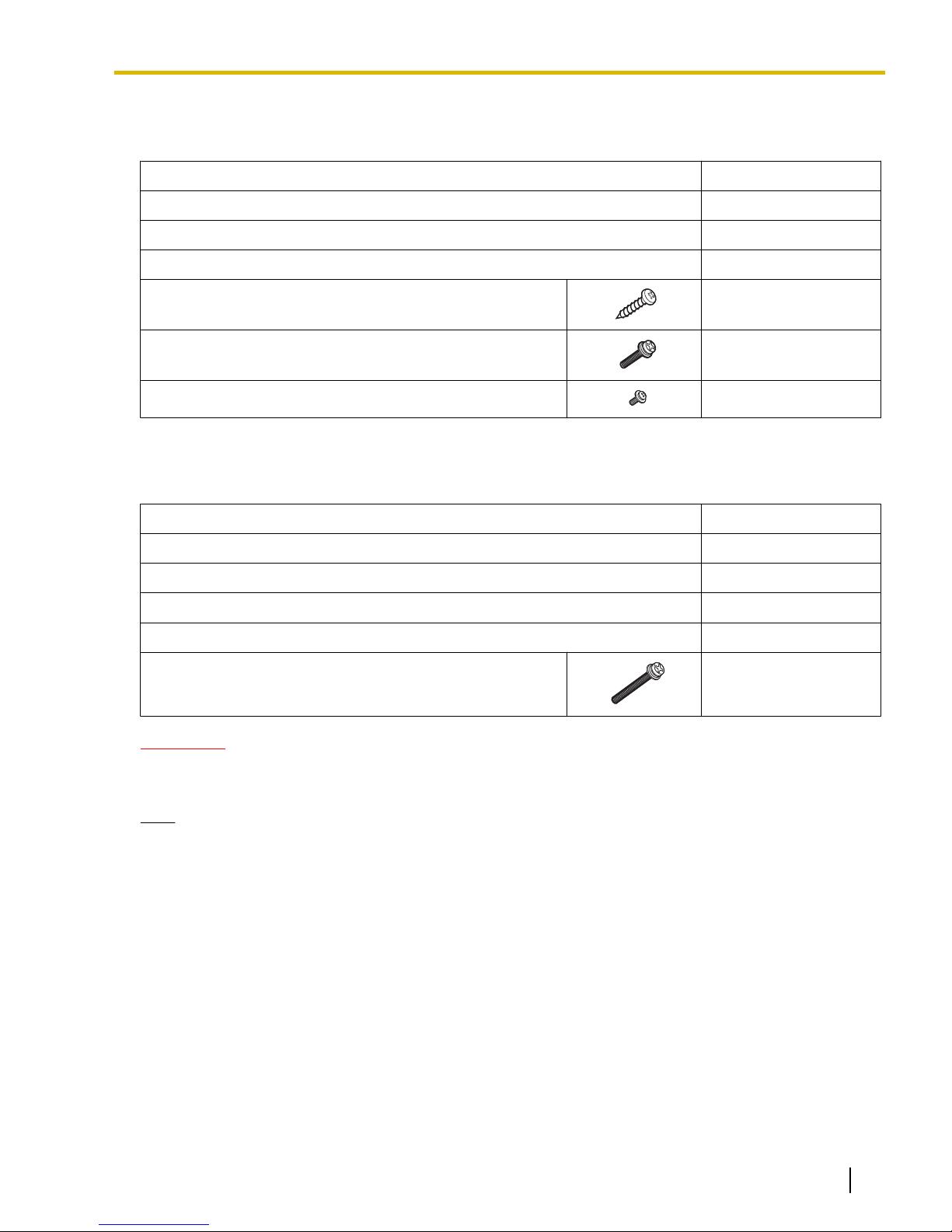
Supplied Items for an Expansion Shelf (KX-TDE620)
Unpack the box and check the items below:
Main Unit 1
Metal Bracket 1
Anchor Plug 4
Fan Guard 2
Screw A 4
Screw B 6
Screw C 2
Supplied Items for the Mounting Kit (KX-TDA6201)
Unpack the box and check the items below:
3.2.1 Unpacking
Wall Bracket (Right) 2
Wall Bracket (Left) 2
Base Stand 4
Support Bracket 4
Washer 16
Screw D 8
CAUTION
If you are installing a multiple-shelf system in an area prone to earthquakes, make sure to fix the system
to the wall using the wall brackets.
Note
When installing the Mounting Kit, it is necessary to use the screws (A) and anchor plugs supplied with the
Basic Shelf or Expansion Shelf.
Document Version 2009-12 Installation Manual 55
Page 56
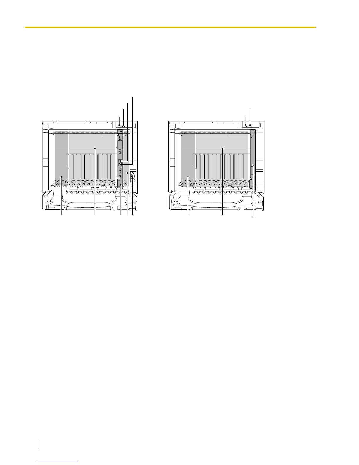
A
B
F
C
A
B
GEJKHE
D
I
3.2.2 Names and Locations
3.2.2 Names and Locations
Inside View
Basic Shelf (KX-TDE600) Expansion Shelf (KX-TDE620)
A. RUN Indicator
B. ALARM Indicator
C. MNT Port
D. LAN Port
E. PSU Slot
F. Free Slots 1 to 10 (from the left)
G. IPCEMPR Card
H. BUS-M Card Slot
I. RS-232C Port
J. Free Slots 1 to 11 (from the left)
K. BUS-S Card
56 Installation Manual Document Version 2009-12
Page 57
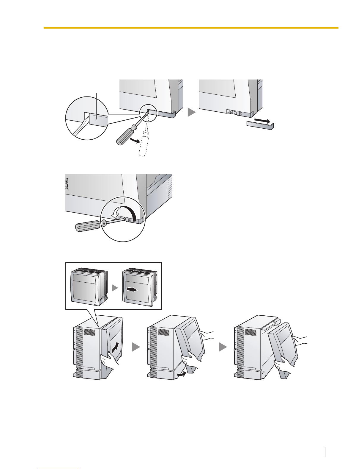
Screw Cover
3.2.3 Opening/Closing the Front Cover
3.2.3 Opening/Closing the Front Cover
Opening the Front Cover
1. Insert a flathead screwdriver into the opening (on the left of the screw cover) and unlatch the screw cover.
2. Turn the screw counterclockwise to loosen.
3. Slide the front cover to the right until it stops, then lift the front cover.
Document Version 2009-12 Installation Manual 57
Page 58
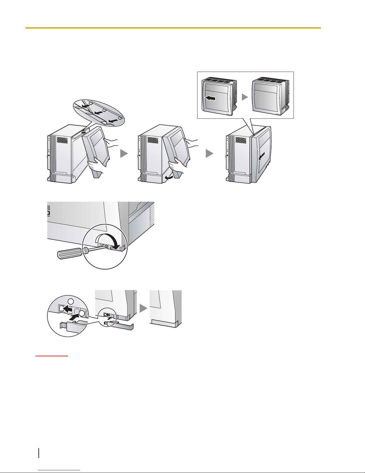
1
2
3.2.3 Opening/Closing the Front Cover
Closing the Front Cover
1. Hook the front cover onto the shelf (line up the protrusions on the cover with the receptacles on the shelf).
Then slide the front cover to the left until it locks.
2. Turn the screw clockwise to tighten.
3. Secure the screw cover.
CAUTION
• For safety reasons, close the front cover and tighten the screw before operating the PBX.
• Do not forget to tighten the screw before securing the screw cover.
58 Installation Manual Document Version 2009-12
Page 59
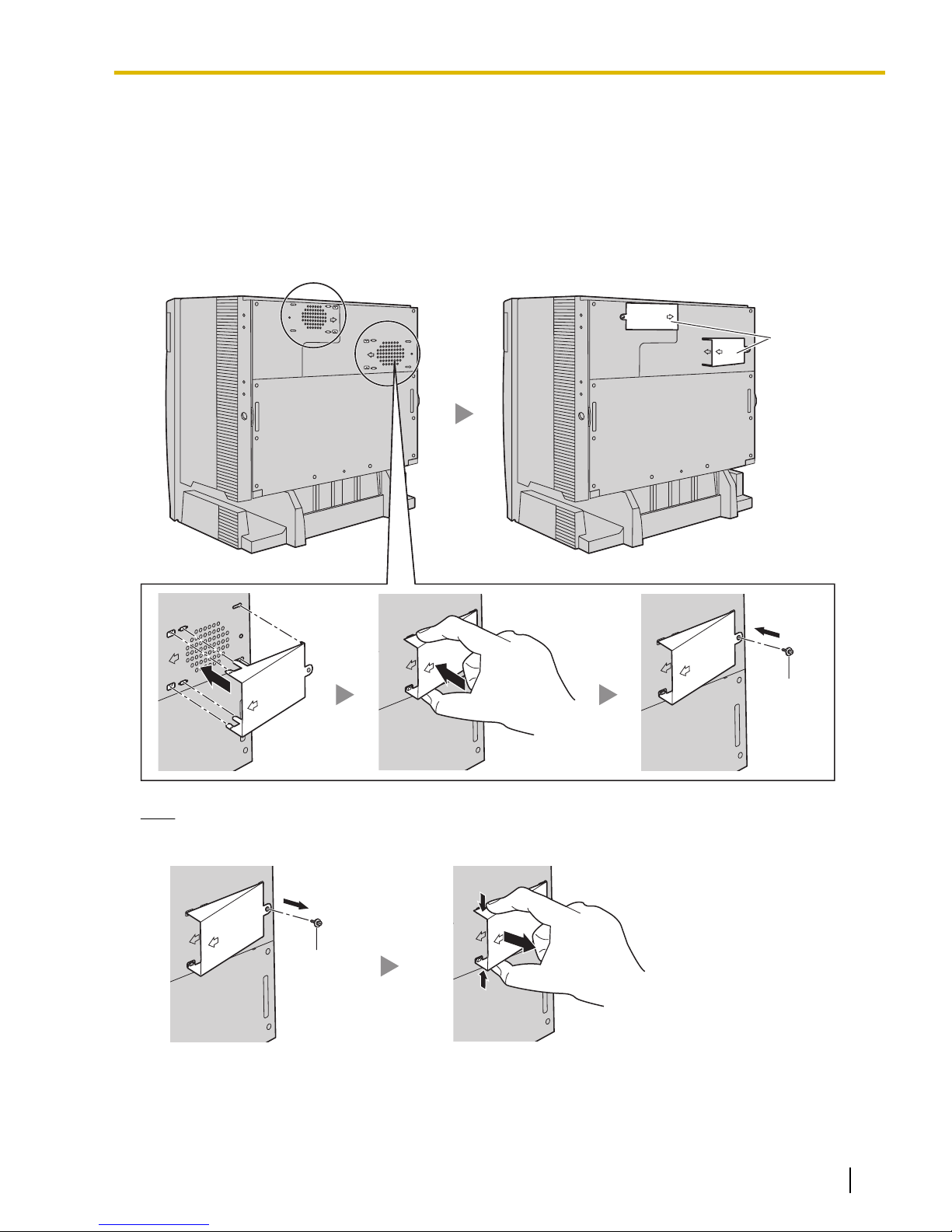
3.2.4 Attaching Fan Guards
Fan Guards
Screw (C)
Screw (C)
Attaching Fan Guards
Fan Guards (supplied with the shelf) must be attached using the screws (C) when:
• installing a multiple-shelf system,
• mounting the shelf on the wall, or
• installing the shelf near the wall
to protect the air vents on the back of the shelf.
3.2.4 Attaching Fan Guards
Note
If you need to remove the Fan Guard:
Document Version 2009-12 Installation Manual 59
Page 60
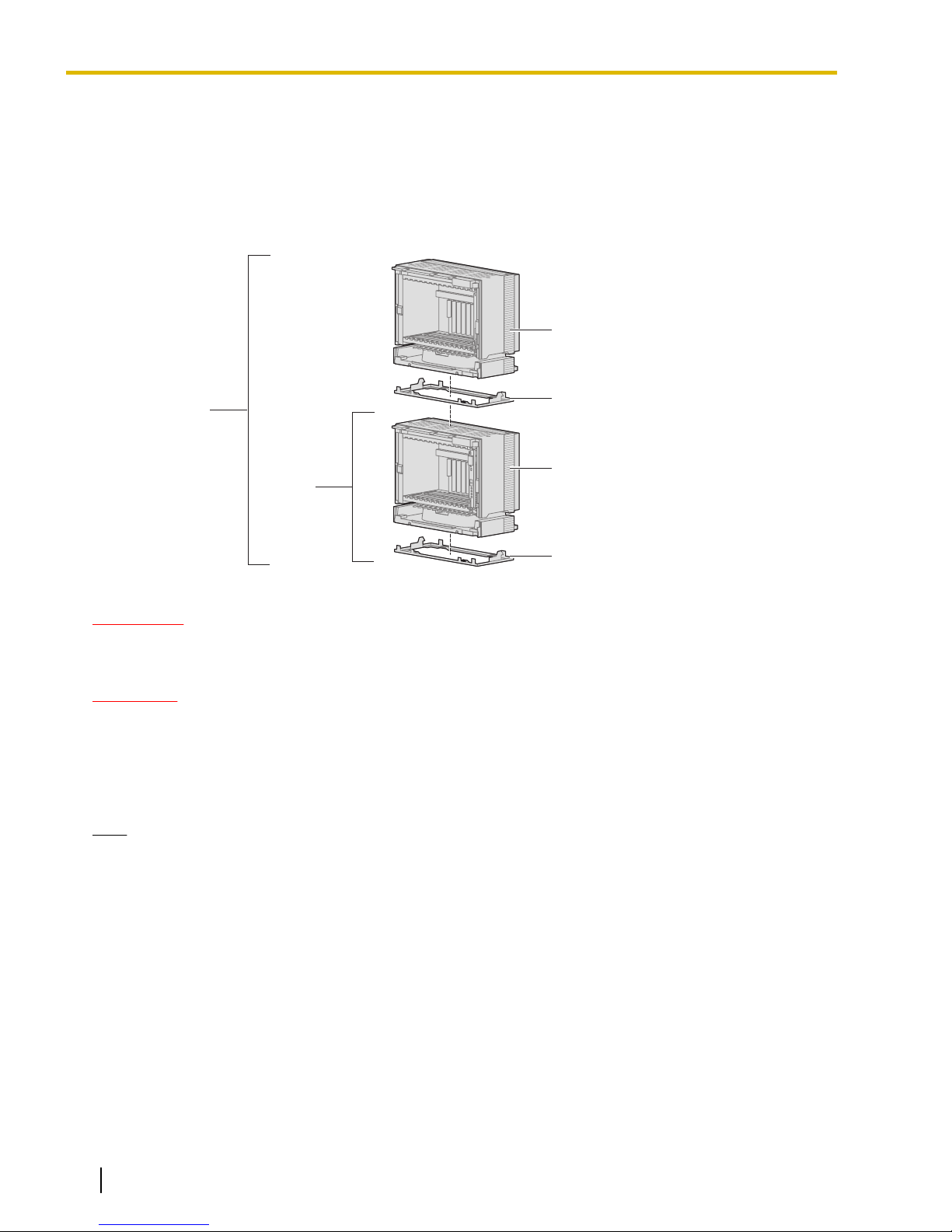
Basic
System
Expansion Shelf 1
Basic Shelf
Metal Bracket
Metal Bracket
2-shelf
System
3.2.5 Installation of Basic System or 2-shelf System (Floor Standing)
3.2.5 Installation of Basic System or 2-shelf System (Floor
Standing)
The PBX can be expanded to a 2-shelf system by mounting an Expansion Shelf on the Basic Shelf.
Construction of Basic System or 2-shelf System
WARNING
CAUTION
Note
Be careful not to drop any components. Dropping components may damage them or cause an
injury.
• Do not block the openings of the shelf. Allow space of at least 10 cm (4 in) at the sides of the shelf,
and 20 cm (8 in) above the top-mounted shelf.
• Make sure that the surface behind the shelf is flat and free of obstacles, so that the openings on the
back of the shelf will not be blocked.
• Make sure that the surface behind the shelf is not made of wood.
• Make sure to remove the front cover from each shelf before installing the shelves (refer
to "3.2.3 Opening/Closing the Front Cover").
• Do not install any optional service cards or a PSU in the shelves before installation.
60 Installation Manual Document Version 2009-12
Page 61
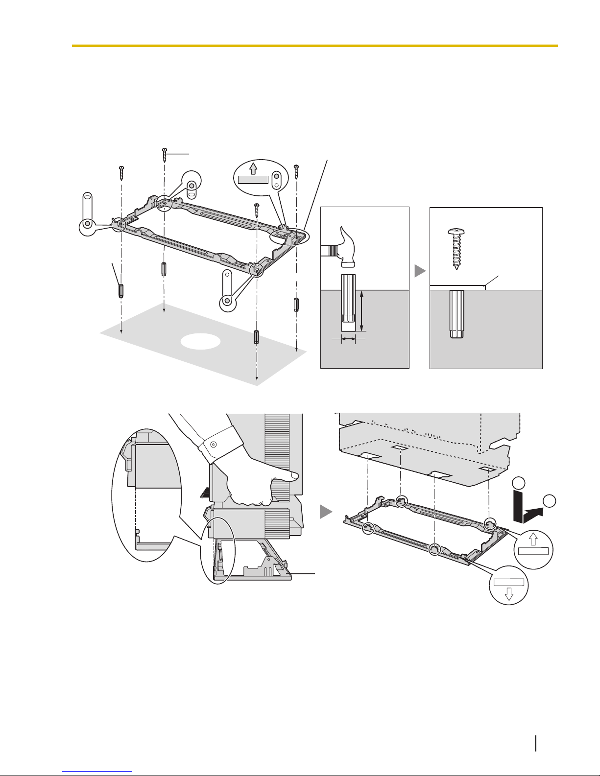
TOP
30 mm
(1-3/16 in)
8 mm
(5/16 in)
Floor
Screw (A) Metal Bracket
Anchor
Plug
Anchor
Plug
Hammer
Metal
Bracket
Screw (A)
FRONT
TOP
1
2
Metal Bracket
3.2.5 Installation of Basic System or 2-shelf System (Floor Standing)
Installing the Basic Shelf
For the basic system, install the metal bracket (supplied with the Basic Shelf) on the floor first. Then, attach
the Basic Shelf to the metal bracket.
1. Install 4 anchor plugs on the floor, using the metal bracket as a template. Fix the metal bracket in place
with 4 screws (A).
2. Lift the Basic Shelf, attach it to the metal bracket, and slide it backwards until it locks.
Document Version 2009-12 Installation Manual 61
Page 62
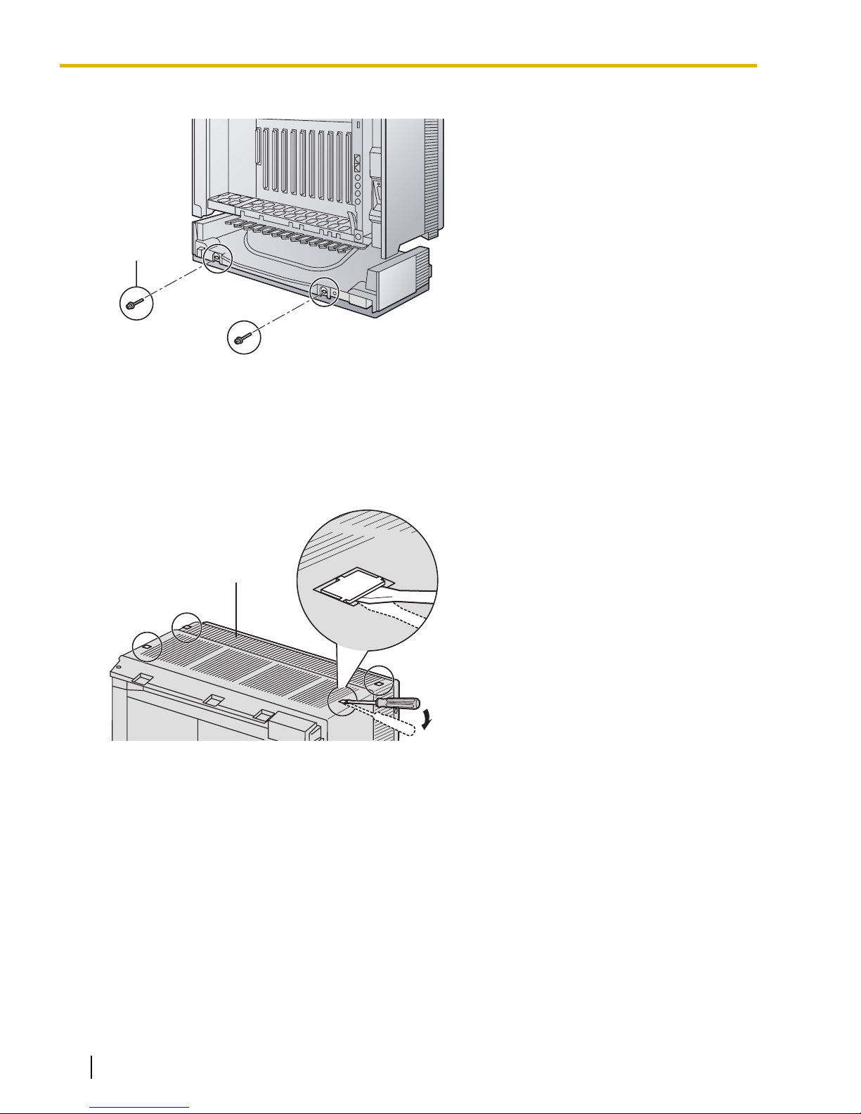
Screw (B)
Basic Shelf
3.2.5 Installation of Basic System or 2-shelf System (Floor Standing)
3. Secure the Basic Shelf to the metal bracket with 2 screws (B).
Installation of the basic system is complete. If you are installing a 2-shelf system, follow the procedure below.
Mounting Expansion Shelf 1
For the 2-shelf system, attach the metal bracket (supplied with the Expansion Shelf 1) to the Basic Shelf first.
Then, mount Expansion Shelf 1 on the Basic Shelf.
1. Remove the 4 tabs on the top cover of the Basic Shelf, by using a flathead screwdriver, as shown below.
62 Installation Manual Document Version 2009-12
Page 63
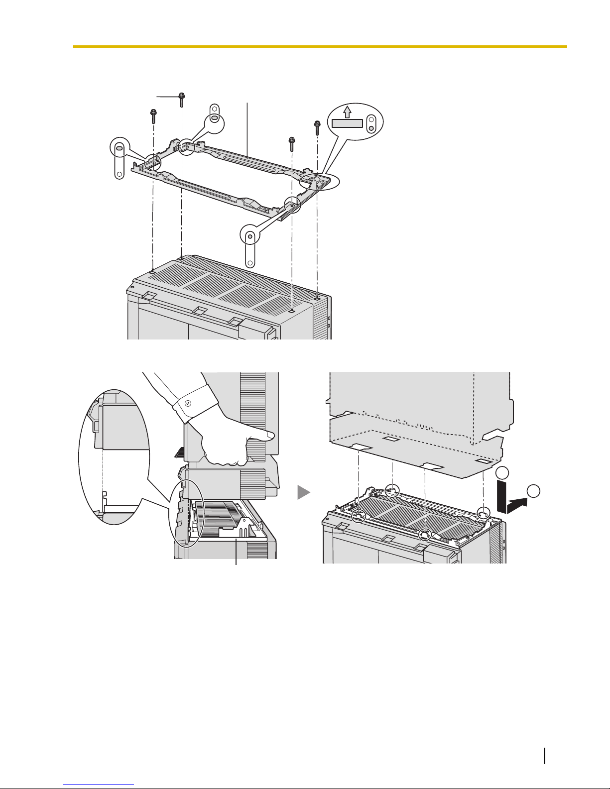
TOP
Screw (B)
Metal Bracket
1
2
Metal Bracket
3.2.5 Installation of Basic System or 2-shelf System (Floor Standing)
2. Fix the metal bracket to the Basic Shelf with 4 screws (B).
3. Lift Expansion Shelf 1, attach it to the metal bracket on the Basic Shelf, and slide it backwards until it locks.
Document Version 2009-12 Installation Manual 63
Page 64
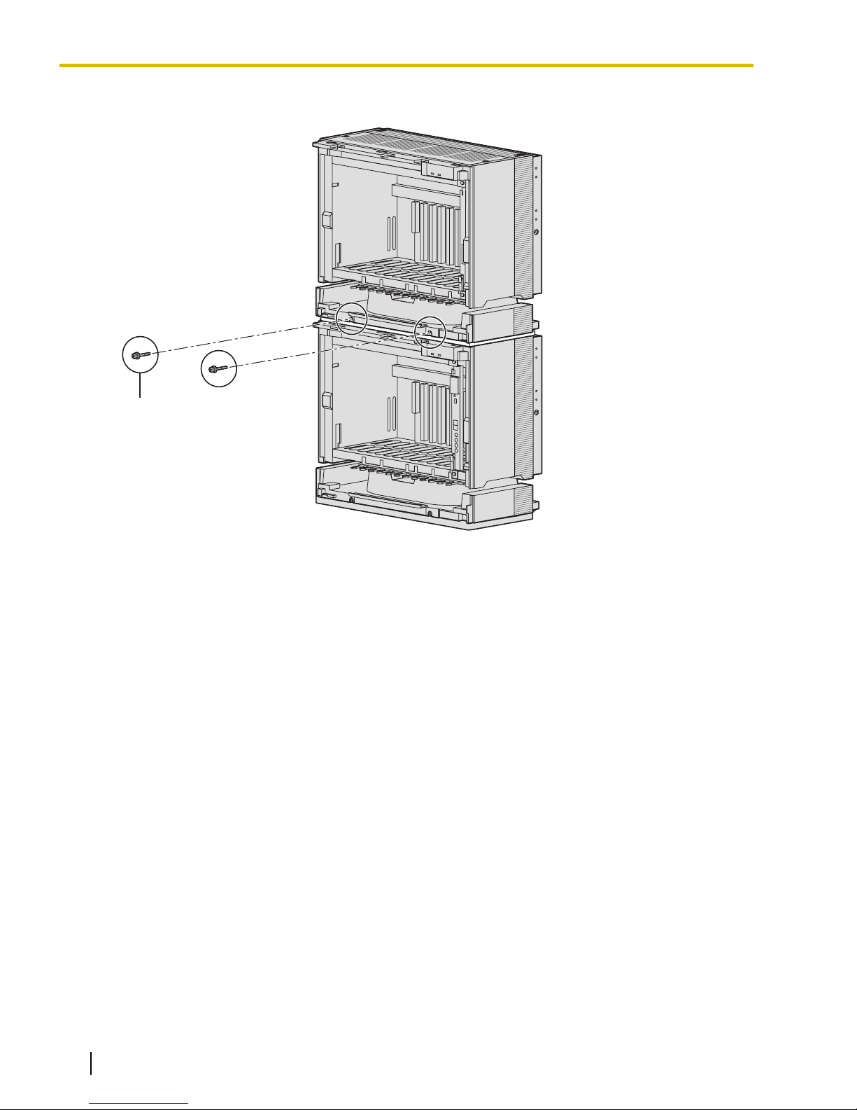
Screw (B)
3.2.5 Installation of Basic System or 2-shelf System (Floor Standing)
4. Secure Expansion Shelf 1 to the metal bracket with 2 screws (B).
Shelf installation is complete. Next, it is necessary to connect the shelves.
64 Installation Manual Document Version 2009-12
Page 65
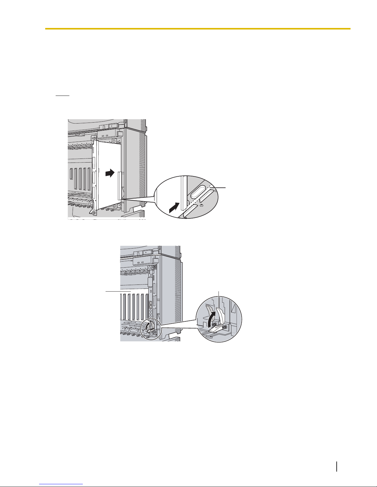
Guide Rail
Release Lever
Back Board
3.2.5 Installation of Basic System or 2-shelf System (Floor Standing)
Connecting Shelves
For the 2-shelf system, you need to install an optional BUS-M card in the Basic Shelf. To connect the shelves,
plug the Bus Cable (supplied with the BUS-M card) into the bottom slot of the BUS-M card. Then, plug the
other end into the BUS-S card built in to Expansion Shelf 1.
For details about the cards, refer to "3.5.1 BUS-M Card (KX-TDA6110)" and "3.6.1 BUS-S Card".
Note
When installing or removing the BUS-M card, make sure that the DC power supply is turned off.
1. Insert the BUS-M card along the guide rails in the BUS-M Card Slot (the right-most slot) of the Basic Shelf.
2. Push the release lever in the direction of the arrow so that the BUS-M card engages securely with the
connector on the back board.
Document Version 2009-12 Installation Manual 65
Page 66
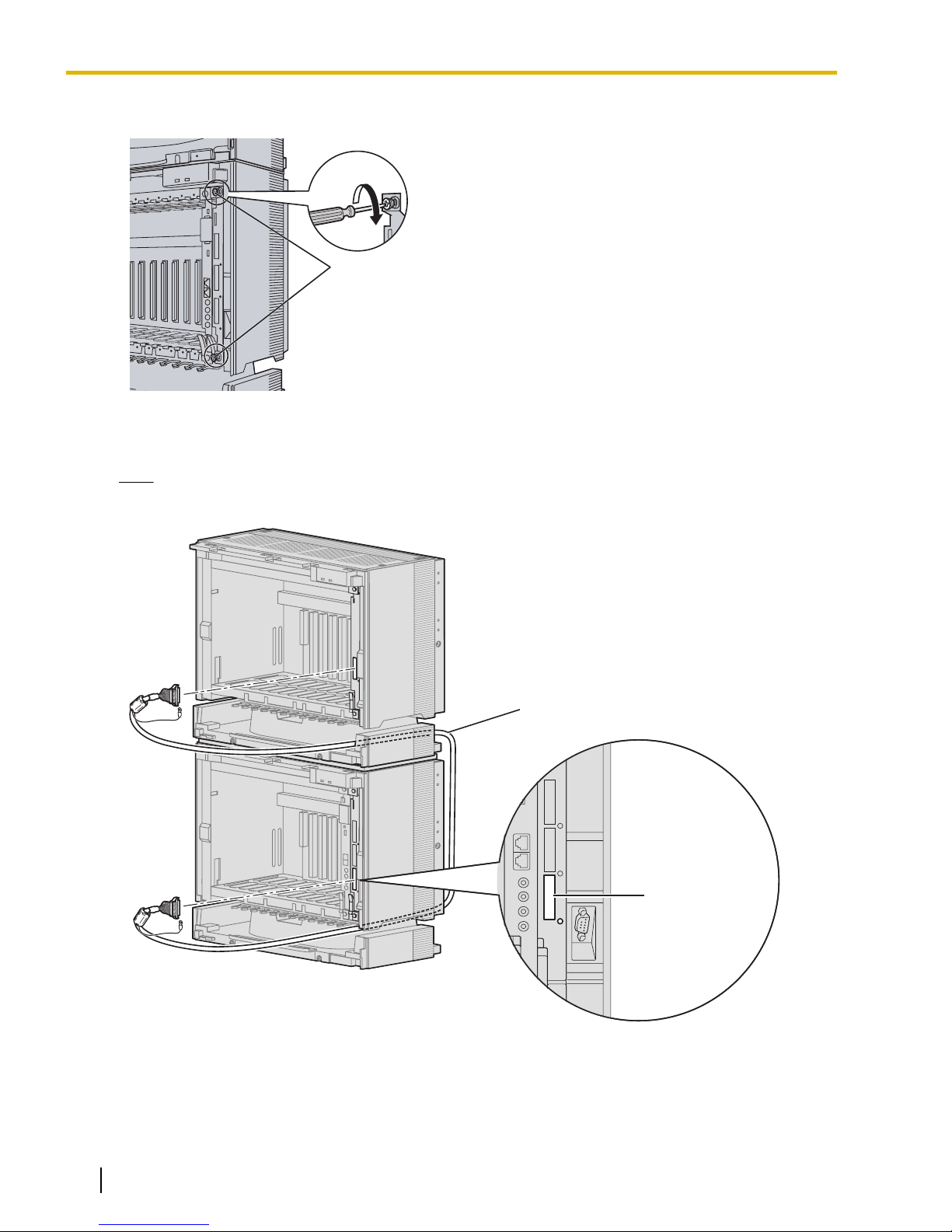
Screws
For Expansion
Shelf 1
Bus Cable
3.2.5 Installation of Basic System or 2-shelf System (Floor Standing)
3. Turn the 2 screws clockwise to fix the BUS-M card in place.
4. Plug the Bus Cable into the bottom port of the BUS-M card in the Basic Shelf. Then, plug the other end
into the BUS-S card in Expansion Shelf 1.
Note
When plugging or unplugging the Bus Cable, make sure that the DC power supply is turned off.
66 Installation Manual Document Version 2009-12
Page 67

Noise Shield Wire
Screw
3.2.5 Installation of Basic System or 2-shelf System (Floor Standing)
5. Attach the noise shield wires of the Bus Cable to the Basic Shelf and Expansion Shelf 1 with the screws
of the BUS-M card.
Note
When attaching or removing the noise shield wires, make sure that the DC power supply is turned off.
Document Version 2009-12 Installation Manual 67
Page 68

3-shelf
System
Expansion Shelf 1
Basic Shelf
Metal Bracket
Metal Bracket
Expansion Shelf 3
Expansion Shelf 2
Metal Bracket
Metal Bracket
Wall Bracket
(Right)
Wall Bracket
(Right)
Wall Bracket
(Left)
Wall Bracket
(Left)
4-shelf
System
Base Stand
Support Bracket
3.2.6 Installation of 3- or 4-shelf System (Tower Type)
3.2.6 Installation of 3- or 4-shelf System (Tower Type)
The PBX can be expanded to a 3- or 4-shelf system by mounting Expansion Shelves on the Basic Shelf. For
a 3- or 4-shelf system, you need a Mounting Kit, which supplies you with the base stands and wall brackets.
Construction of 3- or 4-shelf System (Tower Type)
68 Installation Manual Document Version 2009-12
Page 69
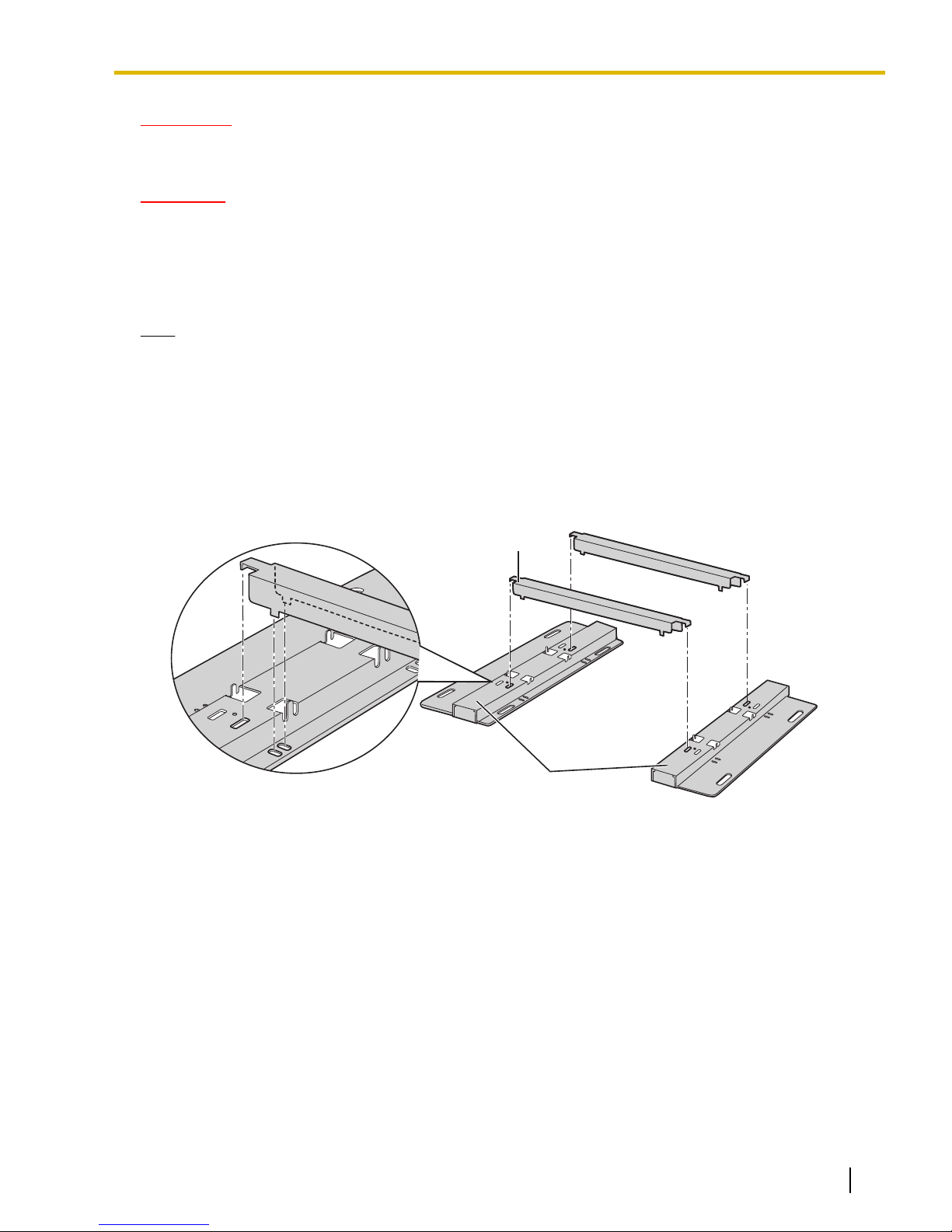
Support Bracket
Base Stand
3.2.6 Installation of 3- or 4-shelf System (Tower Type)
WARNING
Be careful not to drop any components. Dropping components may damage them or cause an
injury.
CAUTION
• Do not block the openings of the shelf. Allow space of at least 10 cm (4 in) at the sides of the shelf,
and 20 cm (8 in) above the top-mounted shelf.
• Make sure that the surface behind the shelf is flat and free of obstacles, so that the openings on the
back of the shelf will not be blocked.
• Make sure that the surface behind the shelf is not made of wood.
Note
• Make sure to remove the front cover from each shelf before installing the shelves (refer
to "3.2.3 Opening/Closing the Front Cover").
• Do not install any optional service cards or a PSU in the shelves before installation.
Installing the Basic Shelf
To install the Basic Shelf, attach the metal bracket (supplied with the Basic Shelf) to the base stands (supplied
with the Mounting Kit) first. Then, install the base stands on the floor and fix the Basic Shelf to them.
1. Attach the support brackets to the base stands.
Document Version 2009-12 Installation Manual 69
Page 70
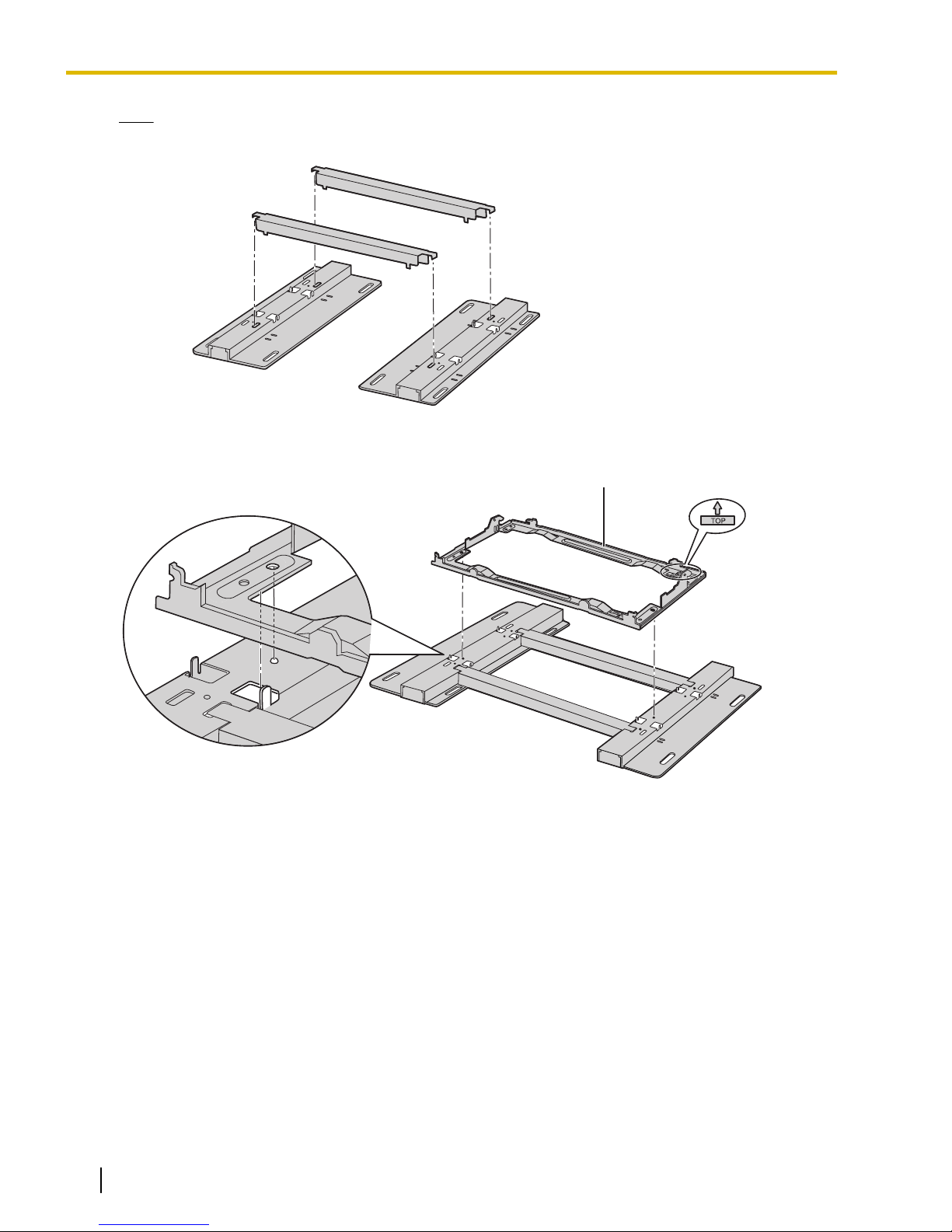
Metal Bracket
3.2.6 Installation of 3- or 4-shelf System (Tower Type)
Note
If necessary, it is possible to reverse the direction of the base stands as shown below:
2. Place the metal bracket on the base stands.
70 Installation Manual Document Version 2009-12
Page 71
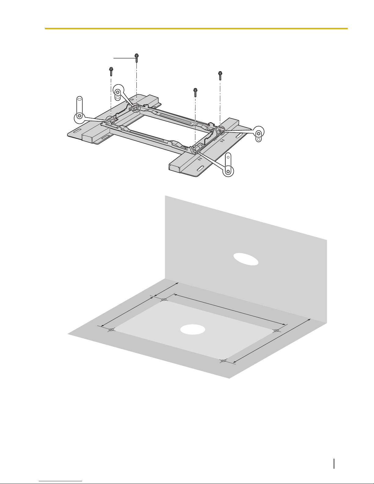
Screw (B)
510 mm
(20-1/16 in)*
Floor
Wall
287 mm
(11-5/16 in)
95 mm
(3-3/4 in)
382 mm
(15-1/16 in)
3.2.6 Installation of 3- or 4-shelf System (Tower Type)
3. Attach the metal bracket to the base stands with 4 screws (B).
4. Make 4 holes for anchor plugs on the floor, using the measurements indicated here.
* If the direction of the base stands is reversed, the measurement must be 443.4 mm (17-7/16 in).
Document Version 2009-12 Installation Manual 71
Page 72
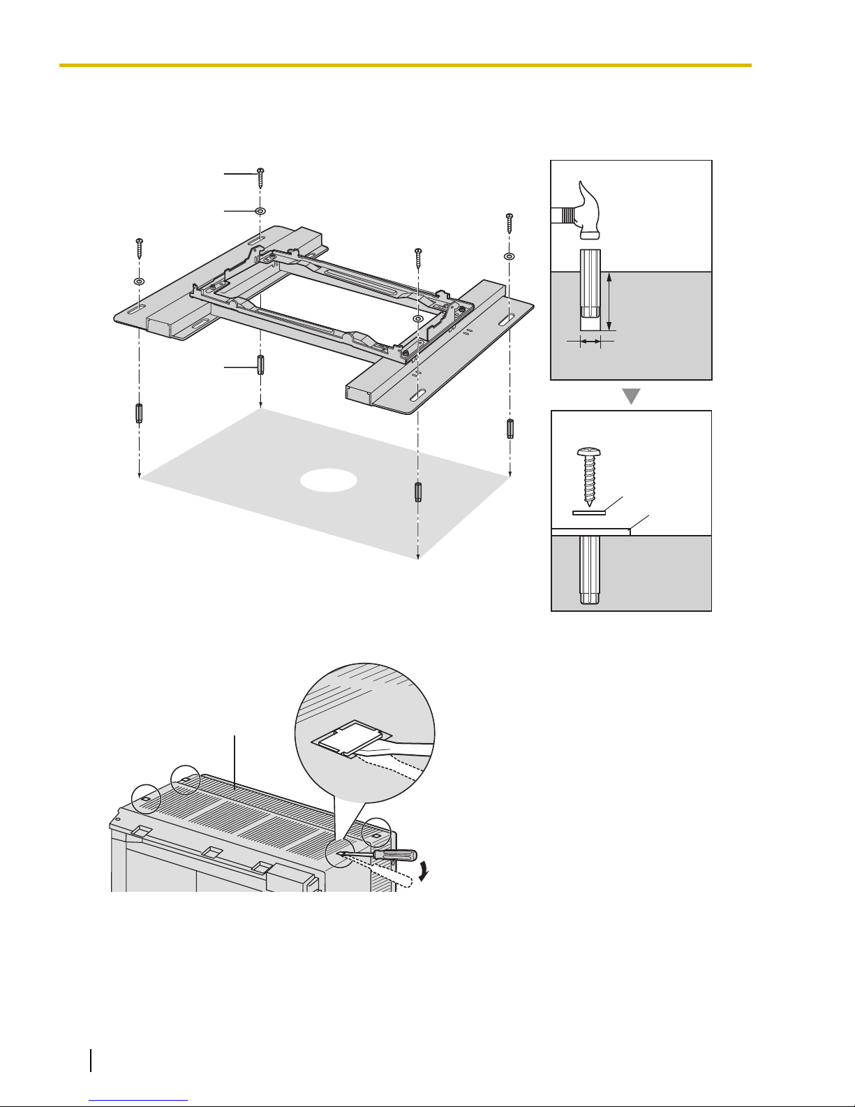
Anchor Plug
Hammer
30 mm
(1-3/16 in)
8 mm
(5/16 in)
Base
Stand
Washer
Screw (A)
Floor
Anchor
Plug
Screw (A)
Washer
Basic Shelf
3.2.6 Installation of 3- or 4-shelf System (Tower Type)
5. Install 4 anchor plugs in the holes on the floor.
Then, fasten the base stands to the floor loosely with 4 screws (A). (This makes it easy to adjust the position
of the shelves later.)
6. Remove the 4 tabs on the top cover of the Basic Shelf, by using a flathead screwdriver, as shown below.
72 Installation Manual Document Version 2009-12
Page 73
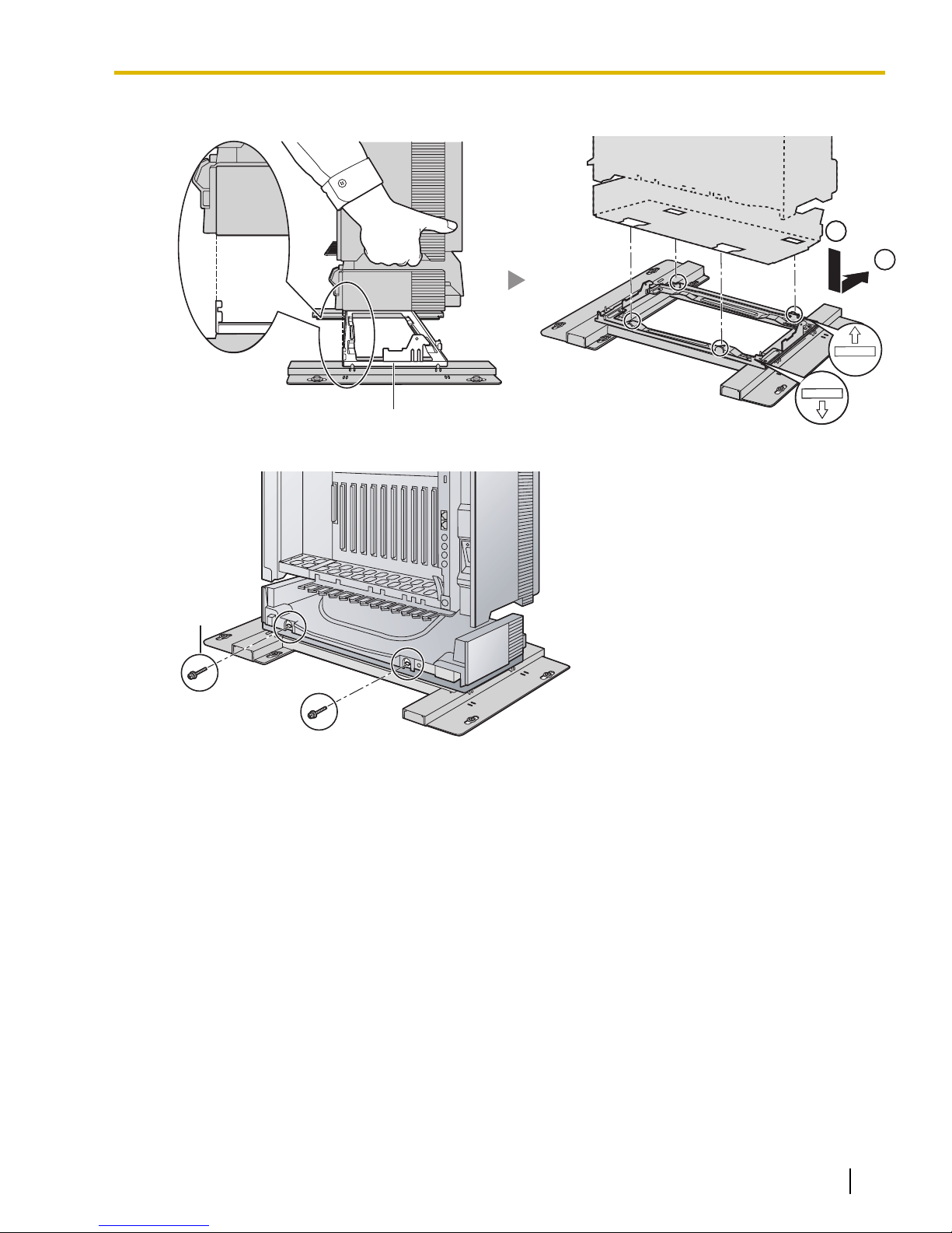
FRONT
1
2
FRONT
1
2
TOPTOP
Metal Bracket
Screw (B)
3.2.6 Installation of 3- or 4-shelf System (Tower Type)
7. Lift the Basic Shelf, attach it to the metal bracket, and slide it backwards until it locks.
8. Secure the Basic Shelf to the metal bracket with 2 screws (B).
Document Version 2009-12 Installation Manual 73
Page 74
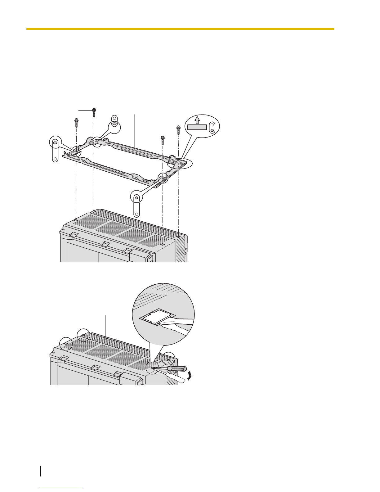
TOP
Screw (B)
Metal Bracket
Expansion Shelf 1
3.2.6 Installation of 3- or 4-shelf System (Tower Type)
Mounting Expansion Shelves 1 and 2
For the 3- or 4-shelf system, attach the metal bracket (supplied with the Expansion Shelf) to the Basic Shelf
first. After mounting Expansion Shelf 1 on the Basic Shelf, fix Expansion Shelf 1 to the wall. Then, mount
Expansion Shelf 2 on Expansion Shelf 1.
Expansion Shelf 1
1. Fix the metal bracket to the Basic Shelf with 4 screws (B).
2. Remove the 4 tabs on the top cover of Expansion Shelf 1, by using a flathead screwdriver, as shown below.
74 Installation Manual Document Version 2009-12
Page 75
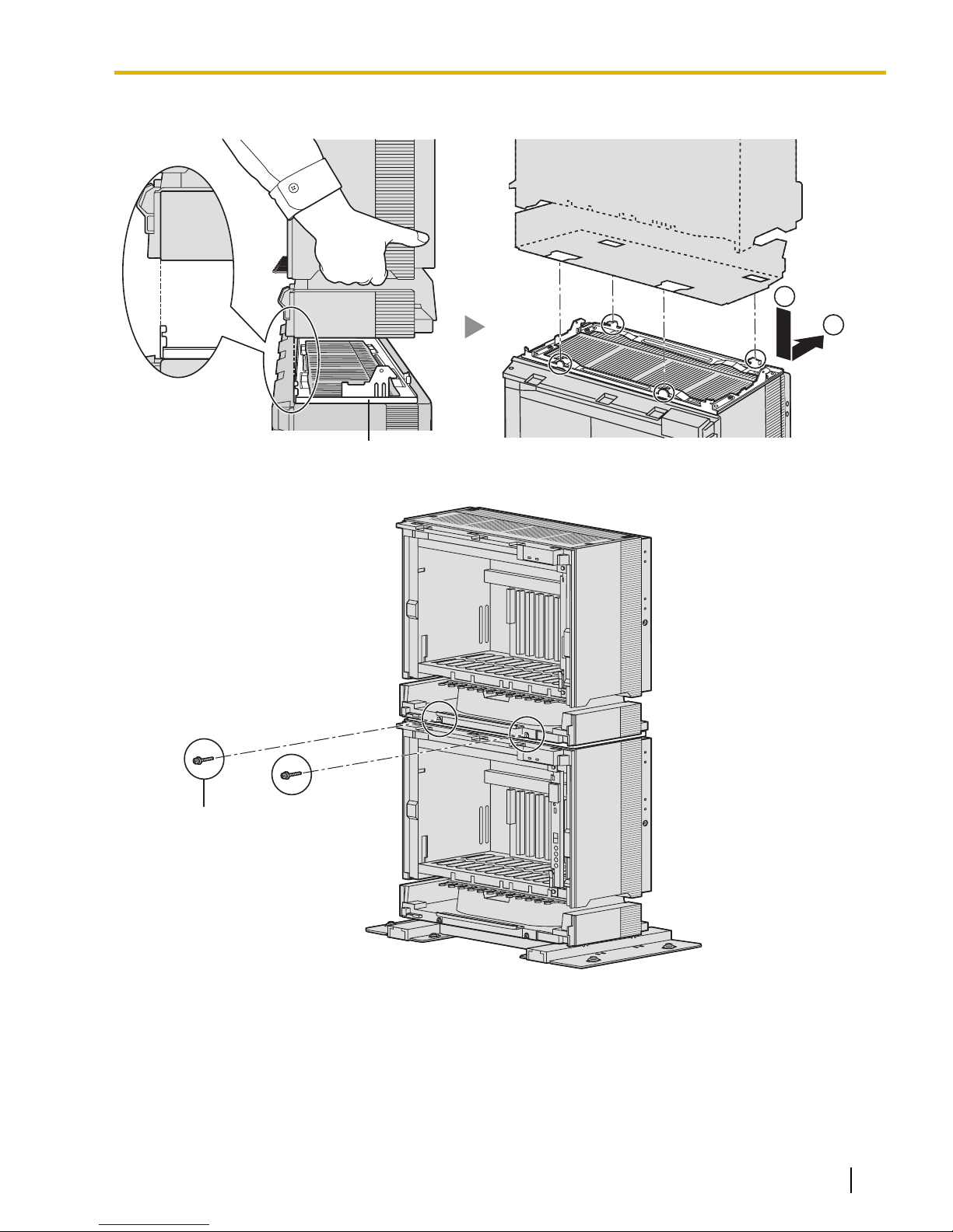
1
2
Metal Bracket
Screw (B)
3.2.6 Installation of 3- or 4-shelf System (Tower Type)
3. Lift Expansion Shelf 1, attach it to the metal bracket on the Basic Shelf, and slide it backwards until it locks.
4. Secure Expansion Shelf 1 to the metal bracket with 2 screws (B).
Document Version 2009-12 Installation Manual 75
Page 76
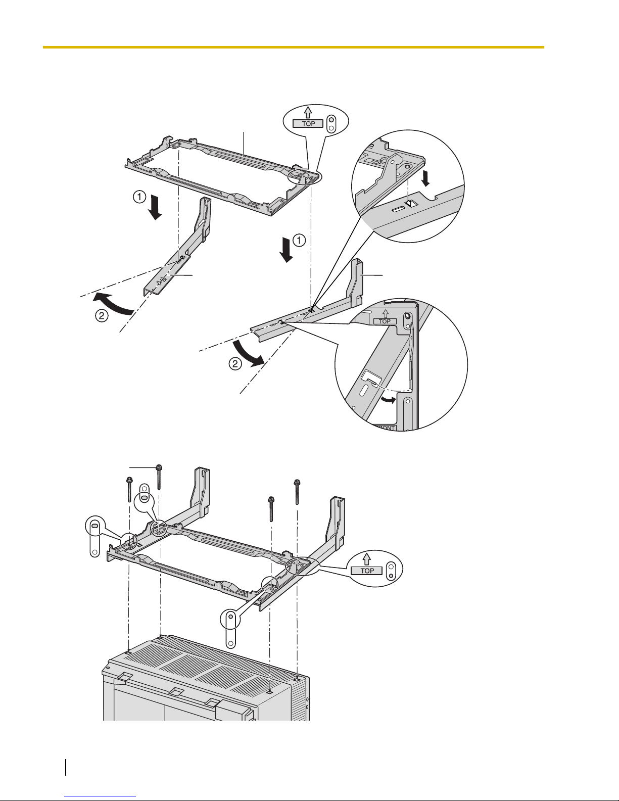
Wall Bracket (Left) Wall Bracket (Right)
Metal Bracket
Screw (D)
3.2.6 Installation of 3- or 4-shelf System (Tower Type)
Fixing to the Wall
1. Attach the metal bracket to the wall brackets.
2. Fix the metal bracket to Expansion Shelf 1 with 4 screws (D).
76 Installation Manual Document Version 2009-12
Page 77
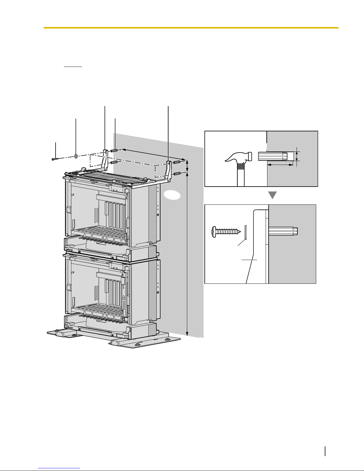
Screw (A)
Washer
Wall
Wall Bracket (Left) Wall Bracket (Right)
Anchor Plug
Hammer
Anchor Plug
Screw (A)
Washer
Wall Bracket
892 mm
(35-1/8 in)
62 mm
(2-7/16 in)
413 mm
(16-1/4 in)
30 mm
(1-3/16 in)
8 mm
(5/16 in)
3.2.6 Installation of 3- or 4-shelf System (Tower Type)
3. Install 4 anchor plugs in the wall, using the wall brackets as a template. Fix the wall brackets to the wall
with 4 screws (A).
Notice
• Drive mounting screws into the wall. Be careful to avoid touching any metal laths, wire laths or
metal plates in the wall.
• When installing anchor plugs in the wall, be careful not to damage or dirty the shelves.
Document Version 2009-12 Installation Manual 77
Page 78
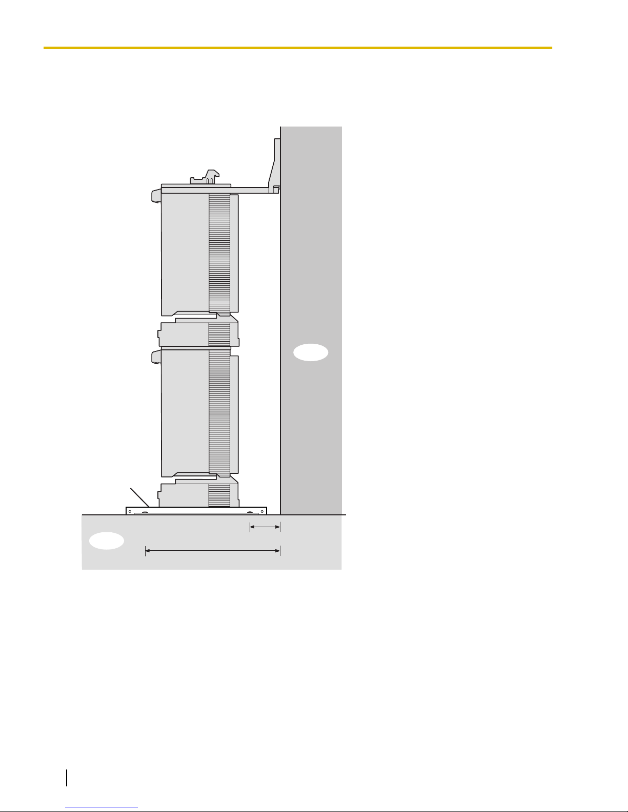
Floor
Wall
95 mm (3-3/4 in)
382 mm (15-1/16 in)
Base Stand
3.2.6 Installation of 3- or 4-shelf System (Tower Type)
4. Check that the shelves are standing exactly vertically. If the shelves are leaning slightly to one side, move
the base stands to adjust the position. (Since the base stands are attached loosely to the floor, it should
be possible to adjust the position of the shelves.)
Then, tighten the screws connecting the base stands to the floor.
78 Installation Manual Document Version 2009-12
Page 79

1
2
Metal Bracket
Screw (B)
3.2.6 Installation of 3- or 4-shelf System (Tower Type)
Expansion Shelf 2
1. Lift Expansion Shelf 2, attach it to the metal bracket fixed on Expansion Shelf 1, and slide it backwards
until it locks.
Secure Expansion Shelf to the metal bracket 2 with 2 screws (B).
2.
Installation of a 3-shelf system is complete. Next, it is necessary to connect the shelves.
If you are installing a 4-shelf system, follow the procedure below before connecting the shelves.
Document Version 2009-12 Installation Manual 79
Page 80
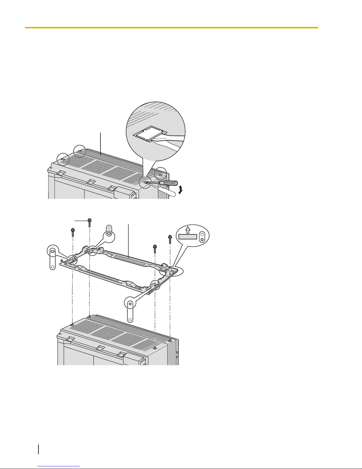
Expansion Shelf 2
TOP
Screw (B)
Metal Bracket
3.2.6 Installation of 3- or 4-shelf System (Tower Type)
Mounting Expansion Shelf 3
For the 4-shelf system, attach the metal bracket (supplied with Expansion Shelf 3) to Expansion Shelf 2 first.
Then, attach the wall brackets (supplied with the Mounting Kit) to Expansion Shelf 3. After mounting Expansion
Shelf 3 on Expansion Shelf 2, fix Expansion Shelf 3 to the wall.
Expansion Shelf 3
1. Remove the 4 tabs on the top cover of Expansion Shelf 2, by using a flathead screwdriver, as shown below.
2. Fix the metal bracket to Expansion Shelf 2 with 4 screws (B).
80 Installation Manual Document Version 2009-12
Page 81
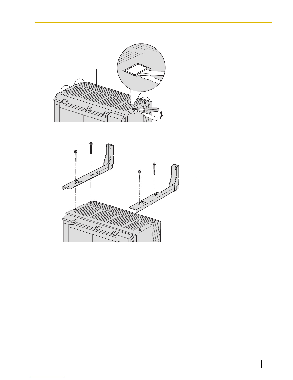
Expansion Shelf 3
Screw (D)
Wall Bracket (Right)
Wall Bracket (Left)
3.2.6 Installation of 3- or 4-shelf System (Tower Type)
3. Remove the 4 tabs on the top cover of Expansion Shelf 3, by using a flathead screwdriver, as shown below.
4. Fasten the wall brackets loosely to Expansion Shelf 3 with 4 screws (D). (This makes it easy to adjust the
position of the shelves later.)
Document Version 2009-12 Installation Manual 81
Page 82
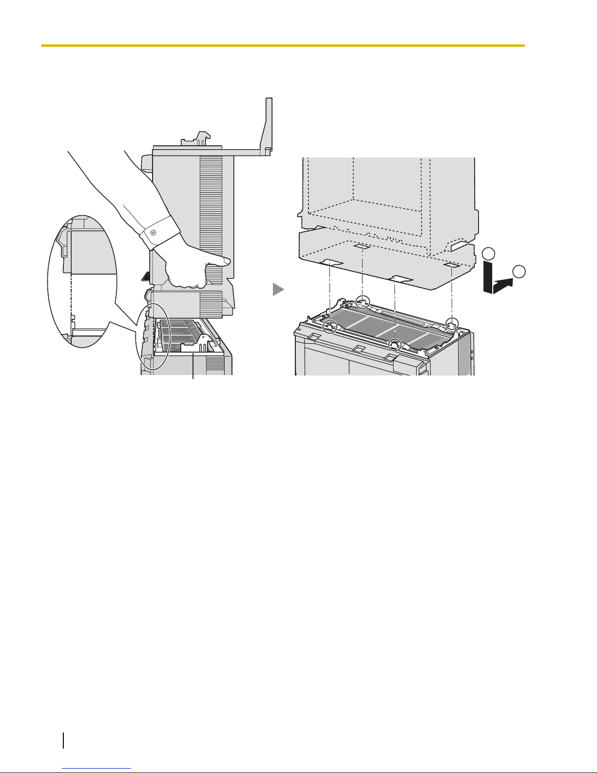
1
2
Metal Bracket
3.2.6 Installation of 3- or 4-shelf System (Tower Type)
5. Lift Expansion Shelf 3, attach it to the metal bracket fixed on Expansion Shelf 2, and slide it backwards
until it locks.
82 Installation Manual Document Version 2009-12
Page 83
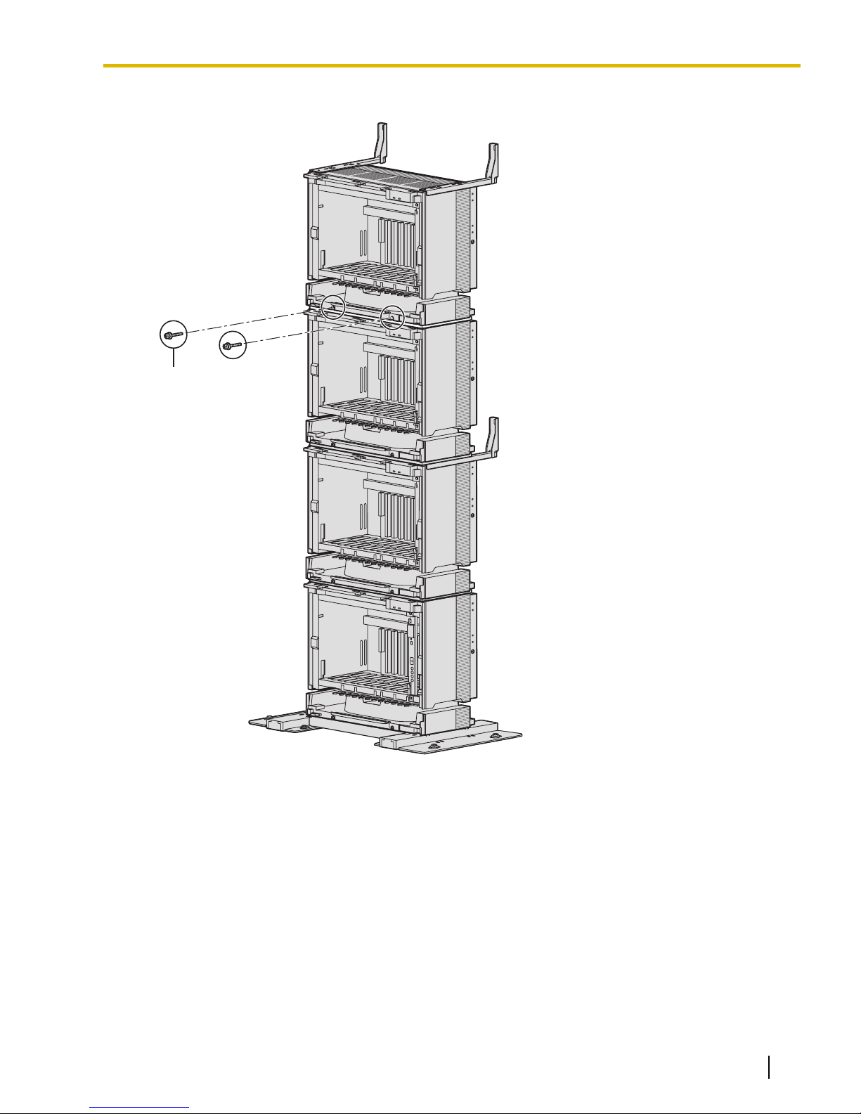
Screw (B)
3.2.6 Installation of 3- or 4-shelf System (Tower Type)
6. Secure Expansion Shelf 3 to the metal bracket with 2 screws (B).
Document Version 2009-12 Installation Manual 83
Page 84
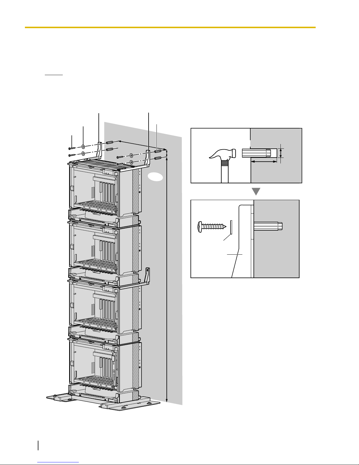
62 mm
(2-7/16 in)
1731 mm
(68-1/8 in)
8 mm
(5/16 in)
30 mm
(1-3/16 in)
Anchor Plug
Wall
Screw (A)
Washer
Wall Bracket (Left)
Wall Bracket (Right)
Screw (A)
Hammer
Anchor Plug
Washer
Wall Bracket
413 mm
(16-1/4 in)
3.2.6 Installation of 3- or 4-shelf System (Tower Type)
Fixing to the Wall
1. Install 4 anchor plugs in the wall, using the wall brackets as a template. Fix the wall brackets to the wall
with 4 screws (A).
Notice
• Drive mounting screws into the wall. Be careful to avoid touching any metal laths, wire laths or
metal plates in the wall.
• When installing anchor plugs in the wall, be careful not to damage or dirty the shelves.
84 Installation Manual Document Version 2009-12
Page 85
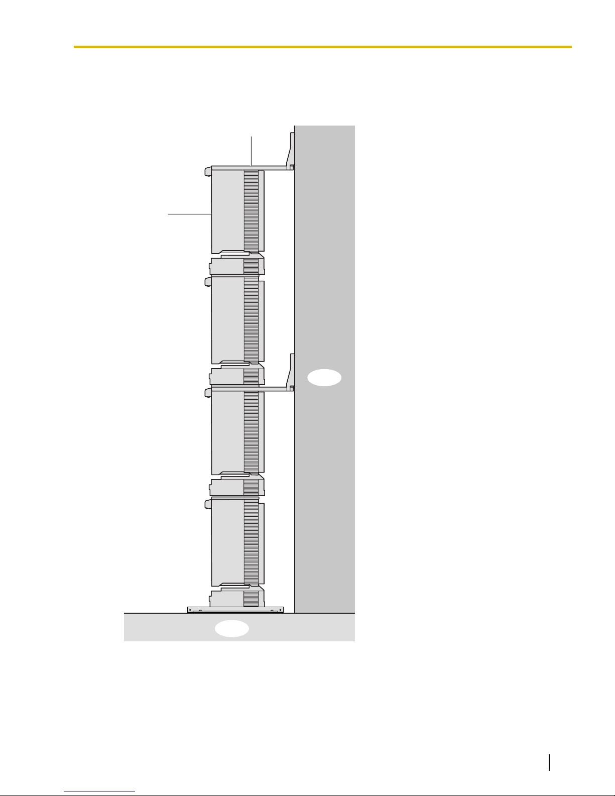
Floor
Wall
Expansion
Shelf 3
Wall Bracket
3.2.6 Installation of 3- or 4-shelf System (Tower Type)
2. Check that the shelves are standing exactly vertically. If the upper shelves are leaning slightly to one side,
move Expansion Shelf 3 to adjust the position. (Since the wall brackets are attached loosely to Expansion
Shelf 3, it should be possible to adjust the position of the shelves.)
Then, tighten the screws connecting the wall brackets to Expansion Shelf 3.
Shelf installation is complete. Next, it is necessary to connect the shelves.
Document Version 2009-12 Installation Manual 85
Page 86

inside
BUS-M Card
Screw
BUS-ME Card
(for Expansion Shelf 3)
BUS-ME Card
(for Expansion Shelf 2)
Guide Rail
3.2.6 Installation of 3- or 4-shelf System (Tower Type)
Connecting Shelves
For a 3- or 4-shelf system, you need to install an optional BUS-M card and BUS-ME card(s) in the Basic Shelf.
To connect the shelves, plug the Bus Cables (supplied with the BUS-M card or BUS-ME card) into the slots
of the BUS-M card. Then, plug the other end of each Bus Cable into the BUS-S card built in to each Expansion
Shelf.
For details about the cards, refer to "3.5.1 BUS-M Card (KX-TDA6110)", "3.5.2 BUS-ME Card
(KX-TDA6111)", and "3.6.1 BUS-S Card".
Note
When installing or removing the BUS-M card, make sure that the DC power supply is turned off.
1. Mount 1 BUS-ME card (for a 3-shelf system), or 2 BUS-ME cards (for a 4-shelf system) on the BUS-M card
as shown below.
2. Insert the BUS-M card along the guide rails in the BUS-M Card Slot (the right-most slot) of the Basic Shelf.
86 Installation Manual Document Version 2009-12
Page 87
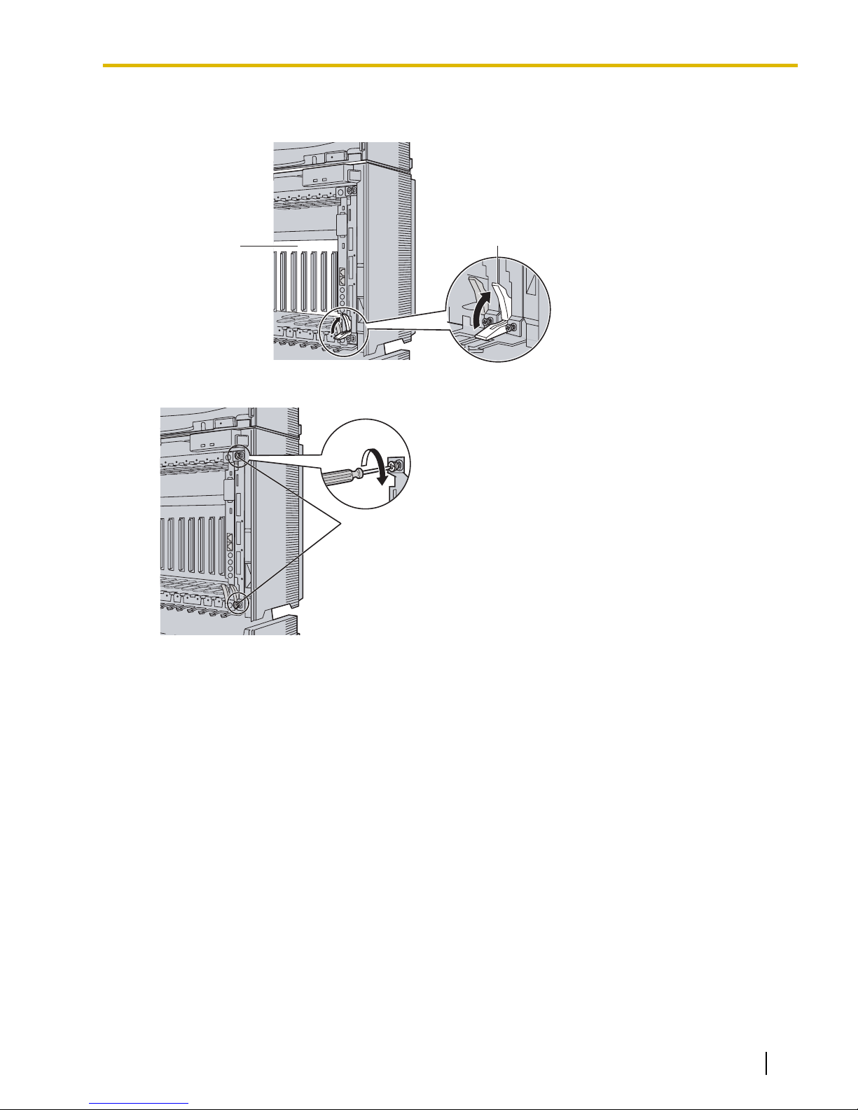
Release Lever
Back Board
Screws
3.2.6 Installation of 3- or 4-shelf System (Tower Type)
3. Push the release lever in the direction of the arrow so that the BUS-M card engages securely with the
connector on the back board.
4. Turn the 2 screws clockwise to fix the BUS-M card in place.
Document Version 2009-12 Installation Manual 87
Page 88

Bus Cable
For Expansion
Shelf 3
For Expansion
Shelf 2
For Expansion
Shelf 1
3.2.6 Installation of 3- or 4-shelf System (Tower Type)
5. Plug each Bus Cable into the corresponding port of the BUS-M card in the Basic Shelf. Then, plug the
other end into the BUS-S card in each Expansion Shelf.
Note
When plugging or unplugging the Bus Cables, make sure that the DC power supply is turned off.
88 Installation Manual Document Version 2009-12
Page 89
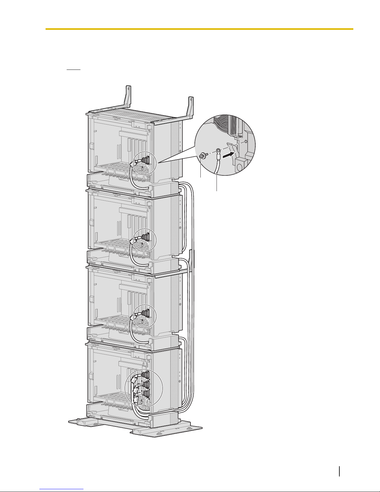
Noise Shield Wire
Screw
3.2.6 Installation of 3- or 4-shelf System (Tower Type)
6. Attach the noise shield wires of each Bus Cable to the Basic Shelf and each Expansion Shelf with the
screws of the BUS-M card.
Note
When attaching or removing the noise shield wires, make sure that the DC power supply is turned off.
Document Version 2009-12 Installation Manual 89
Page 90
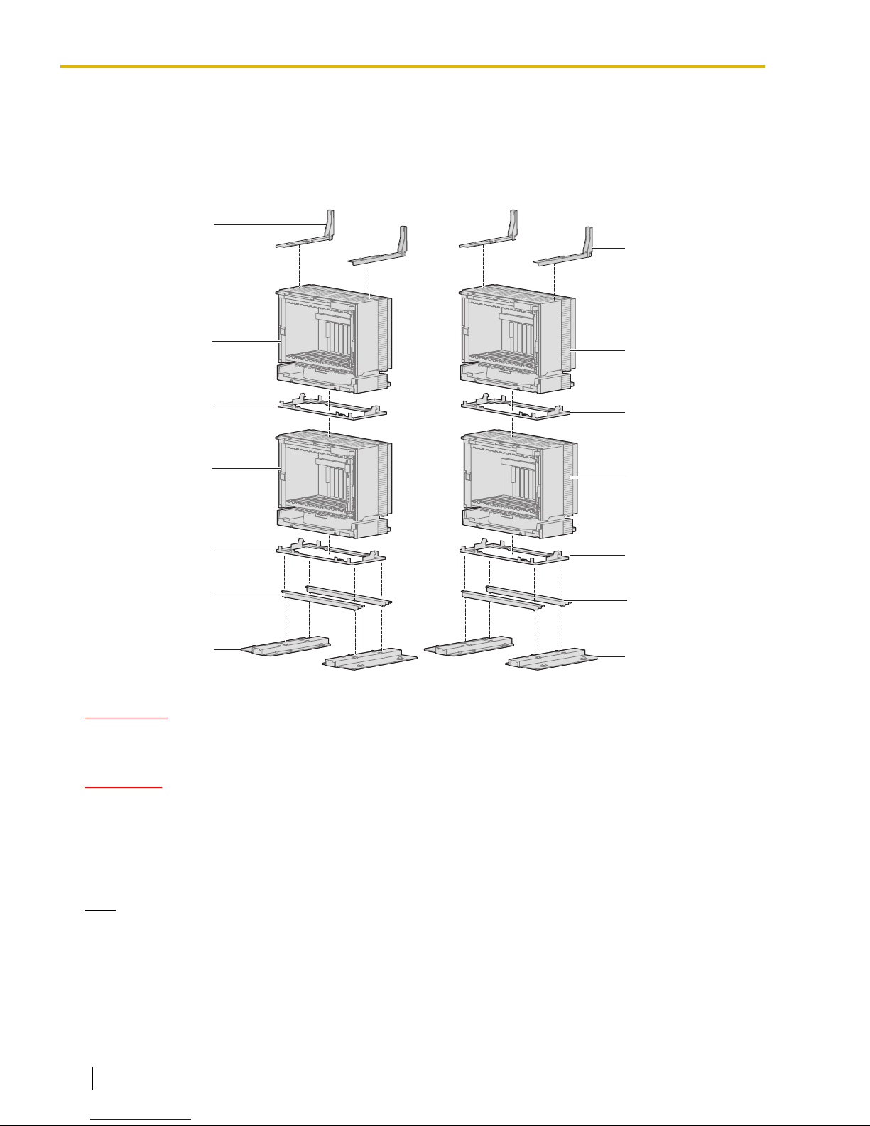
Expansion Shelf 3
Expansion Shelf 2
Metal Bracket
Metal Bracket
Support Bracket
Base Stand
Expansion Shelf 1
Wall Bracket
(Right)
Wall Bracket
(Left)
Basic Shelf
Metal Bracket
Metal Bracket
Base Stand
Support Bracket
3.2.7 Installation of 4-shelf System (Side-by-side Type)
3.2.7 Installation of 4-shelf System (Side-by-side Type)
When vertical space is limited, it is possible to install shelves side-by-side. Installing the system using base
stands (supplied with an optional Mounting Kit) makes it easy to reinstall shelves in a different place.
Construction of 4-shelf System (Side-by-side Type)
WARNING
Be careful not to drop any components. Dropping components may damage them or cause an
injury.
CAUTION
• Do not block the openings of the shelf. Allow space of at least 10 cm (4 in) at the sides of the shelf,
and 20 cm (8 in) above the top-mounted shelf.
• Make sure that the surface behind the shelf is flat and free of obstacles, so that the openings on the
back of the shelf will not be blocked.
• Make sure that the surface behind the shelf is not made of wood.
Note
• Make sure to remove the front cover from each shelf before installing the shelves (refer
to "3.2.3 Opening/Closing the Front Cover").
• Do not install any optional service cards or a PSU in the shelves before installation.
• Make sure to install the shelves where the Bus Cable (supplied with a BUS-M card or BUS-ME card)
can reach the shelves.
90 Installation Manual Document Version 2009-12
Page 91
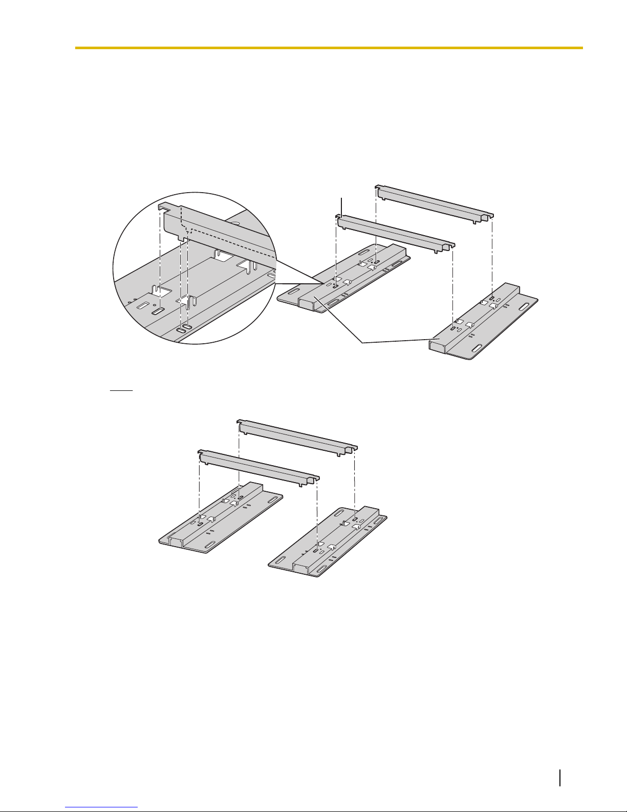
Support Bracket
Base Stand
3.2.7 Installation of 4-shelf System (Side-by-side Type)
Installing the Basic Shelf and Expansion Shelf 1
To install the Basic Shelf, attach the metal bracket (supplied with the Basic Shelf) to the base stands (supplied
with the optional Mounting Kit) first. Then, install the base stands on the floor and fix the Basic Shelf to it. To
install Expansion Shelf 1, attach the metal bracket (supplied with Expansion Shelf 1) to the Basic Shelf. Then,
mount Expansion Shelf 1 on the Basic Shelf.
Basic Shelf
1. Attach the support brackets to the base stands.
Note
If necessary, it is possible to reverse the direction of the base stands as shown below:
Document Version 2009-12 Installation Manual 91
Page 92
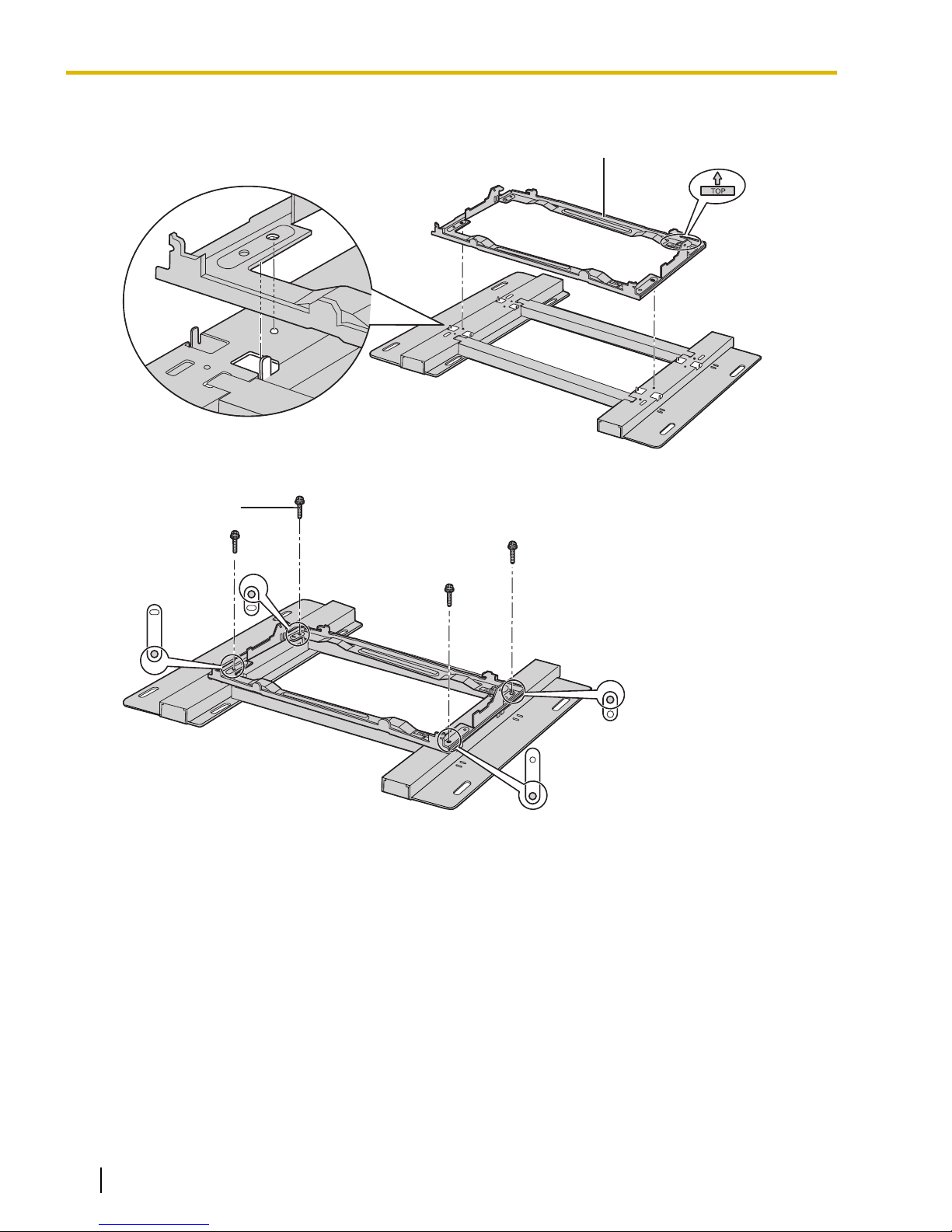
Metal Bracket
Screw (B)
3.2.7 Installation of 4-shelf System (Side-by-side Type)
2. Place the metal bracket on the base stands.
3. Attach the metal bracket to the base stands with 4 screws (B).
92 Installation Manual Document Version 2009-12
Page 93
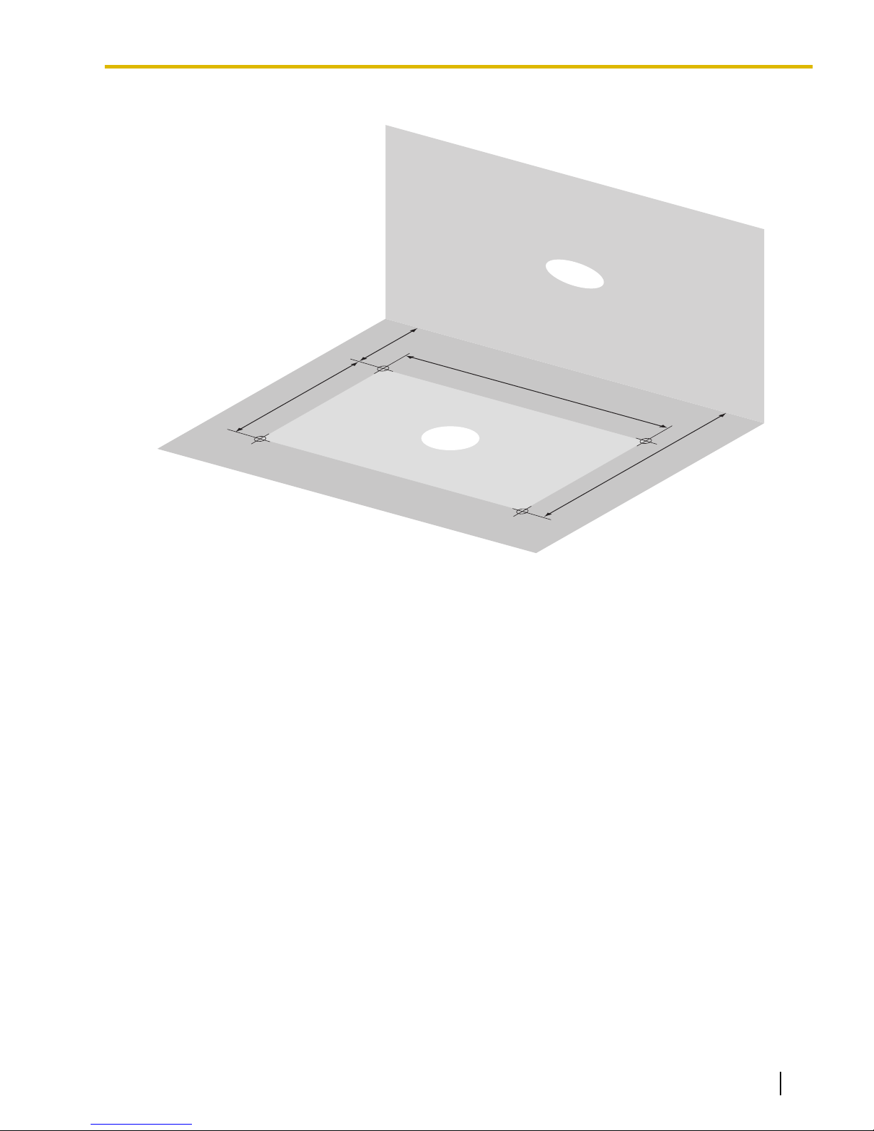
510 mm
(20-1/16 in)*
Floor
Wall
287 mm
(11-5/16 in)
95 mm
(3-3/4 in)
382 mm
(15-1/16 in)
3.2.7 Installation of 4-shelf System (Side-by-side Type)
4. Make 4 holes for anchor plugs on the floor, using the measurements indicated here.
* If the direction of the base stands is reversed, the measurement must be 443.4 mm (17-7/16 in).
Document Version 2009-12 Installation Manual 93
Page 94
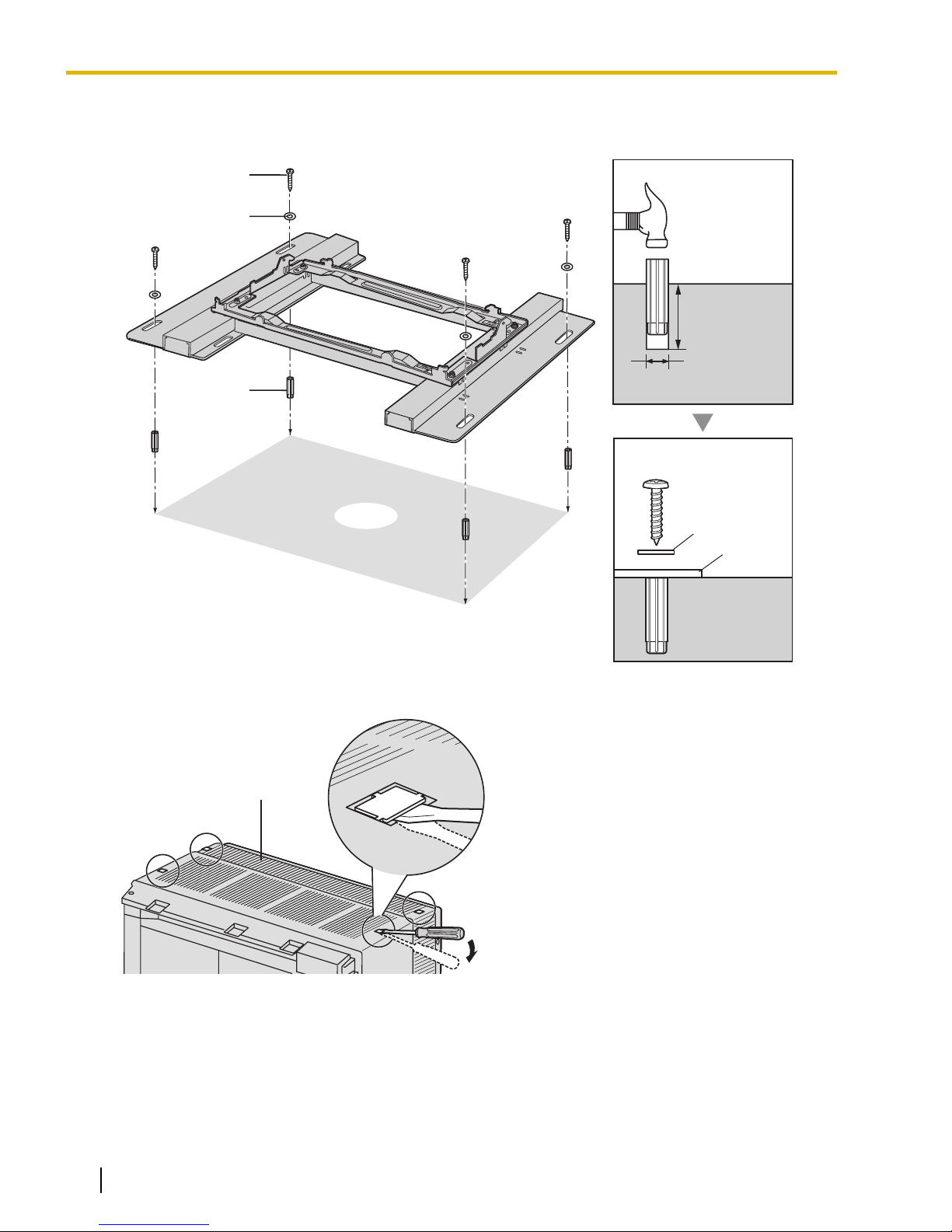
Anchor Plug
Hammer
30 mm
(1-3/16 in)
8 mm
(5/16 in)
Base
Stand
Washer
Screw (A)
Floor
Anchor
Plug
Screw (A)
Washer
Basic Shelf
3.2.7 Installation of 4-shelf System (Side-by-side Type)
5. Install 4 anchor plugs in the holes on the floor.
Then, fasten the base stands to the floor with 4 screws (A).
6. Remove the 4 tabs on the top cover of the Basic Shelf, by using a flathead screwdriver, as shown below.
94 Installation Manual Document Version 2009-12
Page 95
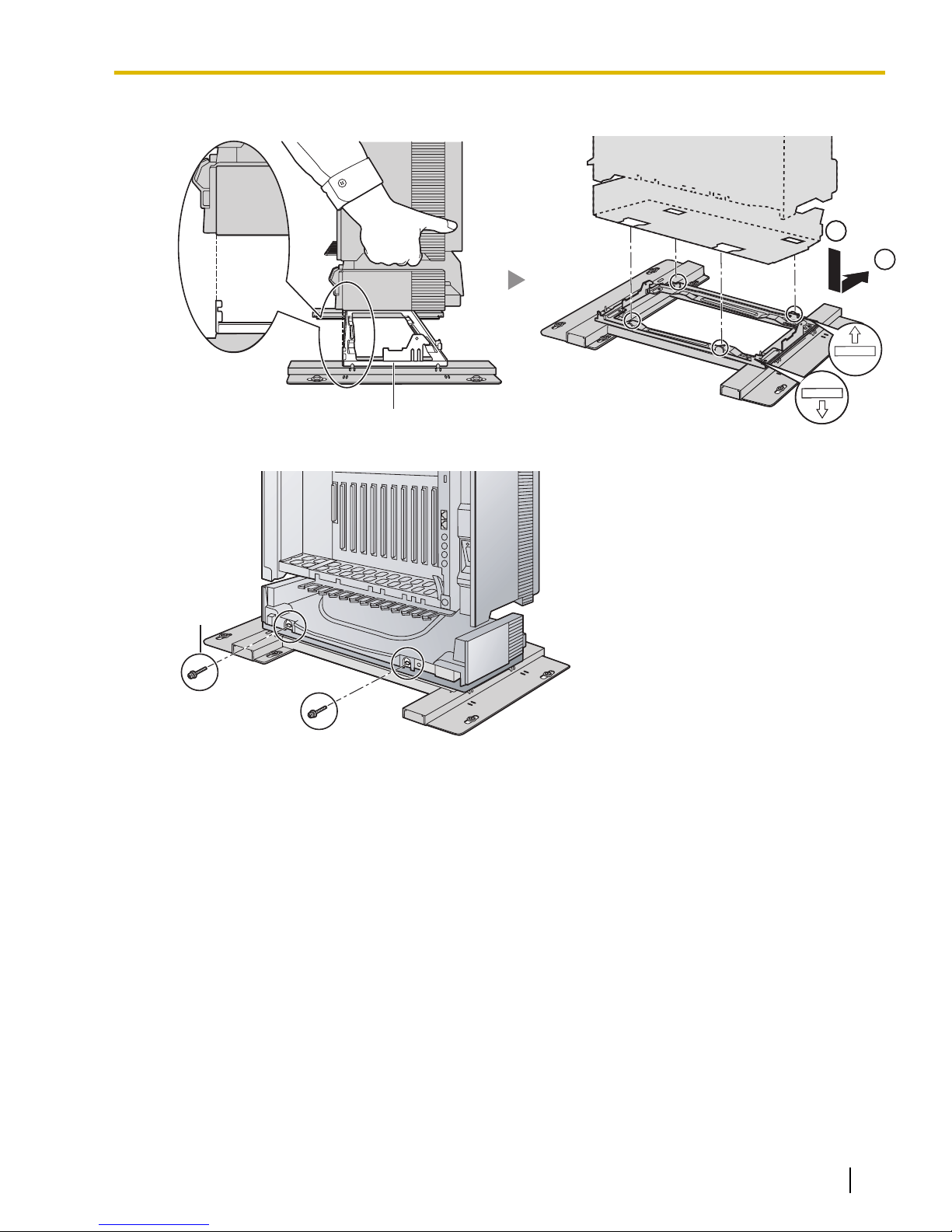
FRONT
1
2
FRONT
1
2
TOPTOP
Metal Bracket
Screw (B)
3.2.7 Installation of 4-shelf System (Side-by-side Type)
7. Lift the Basic Shelf, attach it to the metal bracket, and slide it backwards until it locks.
8. Secure the Basic Shelf to the metal bracket with 2 screws (B).
Document Version 2009-12 Installation Manual 95
Page 96
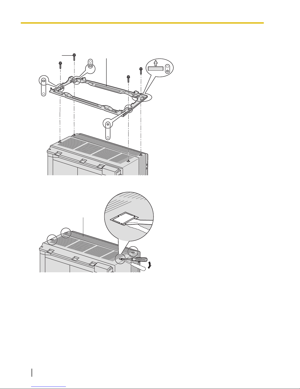
TOP
Screw (B)
Metal Bracket
Expansion Shelf 1
3.2.7 Installation of 4-shelf System (Side-by-side Type)
Expansion Shelf 1
1. Fix the metal bracket to the Basic Shelf with 4 screws (B).
2. Remove the 4 tabs on the top cover of Expansion Shelf 1, by using a flathead screwdriver, as shown below.
96 Installation Manual Document Version 2009-12
Page 97
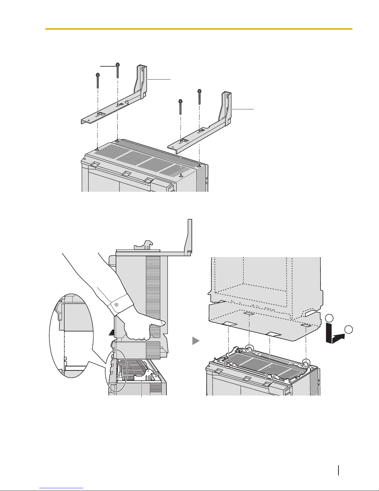
Screw (D)
Wall Bracket (Right)
Wall Bracket (Left)
1
2
Metal Bracket
3.2.7 Installation of 4-shelf System (Side-by-side Type)
3. Fasten the wall brackets loosely to Expansion Shelf 1 with 4 screws (D). (This makes it easy to adjust the
position of the shelves later.)
4. Lift Expansion Shelf 1, attach it to the metal bracket fixed on the Basic Shelf, and slide it backwards until
it locks.
Document Version 2009-12 Installation Manual 97
Page 98
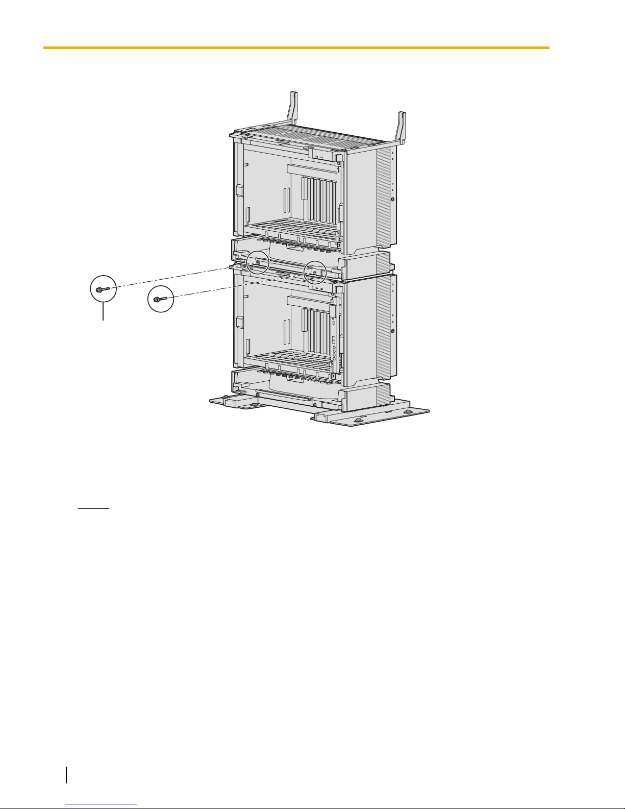
Screw (B)
3.2.7 Installation of 4-shelf System (Side-by-side Type)
5. Secure Expansion Shelf 1 to the metal bracket with 2 screws (B).
Fixing to the Wall
1. Install 4 anchor plugs in the wall, using the wall brackets as a template. Fix the wall brackets to the wall
with 4 screws (A).
Notice
• Drive mounting screws into the wall. Be careful to avoid touching any metal laths, wire laths or
metal plates in the wall.
98 Installation Manual Document Version 2009-12
Page 99
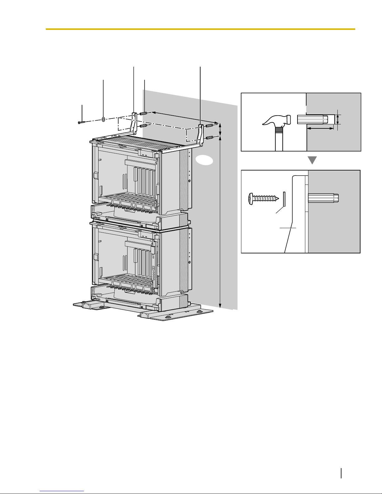
Screw (A)
Washer
Wall
Wall Bracket (Left) Wall Bracket (Right)
Anchor Plug
Hammer
Anchor Plug
30 mm
(1-3/16 in)
413 mm
(16-1/4 in)
8 mm
(5/16 in)
892 mm
(35-1/8 in)
62 mm
(2-7/16 in)
Screw (A)
Washer
Wall Bracket
3.2.7 Installation of 4-shelf System (Side-by-side Type)
• When installing anchor plugs in the wall, be careful not to damage or dirty the shelves.
Document Version 2009-12 Installation Manual 99
Page 100
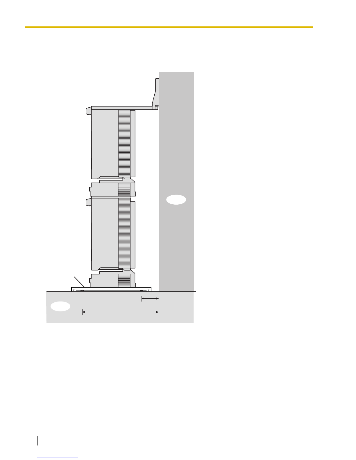
Floor
Wall
95 mm (3-3/4 in)
382 mm (15-1/16 in)
Base Stand
3.2.7 Installation of 4-shelf System (Side-by-side Type)
2. Check that the shelves are standing exactly vertically. If the shelves are leaning slightly to one side, move
the base stands to adjust the position. (Since the base stands are attached loosely to the floor, it should
be possible to adjust the position of the shelves.)
Then, tighten the screws connecting the base stands to the floor.
Installation of the first 2 shelves is complete. Next, install Expansion Shelves 2 and 3 next to the Basic Shelf
and Expansion Shelf 1.
100 Installation Manual Document Version 2009-12
 Loading...