

Page 1
KX-TD816
KX-TD1232
Digital Super Hybrid System
Installation Manual
D1232
DIGITAL SUPER HYBRID SYSTEM
Panasonic
Panasonic
D816
DIGITAL SUPER HYBRID SYSTEM
Thank you for purchasing this Panasonic Model KX-TD816/KX-TD1232, Digital Super Hybrid System.
Please read this manual before connecting the Digital Super Hybrid System.
This manual is for software version P341I, P342I or later for KX-TD816 and P241I, P242I or later for
KX-TD1232.
www.voicesonic.com
Phone 1 877-289-2829
Panasonic Telephone Systems
Panasonic KX-TD1232, KXTD1232, KX TD1232, TD1232, KX-TD816, KXTD816, KX TD816, TD816
Panasonic KX-TD816 / KX-TD1232
Page 2
2 System Components
System Components
System Components Table
Model Description
Service Unit KX-TD816
KX-TD1232
Digital Super Hybrid Sy stem (Main Un it)
Digital Super Hybrid Sy stem (Main Un it)
Telephone KX-T7520
KX-T7531
KX-T7533
KX-T7536
KX-T7550
KX-T7425
KX-T7433
KX-T7436
KX-T7450
KX-T7220
KX-T7230
KX-T7235
KX-T7250
KX-T7320
KX-T7330
KX-T7350
KX-T7130
KX-T7020
KX-T7030
KX-T7033
KX-T7050
KX-T7055
KX-TD7500
Digital proprietary telephone
Digital proprietary telephone with 1-line display
Digital proprietary telephone with 3-line display
Digital proprietary telephone with 6-line display
Digital proprietary telephone
Digital proprietary telephone
Digital proprietary telephone with 3-line display
Digital proprietary telephone with 6-line display
Digital proprietary telephone
Digital proprietary telephone
Digital proprietary telephone with 2-line display
Digital proprietary telephone with 6-line display
Digital proprietary telephone
Proprietary telephone
Proprietary telephone with 1-line d isplay
Proprietary telephone
Proprietary telephone with 1-line d isplay
Proprietary telephone
Proprietary telephone with 1-line d isplay
Proprietary telephone with 1-line d isplay
Proprietary telephone
Proprietary telephone
DECT portable station
Page 3

System Components 3
*1Can be installed in the KX-TD816 only.
*
2
Can be installed in the KX-TD1232 only.
Note
• In this manual, the suffix of each model number are omitted.
Optional
Equipment
KX-T7540
KX-T7541
KX-T7545
KX-T7440
KX-T7441
KX-T7240
KX-T7040
KX-T7340
Digital DSS Console
Digital Attendant Console
Add-on Key Module
Digital DSS Console
DSS Console for Attendant
Digital DSS Console
DSS Console
DSS Console
KX-TD142
KX-TD144
KX-TD146
KX-TD160
KX-TD170
KX-TD174
KX-TD180
KX-TD184
KX-TD189
KX-TD190*
1
KX-TD191*
2
KX-TD192*
2
KX-TD194
KX-TD196*
2
KX-TD197
KX-TD198*
1
KX-TD199*
1
KX-TD280
KX-TD286
KX-TD290
Cell Station
Cell Station Interface Unit
Cell Station Interface Unit
Doorphone Card
8-Station Line Unit
16 SLT Line Circuit Unit
4-CO Line Unit
E&M (TIE) Lin e Unit
Pay Tone Card
DISA Unit
DISA Card
System Inter Connection Card (two cards with Connection Cable)
SLT Message Waiting Lamp Adaptor Unit
Remote Card
High Speed Remote Card
Remote Unit
DISA Card
2-ISDN S0 Line Unit
6-ISDN S0 Line Unit
Primary Rate Interface ISDN Ex pansion Unit
KX-T30865
KX-A46
KX-A277
Doorphone
Battery Adaptor
AC Adaptor
System Components Table
Model Description
Page 4

4 Important Information
Important Information
When using your telephone equipment, basi c safety prec autions shou ld alwa ys be follo wed to
reduce the ris k of fire, electric shock and injury to persons, including the following:
a) Read and understand all instructions.
b) Follow all warnings and instructions marked on the product.
c) Unplug this product from the wall outlet before cleaning. Do not use liquid cleaners or
aerosol cleaners. Use a damp cloth for cleaning.
d) Do not use t his product near water , for e xample, near a bathtub, w ash bowl, kitch en sink,
or laundry tub, in a wet basement, or near a swimming pool.
e) Do not place this product on an unstable cart, stand, or table. The product may fall,
causing serious damage to the product.
f) Slots and openings in the cabi net and t he back or bottom are prov ided for vent ilation , to
protect it from overheating, these openings must not be blocked or covered. The
openings should never be block ed by placing the product on the bed, sofa, r ug, or other
similar surface. This product should never be placed near or over a radiator or heat
register. This product should not be placed in a built-in installation unless proper
ventilation is provi ded.
g) This product should be operated only from the type of power source indicated on the
marking label. If you are not sure of th e type of power suppl y to your home, consult your
dealer or local power company.
h) This product is equipped with a three wire grounding type plug, a plug having a third
(grounding) pin. This plug will only fit into a grounding type power outlet. This is a
safety feature. If you are unable to insert t he plug into the outle t, contact your elect rician
to replace your obsolete outlet. Do not defeat the safety purpose of the grounding type
plug.
i) Do not allow anything to rest on the power cord. Do not locate this product where the
cord will be abused by people walking on it.
j) Do not overload wall outlets and extension cords as this can result in the risk of fire or
electric shock.
k) Ne ver push objects of any ki nd into this product throu gh cabinet sl ots as the y may touch
dangerous voltage points or short out parts that could result in a risk of fire or electric
shock. Never spill liquid of any kind on the product.
l) To reduce the risk of electric shock, do not disassemble this product, but take it to a
qualified serviceman when some service or repair work is required. Opening or
removing covers may expose you to dangerous voltages or other risks. Incorrect
reassembly can cause electric shock when the appliance is subsequently used.
m)Unplug this product from the wall outlet and refer servicing to qualified service
personnel under the following conditions:
1) When the power supply cord or plug is damaged or frayed.
2) If liquid has been spilled into the product.
3) If the product has been exposed to rain or water.
Page 5

Important Information 5
4) If the product does not operate normally by following the operating instructions.
Adjust only those controls, that are covered by the operating instructions because
improper adjustment of other controls may result in damage and will often require
extensive work by a qualified technician to restore the product to normal operation.
5) If the product has been dropped or the cabinet has been damaged.
6) If the product exhibits a distinct change in performance.
n) Avoid using a telephone (other than a cordless type) during an electrical storm. There
may be a remote risk of electric shock from lightning.
o) Do not use the telephone to report a gas leak in the vicinity of the leak.
Page 6

6 Attention
Attention
• Keep the unit a way from heati ng appliances and elect rical noise gen erating de vices such as
fluorescent lamps, motors and televisions. These noise sources can interfere with the
performance of the Digital Super Hybrid System.
• This unit should be kept free of dust, moisture, high temperature (more than 40 °C) and
vibration, and should not be exposed to direct sunlight.
• Never attempt to insert wires, pins, etc. into the vents or other holes of this unit.
• If there is any trouble, disconnect the unit from the telephone line. Plug the telephone
directly into t he telephone line. If th e telephone operates p roperly, do n ot reconnect the unit
to the line until the trouble has been repaired. If the telephone does not operate properly,
chances are that the trouble is in the telephone system, and not in the unit.
• Do not use benzine, thinner, or the like, or any abrasive powder to clean the cabinet. Wipe
it with a soft cloth.
• The ISDN Line Unit (e.g. KX-TD280) is in accordance with the European
Telecommunication Standards (ETS).
If your telephone company provides an ISDN service which follows the standards other
than ETS, some ISDN features in the Features Guide may not work properly. (e.g. Charge
Fee Reference, CLIP, COLP, etc.)
• T o us e the point- to-multi-poin t conf iguration wi th the KX-TD286, the number on the name
plate, which is on the back of the unit, must be or later.
WARNING
THIS UNIT MAY ONLY BE INSTALLED AND SERVICED BY QUALIFIED
SERVICE PERSONNEL.
WHEN A FAILURE OCCURS WHICH RESULTS IN THE INTERNAL PARTS
BECOMING ACCESSIBLE, DISCONNECT THE POWER SUPPLY CORD
IMMEDIATELY AND RETURN THIS UNIT TO YOUR DEALER.
DISCONNECT THE TELECOM CONNECTION BEFORE DISCONNECTING THE
POWER CONNECTION PRIOR TO RELOCATING THE EQUIPMENT, AND
RECONNECT THE POWER FIRST.
THIS UNIT IS EQUIPPED WITH AN EARTHING CONTACT PLUG. FOR SAFETY
REASONS THIS PLUG MUST ONLY BE CONNECTED TO AN EARTHING
CONTACT SOCKET WHICH HAS BEEN INSTALLED ACCORDING TO
REGULATIONS.
THE POWER SUPPLY CORD IS USED AS THE MAIN DISCONNECT DEVICE,
ENSURE THAT THE SOCKET-OUTLET IS LOCATED / INSTALLED NEAR THE
EQUIPMENT AND IS EASILY ACCESSIBLE.
TO PREVENT FIRE OR SHOCK HAZARD, DO NOT EXPOSE THIS PRODUCT TO
RAIN OR MOISTURE.
Page 7
Attention 7
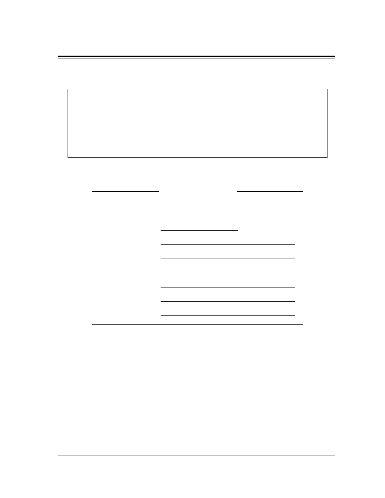
The serial number of this product may be found on the label affixed to the bottom
of the unit. You should note the serial number of this unit in the space provided
and retain this book as a permanent record of your purchase to aid in identification
in the event of theft.
MODEL NO.:
SERIAL NO.:
SERIAL NO.
(found on the bottom of the unit)
DATE OF PURCHASE
NAME OF DEALER
DEALER’S ADDRESS
DEALER’S TEL. NO.
For your future reference
Page 8

8 Introduction
Introduction
This Installation Manual provides technical information for the Panasonic Digital Super
Hybrid System, KX-TD816 / KX-TD1232. It is designed to serve as an overall technical
reference for the system and includes a description of the system, its hardware and software,
features and services and environmental requirements.
This manual contains the following sections:
Section 1, System Outline
Provides general info rm at io n on the syste m includ ing syste m capaci ty and spec ifications.
Section 2, General Installation
Contains the basic system installation and wiring instructions, as well as how to install the
optional cards and units.
Section 3, ISDN Installation
Contains the ISDN unit installation and wiring instructions.
Section 4, E&M Installation
Contains the E&M unit installation and wiring instructions.
Section 5, DECT Installation
Contains the wireless system installation and wiring instructions.
Section 6, Troubleshooting
Provides information for system and telephone troubleshooting.
Section 7, Index
Provides the important words and phrases to help you access the required information easily.
Programming Guide References
The related and req uired programming ti tles described in t he Programming Guide
are noted for
your reference.
Programming Guide reference is also shown in the sentences as follows.
Example: <SYS PRG [109]>
Explanation: Refer to system programme [109] in the Programming Guide.
This helps you know the related and require programming easily for the contents of the
sentences.
Features Guide References
The related feature titles described in the Features Guide
are noted fo r your reference.
About this Installation Manual
Terms used in this Installation Manual
Page 9

Introduction 9
Along with this Instal lation Man ual, the fo llo wing manual s are a v aila ble to hel p you kno w th e
available features, programme and use the KX-TD816 / KX-TD1232 system.
Features Guide
Provides information about the system features.
Programming Guide
Provides system programming instructions.
User Manual
Provides operating instructions for the end users using proprietary telephones, single line
telephones, consoles or DECT portable stations.
About the other manuals
Page 10

10 T able of Contents
Table of Contents
1 System Outline
1.1 S ystem Highlights ........................................................................................................14
1.1.1 System Highlights....................................................................................................... 14
1.2 Basic System Construction .........................................................................................16
1.2.1 Basic System Construction......................................................................................... 16
1.2.2 System Connection Diagram...................................................................................... 17
1.3 P roprietary Telephones............................................................................................... 21
1.3.1 Proprietary Telephones............................................................................................... 21
1.4 Options.......................................................................................................................... 22
1.4.1 Options........................................................................................................................ 22
1.4.2 Expansion Unit Combination ..................................................................................... 25
1.5 S pecifications................................................................................................................ 27
1.5.1 General Description.................................................................................................... 27
1.5.2 Characteristics ............................................................................................................29
1.5.3 System Capacity .........................................................................................................30
2 General Installation
2.1 Before Installation........................................................................................................ 34
2.1.1 Before Installation ...................................................................................................... 34
2.2 Installation of the Main Unit ...................................................................................... 36
2.2.1 Unpacking...................................................................................................................36
2.2.2 Location of Interfaces................................................................................................. 37
2.2.3 Wall Mounting............................................................................................................ 39
2.2.4 Frame Ground Connection ......................................................................................... 41
2.2.5 Opening the Front Cover............................................................................................ 42
2.3 Connection....................................................................................................................43
2.3.1 Outside Line Connection............................................................................................ 43
2.3.2 Extension Connection..................................................................................... ......... ...45
2.3.3 Parallelled Telephone Connection..............................................................................52
2.3.4 EXtra Device Port (XDP) Connection........................................................................ 54
2.3.5 Polarity Sensitive Telephone Connection................................................................... 55
2.3.6 External Pager (Paging Equipment) Connection........................................................57
2.3.7 External Music Source Connection............................................................................ 60
2.3.8 Printer and PC Connection .........................................................................................63
2.3.9 Installation of Lightning Protectors............................................................................ 66
2.4 Installation of Optional Cards and Unit.................................................................... 69
2.4.1 Location of Optional Cards and Units........................................................................ 69
2.4.2 4-CO Line Unit Connection ....................................................................................... 74
2.4.3 8-Station Line Unit Connection.................................................................................. 75
2.4.4 16 SLT Line Circuit Unit............................................................................................ 76
2.4.5 Installing Expansion Unit........................................................................................... 77
2.4.6 Pay Tone Card Installation.......................................................................................... 84
2.4.7 DISA Card / Unit and Remote Card / Unit Installation..............................................87
2.4.8 Doorphone and Door Opener Connection.................................................................. 94
2.4.9 SLT Message Waiting Lamp Adaptor Unit Connection.............................................99
2.4.10 System Connection................................................................................................. 107
Page 11

Table of Contents 11
2.4.11 Battery Adaptor Connection....................................................................................109
2.5 Auxiliary Connection for Power Failure Transfer...................................................112
2.5.1 Auxiliary Connection for Power Failure Transfer.....................................................112
2.6 Closing the Front Cover.............................................................................................114
2.6.1 Closing the Front Cover ............................................................................................114
2.7 Starting the System for the First Time.....................................................................116
2.7.1 Starting the System for the First Time.......................................................................116
2.8 System Restart ............................................................................................................118
2.8.1 System Restart...........................................................................................................118
2.9 System Data Clear......................................................................................................119
2.9.1 System Data Clear.....................................................................................................119
3 ISDN Installation
3.1 ISDN Network Outline...............................................................................................122
3.1.1 Overview ...................................................................................................................122
3.2 ISDN Line Connection...................................................................... .........................123
3.2.1 Location of the Units.................................................................................................123
3.2.2 Installing the Unit......................................................................................................125
3.2.3 Internal ISDN S0 Line Connection ...........................................................................130
4 E & M Installation
4.1 E & M (TIE) Line Service Outline............................................................................134
4.1.1 Overview ...................................................................................................................134
4.1.2 Specifications ............................................................................................................135
4.2 E & M (TIE) Line Installation ..................................................................................136
4.2.1 Location of the Unit...................................................................................................136
4.2.2 Installing the Unit......................................................................................................138
4.2.3 E&M (TIE) Line Connection ....................................................................................142
5 DECT Installation
5.1 Wireless System Outline .......................................................... ..................................148
5.1.1 Overview ...................................................................................................................148
5.1.2 RF Specifications.......................................................................................................149
5.1.3 Procedure Flow Chart................................................................................................150
5.2 Wireless System Installation......................................................................................151
5.2.1 Site Planning..............................................................................................................151
5.2.2 Location of the Unit...................................................................................................154
5.2.3 Installing the Unit......................................................................................................158
5.2.4 Selecting the Display Language................................................................................165
5.2.5 Site Survey.................................................................................................................166
5.2.6 Wall Mounting...........................................................................................................175
6 Troubleshooting
6.1 Troubleshooting ..........................................................................................................178
6.1.1 Installation.................................................................................................................178
6.1.2 Connection.................................................................................................................179
6.1.3 Operation ...................................................................................................................181
6.1.4 Using the Reset Button..............................................................................................182
7 Index .............................................................................................. 185
Page 12

12 T able of Contents
Page 13

System Outline 13
Section 1
System Outline
Page 14
1.1 System Highlights
14 System Outline
1.1 System Highlights
1.1.1 System Highlights
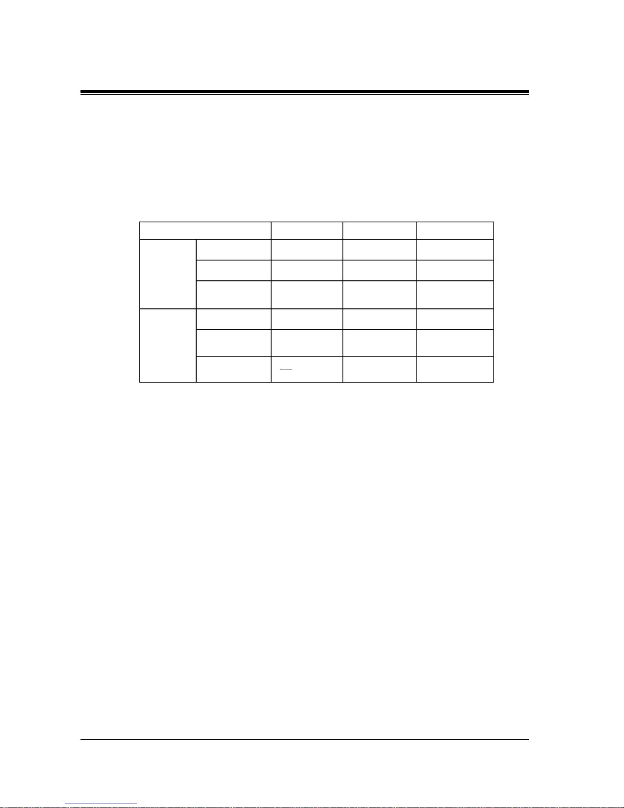
System Maximum Capacity
Module Expansion
Expansion modules are used to increase the system capacity.
EXtra Device Port (XDP)
Each extension jack in the system supports the connection of a digital proprietary telephone /
console and a single line device. The two devices per jack have different extension numbers
and are treated as two completely different extensions.
Parallelled Telephone Connection
Every jack in the system als o supports the paral lel connecti on of a pro prietar y telephone and a
single line de vi ce. The y shar e the same e x tensio n nu mber and are c onsid ered by the syst em to
be one extension.
Super Hybrid System
This system supports the connection of digital and analogue proprietary telephones, DSS
Consoles and single line devices such as single line telephones, fax machines, and data
terminals.
KX-TD816 KX-TD1232 KX-TD1232 x 2
16 (XDP* : 32) 32 (XDP: 64) 64 (XDP: 128)
Extension
12
PT & SLT*
6 BRI (12 ch) 6 BRI (12 ch) 12 BRI (24 ch)ISDN telephone
16 64 64
DECT
portable station
81224
Outside
Line
Analogue
4 BRI (8 ch) 6 BRI (12 ch) 12 BRI (24 ch)
Basic Rate
Interface (BRI)
Primary Rate
Interface (PRI)
1 PRI (30 ch) 1 PRI (30 ch)
* Proprietary telephone and single line telephone
* EXtra Device Port
1
2
Page 15

1.1 System Highlights
System Outline
15
System Connection
*1
With the addition of the optional System Inter Connection Card, two Digital Super Hybrid
Systems can be connected together to double the capacity of the system. The two systems
function as one, therefore, some functions such as paging and music-on-hold are duplicated.
ISDN Line Service
The system can manage a c all rec ei ved from the I SDN line by point-to-po int or po int-to- multipoint configuration. To use this service, an optional unit is required.
E&M (TIE) Line Service
An E&M (TIE) line is a privately leased communication line between two or more PBXs,
which provides cost ef fecti v e communications bet ween compan y at dif ferent location s. To use
this service, an optional unit is required.
Wireless System
The system supports the connection of a DECT portable station which can be used as an
wireless extension. To support the portable station, optional units are required.
*1
A vailable for the KX-TD1232 only.
Page 16
1.2 Basic System Construction
16 System Outline
1.2 Basic System Construction
1.2.1 Basic System Construction
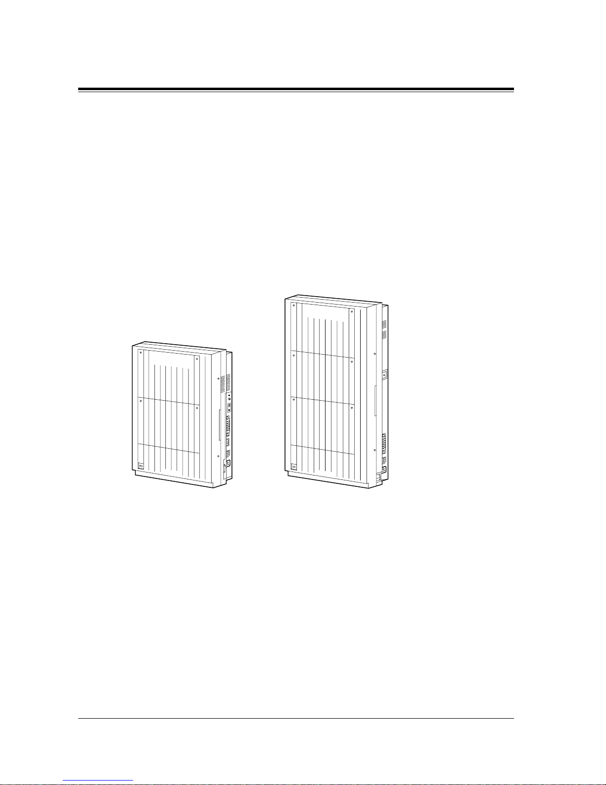
The KX-TD816 Digital Super Hybrid System has a basic capacity of four outside lines and
eight extensions, and the KX-TD1232 has eight outside lines and 16 extensions. They are
capable of supporting Panasonic digital and analogue proprietary telephones, consoles and
single line devices such as single line telephones and fax machines.
To expand its capabilities the system can be equipped with optional components or customersupplied peripherals such as external speakers and external music sources (e.g. radios).
D1232
DIGITAL SUPER HYBRID SYSTEM
Panasonic
Panasonic
D816
DIGITAL SUPER HYBRID SYSTEM
Page 17
1.2 Basic System Construction
System Outline
17
1.2.2 System Connection Diagram
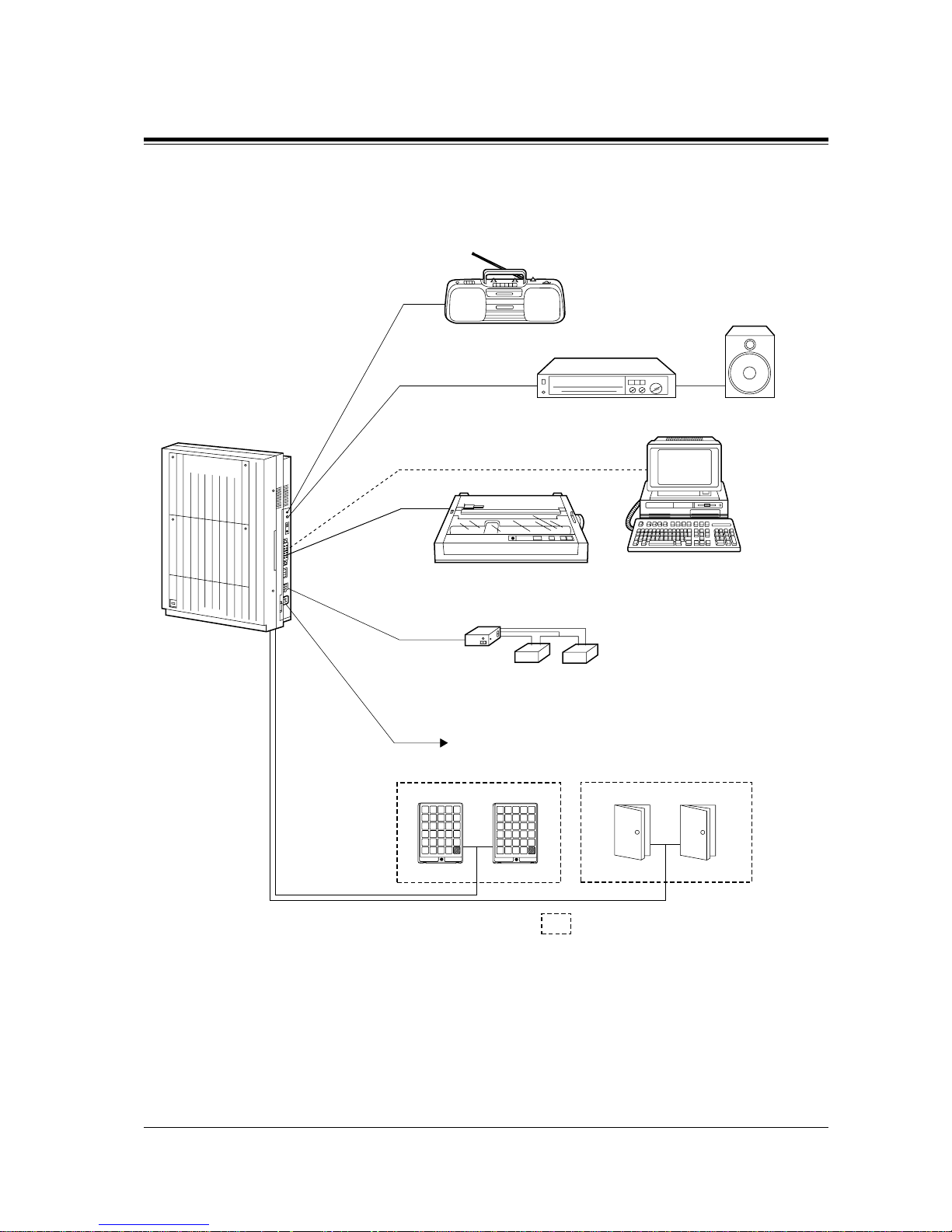
KX-TD816
Panasonic
D816
DIGITAL SUPER HYBRID SYSTEM
Panasonic
Panasonic
Doorphone 1
Doorphone KX-T30865
External Music Source
Amplifier
Printer for SMDR or Personal Computer for System Programming
Battery Adaptor
KX-A46
To AC Outlet
Two car batteries, connected in series
(Consisting of two 12 VDC)
Speaker
Doorphone 2 Door Opener 1 Door Opener 2
: Needs optional unit, card or adaptor.
Page 18
1.2 Basic System Construction
18 System Outline
Note
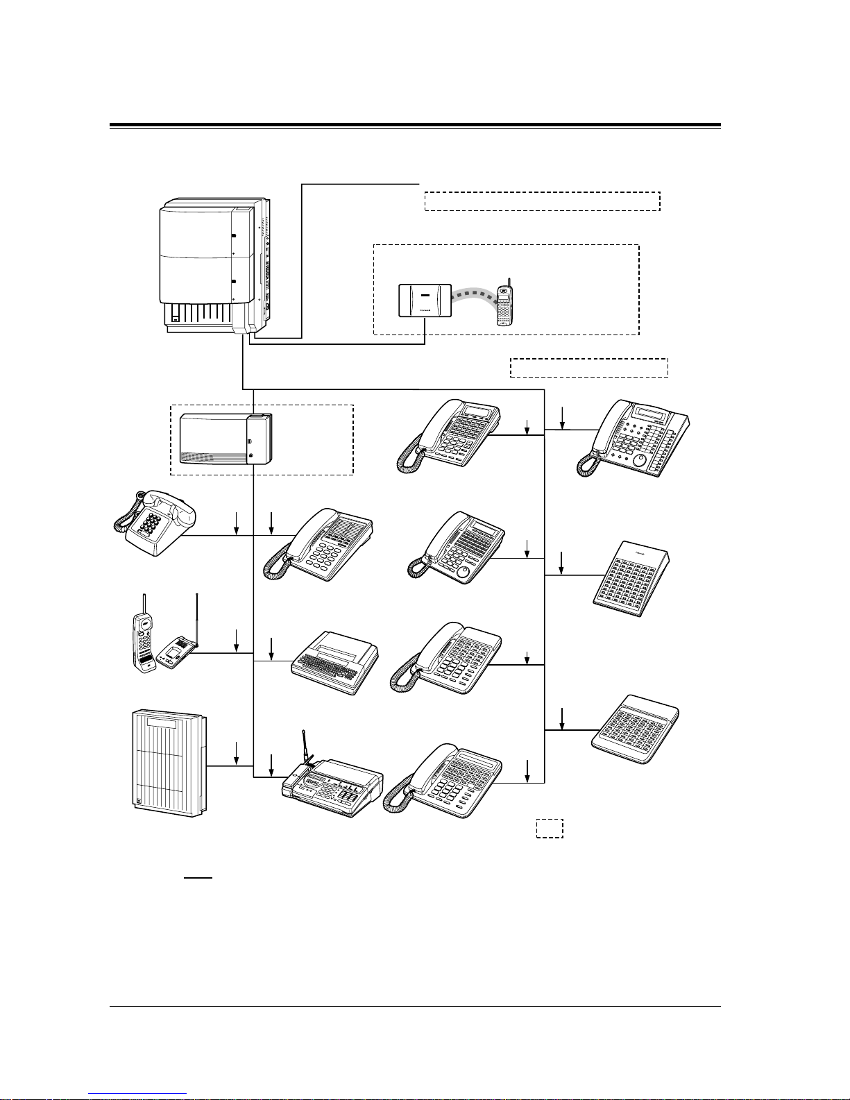
• It is recommended that extension of jack 1 is a display proprietary telephone.
• Parallel conn ection of teleph ones is possible. Ref er to Section 2.3 .3 Parallelled T elephone
Connection.
Panasonic
Panasonic
KX-T7500 series digital
proprietary telephones/
KX-T7545 Add-on Key Module
Digital DSS/Attendant
consoles (KX-T7540/
KX-T7541/KX-T7240)
KX-T7200 series digital
proprietary telephones
(two pair)
Data Terminal
Single Line Telephone
(Lightning Protectors)
to outside lines 1 through 4 (initial)
to outside lines 5 through 8 (additional)
8 Outside Lines
KX-TD142
Cell Station (max.6)
KX-TD7500
DECT portable station
16 Wired extensions (8 extensions - initial, 8 extensions - (additional )
16 Wireless extensions
Cordless Phone
(one pair)
(two pair)
(two pair)
DSS console
(KX-T7340/KX-T7040)
(two pair)
(two
pair)
KX-T7400 series digital
proprietary telephone
KX-T7300 series analogue
proprietary telephone
(two
pair)
(one
pair)
(one
pair)
(one
pair)
(one
pair)
KX-T7000 series analogue
proprietary telephones
(two
pair)
(two
pair)
KX-T7130 analogue
proprietary telephone
Telephone Answering
Machine with Facsimile
Voice Processing System
SLT Message
Waiting Lamp
Adaptor Unit
KX-TD194
DECT
: Needs optional unit,
card or adaptor.
D816
DEGITAL SUPER HYBRID SYSTEM
Panasonic
Page 19
1.2 Basic System Construction
System Outline
19
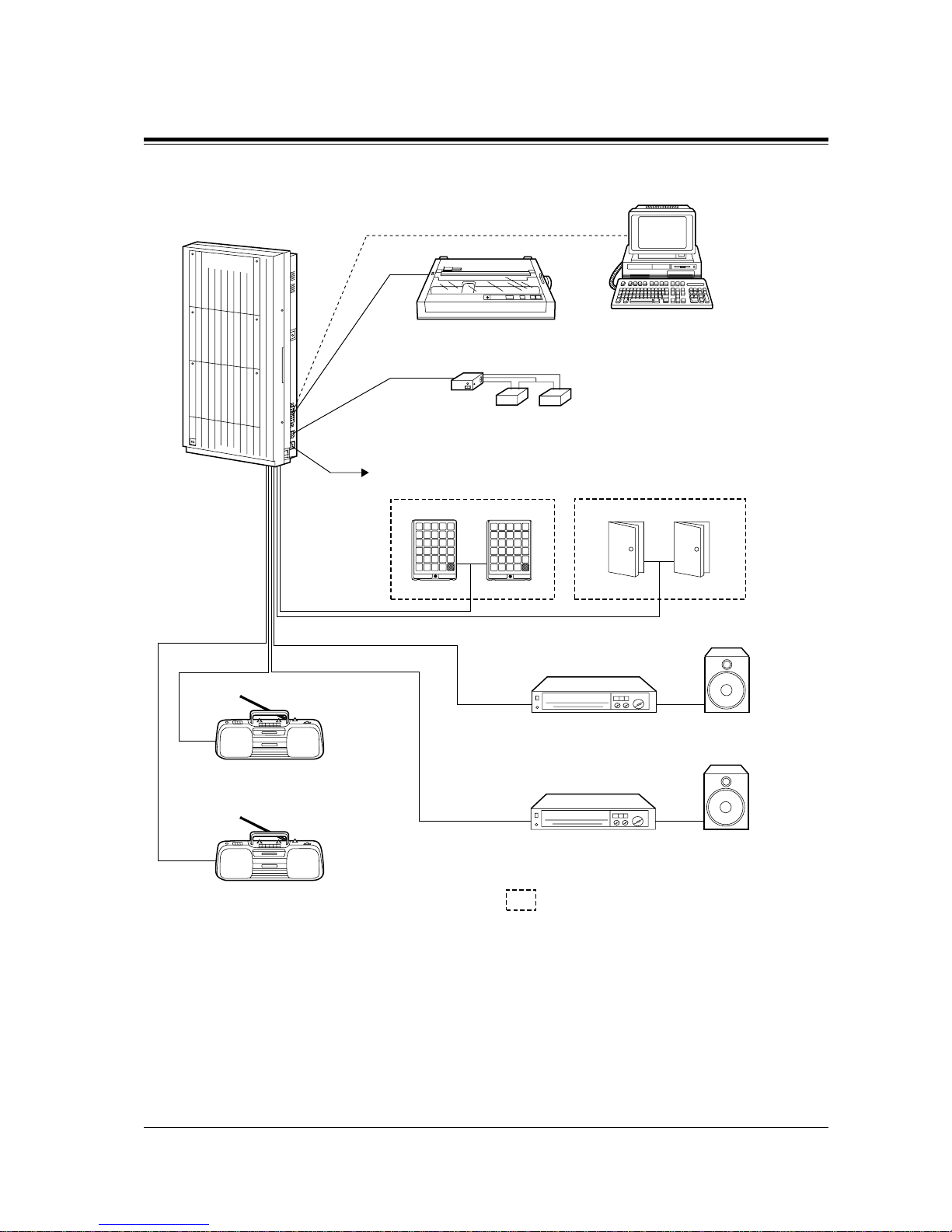
KX-TD1232
D1232
DIGITAL SUPER HYBRID SYSTEM
Panasonic
Panasonic
Panasonic
Doorphone 1
Doorphone KX-T30865
External Music Source 1
Amplifier
Printer for SMDR or Personal Computer for System Programming
Battery Adaptor
KX-A46
To AC Outlet
Two car batteries, connected in series
(Consisting of two 12 VDC)
Speaker 1
Amplifier Speaker 2
External Music Source 2
Doorphone 2 Door Opener 1 Door Opener 2
: Needs optional unit, card or adaptor.
Page 20
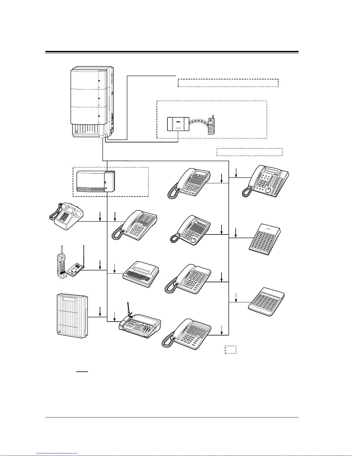
1.2 Basic System Construction
20 System Outline
Note
• It is recommended that extension of jack 1 is a display proprietary telephone.
• Parallel conn ection of teleph ones is possible. Ref er to Section 2.3 .3 Parallelled T elephone
Connection.
Panasonic
Panasonic
KX-T7500 series digital
proprietary telephones/
KX-T7545 Add-on Key Module
Digital DSS/Attendant
consoles (KX-T7540/
KX-T7541/KX-T7240)
KX-T7200 series digital
proprietary telephones
(two pair)
Data Terminal
Single Line Telephone
(Lightning Protectors)
to outside lines 1 through 8 (initial)
to outside lines 9 through 54 (additional)
38 Outside Lines
KX-TD142
Cell Station (max.12)
KX-TD7500
DECT portable station
32 Wired extensions (16 extensions - initial, 16 extensions - additional )
64 Wireless extensions
Cordless Phone
(one pair)
(two pair)
DSS console
(KX-T7340/KX-T7040)
(two pair)
(two
pair)
(two
pair)
(one
pair)
(one
pair)
(one
pair)
(one
pair)
KX-T7000 series analogue
proprietary telephones
(two
pair)
(three
pair)
KX-T7130 analogue
proprietary telephone
Telephone Answering
Machine with Facsimile
Voice Processing System
SLT Message
Waiting Lamp
Adaptor Unit
KX-TD194
D1232
DEGITAL SUPER HYBRID SYSTEM
Panasonic
DECT
: Needs optional unit,
card or adaptor.
(two pair)
KX-T7300 series analogue
proprietary telephone
KX-T7400 series digital
proprietary telephone
Page 21

1.3 Prop r ietary T elephones
System Outline
21
1.3 Proprietary Telephones
1.3.1 Proprietary Telephones
The following Panasonic proprietary telephones are available with this system.
Note
• Flexible CO : Flexible CO buttton (programmab le)
• PF : Programmable Feature button
Proprietary
Telephone
Description
KX-T7520 Digital, speakerphone, Jog Dial, 12 Flexible CO
KX-T7531 Digital, 1-line display, speakerphone, Jog Dial, 12 Flexible CO
KX-T7533 Digital, 3-line display, speakerphone, Jog Dial, 12 Flexible CO
KX-T7536 Digital, 6-line display, speakerphone, Jog Dial, 12 Flexible CO
KX-T7550 Digital, monitor, Jog Dial, 12 Flexible CO
KX-T7425 Digital, speakerphone, Jog Dial, 24 Flexible CO
KX-T7433 Digital, 3-line display, speakerphone, Jog Dial, 24 Flexible CO
KX-T7436 Digital, 6-line display, speakerphone, Jog Dial, 24 Flexible CO
KX-T7450 Digital, monitor, Jog Dial, 12 Flexible CO
KX-T7220 Digital, speakerphone, 24 Flexible CO
KX-T7230 Digital, 2-line display, speakerphone, 24 Flexible CO
KX-T7235 Digital, 6-line display, speakerphone, 12 Flexible CO
KX-T7250 Digital, monitor, 6 Flexible CO
KX-T7320 Speakerphone, 12 Flexible CO
KX-T7330 1-line displ ay, speakerpho ne, 12 Flexible CO
KX-T7350 Monitor, 12 Flexible CO
KX-T7130 1-line display, speakerphone, 12 Flexible CO, 12 PF
KX-T7020 Speakerphone, 12 Flexible CO, 4 PF
KX-T7030 1-line display, speakerphone, 12 Flexible CO, 4 PF
KX-T7033 1-line display, speakerphone, 12 Flexible CO, 4 PF
KX-T7050 Monitor, 12 Flexible CO, 4 PF
KX-T7055 Monitor, 3 Flexible CO, 4 PF
KX-TD7500 Digital, wireless, 3 Flexible CO
Page 22

1.4 Options
22 System Outline
1.4 Options
1.4.1 Options
Model No. Model Name Description
Max.
Quantity
on
KX-
TD816
Max. Quantity on
KX-TD1232
Single
System
System
Connection
KX-TD170 8-Station Line Unit Adds 8 extension lines. 1 2 4
KX-TD174 16 SLT Line Circuit
Unit
Adds 16 extension lines
which contain single
line telephones.
12 4
KX-TD180 4-CO Line Unit Adds 4 outside lines. 1 1 2
KX-TD184 E&M (TIE) Line
Unit
Adds 4 ports for E&M
Line Service.
11 2
KX-TD280 2-ISDN S0 Line Unit Adds 2 ISDN S0 lines. 1 1 2
KX-TD286 6-ISDN S0 Line Unit Adds 6 ISDN S0 lines. 1 1 2
KX-TD290 Primary Rate
Interface ISDN
Expansion Unit
Adds 1 PRI ISDN line. — 1 1
KX-TD144 Cell Station Interface
Unit
Supports up to two Cell
Stations (KX-TD142).
12 2
KX-TD146 Cell Station Interface
Unit
Supports up to six Cell
Stations (KX-TD142).
12 2
KX-TD142 Cell Station Determines the range of
the supporting DECT
Portable Station (KXTD7500). Up to four
calls can be made at the
same time in one rang e.
(6 per Cell
Station
Interface
Unit)
(6 per Cell
Station
Interface
Unit)
(6 per Cell
Station
Interface
Unit)
KX-TD189 Pay Tone Card Supports the Pay Tone
service of the central
office.
2* 3* 6*
KX-TD190 DISA Unit Supports the Direct
Inward System Access
(DISA) feature and
records outgoing
messages.
1— —
Page 23

1.4 Options
System Outline
23
KX-TD191 DISA Card Supports the Direct
Inward System Access
(DISA) feature and
records outgoing
messages.
—1 2
KX-TD192 System Inter
Connection Card
Connects two Digital
Super Hybrid Systems.
—— 2
KX-TD194 SLT Message
Waiting Lamp
Adaptor Uni t
Supports the Message
Waiting feature for a
single line telephone
with a message wait ing
lamp. One unit supports
16 extensions.
13 6
KX-TD196 Remote Card Supports the
programming and
maintenance of the
system from a remote
location.
—1 2
KX-TD197 High Speed Remote
Card
Supports the
programming and
maintenance of the
system from a remote
location. This card can
also be installed in the
KX-TD190, DISA
Unit, for the KXTD816.
(1 per
KX-
TD190)
12
KX-TD198 Remote Unit Supports the
programming and
maintenance of the
system from a remote
location.
1— —
KX-TD199 DISA Card Supports the Direct
Inward System Access
(DISA) feature and
records an Outgoing
Message. This card can
only be installed in the
KX-TD198, Remote
Unit.
(1 per
KX-
TD198)
——
Model No. Model Name Description
Max.
Quantity
on
KX-
TD816
Max. Quantity on
KX-TD1232
Single
System
System
Connection
Page 24

1.4 Options
24 System Outline
* One KX-TD189 can be connected to every four CO (outside line) ports.
KX-TD160 Doorphone Card Supports 2 doorphones
(KX-T30865) and 2
door openers.
11 2
KX-A277 AC Adaptor Required when
installing the Cell
Station Interface Unit,
KX-TD146.
—— —
KX-A46 Battery Adaptor Supports the connection
of two car batteries for
power backup in the
event of a power failure.
11 2
KX-T7540 /
KX-T7440 /
KX-T7240
Digital DSS Console Provides easy and quick
access to extens ions and
features. This must be
used with a proprietary
telephone.
44 8
KX-T7541 Digital Attendant
Console
KX-T7441 DSS Console for
Attendant
KX-T7040 /
KX-T7340
DSS Console
KX-T7545 Add-on Key Module Adds 12 CO buttons to
a KX-T7500 series
digital proprietary
telephone.
—— —
KX-T30865 Doorphone Used for a doorphone
call.
22 4
Model No. Model Name Description
Max.
Quantity
on
KX-
TD816
Max. Quantity on
KX-TD1232
Single
System
System
Connection
Page 25
1.4 Options
System Outline
25
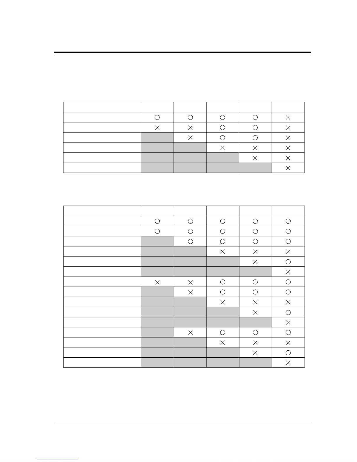
1.4.2 Expansion Unit Combination
KX-TD816
KX-TD1232 Master System
Basic (no unit connected)
KX-TD14x
KX-TD17x
KX-TD18x
KX-TD28x
KX-TD290
KX-TD28xKX-TD18xKX-TD17xKX-TD14x KX-TD290
Basic (no unit connected)
KX-TD14x
KX-TD17x
KX-TD18x
KX-TD28x
KX-TD290
KX-TD14x + KX-TD14x
KX-TD14x + KX-TD17x
KX-TD14x + KX-TD18x
KX-TD14x + KX-TD28x
KX-TD14x + KX-TD290
KX-TD17x + KX-TD17x
KX-TD17x + KX-TD18x
KX-TD17x + KX-TD28x
KX-TD17x + KX-TD290
KX-TD28xKX-TD18xKX-TD17xKX-TD14x KX-TD290
Page 26
1.4 Options
26 System Outline
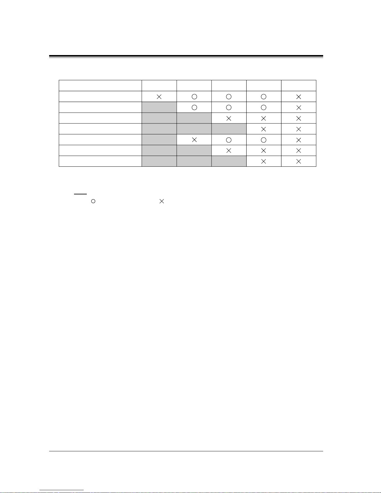
KX-TD1232 Slave System
Note
• : Combination possible; : Combination not possible;
Shaded part: These combinations shown elsewhere in the table.
x: Any number (e.g. KX-TD28x can be KX-TD280 or KX-TD286)
• The KX-TD14x and KX-TD290 can only be connected to the Master system.
• If the KX-TD290 is connected, no outside lines on the Slave system can be used.
Basic (no unit connected)
KX-TD17x
KX-TD18x
KX-TD28x
KX-TD17x + KX-TD17x
KX-TD17x + KX-TD18x
KX-TD17x + KX-TD28x
KX-TD28xKX-TD18xKX-TD17xKX-TD14x KX-TD290
Page 27
1.5 Specifications
System Outline
27
1.5 Specif ications
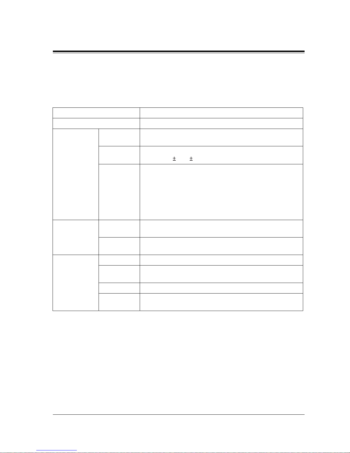
1.5.1 General Description
Control Method CPU: 16-bit CPU
Switching Non Blocking PCM Time Switch
Power Supplies Primary KX-TD816: 220 VAC – 230 VAC, 50 Hz
KX-TD1232: 220 – 240 VAC, 50 Hz / 60 Hz
Secondary Station Supply Volt: 30 V
Circuit Volt: 5 V, 15 V
Power F ai l ure • Memory backup duration: seven years with a factory-provided
lithium battery
• 4 outside lines max. for KX-TD816 and 6 out si de l ines max. f or
KX-TD1232 automatically a ssigned to extensions (Po wer Failure
Trans fer)
• System operation for about three hours using recommended
batteries (consisting of two 12 VDC car batteries)
Dialling Outward Dial Pulse (DP) 10 pps, 20 pps
Tone (DTMF) Dialling
Internal Dial Pulse (DP) 10 pps, 20 pps
Tone (DTMF) Dialling
Connectors Outside lines Modular Jack
Extensions KX-TD816: Modular Jack
KX-TD1232: Amphenol Connector
Paging Output Pin Jack (RCA JACK)
External
Music Input
Two-conductor Jack (MINIJACK 3.5 mm diameter)
Page 28
1.5 Specifications
28 System Outline
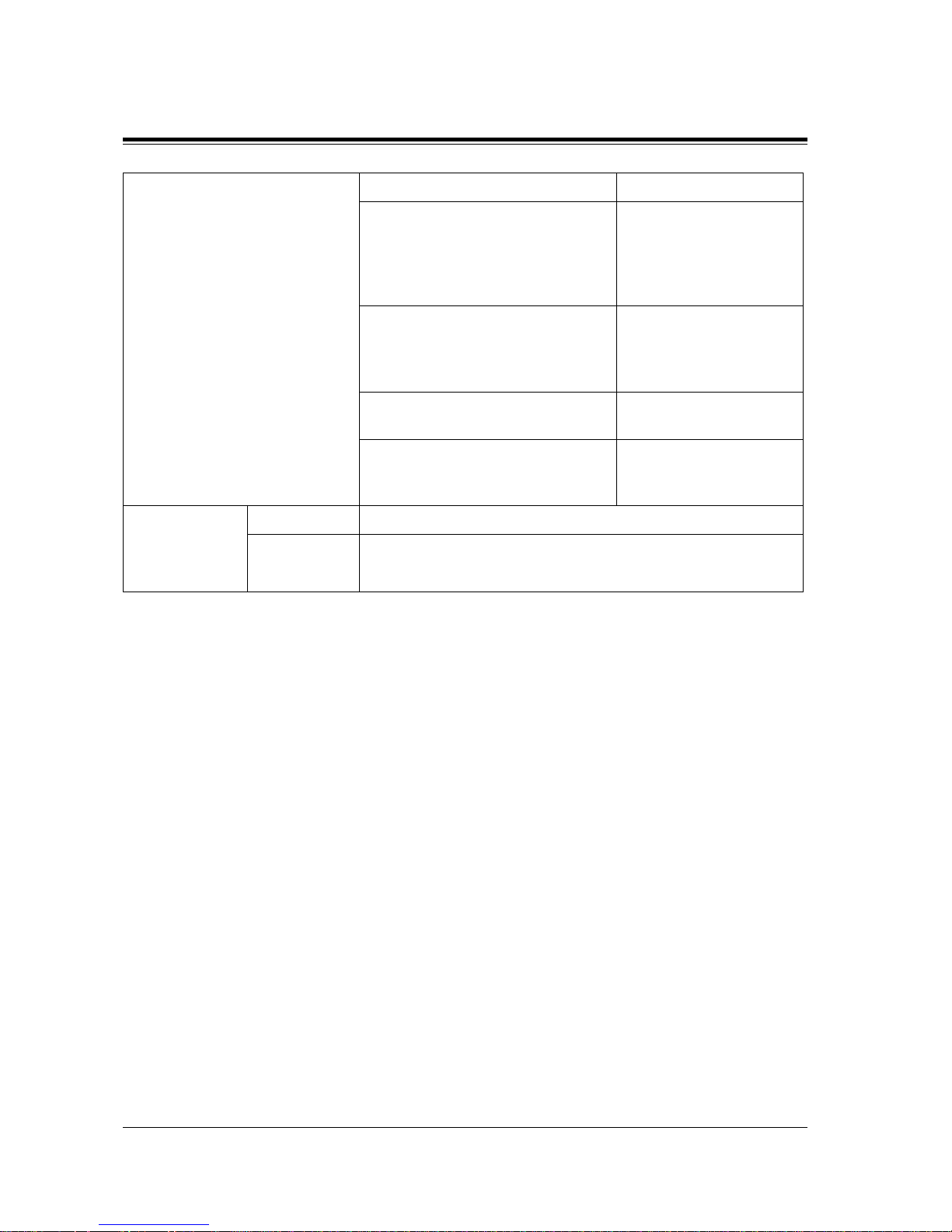
Extension Connection Cable Single line telephones 1 pair wire (T, R)
KX-T7520, KX-T7531, KX-T7533,
KX-T7536, KX-T7550, KX-T7425,
KX-T7433, KX-T7436, KX-T7450,
KX-T7220, KX-T7230, KX-T7235,
KX-T7250
1 pair wire (D1, D2) or
2 pair wire (T, R, D1, D2)
KX-T7320, KX-T7330, KX-T7350,
KX-T7130 (with the KX-TD816),
KX-T7020, KX-T7030, KX-T7033,
KX-T7050, KX-T7055
2 pair wire (T, R, D1, D2)
KX-T7130 (with the KX-TD1232) 3 pair wire (T, R, D1, D2,
P1, P2)
KX-T7540, KX-T7541, KX-T7440,
KX-T7441, KX-T7240, KX-T7340,
KX-T7040
1 pair wire (D1, D2)
Station
Message Detail
Recording
(SMDR)
Interface Serial Interface (RS-232C)
Output
Equipment
Printer
Page 29
1.5 Specifications
System Outline
29
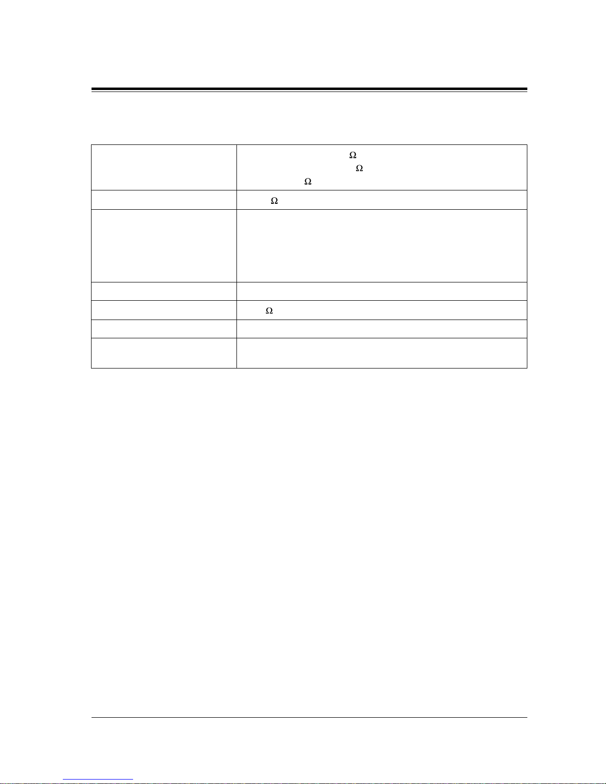
1.5.2 Characteristics
Station Loop Limit
Proprietary Telephone: 40
Single Line Telephone: 600 including set
Doorphone: 20
Minimum Leakage Resistance
15 000
Maximum Number of Station
Instruments per Line
1 for proprietary telephone or single line telephone
2 by Parallel or eXtra Device Port Connection of a proprietary
telephone and a single line telephone or
by Super eXtra Device Port Connection of a wired telephone
(proprietary or single line telephone) and a DECT portable station
Ring Voltage 70 Vrms at 25 Hz depending on the Ringing Load
Central Office Loop Limit
1 600 max.
Environmental Requirements 0°C – 40°C, 10 – 90% relative humidity
Hookswitch Flash Timing
Range
84 ms –1000 ms
Page 30
1.5 Specifications
30 System Outline
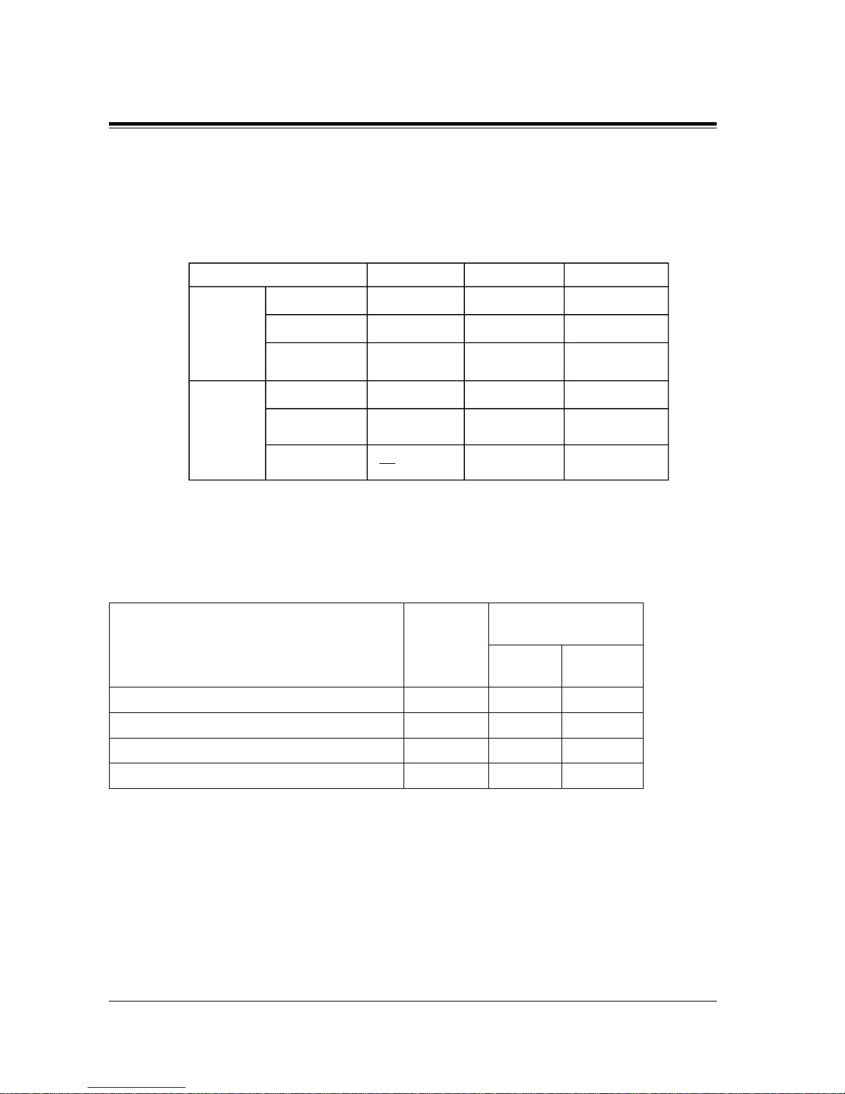
1.5.3 System Capacity
Line
Actual capacity will depend on the number or/and type of units connected to the system.
User-supplied Equipment
Item Max.
Quantity on
KX-TD816
Max. Quantity on
KX-TD1232
Single
System
System
Connection
Doorphones 2 2 4
Door Openers 2 2 4
External Pagers 1 2 4
External Music Source 1 2 4
KX-TD816 KX-TD1232 KX-TD1232 x 2
16 (XDP* : 32) 32 (XDP: 64) 64 (XDP: 128)
Extension
12
PT & SLT*
6 BRI (12 ch) 6 BRI (12 ch) 12 BRI (24 ch)ISDN telephone
16 64 64
DECT
portable station
81224
Outside
Line
Analogue
4 BRI (8 ch) 6 BRI (12 ch) 12 BRI (24 ch)
Basic Rate
Interface (BRI)
Primary Rate
Interface (PRI)
1 PRI (30 ch) 1 PRI (30 ch)
* Proprietary telephone and single line telephone
* EXtra Device Port
1
2
Page 31

1.5 Specifications
System Outline
31
System Data
Item Max. Quantity
Operators 2
System Speed Dialling 500
One-Touch Dialling 24 per extension
(proprietary telephone)
Station Speed Dialling 10 per extension
Call Park areas 10
Absent Messages 9
Outside Line Groups 8
Toll Restriction Levels 8
Extension Groups 8
Class of Service 8
Message Waitings 128
Uniform Call Distribution Groups 8
Page 32

1.5 Specifications
32 System Outline
Page 33

General Installation 33
Section 2
General Installation
Page 34

2.1 Before Installation
34 General Installation
2.1 Before Installation
2.1.1 Before Installation
Please read the following notes concerning installation and connection before installing the
system and terminal equipment.
Safety Installation Instructions
When installing telephone wiring, basic safety precautions should always be followed to
reduce the ris k of fire, electric shock and injury to persons, including the following:
a) Never install telephone wiring during a lightning storm.
b) Ne ver install telephone jacks in wet locations unless the jack is specifically designed for
wet locations.
c) Never to uch uninsulat ed telephone wires or te rminals unle ss the telepho ne line has been
disconnected at the network interface.
d) Use caution when installing or modifying telephone lines.
Installation Precautions
This system is designed for wall mounting only. Avoid installing in the following places.
(Doing so may result in malfunction, noise, or discoloration.)
a) In direct sunlight and hot, cold, or humid places. (Temperature range: 0°C – 40°C)
b) Sulfuric gases produced in areas where there are thermal springs, etc. may damage the
equipment or contacts.
c) Places in which shocks or vibrations are frequent or strong.
d) Dusty places, or places where water or oil may come into contact with the system.
e) Near high-frequency generating devices such as sewing machines or electric welders.
f) On or near computers, tele xes , or other of f ice equipment , as well as micr ow av e ov ens or
air conditioners. (It is preferable not to install the sys tem in the same ro om with the
above equipment.)
g) Install at least 1.8 m away from radios and televisions. (Bot h the system and Panaso nic
proprietary telephones)
h) Do not obstruct area around the system (for reasons of maintenance and inspection —
be especially careful to allow space for cooling above and at the sides of the system).
Page 35
2.1 Before Installation
General Installation
35
Wiring Precautions
Be sure to follow these instructions when w iring the unit:
a) Do not wire the telephone cable in parallel with an AC power source, computer, telex,
etc. If the cables are run near those wires, shield the cables with metal tubing or use
shielded cables and ground the shields.
b) If c ables are run on the floor, use protectors to pre v ent t he wires from be ing s tepped on.
Avoid wiring under carpets.
c) Avoid using the same power supply outlet for computers, telexes, and other office
equipment. Otherwise, the system operation may be interrupted by the induction noise
from such equipment.
d) Please use one pair telephone wire for extension connection of (telephone) equipment
such as single line telephones, data terminals, answering machines, computers, voice
processing systems, etc ., exc ept P anasonic pr oprietary t elephones ( e.g. KX-T7536, KXT7235).
e) The Power Switch of the system must be off during wiring. After all of the wiring is
completed, turn the Power Switch on.
f) Mis-wiring may cause the system to operate improperly. Refer to Section
6.1.1 Installation and 6.1.2 Connection.
g) If an extension does not operate properly, disconnect the telephone from the extension
line and then connect again, or turn off the Power Switch of the system and then on
again.
h) The system is equipped with a 3-wire grounding type plug. This is a safety feature. If
you are unable to insert the plug into t he out let, contact your ele ct rici an to replace your
obsolete outlet. Do not defeat the purpose of the grounding-type plug.
i) Use twisted pair cable for outside line connection.
j) Outside lines should be installed with lightning protectors. For details, refer to Section
2.3.9 Installation of Lightning Protectors.
WARNING
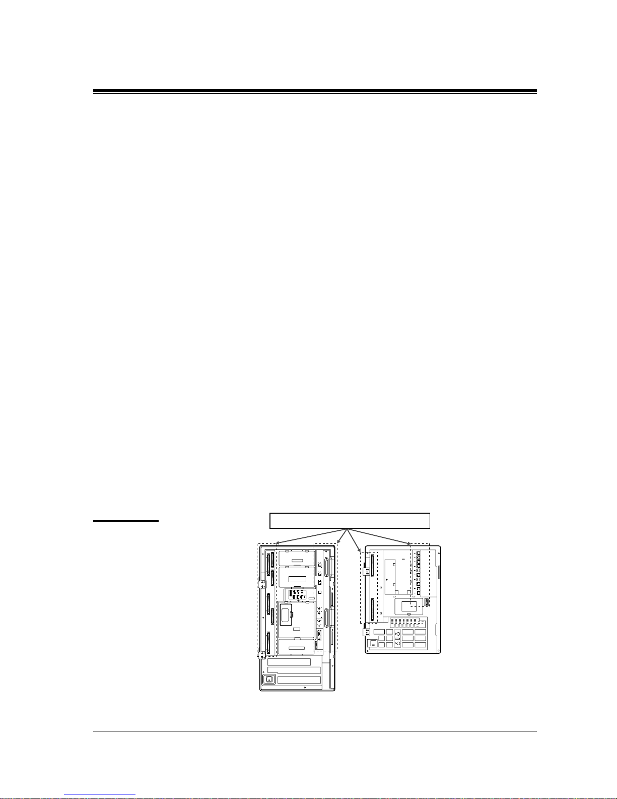
Static sensitiv e de vices ar e used. To
protect printed cir cuit boards fr om
static electricity, do not touch
connectors indicated to the right.
To discharge body static, touch
ground or wear a grounding strap.
Warning: Static sensitive connectors
KX-TD1232
KX-TD816
Page 36

2.2 Installation of the Main Unit
36 General Installation
2.2 Installation of the Main Unit
2.2.1 Unpacking
Unpack the box and check the items below:
KX-TD816 KX-TD1232
Main Unit one one
AC Cord one one
Template one one
Screws (Wall Mounting) three four
Anchor Plu g three four
Pager Connectors — two
Music Source Connectors — two
Expansion Line Cord Holder one one
Page 37
2.2 Installation of the Main Unit
General Installation
37
2.2.2 Location of Interfaces
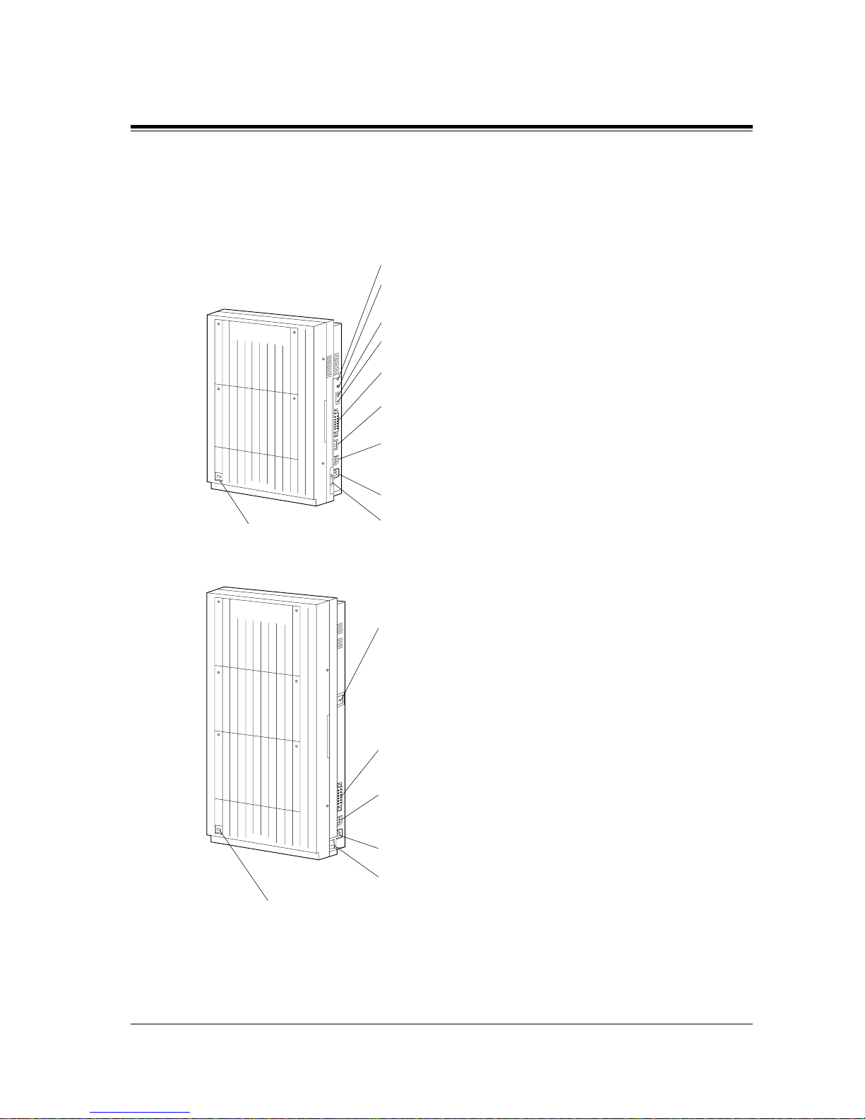
Overview
KX-TD816
KX-TD1232
D816
DIGITAL SUPER HYBRID SYSTEM
Panasonic
External Music Jack
Paging Jack
System Clear Switch
Reset Button
Serial Interface
(RS-232C) Connector
Ground Terminal
Battery Adaptor
Connector
AC Inlet
Power Switch
Power Indicator
D1232
DIGITAL SUPER HYBRID SYSTEM
Panasonic
Serial Interface
(RS-232C) Connector
Ground Terminal
Battery Adaptor
Connector
AC Inlet
Power Switch
Power Indicator
Page 38
2.2 Installation of the Main Unit
38 General Installation
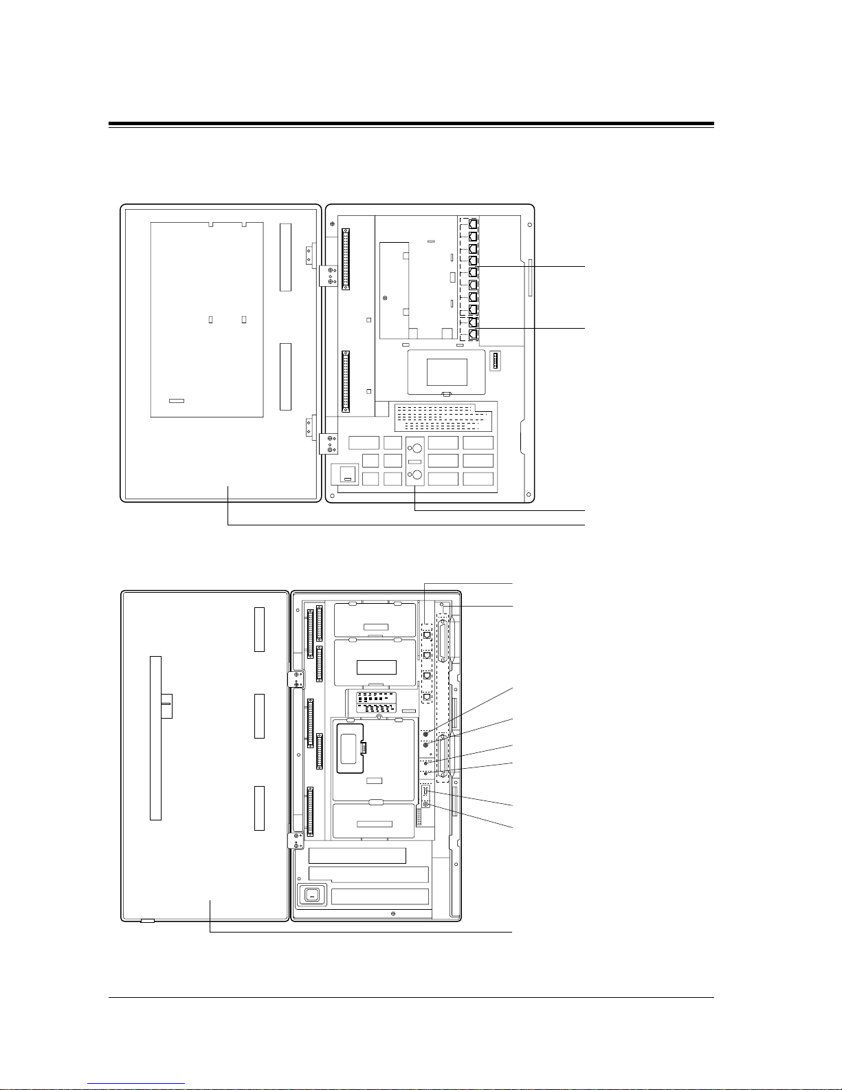
Inside View
KX-TD816
KX-TD1232
Extension Modular
Jacks
Outside Line
Modular Jacks
Fuse
Front Cover
Outside Line Modular Jacks
Extension Amphenol Connectors
Paging Jack 2
Paging Jack 1
External Music Jack 2
External Music Jack 1
System Clear Switch
Reset Button
Front Cover
Page 39
2.2 Installation of the Main Unit
General Installation
39
2.2.3 Wall Mounting
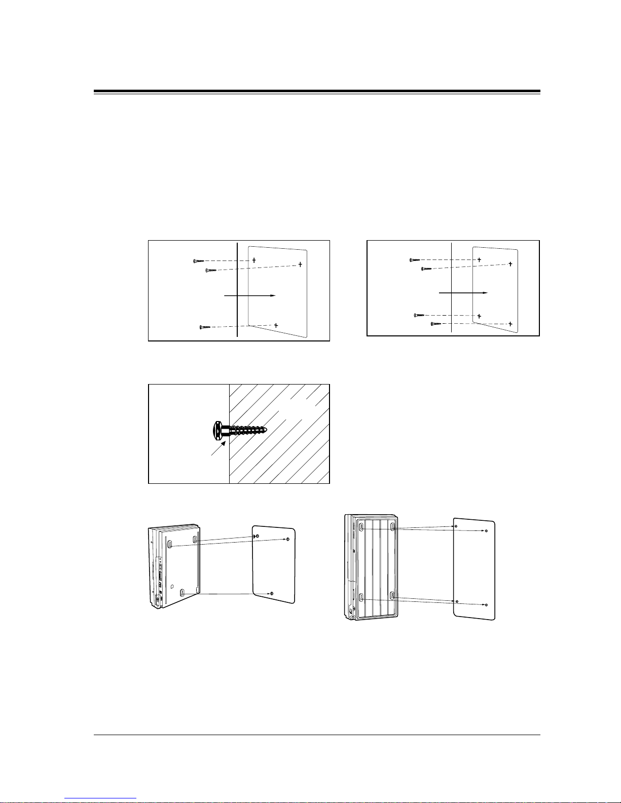
This set is designed for wall mounting only. The wall where the main unit is to be mounted
must be able to support the weight of the main unit . If screws other than the ones supplied are
used, use screws with the same diameter as the ones enclosed.
Mounting on Wooden Wall
1. Place the template (included) on the wall to mark the screw positions.
2. Install the screws (inc lud ed) into the wall.
3. Hook the main unit on the screw heads.
Template
Template
KX-TD816 KX-TD1232
Drive the screw
to this position
Wooden
Wall
KX-TD816 KX-TD1232
Page 40
2.2 Installation of the Main Unit
40 General Installation
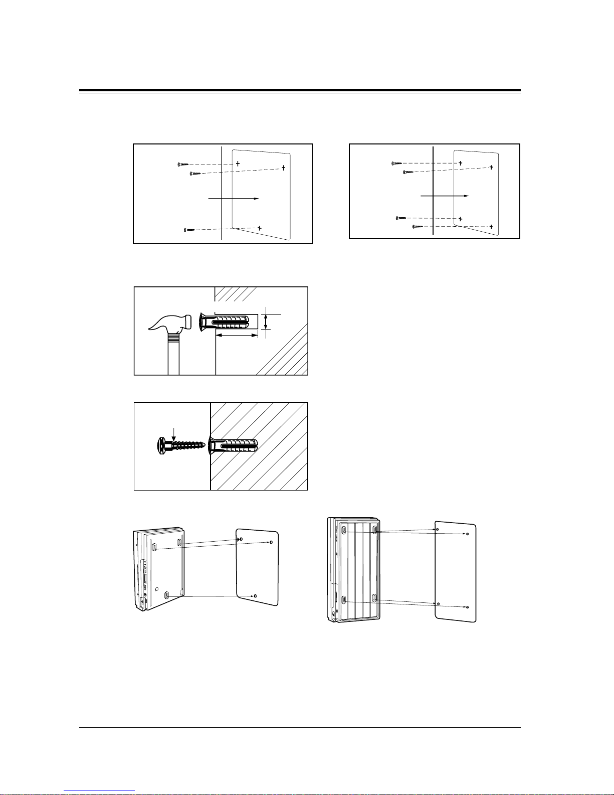
Mounting on Concrete or Mortar Wall
1. Place the template (included) on the wal l to mark the screw positions.
2. Drill holes and drive the anchor plugs (included) with a hammer, flush to the wall.
3. Install the screws (included) into the anchor plugs.
4. Hook the main unit on the screw heads.
Template
Template
KX-TD816 KX-TD1232
Concrete Wall
To the wall surface
Anchor Plug
29 mm
6.4 mm
Drive the screw
to this position
KX-TD816 KX-TD1232
Page 41
2.2 Installation of the Main Unit
General Installation
41
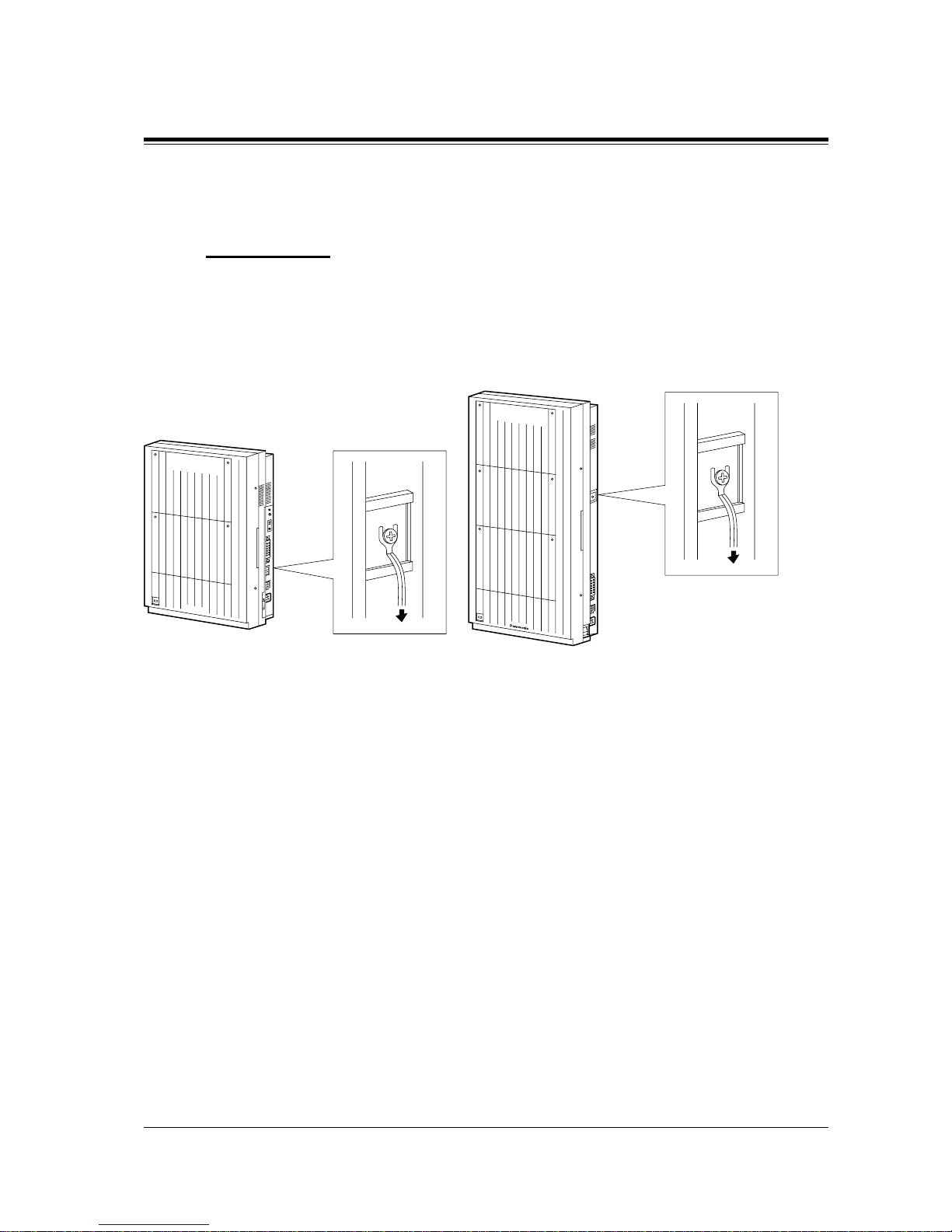
2.2.4 Frame Ground Connection
IMPORTANT
Connect the frame of the main unit to ground.
1. Loosen the screw.
2. Insert the grounding wire.
3. Tighten the screw.
4. Connect the grounding wire to ground.
To ground
Panasonic
D816
DIGITAL SUPER HYBRID SYSTEM
To ground
D1232
DIGITAL SUPER HYBRID SYSTEM
Page 42
2.2 Installation of the Main Unit
42 General Installation
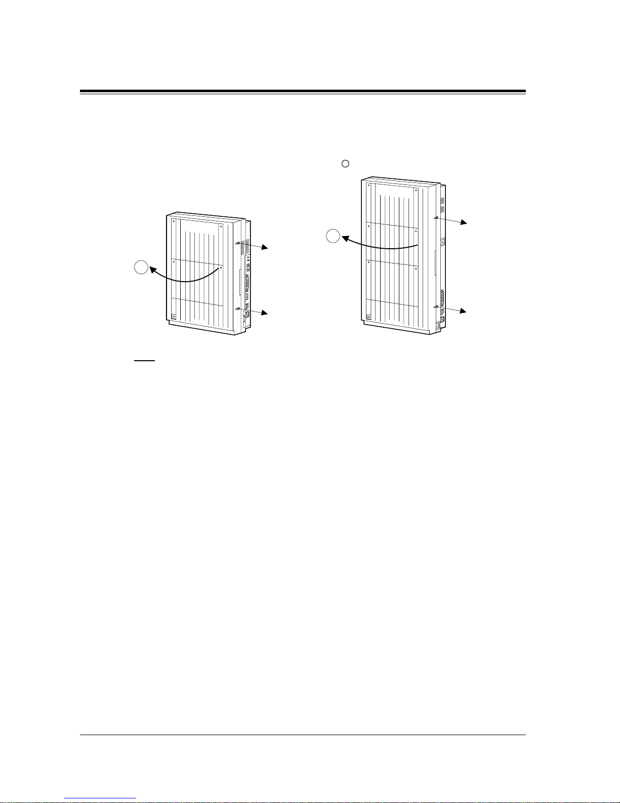
2.2.5 Opening the Front Cover
1. Loosen the two screws on the right side of the main unit.
2. Open the front cover in the direction of a rrow .
Note
The two screws are attached to the front cover with springs so that they will not be lost.
A
D1232
DIGITAL SUPER HYBRID SYSTEM
Panasonic
A
Panasonic
D816
DIGITAL SUPER HYBRID SYSTEM
A
screw
screw
screw
screw
Page 43
2.3 Connection
General Installation
43
2.3 Connection
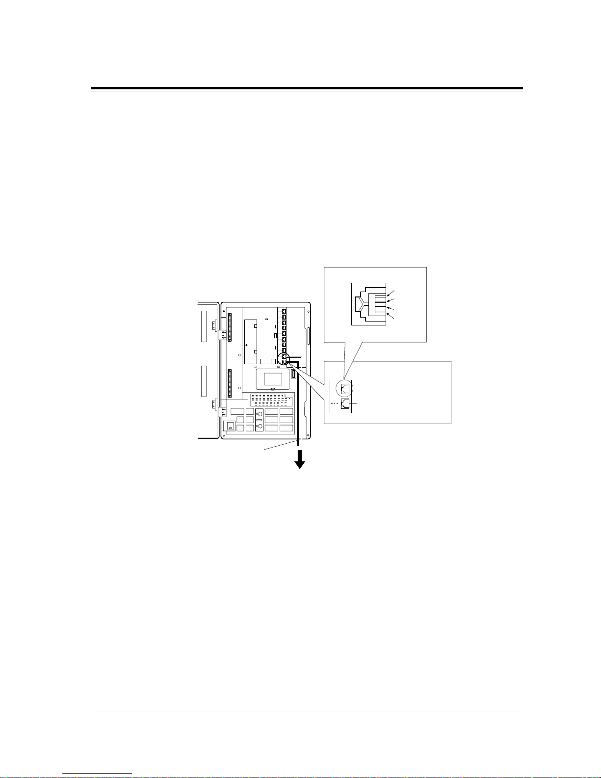
2.3.1 Outside Line Connection
Connection
1. Insert the modular plugs of t h e te le phone line cords (4-conduct or wi ring) into the modular
jacks on the system.
2. Connect the line cord to the terminal board or the Cent ral Office jack.
KX-TD816
(T1, R1) (T2, R2)
Outside Line
03,
Outside Line
04
Outside Line
01,
Outside Line
02
T2
R1
T1
R2
View of TEL Jack (Outside Line)
R: Ring T: Tip
Use 4-conductor wiring cord
To Terminal Board or Modular
Jacks from the Central Office.
Page 44
2.3 Connection
44 General Installation
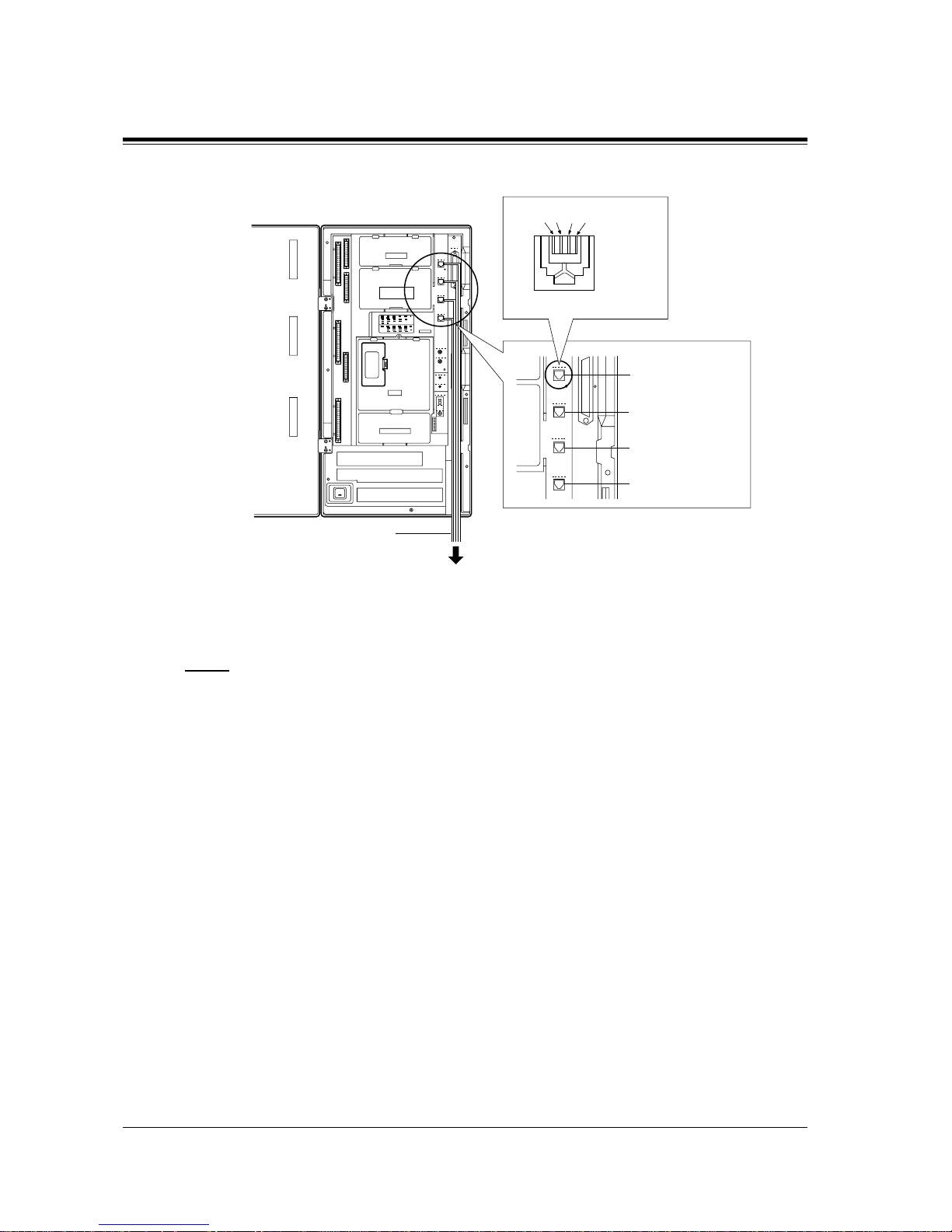
KX-TD1232
Notice
• Use twisted pair cable for installation.
• Mis-connection may cause the system to operate improperly. See Section
6.1.1 Installation and 6.1.2 Connection.
Outside Line 01, Outside Line 02
Outside Line 03, Outside Line 04
Outside Line 05, Outside Line 06
Outside Line 07, Outside Line 08
(T1, R1) (T2, R2)
R: Ring
T: Tip
T2 R1 T1 R2
View of TEL Jack (Outside Line)
Use 4-conductor wiring cord
To Terminal Board or Modular
Jacks from the Central Office.
Page 45
2.3 Connection
General Installation
45
2.3.2 Extension Connection
KX-TD816
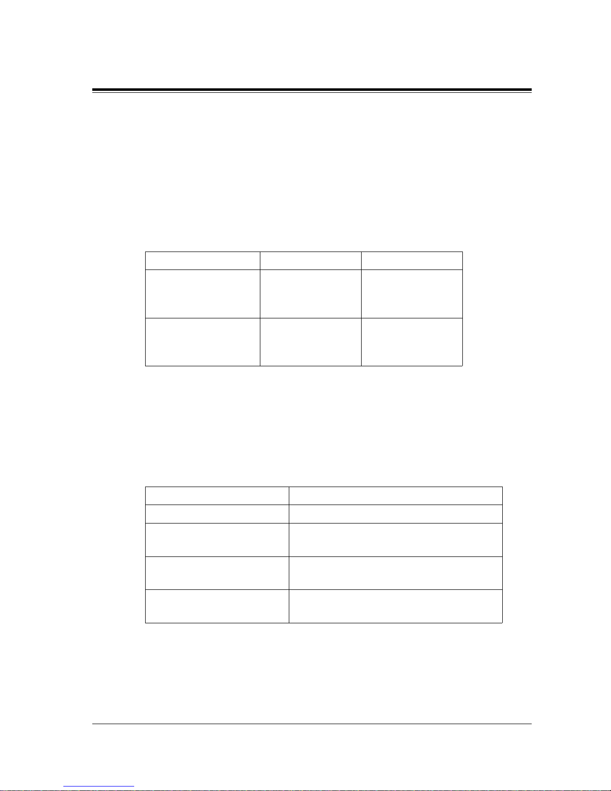
Extension jacks 01 through 08 are for all kinds of telephones.
Maximum Cabling Distance
The maximum length of the e xtension line cord (t wisted cable ) which connects t he system and
the extension is as follows:
Telephone Wiring
2 or 4-conductor wiring is required for each extension as listed below. There are four pins for
possible connection: "T", "R", "D1" and "D2".
T: Tip
R: Ring
D1: Data 1
D2: Data 2
Diameter of the line Max. length
Single Line Telephone 22 AWG
24 AWG
26 AWG
1798 m
1128 m
698 m
Proprietary Telephone /
Console
22 AWG
24 AWG
26 AWG
360 m
229 m
140 m
Telephone Wiring
Single Line telephone 1 pair wire (T, R)
Digital proprietary telephone
(e.g. KX-T7536, KX-T7235)
1 pair wire (D1, D2) or
2 pair wire (D1, D2, T, R) for eXtra Device Port
Analogue proprietary telephone
(e.g. KX-T7030, KX-T7130)
2 pair wire (D1, D2, T, R)
Console
(e.g. KX-T7540, KX-T7240)
1 pair wire (D1, D2)
Page 46
2.3 Connection
46 General Installation
Connection
KX-TD1232
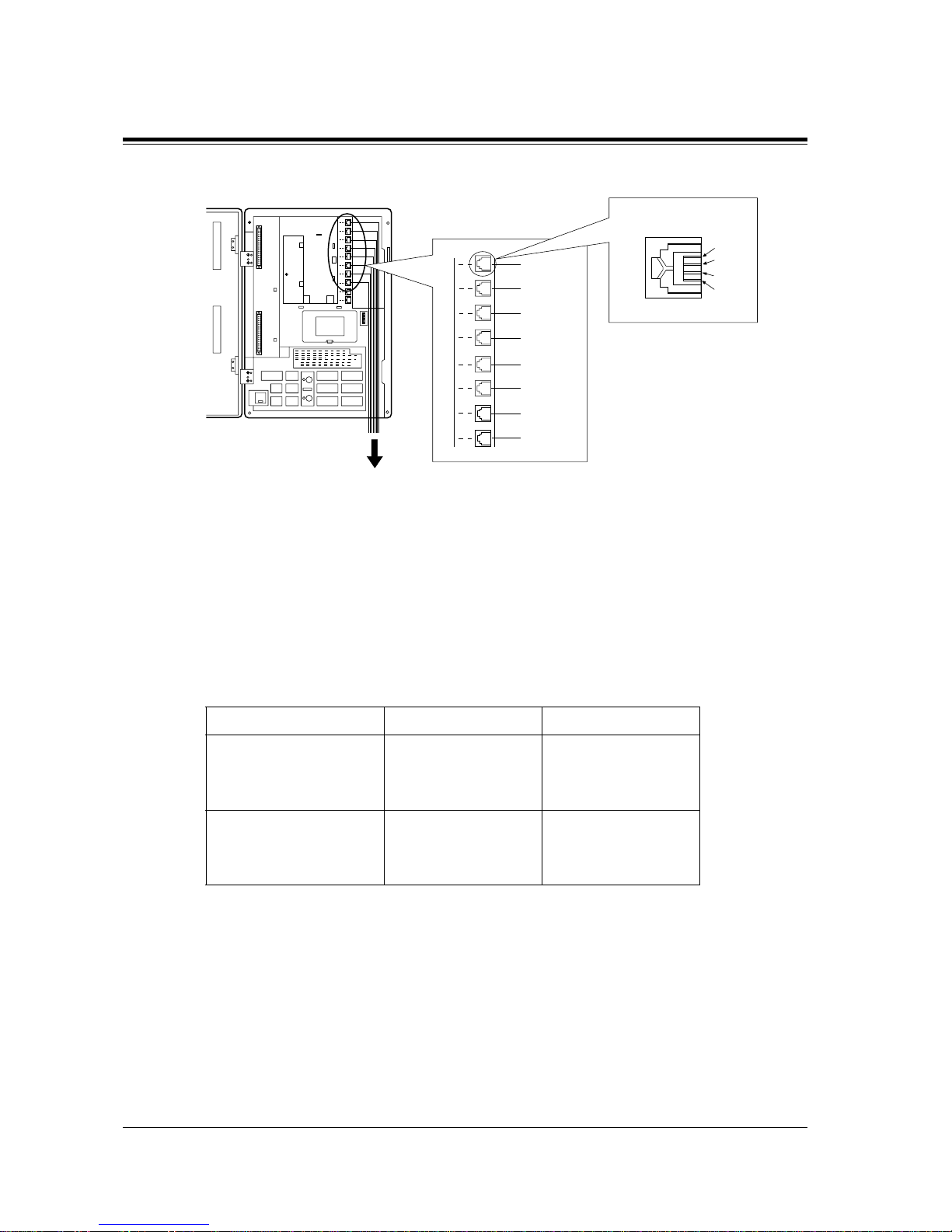
Extension jacks 1 through 16 are for all kinds of telephones.
Maximum Cabling Distance
The maximum length of the e xtension line cord (t wisted cable ) which connects t he system and
the extension is as follows:
Telephone Wiring
2, 4 or 6-conductor wiri ng is requ ired for e ach e xtension a s listed bel o w. There are six pins for
possible connection: "T", "R", "D1", "D2", "P1" and "P2".
T: Tip
R: Ring
D1: Data 1
D2: Data 2
P1: 3 Pair Voice (OHCA)
P2: 3 Pair Voice (OHCA)
Diameter of the line Max. length
Single Line Telephone 22 AWG
24 AWG
26 AWG
1798 m
1128 m
698 m
Proprietary Telephone /
Console
22 AWG
24 AWG
26 AWG
360 m
229 m
140 m
Jack 08
Jack 07
Jack 06
Jack 05
Jack 04
Jack 03
Jack 02
Jack 01
R: Ring T: Tip
D2
R
T
D1
View of TEL Jack (Extension)
D1: Data 1 D2: Data 2
To extensions (Jacks 01 – 08)
Page 47
2.3 Connection
General Installation
47
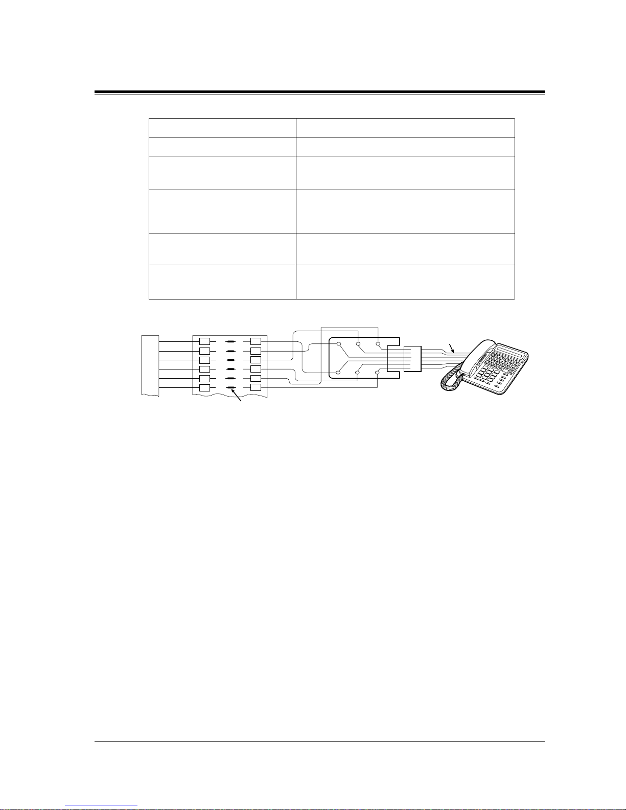
*3-pair twisted cabling
Telephone Wiring
Single Line telephone 1 pair wire (T, R)
Digital proprietary telephone
(e.g. KX-T7536, KX-T7235)
1 pair wire (D1, D2) or
2 pair wire (D1, D2, T, R) for eXtra Device Port
Analogue proprietary telephone
except KX-T7130 (e.g. KXT7020, KX-T7030)
2 pair wire (D1, D2, T, R)
KX-T7130 Analogue proprietary
telephone
3 pair wire* (D1, D2, T, R, P1, P2)
Console
(e.g. KX-T7540, KX-T7240)
1 pair wire (D1, D2)
50-Pin Connector
Block Terminal
1
2
3
4
5
6
26
1
27
2
28
3
6
5
4
3
2
1
Green
Red
Black
Yellow
White
Blue
1
2
3
4
5
6
Line cord
Bridging Clips
Page 48

2.3 Connection
48 General Installation
Connection
1. Insert the 50-pin connector to the Extension Jack as shown.
2. Connect the wire cords to the appr opriate connector p ins and the termina l equipment. Refe r
to the Telephone Wiring (Page 45) and Pin Number Chart (Page 49).
3. After inserting the connector, fasten the connector with the nylon tie.
25
50
1
26
Connector type
50-pin (Amphenol 57JE
series or the equivalent)
To extensions
(Jacks 09-16)
To extensions
(Jacks 01-08)
Page 49

2.3 Connection
General Installation
49
Pin Number Chart
Pin no. EXTN. 01-08 EXTN. 09-16 8EXTN. 8EXTN.
26
1
27
2
28
3
Jack
No.01
T
R
D1
D2
P1
P2
Jack
No.09
T
R
D1
D2
P1
P2
Jack
No.17
T
R
D1
D2
P1
P2
Jack
No.25
T
R
D1
D2
P1
P2
29
4
30
5
31
6
Jack
No.02
T
R
D1
D2
P1
P2
Jack
No.10
T
R
D1
D2
P1
P2
Jack
No.18
T
R
D1
D2
P1
P2
Jack
No.26
T
R
D1
D2
P1
P2
32
7
33
8
34
9
Jack
No.03
T
R
D1
D2
P1
P2
Jack
No.11
T
R
D1
D2
P1
P2
Jack
No.19
T
R
D1
D2
P1
P2
Jack
No.27
T
R
D1
D2
P1
P2
35
10
36
11
37
12
Jack
No.04
T
R
D1
D2
P1
P2
Jack
No.12
T
R
D1
D2
P1
P2
Jack
No.20
T
R
D1
D2
P1
P2
Jack
No.28
T
R
D1
D2
P1
P2
38
13
39
14
40
15
Jack
No.05
T
R
D1
D2
P1
P2
Jack
No.13
T
R
D1
D2
P1
P2
Jack
No.21
T
R
D1
D2
P1
P2
Jack
No.29
T
R
D1
D2
P1
P2
Page 50

2.3 Connection
50 General Installation
Note
• "8EXTN" in the table indicates an extension expansion area for 8-Station Line Unit (KXTD170). System Programming is required for card location identification. <SYS PRG
[109]>
• If a telephone or answering mac hin e wit h an A-A1 re lay is con nec ted to the main uni t, set
the A-A1 relay switch of the te lephone or answering machine to OFF positio n.
• Mis-connection may cause the system to operate improperly. See 6.1.1 Installation and
6.1.2 Connection.
• Up to four consoles (e.g. KX-T7540) can be installed per system. As the console itself
cannot work al one, it alw ays requires a proprietary t elephone used i n pair . Place the console
and the paired telephone side by side on your desk.
• It is necessary to designa te the jack number s of paired con soles and propri etary tel ephones
by System Programming. <SYS PRG [007]>
41
16
42
17
43
18
Jack
No.06
T
R
D1
D2
P1
P2
Jack
No.14
T
R
D1
D2
P1
P2
Jack
No.22
T
R
D1
D2
P1
P2
Jack
No.30
T
R
D1
D2
P1
P2
44
19
45
20
46
21
Jack
No.07
T
R
D1
D2
P1
P2
Jack
No.15
T
R
D1
D2
P1
P2
Jack
No.23
T
R
D1
D2
P1
P2
Jack
No.31
T
R
D1
D2
P1
P2
47
22
48
23
49
24
Jack
No.08
T
R
D1
D2
P1
P2
Jack
No.16
T
R
D1
D2
P1
P2
Jack
No.24
T
R
D1
D2
P1
P2
Jack
No.32
T
R
D1
D2
P1
P2
50
25
Pin no. EXTN. 01-08 EXTN. 09-16 8EXTN. 8EXTN.
Page 51
2.3 Connection
General Installation
51
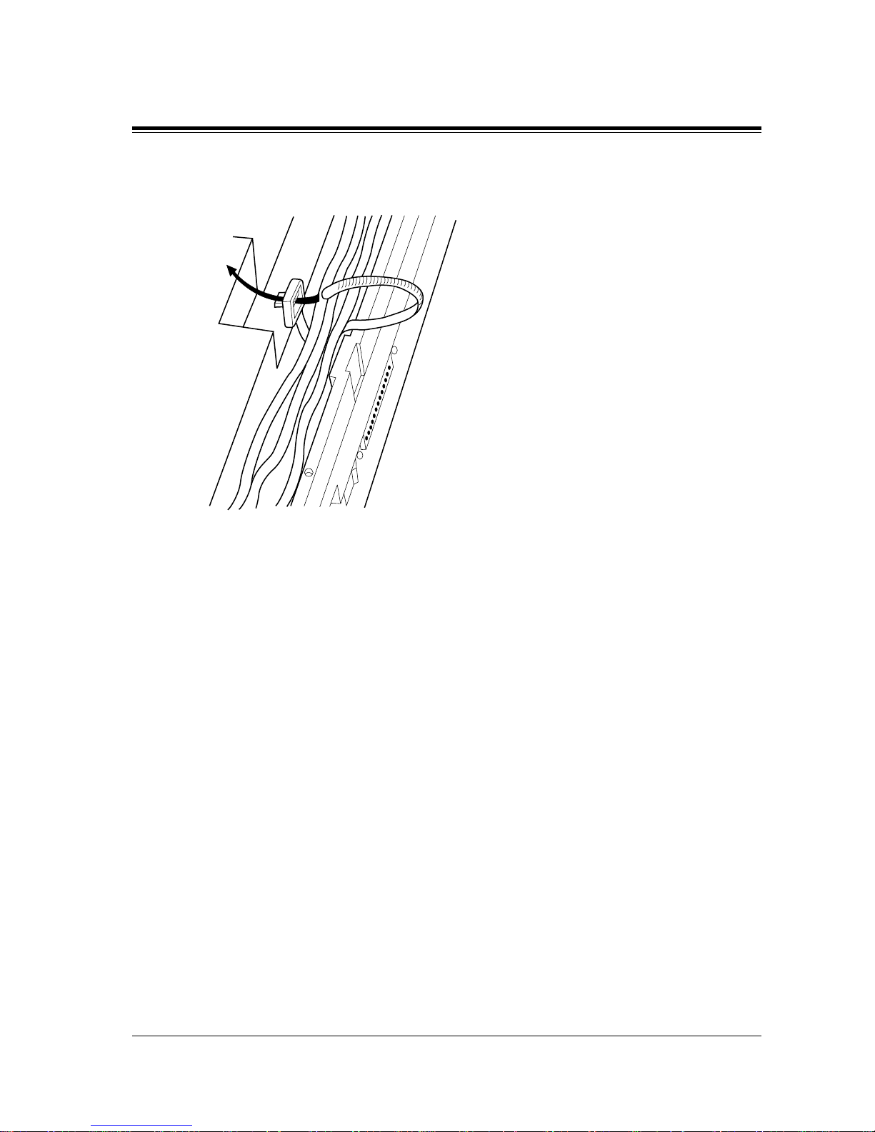
• After completing all the required inside cabling, including outside lines, extensions,
external pagers and external music sources, fasten the cables with the nylon tie (included)
as shown.
Programming Guide References
[007] Console Port and Paired Telephone Assignment
[109] Expansion Unit Type
Features Guide References
Console
Page 52
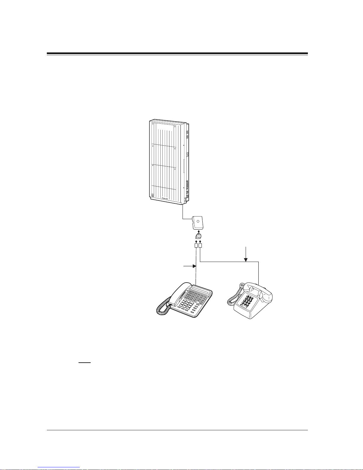
2.3 Connection
52 General Installation
2.3.3 Parallelled Telephone Connection
Any single line tele phone can be connec ted in parall el with a proprie tary tele phone as follo ws:
Method 1: Using a Modular T-Adaptor
Note
• The KX-TD1 232 is illustrated as the main u nit.
• The 6-con ductor wiring cord (and the Modular T-Adaptor KX-J36) is required if the
proprietary telephone KX-T7130 is to be used for parallel connection for KX-TD1232.
D1232
DIGITAL SUPER HYBRID SYSTEM
Single Line TelephoneDigital / Analogue
Proprietary Telephone
2-conductor wiring cord
Connect pins
“T” and “R”.
4-conductor wiring cord
For DPT: Connect pins
“D1” and “D2”
only. (
“T” and “R” are not necessary.)
For APT: Connect pins
“T”, “R”, “D1”
and
“D2”.
Modular T-Adaptor
(Panasonic KX-J66 or USOC RJA2X)
Page 53
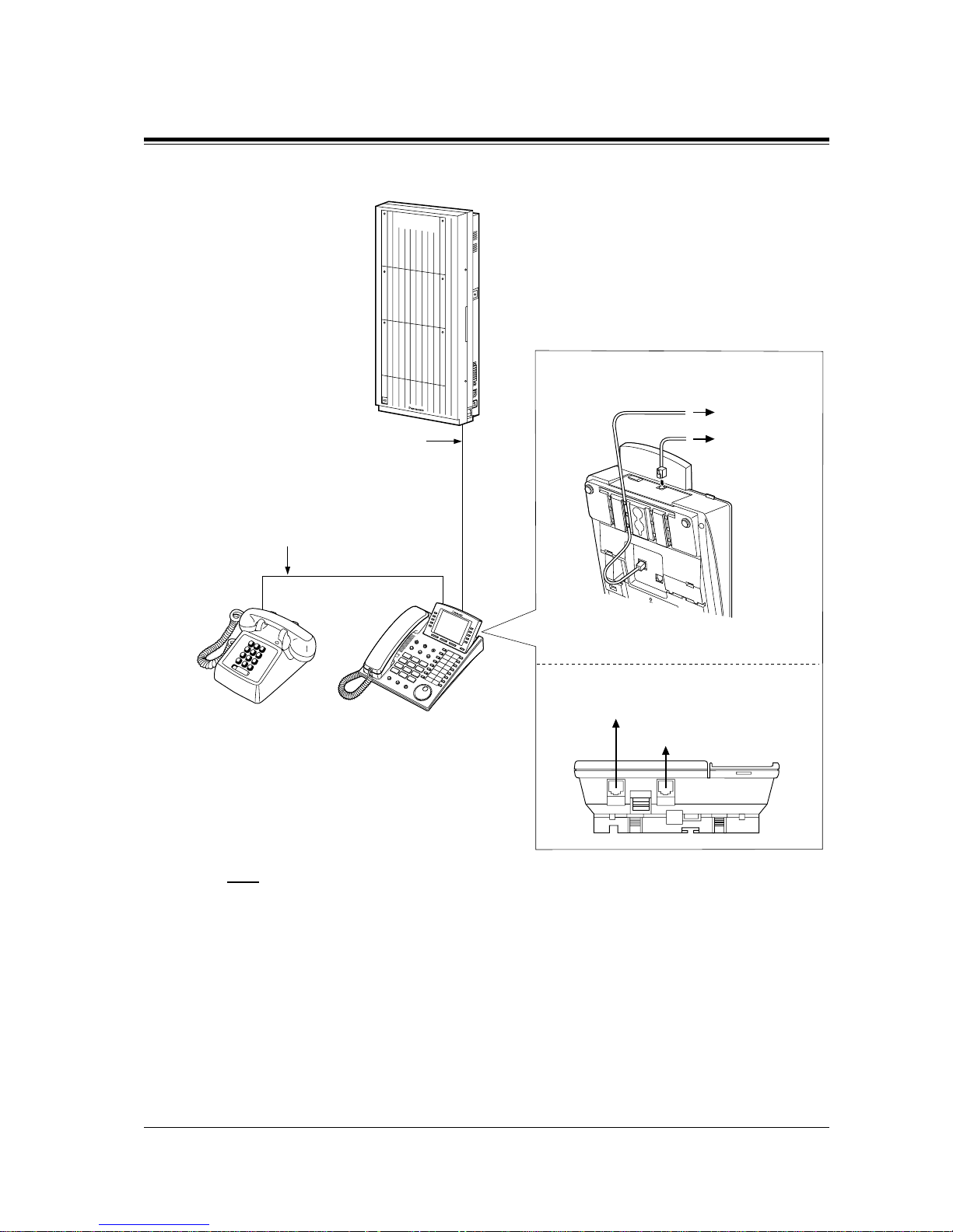
2.3 Connection
General Installation
53
Method 2: For Digital Proprietary Telephones only
Note
• The KX-TD1232 is illustrated as the main unit.
• Not only a single line telephone but a single line device such as an answering machine, a
facsimile or a modem (personal computer) etc. can be connected in parallel with a
proprietary telephone.
Features Guide References
Parallelled Telephone
To system
To single line
telephone
Single Line Telephone Digital Proprietary
Telephone
2-conductor wiring cord
Connect pins
“T” and “R”.
4-conductor wiring cord
Connect pins
“T”, “R”,
“D1” and “D2”.
<Back of the KX-T7500/KX-T7400
Series DPTs>
<Back of the KX-T7200 Series DPTs>
To system
To single line telephone
TO TEL
TO EMSS
LCD ADJ
PUSH
D1232
DIGITAL SUPER HYBRID SYSTEM
Note: The above illustration is
the KX-T7500.
Page 54
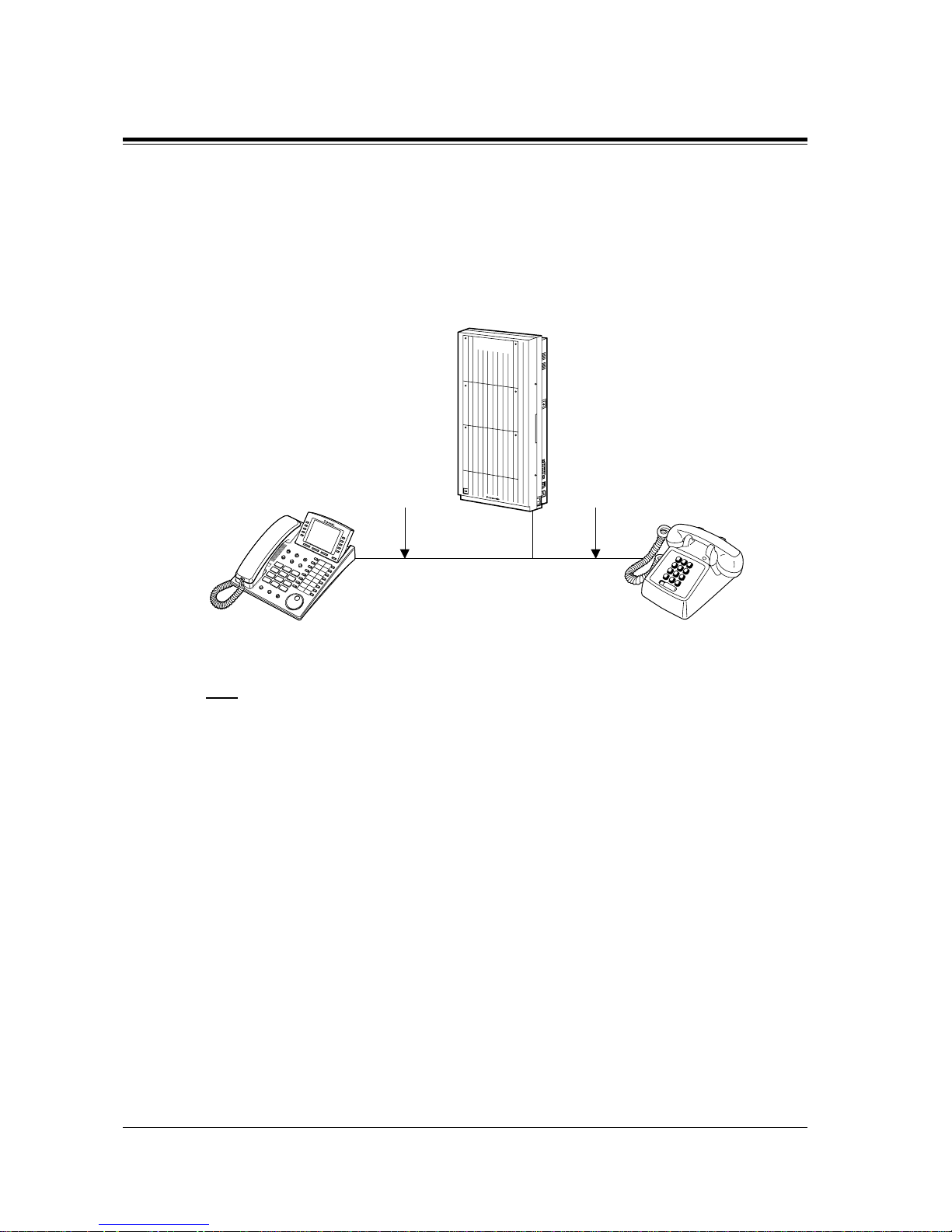
2.3 Connection
54 General Installation
2.3.4 EXtra Device Port (XDP) Connection
A digital proprietary telephone and a single Line telephone can be connected to the same
extension jack yet have different extension numbers (eXtra Device Port feature). System
Programming is required for this jack.
Method 1
Note
• The KX-TD1 232 is illustrated as the main u nit.
Method 2
Section 2.3.3 Parallelled Telephone Connection, Method 2: for Digital Proprietary
Telephone only is also available for XDP connection.
Programming Guide References
[600] EXtra Device Port
Features Guide References
EXtra Device Port (XDP)
D1232
DIGITAL SUPER HYBRID SYSTEM
Single Line TelephoneDigital Proprietary
Telephone
2-conductor wiring cord
Connect pins “T” and “R”.
4-conductor wiring cord
Connect pins “D1” and “D2”.
(“T” and “R” are not necessary.)
Page 55
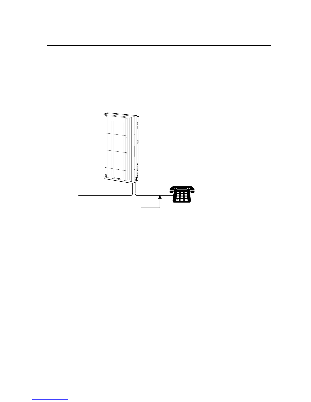
2.3 Connection
General Installation
55
2.3.5 Polarity Sensitive Telephone Connection
If your telephone is polarity sensitive, follow the procedure below:
1. Complete all the required extension wiring.
2. Confirm that dialling can be done from all the extensions using a touch-tone telephone. If
dialling fails, the polarity between the extension and the system must be reversed.
3. Reverse as shown.
4. Set the Power Switch to "OFF" position.
5. Connect all outside lines.
6. Confirm that dialling can be done on the following extensions using a tone telephone.
KX-TD816
Extension (T, R) of jack 01: Outside line 01
Extension (T, R) of jack 02: Outside line 02
Extension (T, R) of jack 09 and 10 (Extension Expansion Card): Outside line 5 and 6
KX-TD1232
Extension (T, R) of jack 01: Outside line 01
Extension (T, R) of jack 02: Outside line 02
Extension (T, R) of jack 09: Outside line 03
Extension (T, R) of jack 10: Outside line 04
Extensions (T, R) of jacks 17 and 18 (Extension Expansion Card 1): Outside line 09 and 10
(Note: Extensions of jacks 09 and 10 for KX-TD816, and 17 and 18 for KX-TD1232
depend on the Power Failure Transfer connection. For details, refer to Section
2.5.1 Auxiliary Connection for Power Failure Transfer.)
If dialling fails, the polarity between the system and the outside line must be reversed.
D1232
DIGITAL SUPER HYBRID SYSTEM
1
2
3
4
5
6
7
8
9
0
#
Central Office Line
Reverse here.
Extension
Page 56
2.3 Connection
56 General Installation
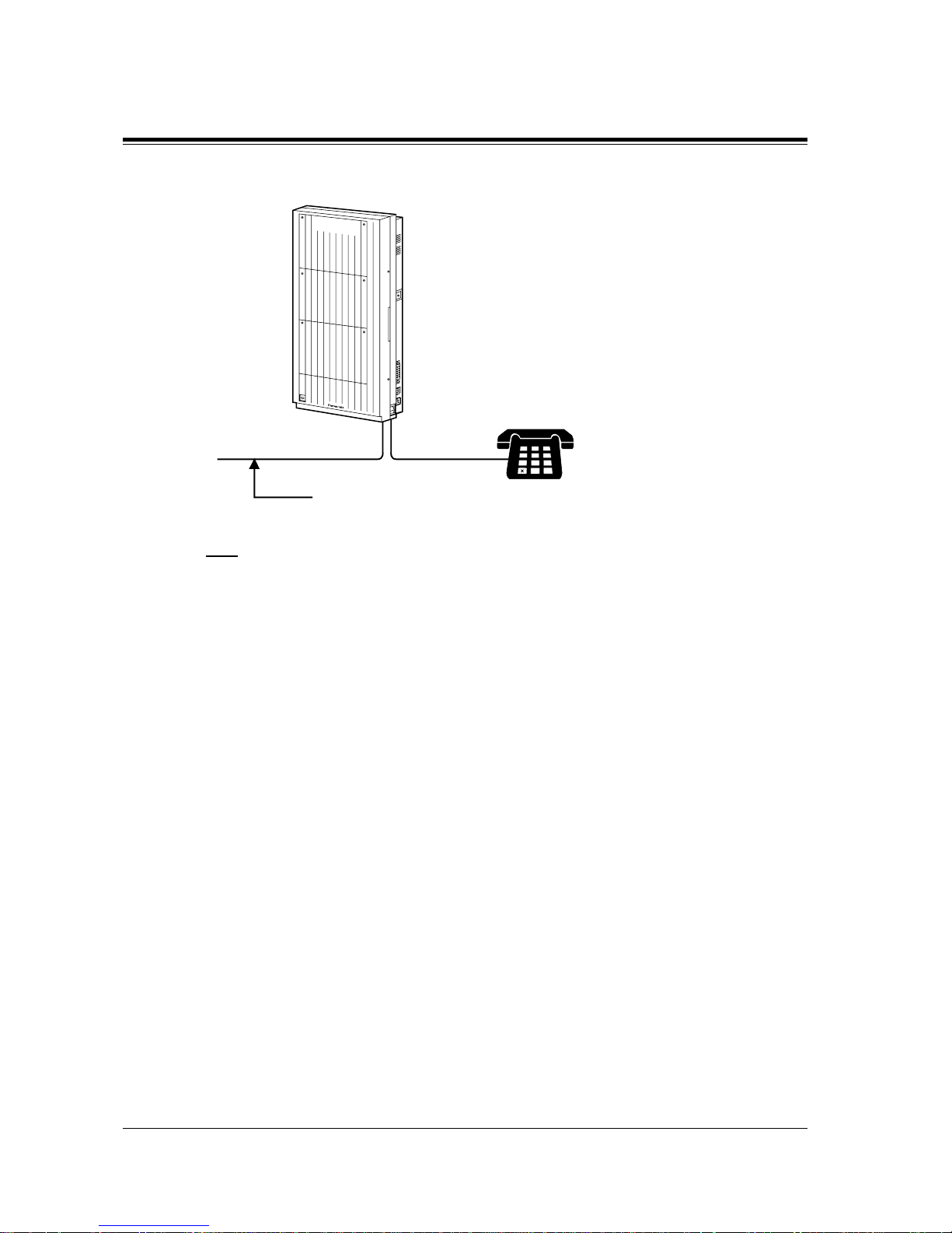
7. Reverse as shown.
8. Every time an extension telephone is replaced, repeat the above procedure.
Note
The KX-TD1232 is illustrated as the main unit.
D1232
DIGITAL SUPER HYBRID SYSTEM
1
2
3
4
5
6
7
8
9
0
#
Central Office Line
Reverse here.
Extension
Page 57
2.3 Connection
General Installation
57
2.3.6 External Pager (Paging Equipment) Connection
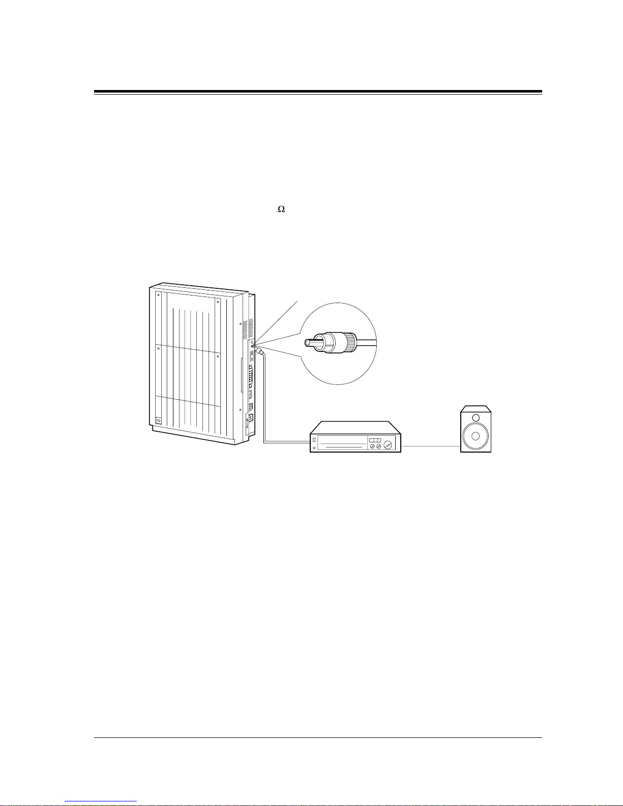
KX-TD816
One external pager (user-supplied) can be connected to the KX-TD816 as illustrated below.
Use an RCA connector and shielded cable.
• Output impedance: 600
Maximum length of the cable
AWG 18 – 22: Under 10 m
Panasonic
D816
DIGITAL SUPER HYBRID SYSTEM
Paging Equipment
Paging jack
Amplifier
Speaker
Page 58
2.3 Connection
58 General Installation
KX-TD1232
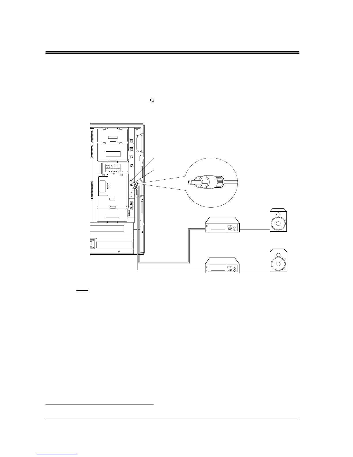
Up to two external pagers (user-supplied) can be connected to the KX-TD1232 per system as
illustrated b elow.
Use an RCA connector and shielded cable.
• Output impedance: 600
Maximum length of the cable
AWG 18 – 22: Under 10 m
Note
• System Connection*1 permits a maximum of four external pagers.
It is programmable which external pager will send background music and whether all the
pagers will generate a confirmation tone.
• To adjust the sound level of the pagers, use the volume control on the amplifiers.
Programming Guide References
[804] External Pager BGM
[805] External Pager Confirmation Tone
*1
Available for the KX-TD1232 only.
REMOTE
SYSTEM INTER
CONNECTION
DISA
DOORPHONE
Paging Jack 2
Paging Jack 1
Amplifier
Paging Equipment 2
Amplifier
Paging Equipment 1
Speaker
Speaker
Page 59

2.3 Connection
General Installation
59
Features Guide References
Background Music (BGM)
Paging
Trunk (Outside Line) Answer From Any Station (TAFAS)
Page 60
2.3 Connection
60 General Installation
2.3.7 External Music Source Connection
KX-TD816
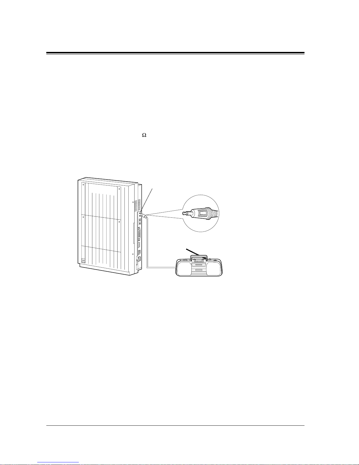
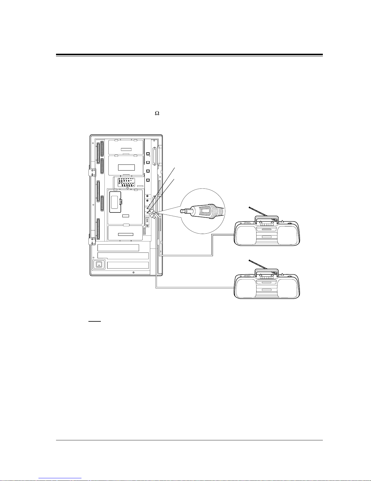
One music source such as a radio (user-supplied) can be connected to the KX-TD816 as
illustrated b elow.
Insert the plug to the earphone / headphone jack on the external music source. Use a twoconductor plug (3.5 mm in diameter).
• Input impedance: 8
Maximum length of the cable
AWG 18 – 22: Under 10 m
External Music Source
Panasonic
D816
DIGITAL SUPER HYBRID SYSTEM
External Music Jack
Page 61
2.3 Connection
General Installation
61
KX-TD1232
Up to two music sources such as a radio (user-s uppl ied) can be connected to the KX-TD1232
per system as illustrated below.
Insert the plug to the earphone / headphone jack on the external music source.
Use a two-conductor plug (3.5 mm in diameter).
• Input impedance: 8
Maximum length of the cable
AWG 18 – 22: Under 10 m
Note
• By default setting, Music Source 1 is used for Music on Hold and Background Music
(BGM). <SYS PRG [803]>
• The system is provided with an inter nal music sour ce. By defa ult sett ing, an in ternal music
source is used as Music Source 1. System Prog ramming is required to use an e xternal music
source or tone as Music Source 1. <SYS PRG [990], Area 06-Bits 11 and 10>
• T o adjust the sou nd level of th e Music on Hold, use the v olume control on the e xternal music
source.
Programming Guide References
[803] Music Source Use
[990] System Additional Information
REMOTE
SYSTEM INTER
CONNECTION
DISA
DOORPHONE
External Music Jack 2
External Music Jack 1
External Music Source 2
External Music Source 1
Page 62

2.3 Connection
62 General Installation
Features Guide References
Background Music (BGM)
Page 63
2.3 Connection
General Installation
63
2.3.8 Printer and PC Connection
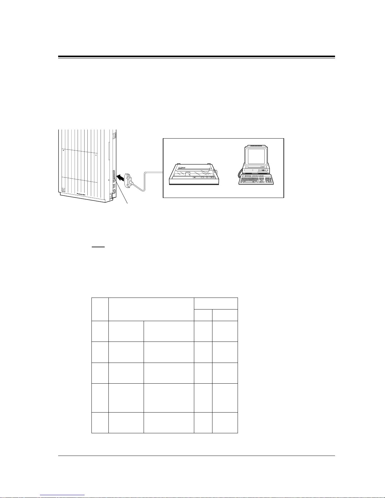
A user-supplied printer or personal computer (PC) can be connected to the system. These are
used to print out or refer to the Station Message Detail Recording (SMDR) call records and
system programming data.
Connect the printer cable or the PC cable to the Serial Interface (RS-232C) connector. The
cable must be shielded and the maximum length is 2 m.
Note
The KX-TD123 2 is illustrated as the main uni t.
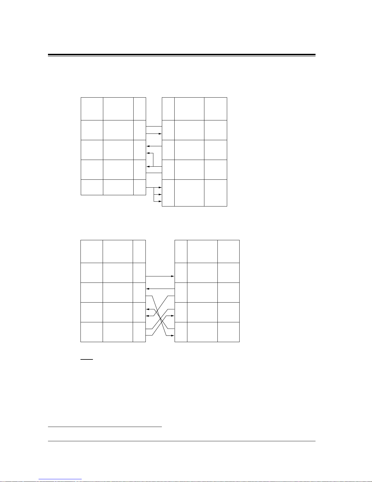
Arrange cables so that t he prin ter wil l be conn ected t o the sys tem as sh o wn i n the cha rt on th e
following page.
The pin configuration of Serial Interface (RS-232C) Connector is as follows:
Pin
No.
Signal Name Circuit Type
EIA CCITT
12FG
SD (TXD)
Frame Ground
Transmitted DataAABA
101
103
34RD (RXD)
RS (R TS)
Received Data
Request To SendBBCA
104
105
56CS (CTS)
DR (DSR)
Clear To Send
Data Set Ready
CB
CC
106
107
78SG
CD (DCD)
Signal Ground
Data Carrier
Detect
ABCF102
109
20 ER (DTR) Data Terminal
Ready
CD 108.2
Serial Interface
(RS-232C) (25-pin)
Printer or Computer
Page 64
2.3 Connection
64 General Installation
Connection Chart for Printer / IBM*1 Personal Computer
If you connect a printer or a PC with a 25-pin cable, follow the chart below.
If you connect a printer or an IBM-PC with a 9-pin cable, follow the chart below.
Note
Please read your printer manual and connect the first EIA pin (FG) of this unit to the printer
cable.
*1
IBM is registered trademark of International Business Machines Corporation.
Circuit
Type
(EIA)
Signal
Name
Pin
No.
AA
BAFGSD (TXD)
RD (RXD)
CS (CTS)
DR (DSR)
SG
ER (DTR)
Signal
Name
FG
RD (RXD)
SD (TXD)
ER (DTR)
SG
CS (CTS)
DR (DSR)
CD (DCD)
1
2
3
5
6
7
20
Pin
No.
1
3
2
20
7
5
6
8
BB
CB
CC
AB
CD
Circuit
Type
(EIA)
AA
BB
BA
CD
AB
CB
CC
CF
System 25-pin Cable Printer/PC
Circuit
Type
(EIA)
Signal
Name
Pin
No.
AA
BAFGSD (TXD)
RD (RXD)
RS (RTS)
CS (CTS)
DR (DSR)
1
2
3
4
5
6
BB
CA
CB
CC
SG
ER (DTR)720
AB
CC
Circuit
Type
(EIA)
Signal
Name
Pin
No.
BBRD (RXD)
SD (TXD)
ER (DTR)
SG
DR (DSR)
2
3
4
5
6
BA
CD
AB
CC
RS (RTS)
CS (CTS)
7
8
CA
CB
System
9-pin Cable Printer/IBM-PC
Page 65

2.3 Connection
General Installation
65
Serial Interface (RS-232C) Signals
Frame Ground: FG
Connects to the unit frame and the earth ground conductor of the AC power cord.
Transmitted Data: SD (TXD): (output)
Conv eys signa ls from the unit to the pr inter . A "Mark" con dition is held unl ess data or BREAK
signals are being transmitted.
Received Data: RD (RXD): (input)
Conveys signals from the printer.
Request to Send: RS (RTS): (output)
This lead is held ON whenever DR (DSR) is ON.
Clear To Send: CS (CTS): (input)
An ON condition of circuit CS (CTS) indicates that the printer is ready to receive data from the
unit. The unit does not attempt to transfer data or receive data when circuit CS (CTS) is OFF.
Data Set Ready: DR (DSR): (input)
An ON condition of circuit DR (DSR) i ndicates the printer is rea dy . Circuit DR (DSR) ON does
not indicate that communication has been established with the printer.
Signal Ground: SG
Connects to the DC ground of the unit for all interface signal.
Data Terminal Ready: ER (DTR): (output)
This signal line is turned ON by the unit to indicate that it is ON LINE. Circuit ER (DTR) ON
does not indicate t hat communi cation ha s been es tablishe d with the printe r. It is switched OFF
when the unit is OFF LINE.
Data Carrier Detect: CD (DCD): (input)
The ON condition is an indication to data terminal (DTE) that the carrier si gnal is being
received.
Programming Guide References
[800] SMDR Incoming / Outgoing Call Log Printout
[801] SMDR Format
[802] System Data Printout
[806-807] Serial Interface (RS-232C) Parameters
[990] System Additional Information
Features Guide References
Hotel Applica tion
Station Message Detail Recording (SMDR)
System Programming and Diagnosis with Personal Computer
Page 66
2.3 Connection
66 General Installation
2.3.9 Installation of Lightning Protectors
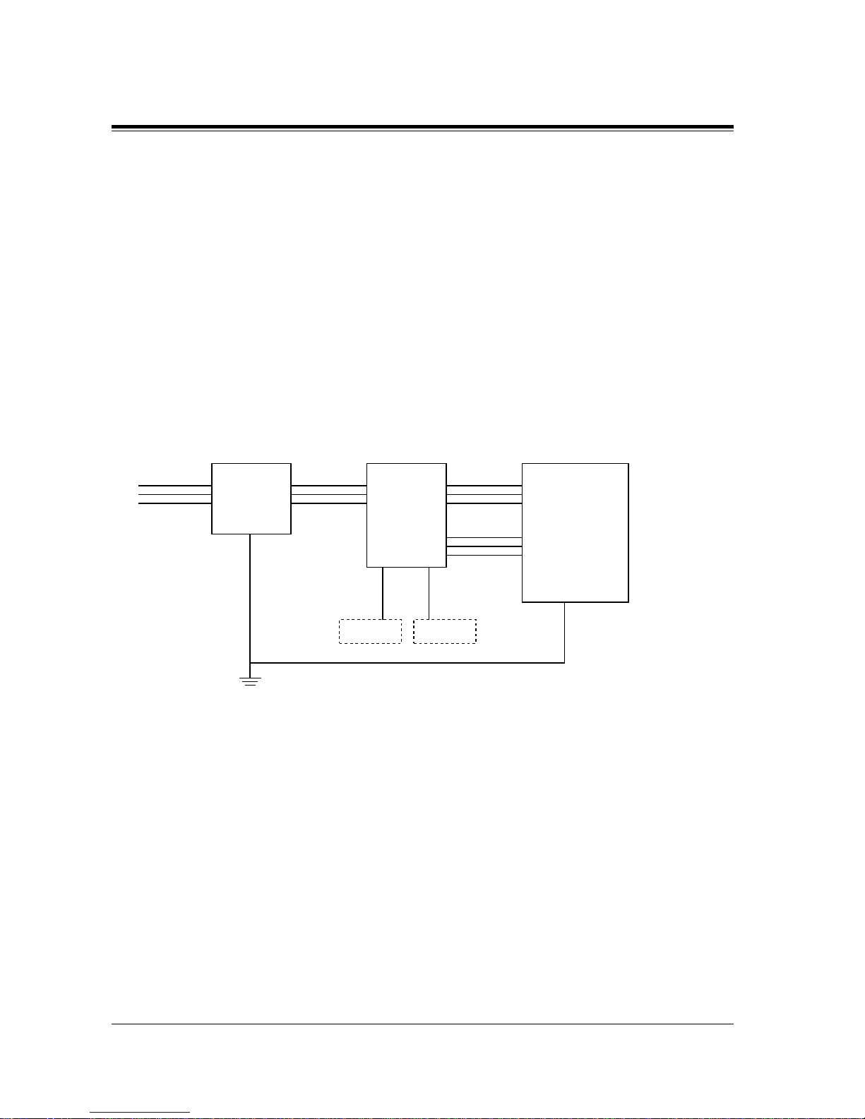
Overview
A lightning protect or is a de vi ce to be install ed on an out side li ne to pre v ent a d angerous s urge
from entering the building and damaging equipment.
A dangerous surge can occur if a telephone line comes in contact with a power line. Trouble
due to lightning sur ges has been sho wi ng a steady in crease with t he de v elopment of electr onic
equipment.
In many countries, there are regulations requiring the installation of a lightning protector. A
lightning strike to a telephone cable which is 10 m above ground can be as high as 200,000 V.
This system should be instal led wit h light ning prot ector s. In addi tion, groundin g (co nnection
to earth ground) is very important for the protection of the system.
Installation Diagram
TEL
Lightning
Protectors
CO
Terminal
Board
CO
System
Ground
Terminal
CO
EXTN
EXTN
Ground
EXTN
TEL
Frame Ground
CO: Central Office (Outside line)
EXTN: Extension line
TEL: Telephone
Page 67
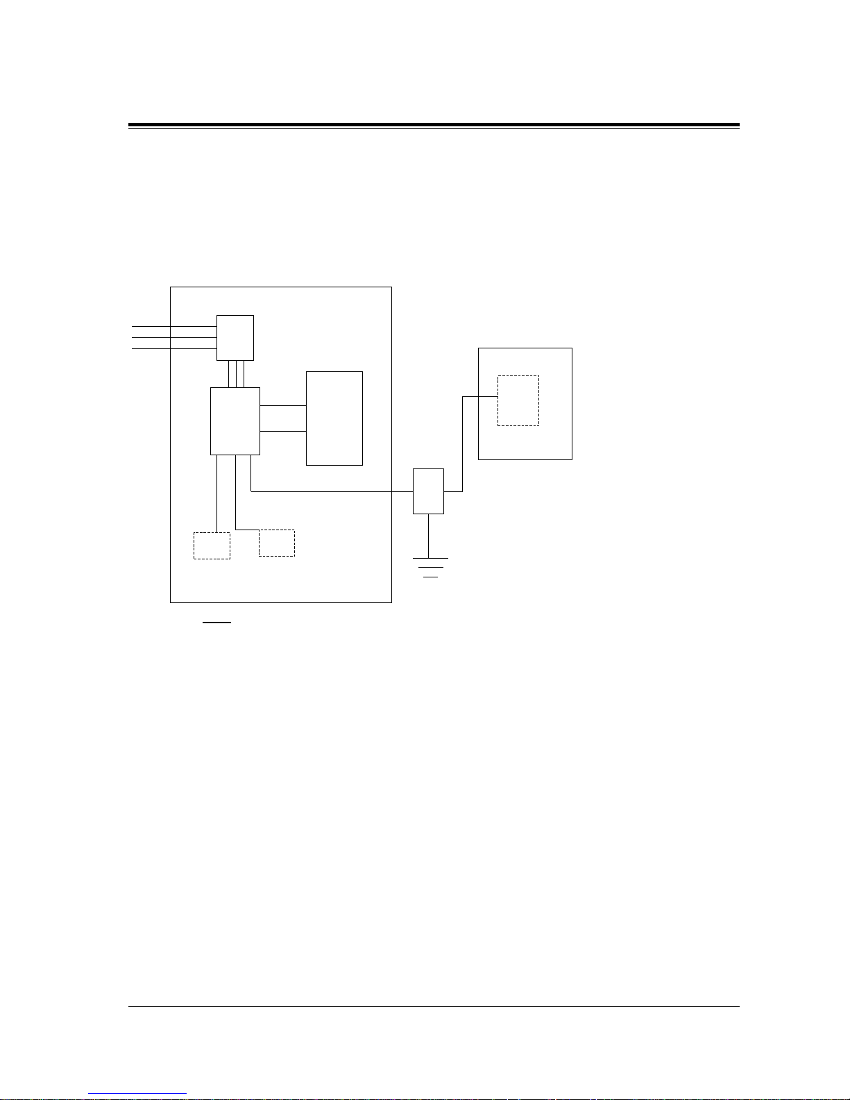
2.3 Connection
General Installation
67
Outside Installation Diagram
If you install an extension outside of the main building, the following precautions are
recommended:
a) Install the extension wire underground.
b) Use a conduit to protect the wire.
Note
The lighting protector for an extension is different from that for outside line.
(Main Building)
CO
(Another Building)
CO
CO
Ter-
minal
Board
Main
Unit
Protectors
EXTN
TELTEL
EXTN
SLT
PT
EXTN
Lightning
Protector
EXTN
Ground
Page 68
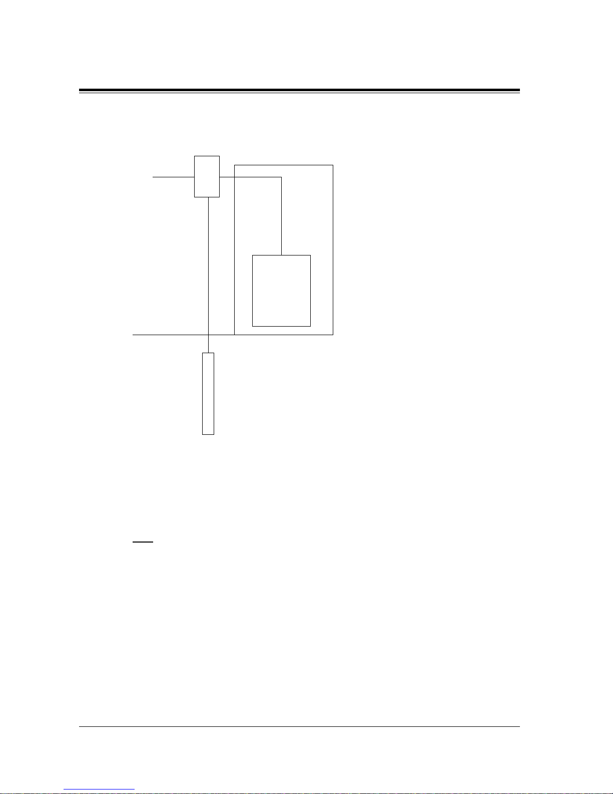
2.3 Connection
68 General Installation
Earth Rod Installation Diagram
1. Installation location of the earth rod: Near the protector
2. Check obstructions: None
3. Composition of the earth rod: Metal
4. Depth of the earth rod: More than 50 cm
5. Size of the grounding wire: Thickness is more than 16 AWG
Note
• The above figures are recommendations only.
• The length of earth rod and the required depth depend on the composition of the soil.
Lightning
Protector
CO
Main
Unit
(Main Building)
Grounding
Wire
(Underground)
Earth Rod
Page 69
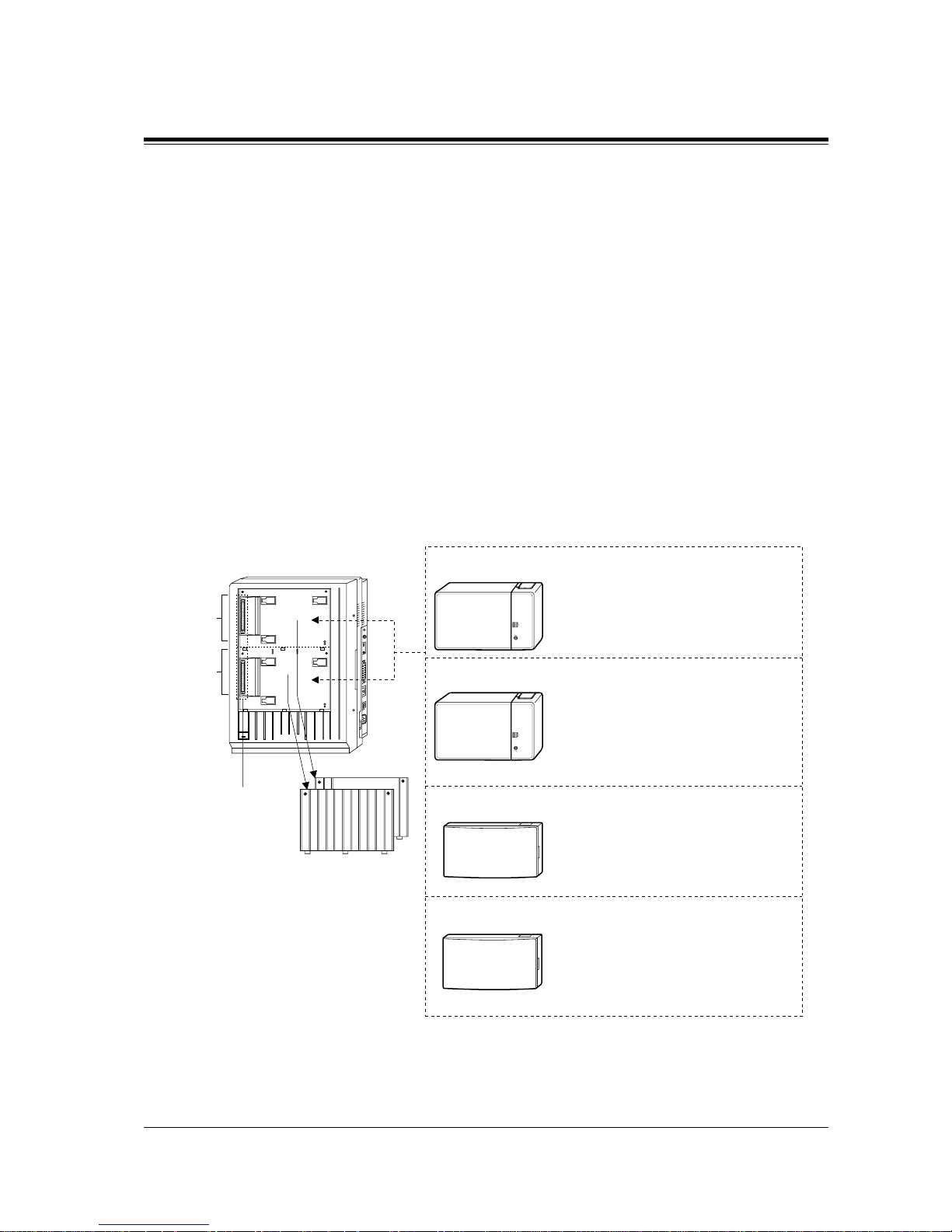
2.4 Installation of Optional Cards and Unit
General Installation
69
2.4 Installation of Optional Cards and Unit
2.4.1 Location of Optional Cards and Units
The location of the optional cards and units is shown below.
Precaution
T o pr otect the printed c ircuit board s (P-boards ) from stati c electri city, do not touch parts on the
P-boards in the main unit and on the optional cards.
Expansion Units
KX-TD816
The following expansion units can be installed to any of the two expansion areas.
Panasonic
D816
Expansion
area 2
Expansion
area 1
Expansion Unit
Connectors
Remove the front
cover plate(s).
8-Station Line Unit, KX-TD170
or
16 SLT Line Circuit Unit, KX-TD174
4-CO Line Unit, KX-TD180
One extension line unit
One outside line unit
A High Speed Remote Card (KXTD197) can be installed into this unit.
One DISA Unit, KX-TD190
A DISA Card (KX-TD199) can be
installed into this unit.
One Remote Unit, KX-TD198
Page 70
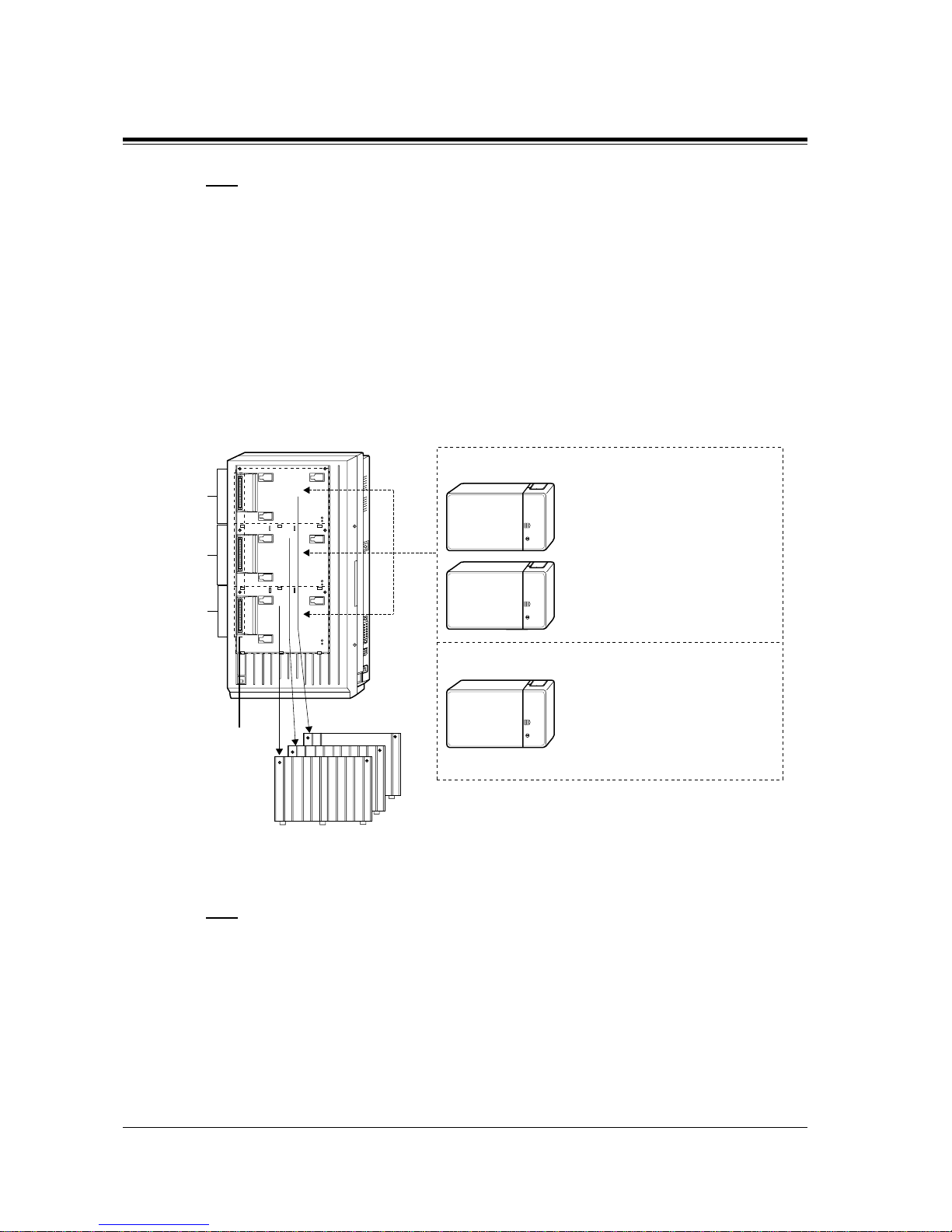
2.4 Installation of Optional Cards and Unit
70 General Installation
Note
• System Programming is required for expansion unit location. <SYS PRG [109]>
Default:
Area 1 = 4-CO Line Unit,
Area 2 = 8-Station Line Unit.
• It is also possible to attach the line expansion unit to the DISA or Remote Unit and install
them to the main unit.
• For unit combinations, refer to Section 1.4.2 Expansion Unit Combination.
KX-TD1232
The following expansion units can be installed to any of the three expansion areas.
Note
• System Programming is required for expansion unit location. <SYS PRG [109]>
Default:
Area 1 = 4-CO Line Unit,
Area 2 and 3 = 8-Station Line Unit.
• It is also possible to attach the line expansion unit to the DISA or Remote Unit and install
them to the main unit.
• For unit combinations, refer to Section 1.4.2 Expansion Unit Combination.
Expansion
area 2
Expansion
area 3
Expansion
area 1
Expansion Unit
Connectors
Remove the cover
plate(s) on the
front cover.
8-Station Line Unit, KX-TD170
or
16 SLT Line Circuit Unit,
KX-TD174
4-CO Line Unit, KX-TD180
Max. two extension line units
One outside line unit
Panasonic
D1232
Page 71
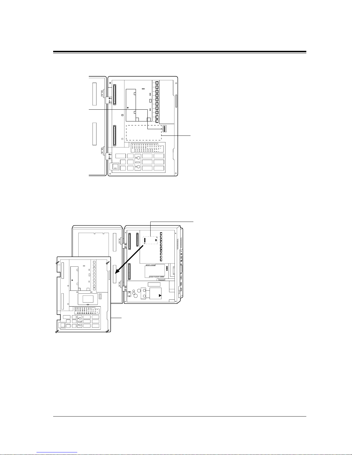
2.4 Installation of Optional Cards and Unit
General Installation
71
Doorphone Card for KX-TD816
Pay Tone Card for KX-TD816
Install Doorphone Card, KX-TD160.
This card connects two doorphones and two
door openers.
Doorphone
Card
Connector
Front Cover
is open.
Install Pay Tone Card, KX-TD189.
This card supports the Pay Tone
service of the central office.
Under this board
Page 72
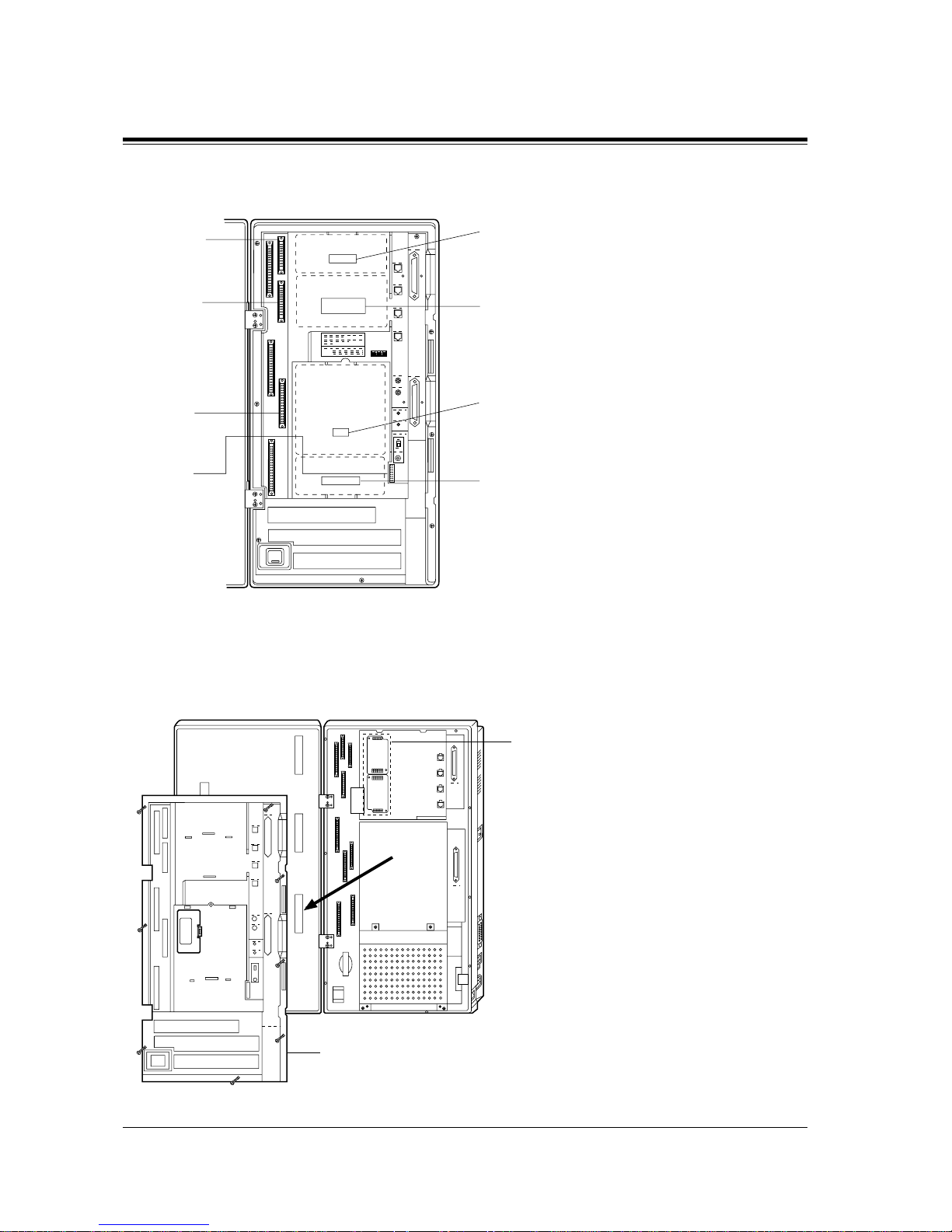
2.4 Installation of Optional Cards and Unit
72 General Installation
Remote Card, System Inter Connection Card, DISA Card, Doorphone Card for KXTD1232
Pay Tone Card for KX-TD1232
Remote Card
Connector
System Inter
Connection
Card
Connector
DISA Card
Connector
Doorphone
Card
Connector
Front Cover is
open.
Install Remote Card, KX-TD196, or
High Speed Remote Card, KX-TD197.
This card provides data communications
between the system and a remote location.
Install System Inter Connection Card,
KX-TD192.
This card connects two systems.
Install DISA Card, KX-TD191.
This card permits access to the system from
outside tone telephones.
Install Doorphone Card, KX-TD160.
This card connects two doorphones and two
door openers.
Install Pay Tone Card, KX-TD189.
This card supports the Pay Tone
service of the central office.
Under this board
Page 73
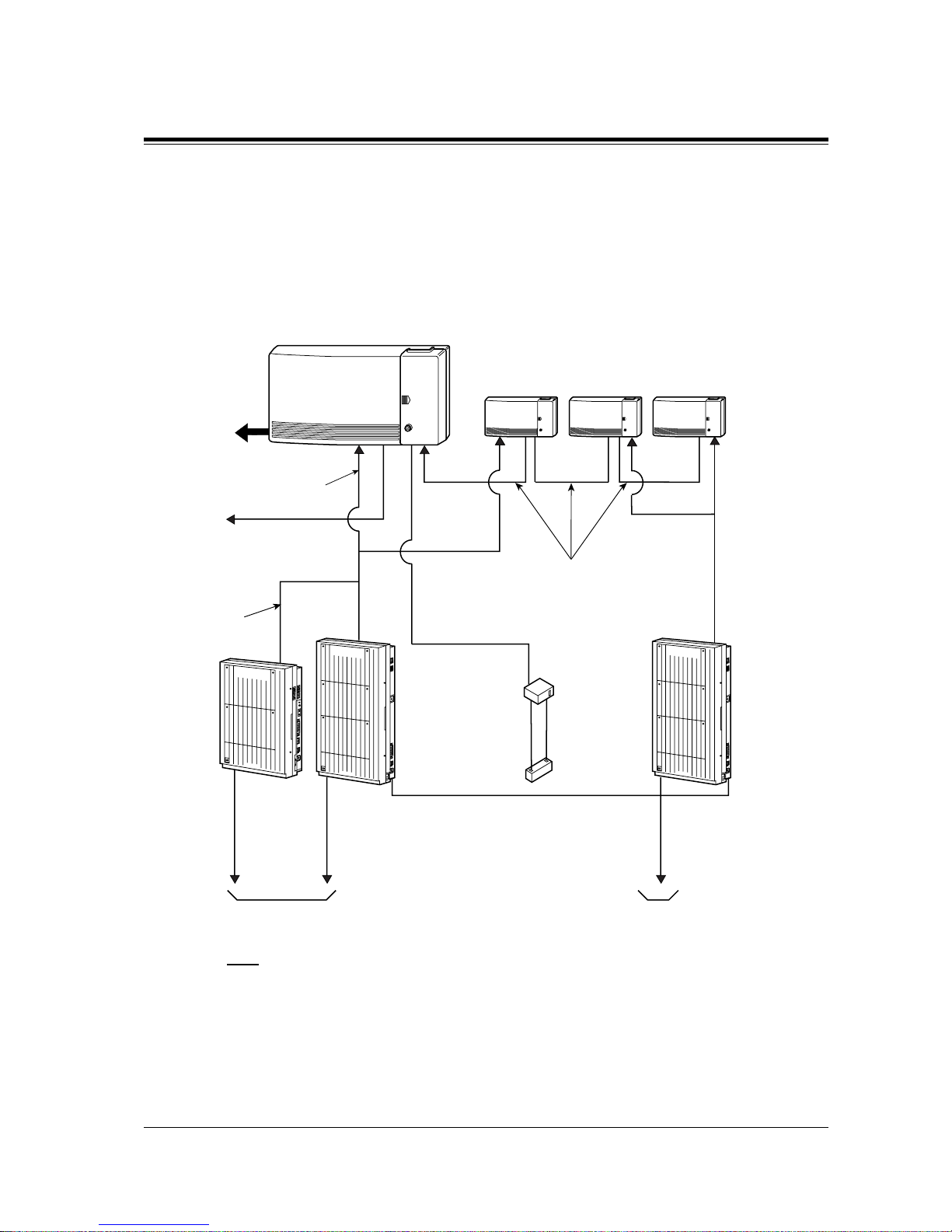
2.4 Installation of Optional Cards and Unit
General Installation
73
SLT Message Waiting Lamp Adaptor Unit
One SLT Message Waiting Lamp Adaptor Unit (KX-TD194) for KX-TD816, and up to three
SLT Message Waiting Lamp Adaptor Units for KX-TD1232 can be installed. This card
supports the Message Waiting feature for a single line te lephone with a messa ge waiting l amp.
One adaptor supports 16 extensions.
Connection Example
Note
Do not connect more than four units with DC connection cables.
Panasonic
D816
DIGITAL SUPER HYBRID SYSTEM
D1232
DIGITAL SUPER HYBRID SYSTEM
Panasonic
D1232
DIGITAL SUPER HYBRID SYSTEM
Panasonic
KX-TD194
KX-TD194 KX-TD194 KX-TD194
To AC outlet
From a KX-TD1232
or KX-TD816
Notice
To stations
16 Extensions
KX-TD816
To AC outlet
To AC outlet
KX-TD1232 System Connection KX-TD1232
(
16-T/R, 1-H/L
)
DC connection cables
To KX-A46
KX-A46
Car battery
<
If each unit is connected to an AC outlet,
these cables are not nessesary.>
Page 74

2.4 Installation of Optional Cards and Unit
74 General Installation
2.4.2 4-CO Line Unit Connection
To add four outside lines (outside lines 05 through 08 for KX-TD816, and outside lines 09
through 12 for KX-TD1232), use the optional 4-CO Line Unit (KX-TD180).
This unit can be installed to any of the expansion unit areas provided on the front of the main
unit. For outsi de line e xpansion un it instal lation, see Section 2.4.5 Installing Expansion Unit.
System Progr amming is required for card lo cation identificat ion.
Programming Guide References
[109] Expansion Unit Type
Page 75

2.4 Installation of Optional Cards and Unit
General Installation
75
2.4.3 8-Station Line Unit Connection
To add eight extensions (jack numbers 09 through 16 for KX-TD816, and jack numbers 17
through 24 or 25 through 32 for KX-TD1232), use the optional 8-Station Line Unit (KXTD170). To add 16 extensions for KX-TD1232 (jack numbers 17 through 32), use two 8Station Line Units.
This unit can be installed to any of the expansion unit areas provided on the front of the main
unit. For extension expansion unit installation, see Section 2.4.5 Installing Expansion Unit.
System Programming is required for card location identification.
This unit can be installed to any of the expansion unit areas provided on the front of the main
unit. For extension expansion unit installation, see Section 2.4.5 Installing Expansion Unit.
System Programming is required for card location identification.
Programming Guide References
[109] Expansion Unit Type
Page 76
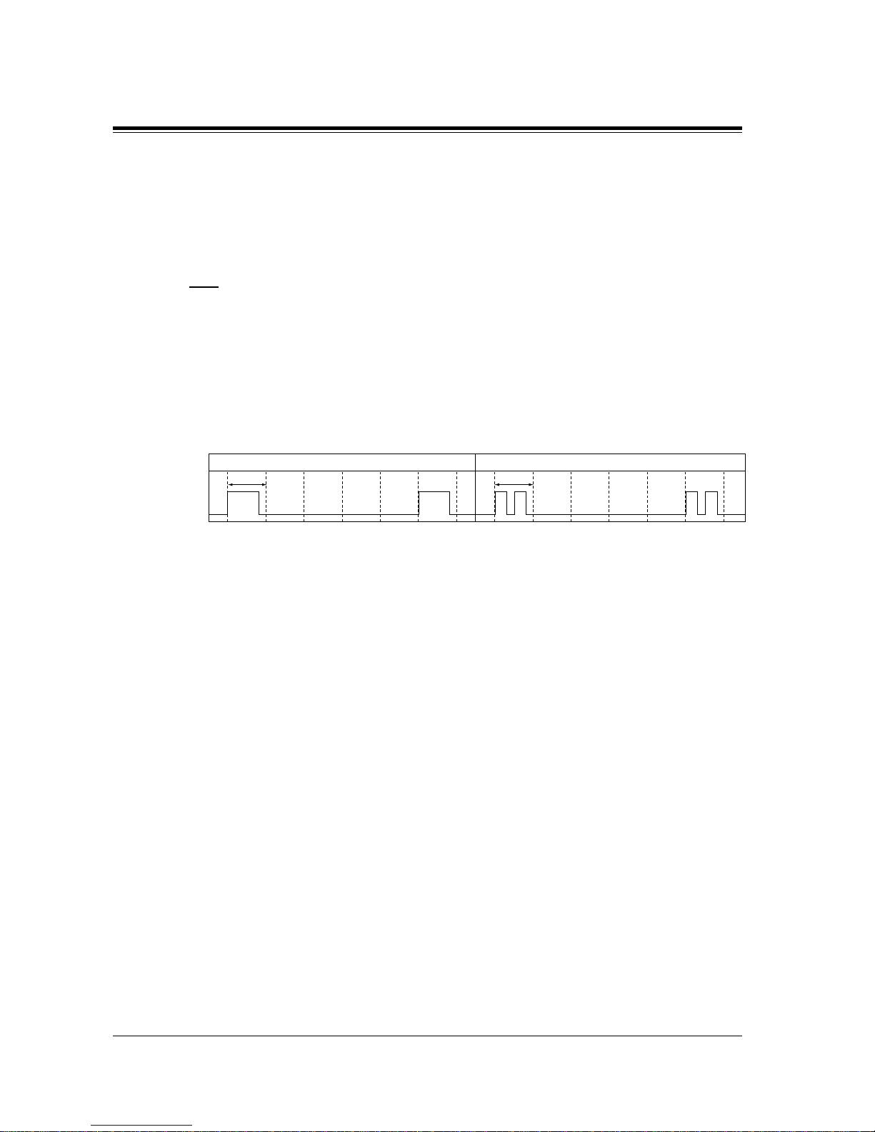
2.4 Installation of Optional Cards and Unit
76 General Installation
2.4.4 16 SLT Line Circuit Unit
T o add ei ght extens ions which contain t wo single li ne telephones, u se the optional 16 SLT Line
Circuit Unit (KX-TD174 ). The uni t can s upport 16 single line t elephones per uni t. Each s ingle
line telephone in the same jac k has di f fe rent e x tensio n number so tha t it can ac t as co mplet ely
different extension like an eXtra Device Port feature.
Note
• Installing this unit allows the eXtra Device Port setting to "Enable" automatically in
system programming [600]. Howev er , assigning "Disabl e" makes a single line telephone
which is connected to the second jack (Jack xx-2) disable to use.
• This unit cannot support the proprietary telephone and Voice Mail Integration features.
• This unit has four DTMF receivers; two receivers in the first eight ports and two
receivers in the last eight ports.
• The Ringing Patt erns for all sin gle line telephones which are connected to the system are
changed as below;
Auxiliary Connection for Power Failure Transfer
When there is a po we r f a il ur e, the first two jacks on this unit can be connected to s pec ific CO
lines mentioned belo w . An auxil iary connection is re quired to implement th is feature. Fo r more
information about the connection between an extension jack to a CO line, refer to Section
2.5 Auxiliary Connection for Power Failure Transfer.
Programming Guide References
[109] Expansion Unit Type
[600] EXtra Device Port
Incoming call from extension
1s
Incoming call from outside line
1s
Page 77
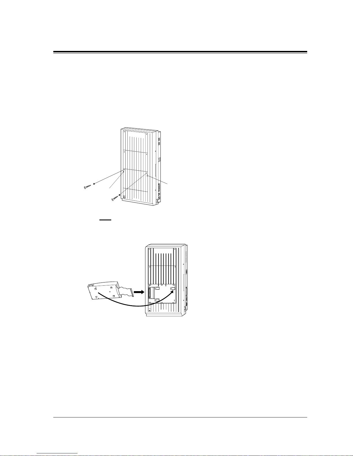
2.4 Installation of Optional Cards and Unit
General Installation
77
2.4.5 Installing Expansion Unit
The following procedures can be used to install the optional expansion units.
The following ste ps 1 thr ough 5 and 7 through 10 are the same for all expa nsi on uni ts. Step 6
is different for e ach unit.
The KX-TD123 2 is illustrated as the main uni t.
1. Loosen the two screws on the cover plate. Insert fingers into the slits to remove the cover
plate.
Note
Any of the cover plates can be removed, as needed.
2. Connect the cabinet cord to the connector in the main unit firmly.
Slit
Slit
D1232
DIGITAL SUPER HYBRID SYSTEM
Panasonic
Panasonic
D1232
DIGITAL SUPER HYBRID SYSTEM
Page 78

2.4 Installation of Optional Cards and Unit
78 General Installation
3. Hook the cabinet on the main unit and slide the cabinet to the left until it i s secured.
4. Loosen the outside screw and slide the cover to the right.
5. Secure the inside screw (included) to fix the cab inet to the main u nit.
Note
Be sure to fix the inside screw to the main unit, or the unit may not work properly.
Panasonic
D1232
DEGITAL SUPER HYBRID SYSTEM
Panasonic
D1232
DIGITAL SUPER HYBRID SYSTEM
Outside screw
Panasonic
D1232
DIGITAL SUPER HYBRID SYSTEM
Inside screw
Page 79
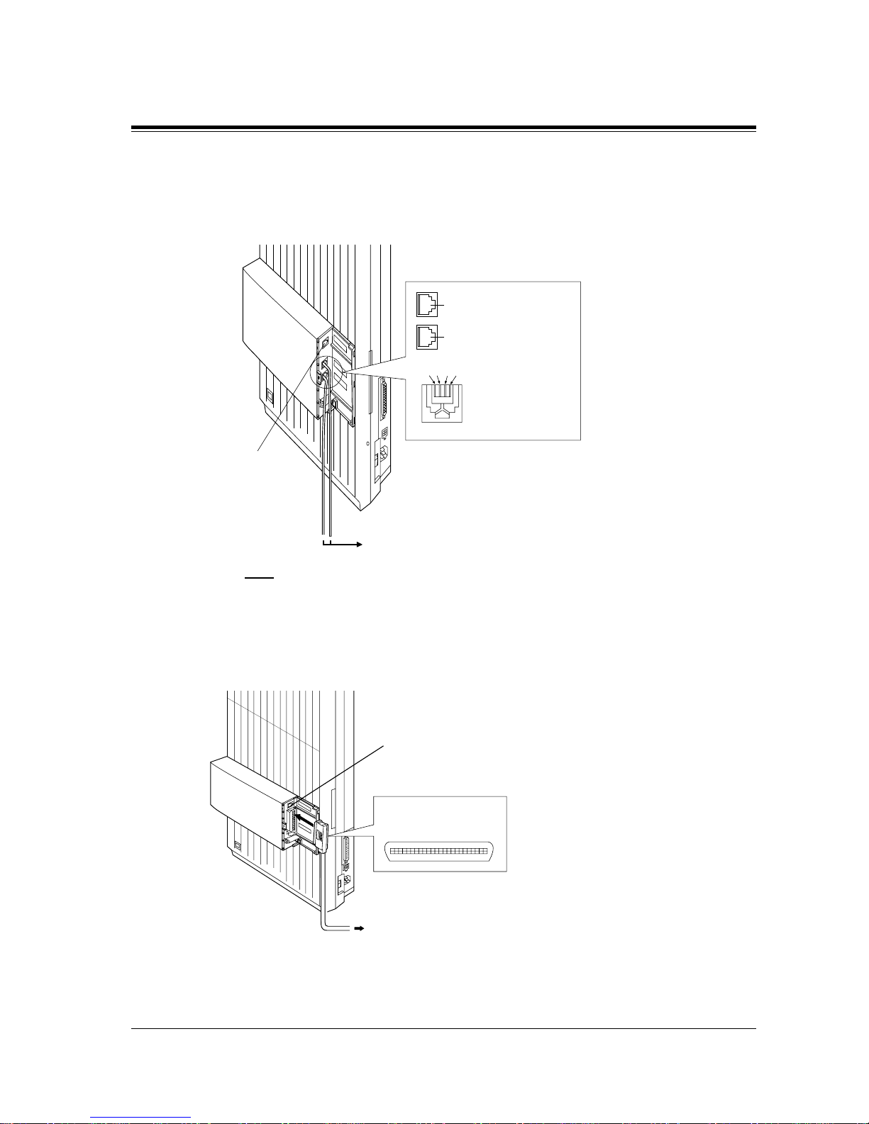
2.4 Installation of Optional Cards and Unit
General Installation
79
6. (If a optio n is to be installed)
If a KX-TD180 is to be installed;
Insert the modular plugs of the telephone line cords (4-conductor wiring) into the
modular jacks on the unit.
Note
• For details about the jack for Power Failure Transfer, refer to Section
2.5.1 Auxiliary Connection for Power Failure Transfer.
If a KX-TD170 and a KX-TD174 is to be installed;
Insert the connector into the jack.
Panasonic
4CO
DIGITAL SUPER HYBRID SYSTEM
PFT ports
2CO w/PFT
2CO
R: Ring
T: Tip
T2 R1 T1 R2
View of TEL Jack (Outside Line)
(T1/R1) (T2/R2)
TD816: Outside Line 05, Outside Line 06
TD1232: Outside Line 09, Outside Line 10
TD816: Outside Line 07, Outside Line 08
TD1232: Outside Line 11, Outside Line 12
Jack for Power
Failure Transfer
To terminal Board or Modular Jacks
from the Central Office
Jack for Power
Failure Transfer
To extensions
(TD816 : Jacks 09 – 16,
TD1232 : Jacks 17 – 24 or 25 – 32)
Panasonic
8EXT
DIGITAL SUPER HYBRID SYSTEM
PFT ports
8EXT
25
50
1
26
Connector type
50-pin (Amphenol 57JE
series or the equivalent)
Page 80

2.4 Installation of Optional Cards and Unit
80 General Installation
Note
• For details about the jack for Power Failure Transfer, refer to Section
2.5.1 Auxiliary Connection for Power Failure Transfer.
• For cable pin numbers to be connected, see "Pin Number Chart" in Section
2.3.2 Extension Connection and "Pin Number Chart for the KX-TD174" on Page
83.
• For fixing the connector, see "Amphenol 57JE Type (screw-attach-type 50-pin
connector) Connection" on Page 81.
7. Tie all of t he cords into a b undl e. If ot her cords are exposed in t he upper cabinets, tie th em
also.
8. Close the cabinet cover and secure the outside screw.
9. Cover the cords with the cord holder (included).
10.Fix the cords to the wall as shown so that the front cover can be opened.
D1232
DIGITAL SUPER HYBRID SYSTEM
Panasonic
Cord holder
D1232
DIGITAL SUPER HYBRID SYSTEM
Panasonic
Page 81
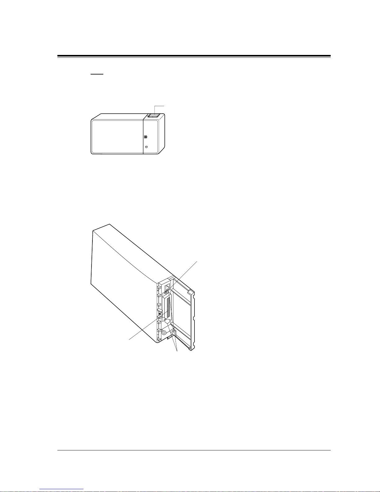
2.4 Installation of Optional Cards and Unit
General Installation
81
Note
If two expansion units are installed, cut the cabinet cover(s) on the lower cabinet(s) to allow
the cords from upper cabinet to go down through the cabinet cover(s). To protect the cords,
smooth the cut edges.
Amphenol 57JE Type (screw-attach-type 50-pin connector) Connection
T o fix the Amphenol 57JE type (scre w-attach type 50-pin conne ctor) to the 8-Station Line Unit,
follow the procedure below.
1. The 50-pin connector (Jack) on the Expansion Unit has two hook-pins. Remove the upper
hook-pin, and take out the screw.
Cut here
Screw
50-pin
connector
Hook-pins
Page 82
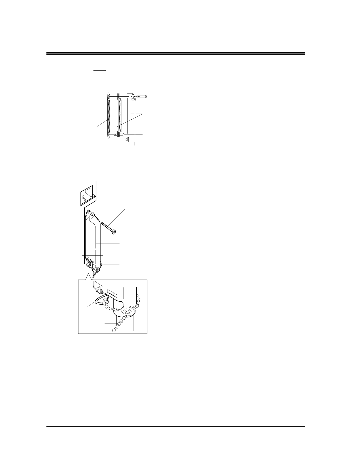
2.4 Installation of Optional Cards and Unit
82 General Installation
Note
When installing a connect or like the type sho wn below , unscre w the lower hook-pin also.
Then drive both accessory screws.
2. To attach the Amphenol 57JE type (Plug) to the connector, drive the accessory screw into
the upper part.
Fasten the accessory wire tie around the lower hook-pin and the Amphenol 57JE type, as
shown.
Accessory screw
Amphenol 57JE type
Accessory
screw
50-pin
connector
Accessory screw
Amphenol 57JE type
Accessory wire tie
57JE type
Hook-pin
Accessory
wire tie
Page 83

2.4 Installation of Optional Cards and Unit
General Installation
83
CONN
PIN
Pin Number Chart for the KX-TD174
26
1
27
2
28
3
29
4
30
5
31
6
32
7
33
8
34
9
35
10
36
11
37
12
38
13
39
14
40
15
41
16
1
2
3
4
5
6
7
8
9
10
11
12
13
14
15
16
17
18
19
20
21
22
23
24
25
26
27
28
29
30
31
32
T
R
T
R
T
R
T
R
T
R
T
R
T
R
T
R
T
R
T
R
T
R
T
R
T
R
T
R
T
R
T
R
T
R
T
R
T
R
T
R
T
R
T
R
T
R
T
R
T
R
T
R
T
R
T
R
T
R
T
R
T
R
T
R
Jack. 09-1
Jack. 10-1
Jack. 11-1
Jack. 12-1
Jack. 13-1
Jack. 14-1
Jack. 15-1
Jack. 16-1
Jack. 09-2
Jack. 10-2
Jack. 11-2
Jack. 12-2
Jack. 13-2
Jack. 14-2
Jack. 15-2
Jack. 16-2
Jack. 25-1
Jack. 26-1
Jack. 27-1
Jack. 28-1
Jack. 29-1
Jack. 30-1
Jack. 31-1
Jack. 32-1
Jack. 25-2
Jack. 26-2
Jack. 27-2
Jack. 28-2
Jack. 29-2
Jack. 30-2
Jack. 31-2
Jack. 32-2
Clip
Terminal
(KX-A205)
No.
For KX-TD816
Jack No.9-16 Jack No.25-32
For KX-TD1232
(Expansion 2)
T
R
T
R
T
R
T
R
T
R
T
R
T
R
T
R
T
R
T
R
T
R
T
R
T
R
T
R
T
R
T
R
Jack. 17-1
Jack. 18-1
Jack. 19-1
Jack. 20-1
Jack. 21-1
Jack. 22-1
Jack. 23-1
Jack. 24-1
Jack. 17-2
Jack. 18-2
Jack. 19-2
Jack. 20-2
Jack. 21-2
Jack. 22-2
Jack. 23-2
Jack. 24-2
For KX-TD1232
(Expansion 1)
Jack No.17-24
Page 84
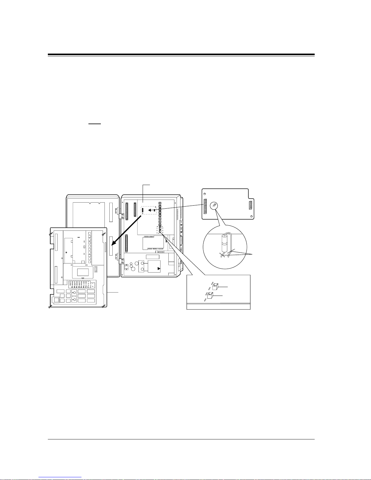
2.4 Installation of Optional Cards and Unit
84 General Installation
2.4.6 Pay Tone Card Installation
Installing to the Initial CO Line Card
1. Loosen four screws for KX-TD816 or eight screws fo r KX-TD1232 to open the inside cov er
of the main unit.
Note
If any cards, units, or cords are installed in the main unit, remove them beforehand.
2. Attach the Pay T one Card(s) (KX-TD189 ) to the CO Line Card, with the spacers (Accessa ry
included).
One Pay Tone Card for KX-TD816, and up to two Pay Tone Cards for KX-TD1232 can be
installed to t he initial CO Line Card.
CO03,04
CO01,02
OPJPB OPJPC OPJPD
OPJPA
J200
J200
Cut here
CO Line Card
Inside Cover
Pay Tone Card
CO Line Card
OPJPA – D
KX-TD816
Page 85
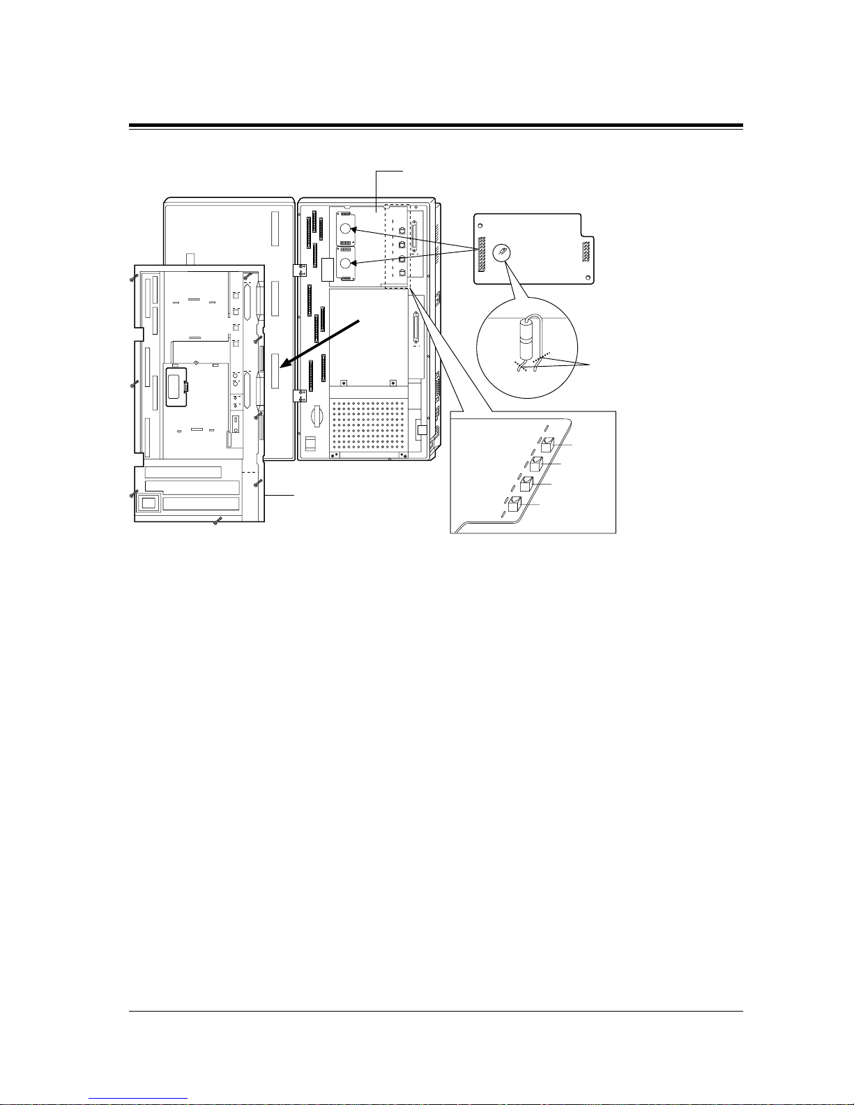
2.4 Installation of Optional Cards and Unit
General Installation
85
3. If you do not cut the wire of the J200 in Pay Tone Card, the detected mode is 16 KHz. If
you cut the wire of the J200 in Pay Tone Card (Open Mode), the dete cte d mode is 12 KHz.
4. After installing the Pay Tone Card, if you hear a noise of the pay-tone signal, cut th e option
Jumper Wires, OPJPA through OPJPH, in the CO Card.
KX-TD816: OPJPA through OPJPD corresponds to outside line (CO) 01 through 04
respectively.
KX-TD1232: OPJPA through OPJPH corresponds to outside line (CO) 01 through 08
respectively.
<Example>
– When you install the Pay Tone Card A, you will detect the pay-tone signal from outside
line (CO) 01 through 04, and cut the corresponding option Jumper Wires, if needed.
– When you install the Pay Tone Card B, you will detect the pay-tone signal from outside
line (CO) 05 through 08, and cut the corresponding option Jumper Wires, if needed.
5. Put the inside cover back on the main unit and secure the screws.
J200
J200
CO07,08
CO05,06
CO03,04
CO01,02
OPJPB OPJPC OPJPD OPJPE OPJPF OPJPG OPJPH
OPJPA
B
A
Cut here
CO Line Card
Inside Cover
Pay Tone Card
CO Line Card
OPJPA – H
KX-TD1232
Page 86
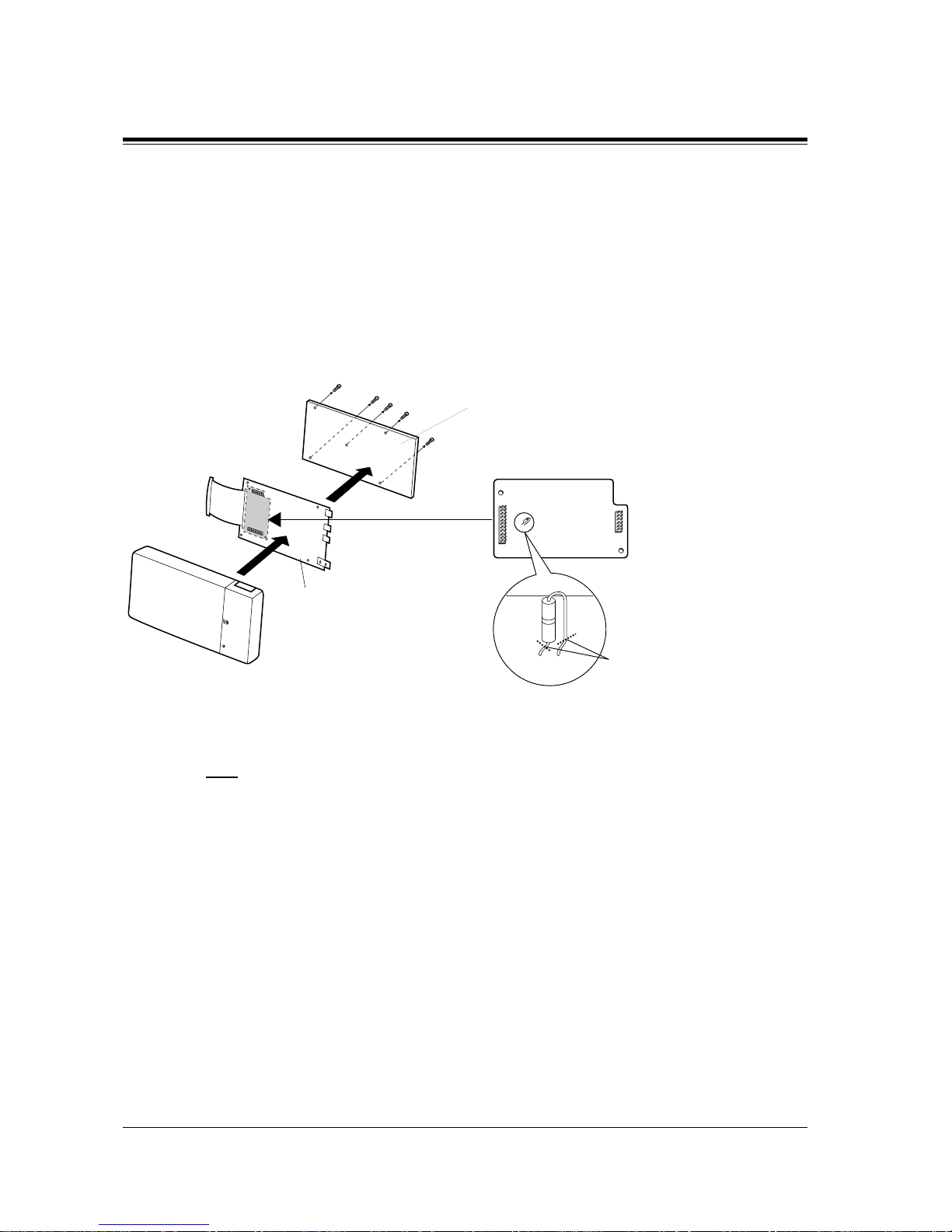
2.4 Installation of Optional Cards and Unit
86 General Installation
Installing to the Optional 4-CO Line Unit
The followi ng pr oce dur es mus t be done before installing the 4-CO Line Unit (KX-TD180) to
the main unit.
1. Loosen five screws located on the rear of the 4-CO Line Unit.
2. Remove the back plate and take out the P-board.
3. Attach the Pay Tone Card (KX-TD189) to the P-board, fitting the connectors.
4. Put the P-board back into the cabinet and fix the rear plate with the five screws.
5. If you do not cut the wire of the J200 in Pay Tone Card, the detected mode is 16 KHz. If
you cut the wire of the J200 in pay-tone card (Open Mode), the detected mode is 12 KHz.
Note
To install the 4-CO Line Unit to the main unit, refer to Section 2.4.5 Installing Expansion
Unit.
Programming Guide References
[423] Pay Tone Assignment
Features Guide References
Hotel Applica tion
Incoming Outside Call Information Display
4CO
DIGITAL SUPER HYBRID SYSTEM
J200
J200
Cut here
Back plate
P-board
Pay Tone Card
Page 87
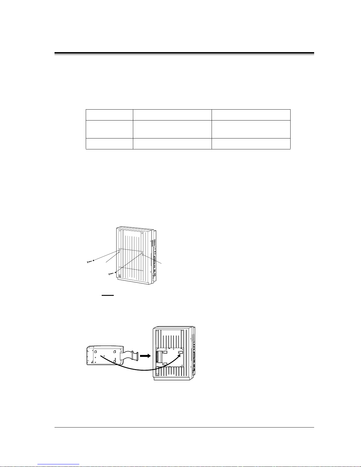
2.4 Installation of Optional Cards and Unit
General Installation
87
2.4.7 DISA Card / Unit and Remote Card / Unit Installation
The DISA Card (KX-TD191 and KX-TD199), DISA Unit (KX-TD190), Remote Card (KXTD196), High Speed Remote Card (KX-TD197) and Remote Unit (KX-TD198) can be
installed as follows.
The DISA Unit and the Remote Unit can also be attached with other line expansion unit.
KX-TD816
1. Loosen the two screws on the cover plate. Insert your fingers into the slits to remove the
cover plate.
Note
There are two cover plates. Any of them can be removed, as needed.
2. Connect the cabinet cord to the connector in the main unit firmly.
Main Unit For DISA feature For remote access
KX-TD816 KX-TD190,
KX-TD198 with KX-TD199
KX-TD198,
KX-TD190 with KX-TD197
KX-TD1232 KX-TD191 KX-TD196, KX-TD197
Installing the DISA Unit (KX-TD190) or Remote Unit (KX-TD198)
D816
DIGITAL SUPER HYBRID SYSTEM
Panasonic
Slit
Slit
Panasonic
D816
DIGITAL SUPER HYBRID SYSTEM
Panasonic
Page 88
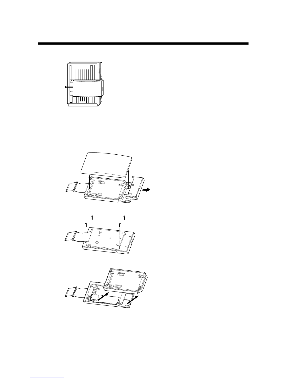
2.4 Installation of Optional Cards and Unit
88 General Installation
3. Hook the cabinet onto the main unit and slide the cabinet to the left until it is secured.
It is possible to install the required card in the unit before installing the unit to the main unit.
The illustrat ions below are the examples for installing the DISA C ard to the Remot e Unit.
1. Open the front cover of the unit, slide the side cover to the right and remove it.
2. Turn over the unit and remove the four screws.
3. Turn over the unit again and remove the inside cover.
Installing the DISA Card (KX-TD199) to the Remote Unit (KX-TD198) /
Installing the High Speed Remote Card (KX-TD197) to the DISA Unit (KX-TD190)
Panasonic
D816
DIGITAL SUPER HYBRID SYSTEM
Page 89
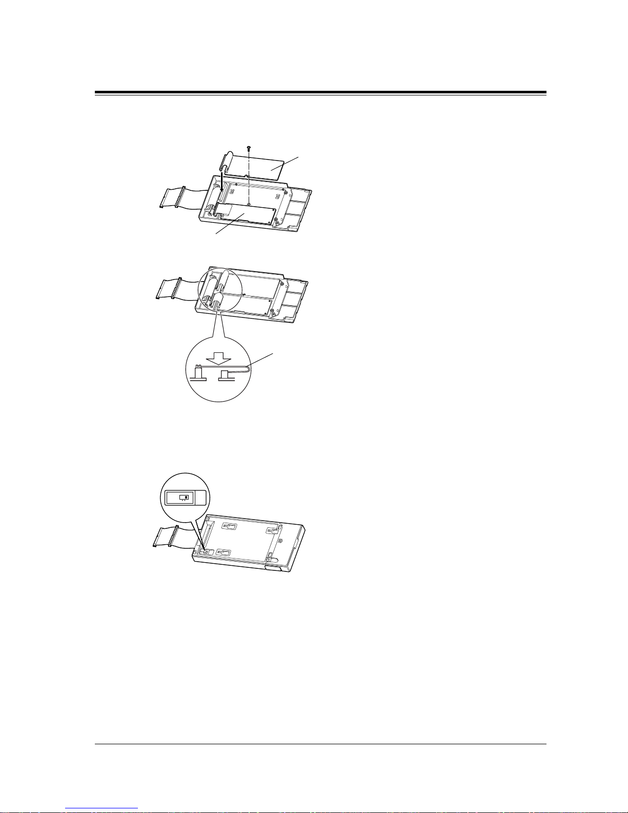
2.4 Installation of Optional Cards and Unit
General Installation
89
4. Install the card, secure the screw (included with the unit) and connect the cable to the
connector.
5. Flatten the cable to replace the inside cover properly.
6. Replace the inside cover and secure the four screws on the back. Also, replace the side
cover.
7. Set the MODE switch to 2.
8. Replace the front cover.
9. Install the unit to the main unit.
DISA Card
Remote Card
Cable
Side View
MODE
12
Page 90
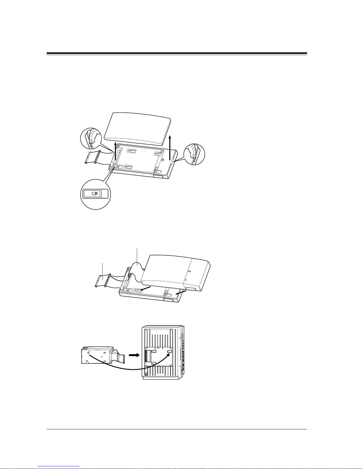
2.4 Installation of Optional Cards and Unit
90 General Installation
1. Remove the front cover of the DISA or Remote Unit.
The KX-TD198 users must set the MODE switch to 2.
2. Attach the expansion unit to the DISA or Rem ote Unit as shown below. Be sure to connect
the cabinet cords by insert ing the e xpa nsion uni t cabine t cord thr ough the sl ot in the DISA
or Remote Unit.
3. Remove the cover plate and connect the cabinet cord to the connector in the main unit
firmly.
Attaching another line expansion unit to the DISA Unit (KX-TD190) or Remote Unit (KXTD198) and install them to the system
MODE
12
Expansion unit cabinet cord
DISA / Remote unit
cabinet cord
Panasonic
D816
DIGITAL SUPER HYBRID SYSTEM
Panasonic
Page 91
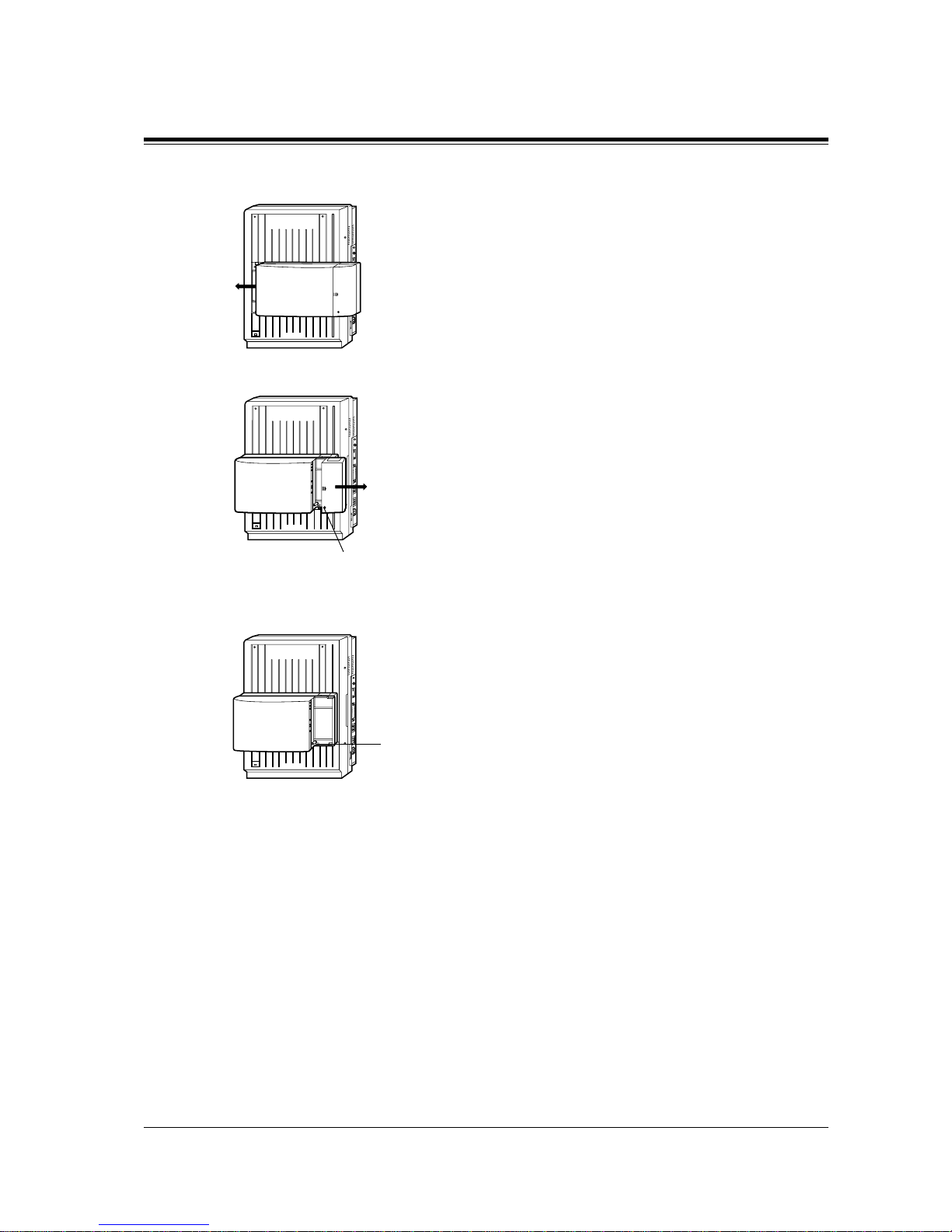
2.4 Installation of Optional Cards and Unit
General Installation
91
4. Hook the cabinets onto the main un it and s lide t he cab inets t o the l eft unt il the y are secu red.
5. Loosen the outside screw of the expansion unit and slide the cover to the right.
6. Secure the inside screw (included with the DISA or Remote Unit) to fix the cabin et to the
main unit.
7. Tie all of the cords into a bundle. If other cords are exposed from the upper cabinets, tie
them also.
8. Close the cabinet cover and secure the outside screw.
9. Cover the cord s with the c ord holder. If two cabinets are connecte d together a nd attached to
the main unit, use the cord holder included with the DISA or Remote Unit.
Panasonic
D816
DIGITAL SUPER HYBRID SYSTEM
Panasonic
D816
DIGITAL SUPER HYBRID SYSTEM
Outside screw
Panasonic
D816
DIGITAL SUPER HYBRID SYSTEM
Inside screw
Page 92
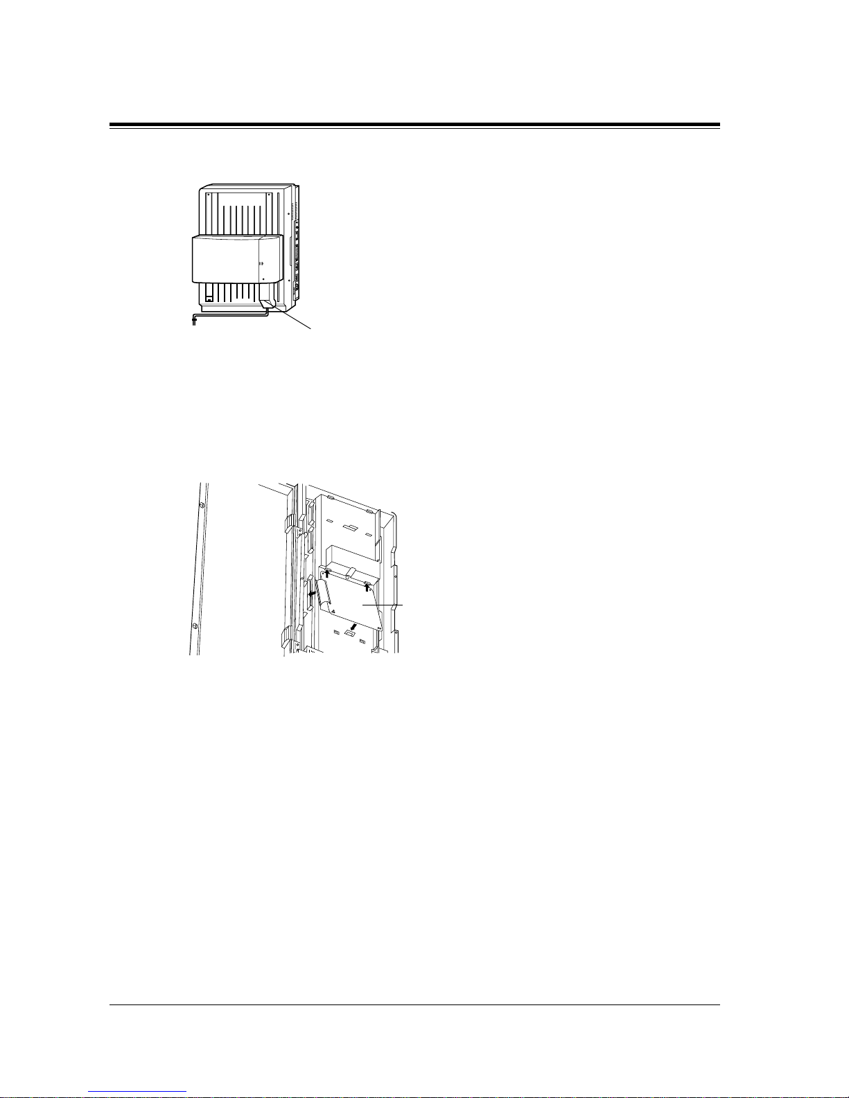
2.4 Installation of Optional Cards and Unit
92 General Installation
10.Fix the cords to the wall as shown here, so that the front cover can be opened.
KX-TD1232
1. Insert the upper side of the DISA Card into the two hooks on the main unit.
2. Press down the two corners of the lower side of the DISA Card.
3. Connect the cord to the DISA Card Connector.
Features Guide References
Direct Inward System Access (DISA)
Installing the DISA Card (KX-TD191)
Panasonic
D816
DIGITAL SUPER HYBRID SYSTEM
Panasonic
Cord holder
DISA Card
Page 93
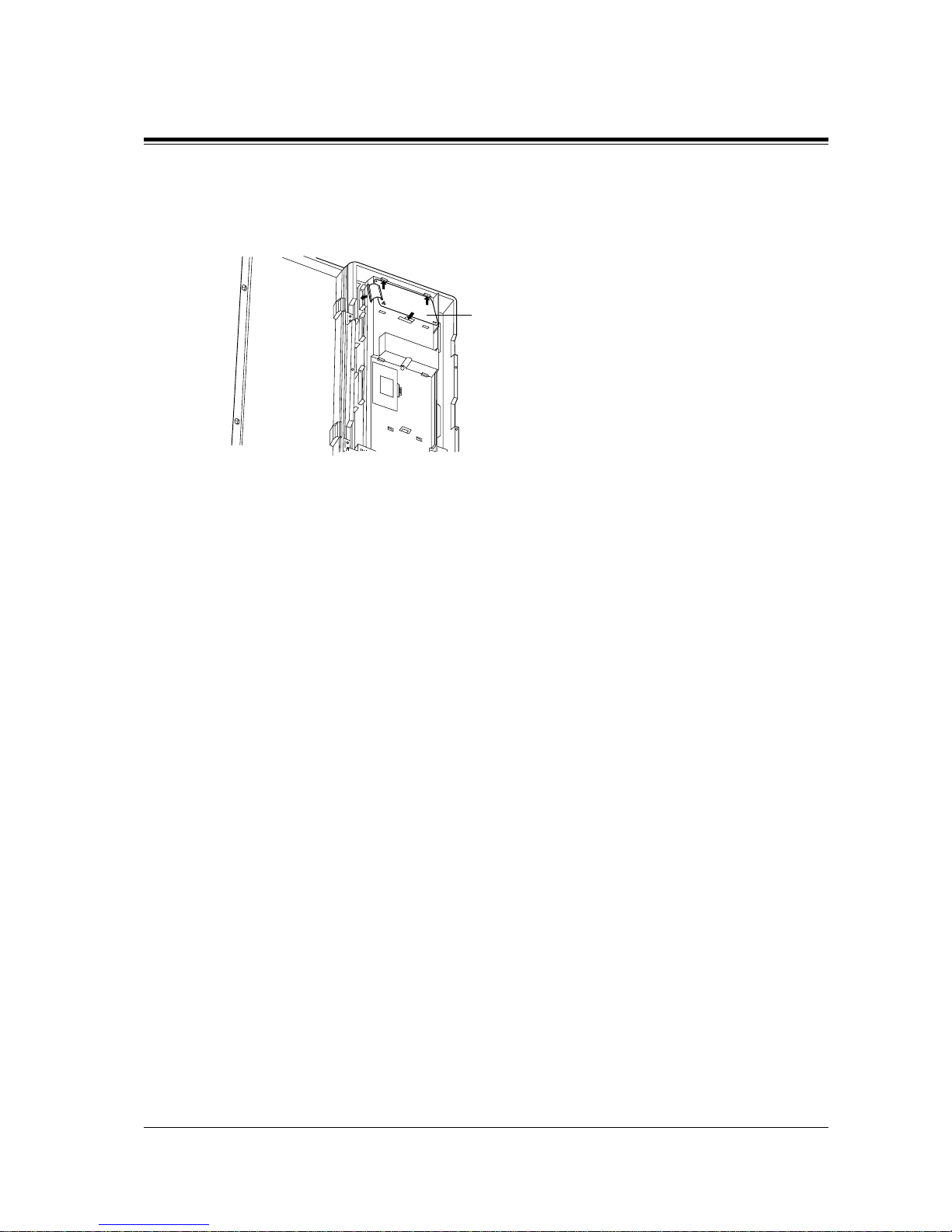
2.4 Installation of Optional Cards and Unit
General Installation
93
1. Insert the upper side of the Remote Card into the two hooks on the main unit.
2. Press down the two corners of the lower side of the Remote Card.
3. Connect the cord to the Remote Card Connector.
Programming Guide References
[107] System Password
[813] Floating Number Assignment
[814] Modem Standard
[817] KX-TD197 Baud Rate Set
Features Guide References
System Programming and Diagnosis with Personal Computer
Installing the Remote Card (KX-TD196) or High Speed Remote Card (KX-TD197)
Remote Card
Page 94
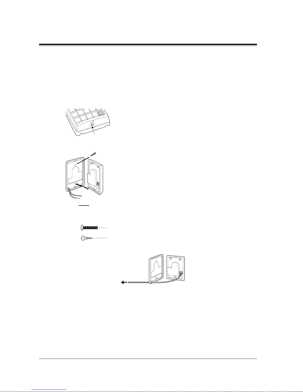
2.4 Installation of Optional Cards and Unit
94 General Installation
2.4.8 Doorphone and Door Opener Connection
To connect up to two doorphones (KX-T30865) a nd up to tw o door opener s (us er -su pplied ), a
Doorphone Card (KX-TD160) is required.
Installing the Doorphone
1. Loosen the screw to separate the doorphone into two halves.
2. Install the base cover to the wall with two scr ews.
Note
T wo ki nds of scre ws are incl uded. Please choo se the appropri ate one depending on you r
wall type:
3. Connect the wires to the screws located in the front cover.
4. Secure both halves together and re-install the screw.
screw
Panasonic
Type 1: When the doorphone plate has been fixed to the wall.
When you wish to install the doorphone directly to the wall.Type 2:
To the terminal box (See
"Wiring of the Doorphone".)
Page 95
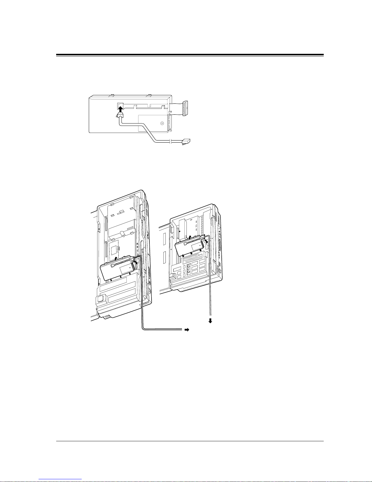
2.4 Installation of Optional Cards and Unit
General Installation
95
Doorphone Card Installation
1. Connect a 4-conductor modular connector to the Doorphone Card Cabinet, and pass the
cord through the groove in the cabinet.
2. Attach the Doorphone Card Cabinet to the main unit and press down.
3. Connect the cord to the Doorphone Card Connector.
KX-TD1232 KX-TD816
To Terminal Box
Page 96
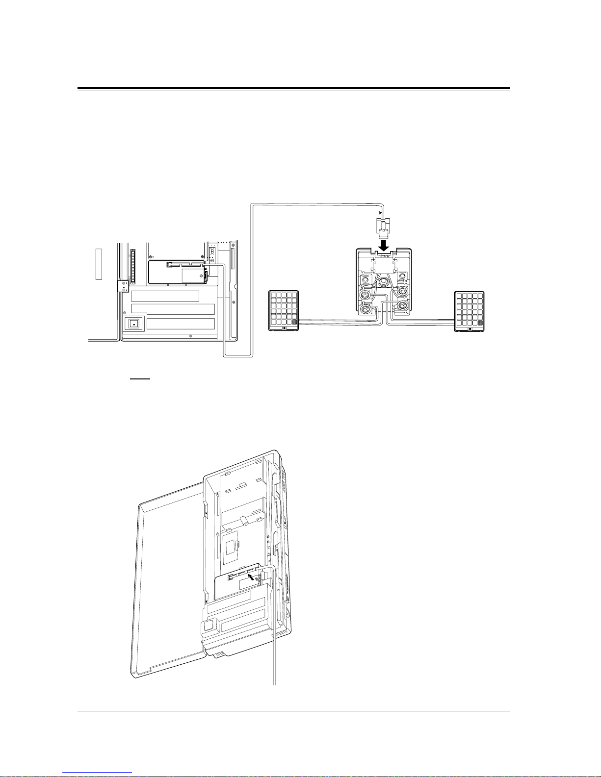
2.4 Installation of Optional Cards and Unit
96 General Installation
Wiring of the Doorphone
1. Connect the Doorphone Card to the terminal box using a 4-conductor modular connector.
2. Connect the wires of doorphone 1 to the red and green screws of the terminal box.
3. Connect the wires of doorphone 2 to the yellow and black screws of the terminal box.
Note
The KX-TD1232 is illustrated as the main unit.
Connecting Door Openers
1. Loosen the screw to remove the cover.
4-conductor wiring
is required.
Doorphone 1
(KX-T30865)
Doorphone 2
(KX-T30865)
Yellow
Red
Black
Green
Terminal Box
Panasonic
Panasonic
Page 97
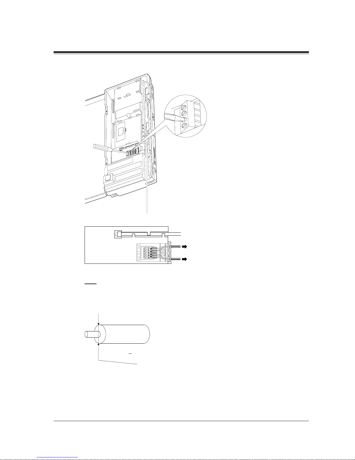
2.4 Installation of Optional Cards and Unit
General Installation
97
2. Loosen the screws on the terminal stri p.
3. Insert the wires coming from the door openers into holes and tighten the screws.
Note
• The KX-TD1232 is illustrated as the main unit.
• For wiring, UL 1015, AWG 22 twisted wire or the equivalent is recommended.
• The wire should be between 1.2 mm and 2.4 mm in diameter including the coating.
To door
opener
2
To door
opener 1
D=1.2 mm 2.4 mm
Page 98
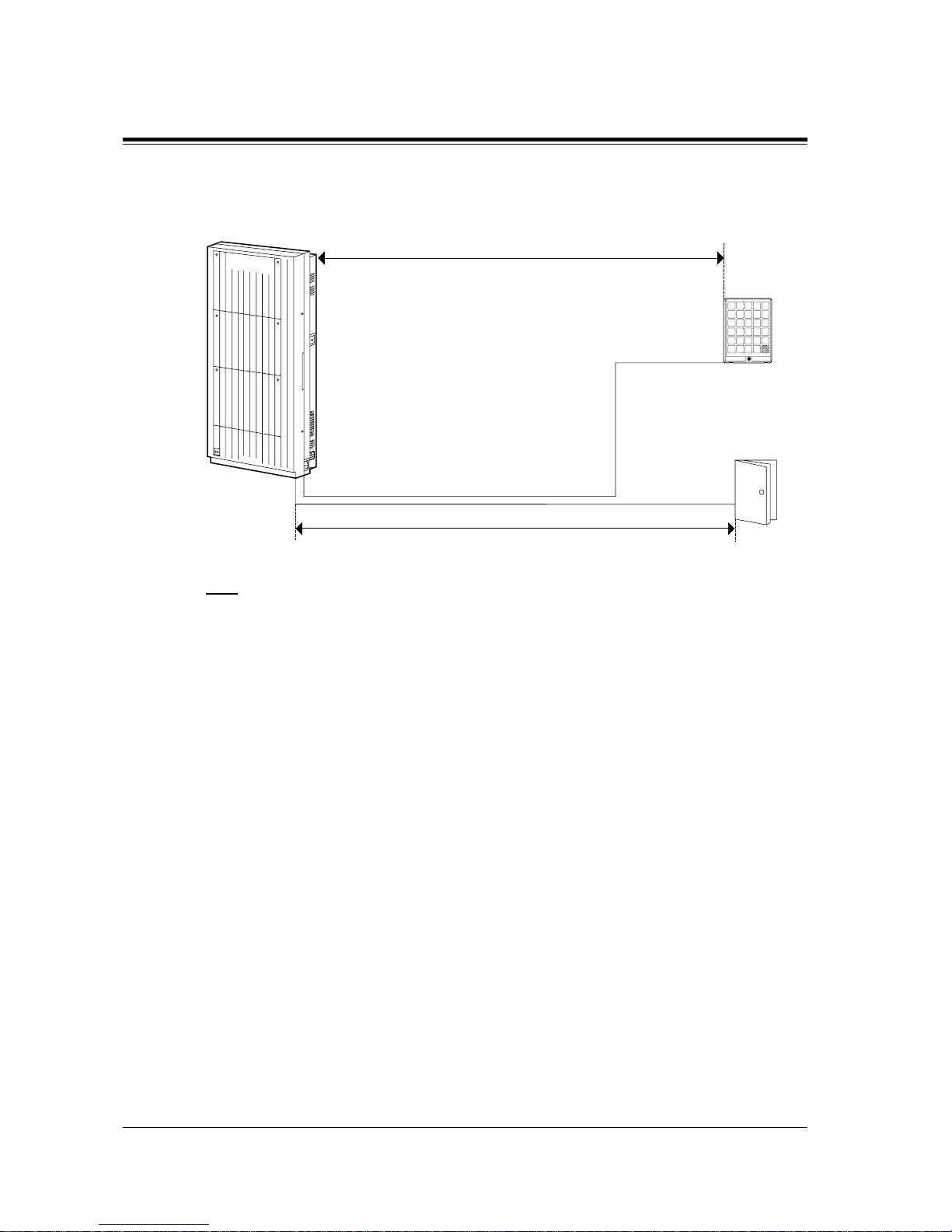
2.4 Installation of Optional Cards and Unit
98 General Installation
Maximum cabling distance of the doorphone and the door opener line
The maximum length of the doorphone and door opener line that connects to the main unit is
shown below:
Note
The KX-TD1232 is illustrated as the main unit.
Programming Guide References
[607-608] Doorphone Ringing Assignment – Day / Night
[663-664] PS Doorphone Ringing Assignment – Day / Night
Features Guide References
Door Opener
Doorphone Call
26 AWG: Under 70 m
24 AWG: Under 113 m
22 AWG: Under 180 m
Doorphone
KX-T30865
Door Opener
22 AWG: Under 180 m
D1232
DIGITAL SUPER HYBRID SYSTEM
Panasonic
Panasonic
Page 99
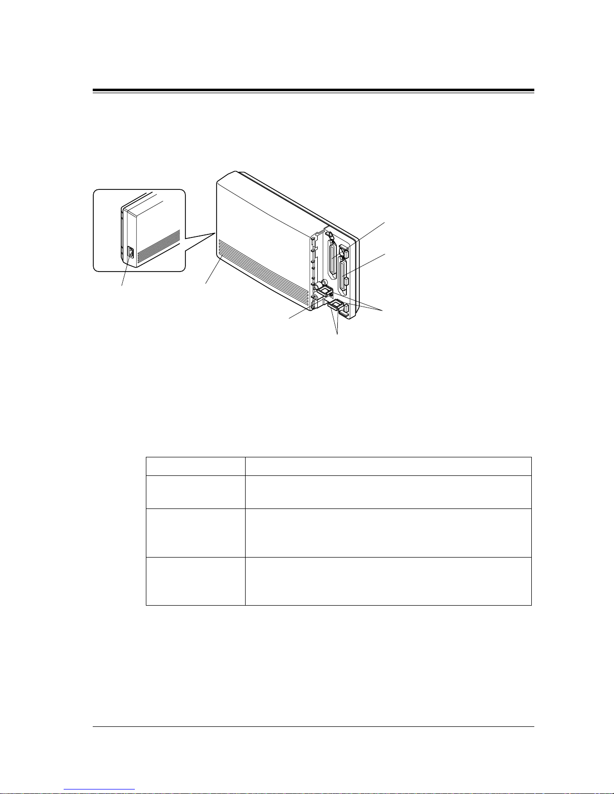
2.4 Installation of Optional Cards and Unit
General Installation
99
2.4.9 SLT Message Waiting Lamp Adaptor Unit Connection
Name and Locations
Specifications
1. General Description
Capacity Corresponding extensions 16
Control Method CPU: One-chip microcomputer
Interface: 1-APT Interface
Power Supplies Primary Power
Secondary
230 VAC, 50 Hz
Station Supply Voltage: + 85 V
Circuit Voltage: + 5V, + 15 V
Connectors Stations
DC Input/Output
Interface
50-pin Amphenol Connector
4-pin Connector
Side View
AC inlet
Power light
Ground terminal
Binders
DC input/output
Connector (TO SYSTEM
)
Connector (TO EXTN
)
connector
Page 100
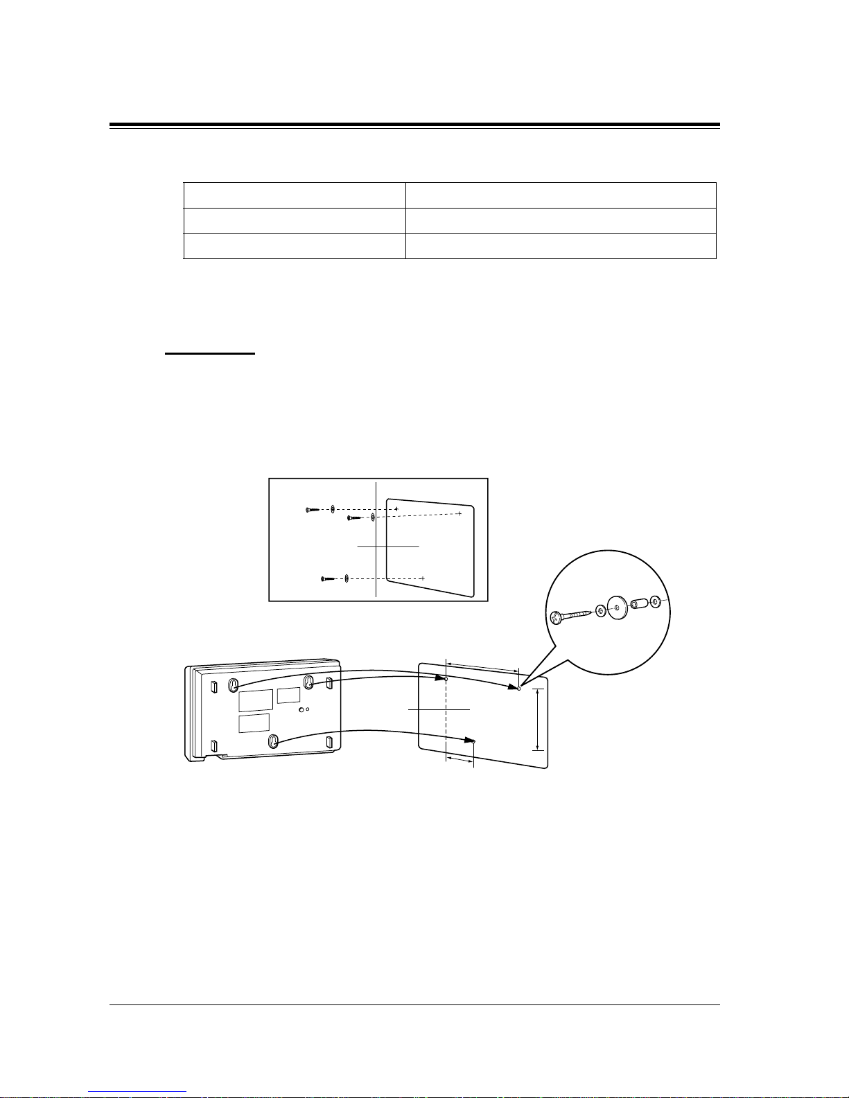
2.4 Installation of Optional Cards and Unit
100 General Installation
2. Characteristics
WARNING
THIS UNIT MAY ONLY BE INSTALLED AND SERVICED BY QUALIFIED
SERVICE PERSONNEL.
Wall Mounting
This unit can be mounted to a wall. Refer to Section 2.2.3 Wall Mounting for details.
DC Power Supply to Stations 85 V, 1.2 mA (max)
Primary Power 230 VAC, 50 Hz, 0.8 A (max)
*1
*1
This is the maximum current when th ree TD194s are connected by DC input/output interfaces (only the main
TD194 is connected to an AC outlet).
Environmental Requirements 0 °C – 40 °C, 10 % – 90 % rel. hum.
Template
Template
148 mm
106 mm
71 m
m
or
 Loading...