


Panasonic TC-L32C5, TC-L32C5X, TC-32LC54, TC-L3252C Schematic
ORDER NO.MTNC120449CE
B01 Canada: B61
LCD TV
Model No. TC-L32C5
TC-32LC54
TC-L32C5X
TC-L3252C
©Panasonic Corporation 2012.
Unauthorized copying and distribution is a
violation of law.

CONTENTS
1. Safety precautions .................................................................................................
2. Alignment instructions and method of software upgrading.....................................
3. Working principle analysis of the unit...................................................................
4. Block diagram ......................................................................................................
5. IC block diagram..................................................................................................
6. Wiring diagram ...................................................................................................
7. Troubleshooting guide..........................................................................................
8. Exploded View.....................................................................................................34
9. Replacement Parts List........................................................................................36
10. Boards Layout....................................................................................................39
3
5
14
15
16
28
30
2

Attention:
please read the following points carefully.
Safety precautions
This service manual is only for service personnel to take reference with. Before
servicing
1. Instructions
Be sure to switch off the power supply before replacing or welding any components or
inserting/plugging
process!):
a) Do not touch here and there by hand at will;
b) Be sure to use anti static electric iron;
c) It’s a must for the welder to wear anti static gloves.
Please refer to the detailed list before replacing components that have special safety requirements.
not change the specs and type at will.
Do
in
connection wire Anti static measures to be taken (throughout the entire production
2. Points for attention in servicing of LCD
2.1 Screens are different from one model to another and therefore not interchangeable. Be sure to
Use the screen of the original model for replacement.
2.2 The operation voltage of LCD screen is
protecting
right
yourself and the machine when testing the system in the course of normal operation or
after the power is switched off. Please do not touch the circuit or the metal part of the module
high voltage. Be
sure to take proper measures in
That is in operation mode. Relevant operation is possible only one minute after the power is switched
off.
2.3 Do not use any adapter that is not identical with the TV set. Otherwise it will cause fire or damage
to the set.
2.4 Never operate the set or do any installation work in bad environment such as wet bathroom,
laundry,
Otherwise
2.5 If any foreign substance such as water, liquid, metal slices or other matters happens to fall into the
module, be sure to cut the power off immediately and do not move anything on the module lest it should
cause fire or electric shock due to contact with the high voltage or short circuit.
2.6 Should there be smoke, abnormal smell or sound from the module, please shut the power off at
once.
power
2.7 Do not pull out or plug in the connection wire when the module is in operation or just after the
power
circuit.
2.8 When operating or installing LCD please don’t subject the LCD components to bending, twisting or
extrusion, collision lest mishap should result.
2.9 As most of the circuitry in LCD TV set is composed of CMOS integrated circuits, it’s necessary to
pay attention to anti statics. Before servicing LCD TV make sure to take anti static measure and
ensure
kitchen, or nearby fire source, heating equipment and devices or exposure to sunlight etc.
bad effect will result.
Likewise, if the screen is not working after the power is on or in the course of operation, the
must be cut off immediately and no more operation is allowed under the same condition.
is
off because in this case relatively high voltage still remains in the capacitor of the driving
Please wait at least one minute before the pulling out or plugging in the connection wire.
full grounding for all the parts that have to be grounded.
2.10 There are lots of connection wires between parts behind the LCD screen. When servicing or
moving
would
If the connection wires, connections or components fixed by the thermo tropic glue need to disengage
when service, please soak the thermo tropic glue into the alcohol and then pull them out in case of
damage.
the set please take care not to touch or scratch them. Once they are damaged the screen
be
unable to work and no way to get it repaired.
3
2.11 Special care must be taken in transporting or handling it. Exquisite shock vibration may lead to
breakage
before
2.12 For the storage make sure to put it in a place where the environment can be controlled so as to
prevent
prolonged
place.
of
screen glass or damage to driving circuit. Therefore it must be packed in a strong case
the transportation or handling.
the temperature and humidity from exceeding the limits as specified in the manual. For
storage, it is necessary to house it in an anti-moisture bag and put them altogether in one
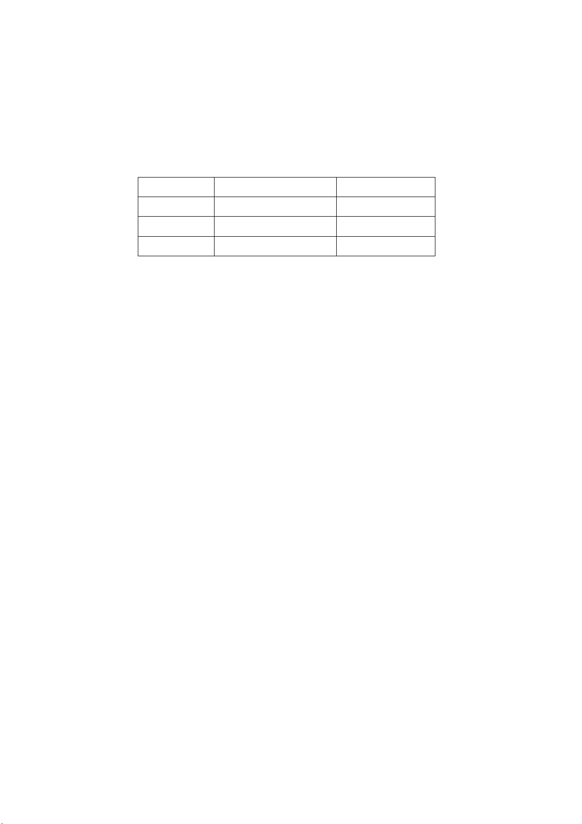
The ambient conditions are tabulated as follows:
Temperature
Scope for operation
0
~ + 40
oC
Humidity
2.13
Display of a fixed picture for a long time may result in appearance of picture residue on the
as
screen,
of LCD screen. This phenomenon doesn’t represent failure. This “ghost shadow” may remain
in the picture for a period of time (several minutes). But when operating it please avoid displaying still
picture in high brightness for a long time.
commonly called “ghost shadow”. The extent of the residual picture varies with the maker
Scope for storage
Scope for operation
Scope for storage
-20 ~
+ 60oC
20% ~
5% ~ 90%
90
%
3. Points for attention during installation
3.1 The front panel of LCD screen is of glass. When installing it please make sure to put it in place.
3.2 For service or installation it’s necessary to use specified screw lest it should damage the screen.
3.3 Be sure to take anti dust measures. Any foreign substance that happens to fall down between the
screen and the glass will affect the receiving and viewing effect
3.4 When dismantling or mounting the protective partition plate that is used for anti vibration and
insulation
3.5 Be sure to protect the cabinet from damage or scratch during service, dismantling or mounting.
please take care to keep it in intactness so as to avoid hidden trouble.
4
2. Alignment instructions
(1) Test equipment
VG-859 (YPbPr, VGA, HDMI signal generator)
FLUKE 54200(TV signal generator)
CA210
(white balancer)
(2) Power test
Connect main board, power board and IR board according the wiring diagram, connect
the power and press power key (Remote controller or Keypad) button to turn on the TV.
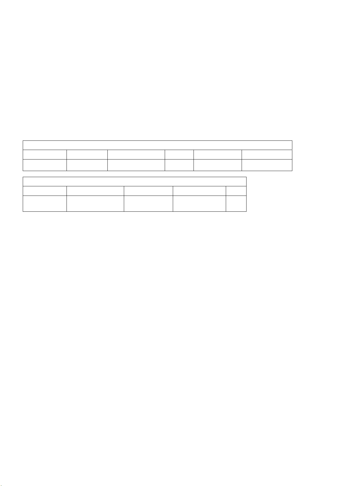
a) Test the pin voltage of P802/power board , the data is shown in table1:
Table1
voltage data of P802
For 32”
P802 Pin1,2 Pin3,4 Pin5,6,7 Pin8,9 Pin10,11
Voltage GND 11.4V~12.6V GND 11.4V~12.6V 4.75V~5.25V
For 32”
Pin12 Pin13 Pin 14 Pin15 Pin16
On:2.5V-5.25V
Off: 0-0.5V
Normal:0V~0.5V
Abnormal :Open drain
On:2.5V-5.25V
Off: 0-0.5V
Duty 20%~100% NC
5
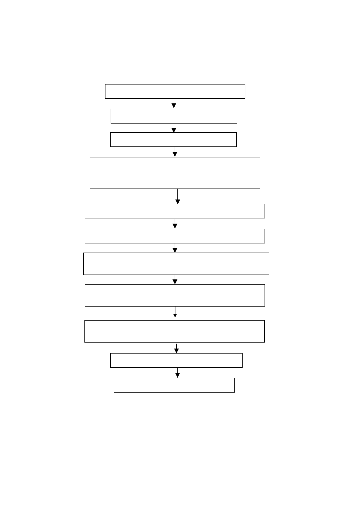
(3) Alignment flow-chart
The alignment flow-chart is shown as fig-1
Connect to the center signal source and check each
Function of TV (station leaking, analog control, etc.)
Check the output of earphone and speaker.
Check if DDC, HDCP KEY, FLASH are written
Combined test for general assembly
White balance adjustment
Input AV signal and check the function
Input HD signal and check the function of YPbPr
Input VGA signal and check if the display is normal, check
the function (analog control), horizontal/vertical center, etc.
Input USB signal and check if the display is normal, check
the function (analog control), horizontal/vertical center, etc.
Input HDMI signal and check if the display is normal, check
the function (analog control), horizontal/vertical center, etc.
Preset ex-factory
Check the accessories and packing
Fig-1 adjustment flow-chart
6
(4) Adjustment instruction
At any input source then press the “←”, “EXIT” and “OK” (Remote control within 1 sec) to enter factory mode
During Factory menu, if “MENU” key is pushed, system will exit factory mode.
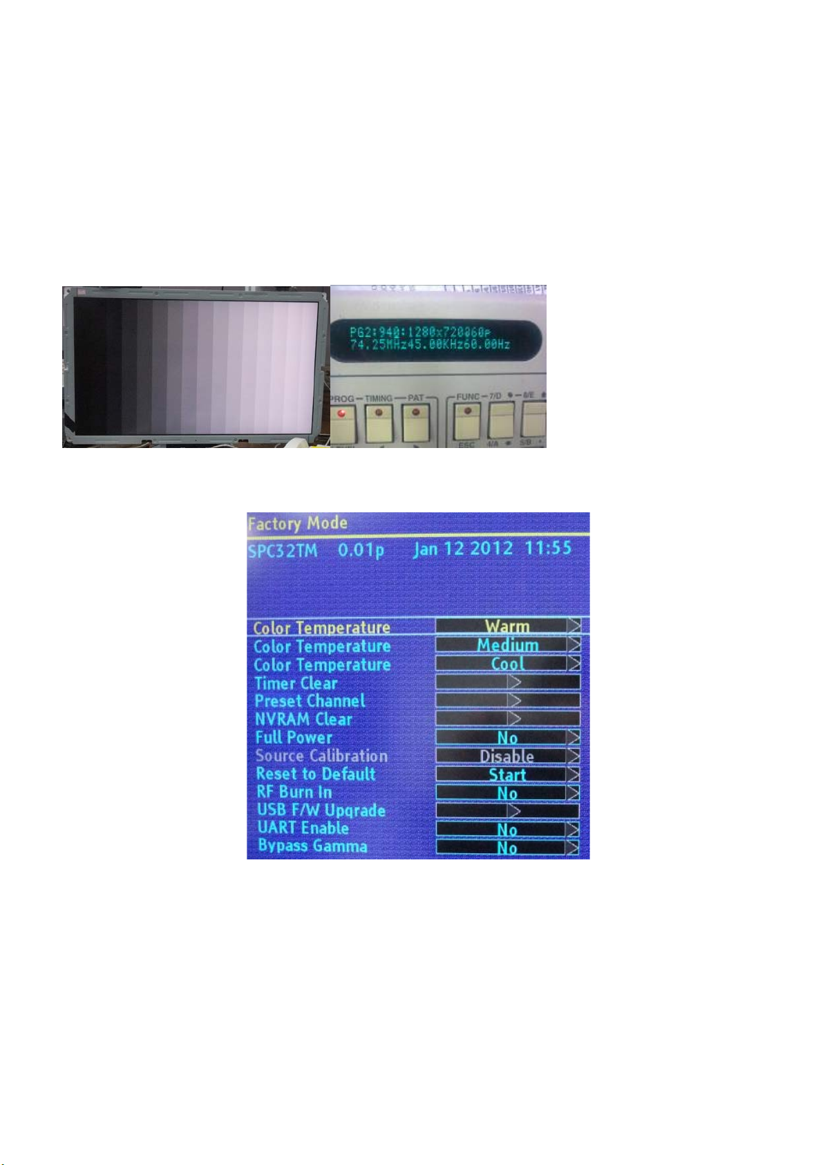
4-1. Source Calibration
4-1.1. Set the signal generator to input sources Component on LCD-TV; ASTRO-859 signal setting to NTSC-M
(PG2 mode Timing 924 and Pattern 984 SMPTE Color Bar.)
4-1.2. Entering into factory Mode: Press up or down key of remote control to select “Source Calibration”, Press
「OK」 key to enter the item.
-> Source calibration performed automatically when finished that will show OK.
Repeat step 2 to do VGA input sources,
ASTRO-859 signal setting to1024X768 60Hz. (PG2 mode: Timing 963 and Pattern 942 16step H-grayscale +
white border.)
7
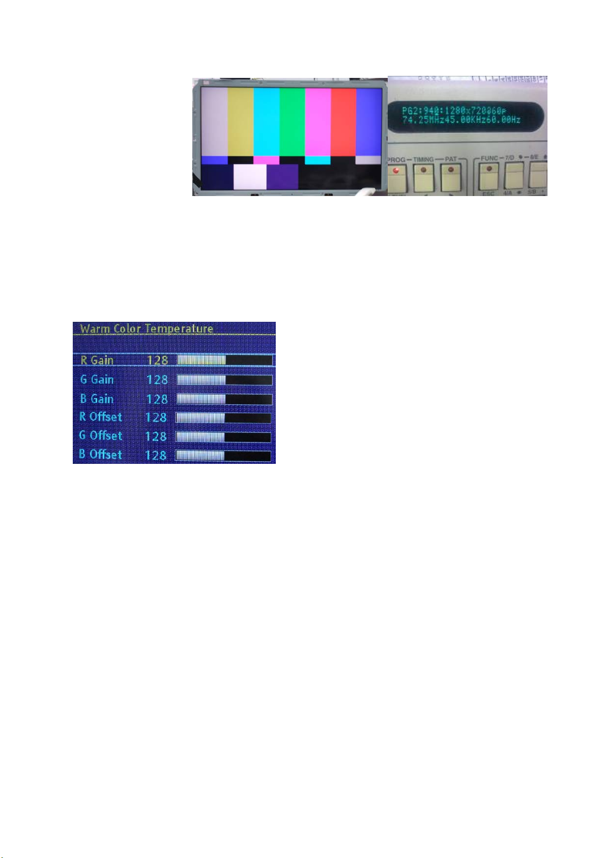
4-2. Color Temperature Adjustment & Che ck
4-2.1. Set the signal generator to RGB, 1024*768, 60HZ(ASTRO-859: PG1 856), Level: 77(30%) or
178(70%). Full white pattern. (RGB gain and offset all should not over 128,and one of RGB gain and offset
have to be setting on 110. )
4-2.2. Press up or down key of remote control to select “Cool”, Press 「ENTER」 key to enter the item.
RGAIN, GGAIN, BGAIN, ROFFSET, GOFFSET, BOFFSET, drive values are set for Warm, Normal
,
and Cool independently.
4-2.3. Select 「Warm」
Step 1.First Turning Gain parts of RGB.
(1) Warm spec.:
x= 0.318±0.005
y= 0.331±0.005
(2) If the x and y value are larger than specification,
Decrease R GAIN drive from default value.
Increase B GAIN drive from default value.
(3) If the x or y or both x and y value is/are smaller than specification.
Decrease B GAIN drive from default value
(4) According to a x and y value, please following adjustment of (4)-1 or (4)-2.
(4)-1 If x value is higher than spec
Decrease R GAIN drive from default value.
Increase B GAIN drive from default value.
(4)-2 If y value is higher than spec,
Decrease B GAIN drive from default value
Step 2.When finish Gain parts, then turning OFFSET parts
Select
(1) Medium spec.: (Same as the Gain session)
x= 0.289±0.005
y= 0.306±0.005
(2) If the x and y value are larger than specification,
Decrease R OFFSET drive from default value.
Increase B OFFSET drive from default value.
(3) If the x or y or both x and y value is/are smaller than specification.
「Normal」
8
Decrease B OFFSET drive from default value
(4) According to a x and y value, please following adjustment of (4)-1 or (4)-2.
(4)-1 If x value is higher than spec
Decrease R OFFSET drive from default value.
Increase B OFFSET drive from default value.
(4)-2 If y value is higher than spec,
Decrease B OFFSET drive from default value
Step 3.When finishing OFFSET parts, then recheck Gain parts .unitl Both of them meet the
target specification
Step 3. Than select
4-2.4. Exit Factory Mode:
After finish adjusting color temperature press [MENU] to exit factory mode.
「Cool」 using same way to adjust the setting.
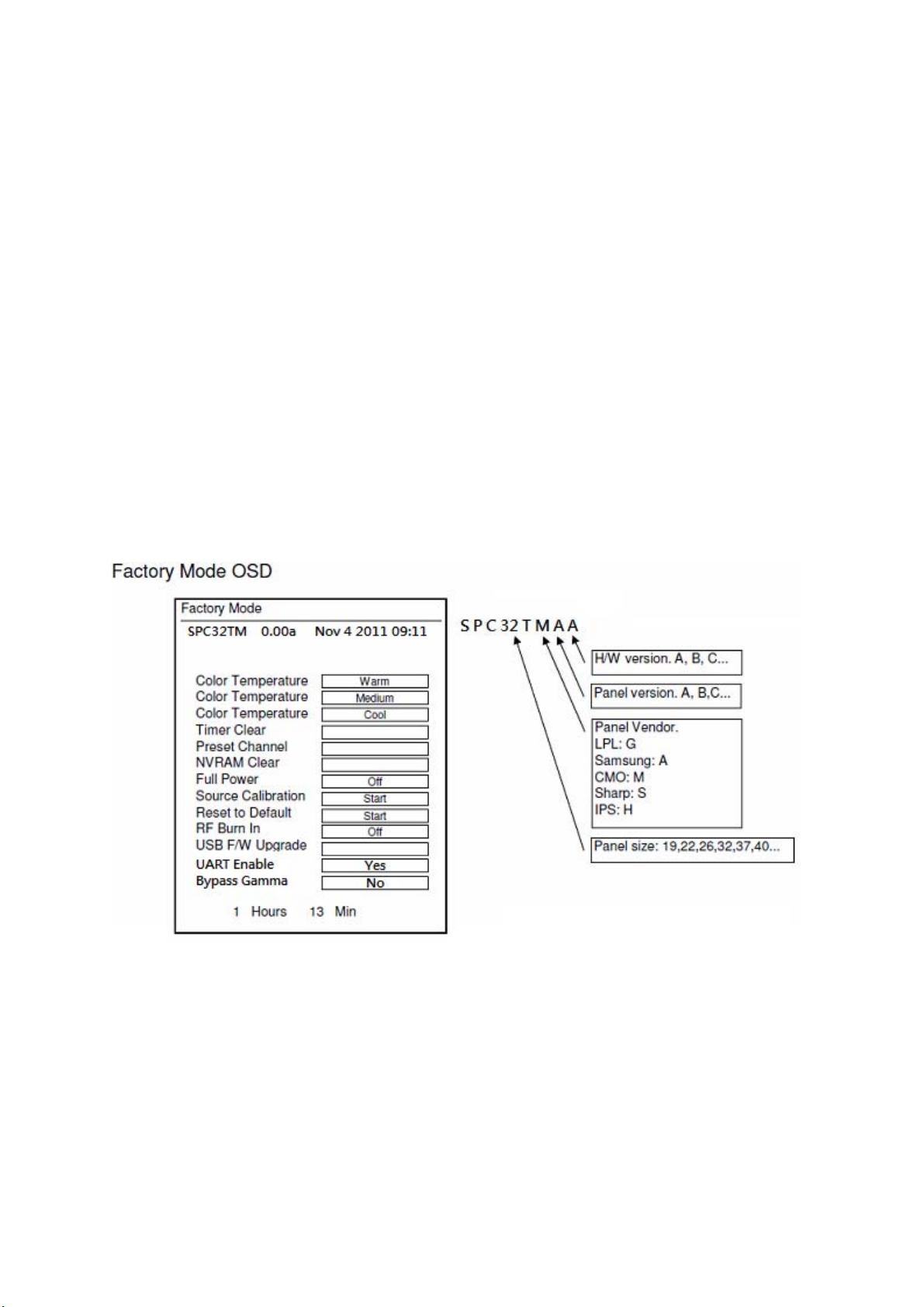
(5) Items of Factory menu
When in PC/ Component/ Video (Composite)/ ANT inputs then press the “Left -> Exit -> Enter” key of remote
control to enter factory mode..
During Factory menu, if “MENU” or “EXIT” key is pushed, system will exit factory mode.
Press up and down key can move high light item from Color Temperature -> Timer Clear -> Preset Channel>NVRAM Clear-> Full Power -> Source Calibration -> Reset to Default -> RF Burn In -> USB F/W Upgrade ->
UART Enable-> Bypass Gamma.
The Timer Clear, NVRAM Clear and Reset to Default items will have a check dialog “yes or no” to do or not.
Push “Enter” key can select high light item function. (Press left and right can adjust value)
Display panel Burn in Time on the bottom.
Display model name, firmware version and released date on top.
1) Factory Color Temp data edit
Press up or down key can select high light item function
Press enter key to enter the item.
-Color temp default preset No (Warm, Medium, Cool).
-R, G, B data for each preset
Press “Up” or “Down” key to select “R”, “G”, “B” item
Press “Left” or “Right” key to set the “R”, “G”, “B” value
Press “MENU” or “EXIT” item to exit to factory mode
2) Timer Clear
Reset the timer which records hours of LCD panel burn in
This item will have a check dialog “yes or no” to do or not.
- Time in factory mode: Time function shall be displayed automatically. Saving the total time of system
9

power on (LCD turn on), and count the time automatically. The timer is continuous and saved (per 10
minutes) forever, unless it will be reset by doing “Timer Clear”.
3) Preset channel
Load preset channel for production line. (Refer 4.4.4 Preset channel table).
4) NVRAM CLEAR
Initialize program’s default values to NVRAM for following adjustment items accuracy.
In factory mode it is the first and important step to make sure all values are default value and correct
- Reset settings: Gamma table, Channel table (Favorite channel, Channel label etc.), Model table
(H/V Position, Clock, Phase), Source dependent setting (Contrast, Brightness etc.), Common setting
(Volume, Language etc.), Parental Control (Rating, Password etc), Closed Caption.
To avoid a mistake initial process after factory setting is done. This item will have a check dialog “yes
or no” to do the initial or not.
Notice:
After this item is processed then the DUT needs to be powered off then AC powered off.
5) Full power
This is for power consumption testing.
To measure the maximum power consumption of TV set, we adjust the value of following items to
maximum.
- Video: Contrast maximum value, Brightness maximum value, Backlight maximum value.
- Audio: Volume maximum value, Bass default value, Treble default value.
Press enter key to turn on Full Power and OSD stay display until press enter key to recover from Full
Power
6) Source Calibration
Source Calibration (gain/offset) must be adjusted color by firmware automatic adjustment in PC,
Composite and Component input source.
This item will have a result dialog “OK” or “NG”.
7) Reset to Default
Reset all settings of OSD menu to default value.
- Reset settings: Channel table, Model table (H/V Position, Clock, Phase), Source dependent setting
(Contrast, Brightness etc.), Common setting (Volume, Language etc.), Parental Control (Rating,
Password etc), Closed Caption.
8) RF Burn In
Use “snow” pattern for burn in. Selected items are “On” and “Off”.
While turn on burn in mode, firmware will automatically turn off “Auto power off” function.
If there is no power supply suddenly, firmware will re-enter burn in mode automatically when power
supply is back
Pressed the “Power” key, firmware will automatically turn off burn in mode.
Burn in mode: Source is “ANT/Cable" and channel is NTSC channel 3.
9) USB F/W Upgrade
Upgrade firmware through USB.
10) UART Enable
Enable to communicate with Auto-Alignment system.
11) Bypass Gamma
For factory test value of gamma.
(6) Performance check
6-1 TV function
Connect RF to the center signal source, enter Channel menu → auto tuning, check if there are channels be
skipped, check if the picture and speaker are normal.
6-2 AV terminals
Input Video signal, check if the picture and sound are normal.
6-3 YPbPr terminal
Input YUV signal (VG859 signal generator), separately input the YUV signals listed in table4 and check if the
display and sound are normal at any situation (power on, channel switch and format convert, etc.)
Table4
YUV signal format
10
FREQ PERIOD
SYNC
POLARITY
PIXEL
CLOCK
Display
SYNC
WIDTH
BACK
PORCH
MODE
LINE(kHz)
FRAME
(Hz)
LINE (pixel)
FIELD
(lines)
LINE
FIELD
(MHz)
LINE (pixel)
FRAME
(lines)
LINE (pixel)
FRAME
(lines)
LINE (pixel)
FRAME
(lines)
15.734 1716 Negitive 27 1440 124 114
59.94Hz 720x480i
59.94Hz 720x480P
60Hz 1280x720P
60Hz 1920X1080i
60Hz 1920X1080P
59.94 525 Negitive 480 3 15
31,469 858 Negitive 27 720 62 60
59.94 525 Negitive 480 6 30
45 1650 Positive 74.25 1280 40 220
60 750 Positive 720 5 20
33.75 2200 Positive 74.25 1920 44 148
60 1125 Positive 1080 5 15
67.5 2200 Positive 148.5 1920 44 148
60 1125 Positive 1080 5 36
VGA terminal
6-4
Input VGA signal (VG848 signal generator), separately input the signals listed in table5 and check the display and
sound. If the image is deflection of the Horizontal and vertical, select Menu->Setup->Auto Adjust to perform autocorrect.
Table5 VGA signal format
FREQ PERIOD
POLARITY
SYNC
PIXEL
CLOCK
Display
SYNC
WIDTH
BACK
PORCH
Mode
LINE(kHz)
FRAME(Hz)
LINE (pixel)
FIELD(lines)
LINE
FIELD
(MHz)
LINE (pixel)
FRAME(lines)
LINE (pixel)
FRAME
(lines)
LINE (pixel)
FRAME
(lines)
VGA 60Hz 31.469 800 Negative 25.175 640 96 40
640x480 59.941 525 Negative 480 2 25
SVGA 60Hz 37.879 1056 Positive 40 800 128 88
800x600 60.317 628 Positive 600 4 23
XGA 60Hz 48.363 1344 Negative 65 1024 136 160
1024x768 60.004 806 Negative 768 6 29
WXGA 60Hz 47.776 1664 Negative 79.5 1280 128 192
1280x768 59.87 798 Positive 768 7 20
WXGA 60Hz 47.712 1792 Positive 85.5 1360 112 256
1360x768 60.015 795 Positive 768 6 18
6-5 HDMI terminal
Input HDMI signal (VG859 signal generator), separately input the signals listed in table6 and check the display and
sound (32 KHz, 44.1 KHz, 48 KHz) at any situation (power on, channel switch and format convert, etc.)
Table6
HDMI signal format
11
FREQ FREQ PERIOD
SYNC
POLARITY
PIXEL
CLOCK
Display
SYNC
WIDTH
BACK
PORCH
MODE
VGA 60Hz 31.469 800 Negitive 25.175 640 96 40
640x480 59.94 525 Negitive 480 2 25
SVGA 60Hz 37.879 1056 Positive 40 800 128 88
800x600 60.317 628 Positive 600 4 23
XGA 60Hz 48.363 1344 Negitive 65 1024 136 160
1024x768 60.004 806 Negitive 768 6 29
WXGA 60Hz 47.776 1664 Negitive 79.5 1280 128 192
1280x768 59.87 798 Positive 768 7 20
WXGA 60Hz 47.712 1792 Positive 85.5 1360 112 256
1360x768 60.015 795 Positive 768 6 18
59.94Hz 720x480i 15.734 1716 Negitive 27 1440 124 114
59.94 525 Negitive 480 3 15
59.94Hz 720x480P 31.469 858 Negitive 27 720 62 60
59.94 525 Negitive 480 6 30
60Hz 1280x720P 45 1650 Positive 74.25 1280 40 220
60 750 Positive 720 5 20
60Hz 1920X1080i 33.75 2200 Positive 74.25 1920 44 148
60 1125 Positive 1080 5 15
60Hz 1920X1080P 67.5 2200 Positive 148.5 1920 44 148
60 1125 Positive 1080 5 36
24Hz 1920x1080P 27 2750 Positive 74.25 1920 44 148
24 1125 Positive 1080 5 36
other functions check
6-6
a) Check the turn on/turn off timer, sleep timer, picture/sound mode, OSD, stereo and analog TV Teletext, etc.
LINE(kHz)
FRAME(Hz)
LINE (pixel)
FIELD(lines)
LINE
FIELD
(MHz)
LINE (pixel)
FRAME
(lines)
LINE (pixel)
FRAME
(lines)
LINE (pixel)
FRAME
(lines)
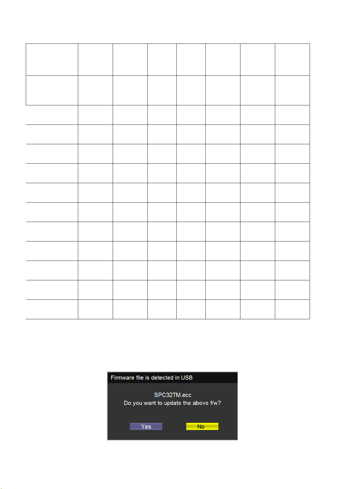
(7) Firmware update process
(1) Plug the USB with the firmware file named SPC32TM.ecc
(2) If system detect SPC32TM.ecc, USB upgrade message would appear automatically.
(3) Press Left key to select Yes, and then press OK key to start the upgrading.
12