

Panasonic TC-65DX900U Schematic
ORDER NO. MTV1605077CE
LED TV
Model No. TC-65DX900U
Chassis: LA65
Destination: U : USA
© Panasonic Corporation 2016.
TC-65DX900U
TABLE OF CONTENTS
PAG E PAG E
1 Safety Precautions -----------------------------------------------3
1.1. General Guidelines ----------------------------------------3
1.2. Touch-Current Check--------------------------------------3
2Warning--------------------------------------------------------------4
2.1. Prevention of Electrostatic Discharge (ESD)
to Electrostatically Sensitive (ES) Devices ----------4
2.2. About lead free solder (PbF) ----------------------------5
3 Service Navigation------------------------------------------------6
4 Specifications ------------------------------------------------------7
5 CS Maintenance Menu-------------------------------------------8
5.1. How to enter into CS Maintenance Menu ------------8
5.1.1. Purpose --------------------------------------------------8
5.1.2. Key command ------------------------------------------8
5.1.3. How to exit ----------------------------------------------8
5.2. Repack--------------------------------------------------------8
5.3. EDID Clock --------------------------------------------------9
5.4. USB HDD Drive Check -----------------------------------9
5.5. White Balance Adjustment----------------------------- 10
5.6. Version------------------------------------------------------ 11
5.6.1. How to access---------------------------------------- 11
5.7. Hotel mode------------------------------------------------- 12
5.7.1. Purpose ------------------------------------------------ 12
5.7.2. Access command to the Hotel mode setup
menu---------------------------------------------------- 12
5.7.3. To exit the Hotel mode setup menu------------- 12
5.7.4. Explain the Hotel mode setup menu------------ 12
5.8. Data Copy by USB Memory --------------------------- 13
5.8.1. Purpose ------------------------------------------------ 13
5.8.2. Preparation-------------------------------------------- 13
5.8.3. Data copy from TV set to USB Memory ------- 14
5.8.4. Data copy from USB Memory to TV set ------- 15
6 Troubleshooting Guide---------------------------------------- 16
6.1. Check of the IIC bus lines------------------------------ 16
6.1.1. How to access---------------------------------------- 16
6.1.2. Screen display --------------------------------------- 16
6.1.3. Check Point ------------------------------------------- 16
6.1.4. Exit ------------------------------------------------------ 16
6.2. Power LED Blinking timing chart --------------------- 17
6.3. LCD Panel test mode ----------------------------------- 17
7 Disassembly and Assembly Instructions --------------- 18
7.1. Panel Preparation ---------------------------------------- 18
7.2. VESA, Bottom Metal & Ornamnet-------------------- 19
7.3. PCB & AV Bracket Ass’y ------------------------------- 20
7.4. Screw Fixing -1 -------------------------------------------21
7.5. Screw Fixing -2 -------------------------------------------22
7.6. Fan Ass’y--------------------------------------------------- 23
7.7. Screw Fixing -3 -------------------------------------------24
7.8. Bottom Backcover Prep. ------------------------------- 25
7.9. Bottom & Backcover Ass’y----------------------------- 26
7.10. Handling SPEC ------------------------------------------- 27
8 Measurements and Adjustments -------------------------- 28
8.1. Voltage chart of A-board-------------------------------- 28
8.2. Voltage chart of P-board-------------------------------- 28
9 Block Diagram --------------------------------------------------- 29
10 Wiring Connection Diagram --------------------------------- 30
10.1. Wire Dressing -1------------------------------------------ 30
10.2. Wire Dressing -2------------------------------------------ 31
10.3. Wire Dressing -3------------------------------------------ 32
2
TC-65DX900U
1 Safety Precautions
1.1. General Guidelines
1. When servicing, observe the original lead dress. If a short circuit is found, replace all parts which have been overheated or
damaged by the short circuit.
2. After servicing, see to it that all the protective devices such as insulation barriers, insulation papers shields are properly
installed.
3. After servicing, make the following leakage current checks to prevent the customer from being exposed to shock hazards.
4. When conducting repairs and servicing, do not attempt to modify the equipment, its parts or its materials.
5. When wiring units (with cables, flexible cables or lead wires) are supplied as repair parts and only one wire or some of the
wires have been broken or disconnected, do not attempt to repair or re-wire the units. Replace the entire wiring unit instead.
6. When conducting repairs and servicing, do not twist the Fasten connectors but plug them straight in or unplug them straight
out.
1.2. Touch-Current Check
1. Plug the AC cord directly into the AC outlet. Do not use an isolation transformer for this check.
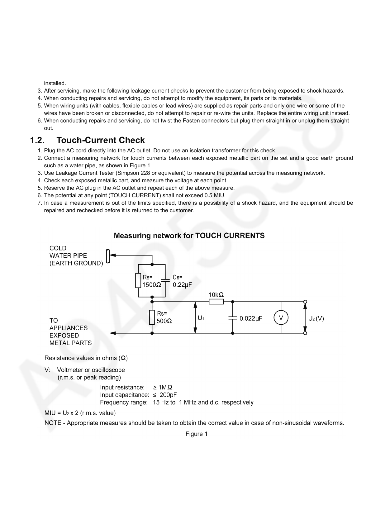
2. Connect a measuring network for touch currents between each exposed metallic part on the set and a good earth ground
such as a water pipe, as shown in Figure 1.
3. Use Leakage Current Tester (Simpson 228 or equivalent) to measure the potential across the measuring network.
4. Check each exposed metallic part, and measure the voltage at each point.
5. Reserve the AC plug in the AC outlet and repeat each of the above measure.
6. The potential at any point (TOUCH CURRENT) shall not exceed 0.5 MIU.
7. In case a measurement is out of the limits specified, there is a possibility of a shock hazard, and the equipment should be
repaired and rechecked before it is returned to the customer.
3
TC-65DX900U
2Warning
2.1. Prevention of Electrostatic Discharge (ESD) to Electrostatically Sensitive (ES) Devices
Some semiconductor (solid state) devices can be damaged easily by static electricity. Such components commonly are called
Electrostatically Sensitive (ES) Devices. Examples of typical ES devices are integrated circuits and some field-effect transistors and
semiconductor [chip] components. The following techniques should be used to help reduce the incidence of component damage
caused by electrostatic discharge (ESD).
1. Immediately before handling any semiconductor component or semiconductor-equipped assembly, drain off any ESD on your
body by touching a known earth ground. Alternatively, obtain and wear a commercially available discharging ESD wrist strap,
which should be removed for potential shock reasons prior to applying power to the unit under test.
2. After removing an electrical assembly equipped with ES devices, place the assembly on a conductive surface such as
aluminum foil, to prevent electrostatic charge buildup or exposure of the assembly.
3. Use only a grounded-tip soldering iron to solder or unsolder ES devices.
4. Use only an anti-static solder removal device. Some solder removal devices not classified as [anti-static (ESD protected)] can
generate electrical charge sufficient to damage ES devices.
5. Do not use freon-propelled chemicals. These can generate electrical charges sufficient to damage ES devices.
6. Do not remove a replacement ES device from its protective package until immediately before you are ready to install it. (Most
replacement ES devices are packaged with leads electrically shorted together by conductive foam, aluminum foil or
comparable conductive material).
7. Immediately before removing the protective material from the leads of a replacement ES device, touch the protective material
to the chassis or circuit assembly into which the device will be installed.
Caution
Be sure no power is applied to the chassis or circuit, and observe all other safety precautions.
8. Minimize bodily motions when handling unpackaged replacement ES devices. (Otherwise ham less motion such as the
brushing together of your clothes fabric or the lifting of your foot from a carpeted floor can generate static electricity (ESD)
sufficient to damage an ES device).
4
2.2. About lead free solder (PbF)
Note: Lead is listed as (Pb) in the periodic table of elements.
In the information below, Pb will refer to Lead solder, and PbF will refer to Lead Free Solder.
The Lead Free Solder used in our manufacturing process and discussed below is (Sn+Ag+Cu).
That is Tin (Sn), Silver (Ag) and Copper (Cu) although other types are available.
TC-65DX900U
This model uses Pb Free solder in it
suggest the use of Pb free solder as well, although Pb solder may be used.
PCBs manufactured using lead free solder will have the PbF within a leaf Symbol PbF stamped on the back of PCB.
Caution
• Pb free solder has a higher melting point than standard solder. Typically the melting point is 50 ~ 70 °F (30~40 °C) higher. Please
use a high temperature soldering iron and set it to 700 ± 20 °F (370 ± 10 °C).
• Pb free solder will tend to splash when heated too high (about 1100 °F or 600 °C).
If you must use Pb solder, please completely remove all of the Pb free solder on the pins or solder area before applying Pb
solder. If this is not practical, be sure to heat the Pb free solder until it melts, before applying Pb solder.
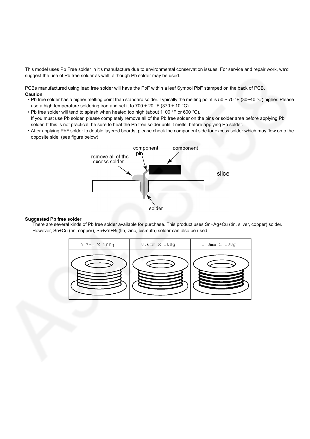
• After applying PbF solder to double layered boards, please check the component side for excess solder which may flow onto the
opposite side. (see figure below)
Suggested Pb free solder
There are several kinds of Pb free solder available for purchase. This product uses Sn+Ag+Cu (tin, silver, copper) solder.
However, Sn+Cu (tin, copper), Sn+Zn+Bi (tin, zinc, bismuth) solder can also be used.
's manufacture due to environmental conservation issues. For service and repair work, we'd
5
TC-65DX900U
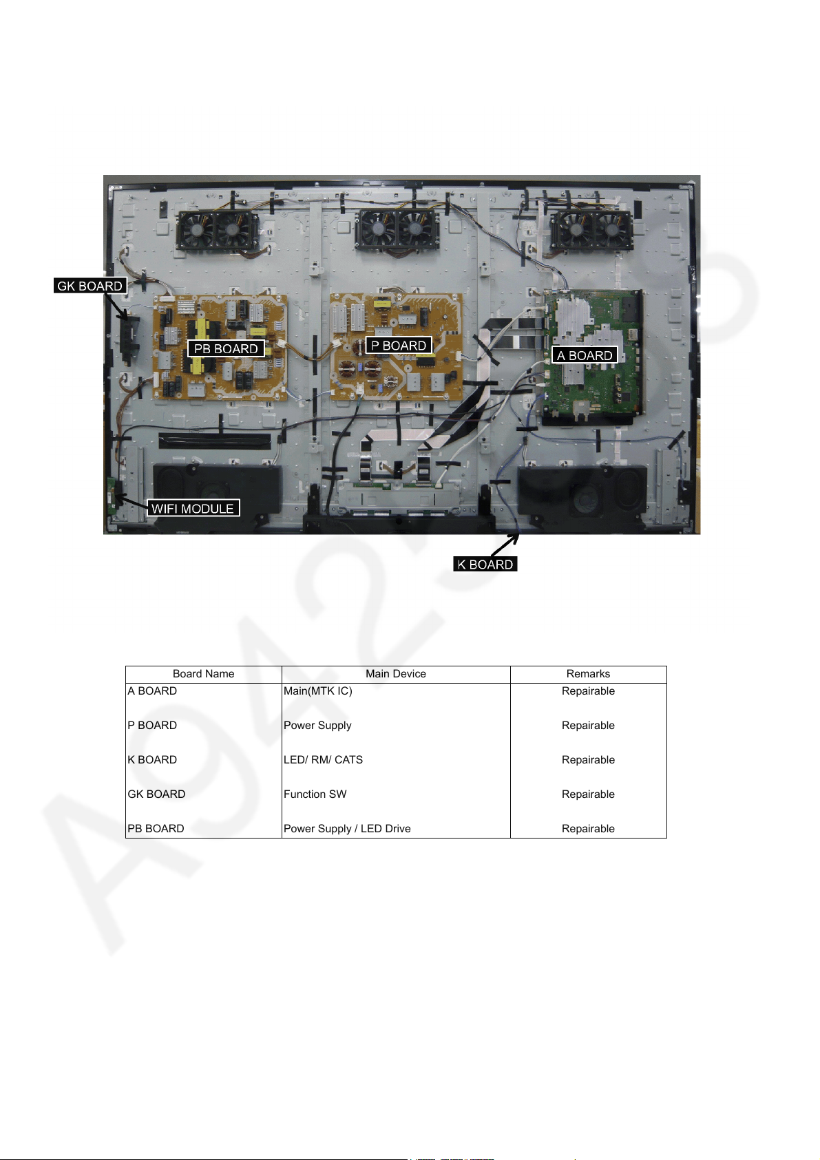
3 Service Navigation
Board Name Main Device Remarks
A BOARD Main(MTK IC) Repairable
P BOARD Power Supply Repairable
K BOARD LED/ RM/ CATS Repairable
GK BOARD Function SW Repairable
PB BOARD Power Supply / LED Drive Repairable
6
4 Specifications
Display Panel
Panel System LCD panel with LED backlight
Refresh Rate 120Hz
Screen size 65 inch class (64.5 inches measured diagonally)
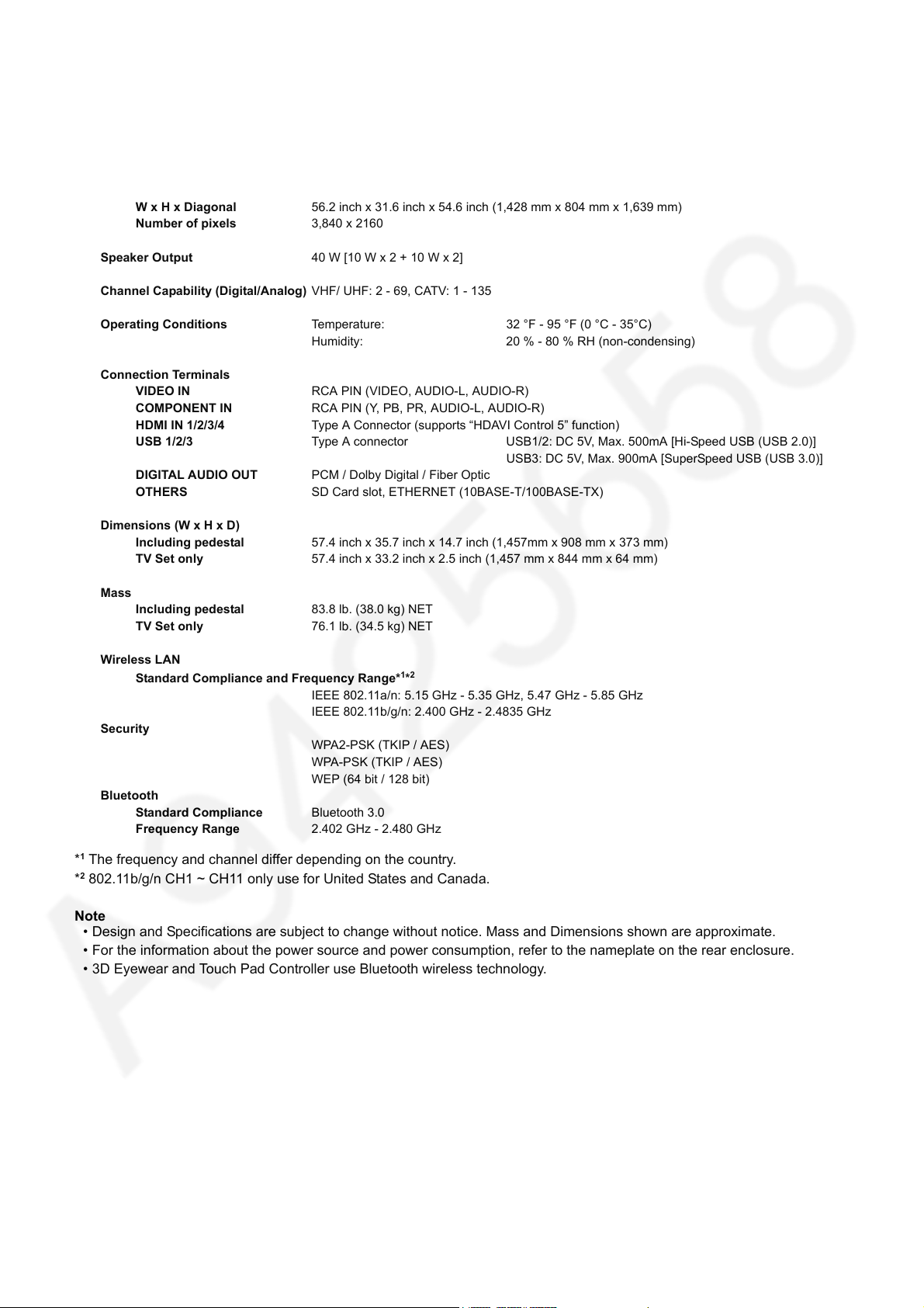
W x H x Diagonal 56.2 inch x 31.6 inch x 54.6 inch (1,428 mm x 804 mm x 1,639 mm)
Number of pixels 3,840 x 2160
Speaker Output 40 W [10 W x 2 + 10 W x 2]
Channel Capability (Digital/Analog) VHF/ UHF: 2 - 69, CATV: 1 - 135
Operating Conditions Temperature: 32 °F - 95 °F (0 °C - 35°C)
Humidity: 20 % - 80 % RH (non-condensing)
Connection Terminals
VIDEO IN RCA PIN (VIDEO, AUDIO-L, AUDIO-R)
COMPONENT IN RCA PIN (Y, PB, PR, AUDIO-L, AUDIO-R)
HDMI IN 1/2/3/4 Type A Connector (supports “HDAVI Control 5” function)
USB 1/2/3 Type A connector USB1/2: DC 5V, Max. 500mA [Hi-Speed USB (USB 2.0)]
USB3: DC 5V, Max. 900mA [SuperSpeed USB (USB 3.0)]
DIGITAL AUDIO OUT PCM / Dolby Digital / Fiber Optic
OTHERS SD Card slot, ETHERNET (10BASE-T/100BASE-TX)
TC-65DX900U
Dimensions (W x H x D)
Including pedestal 57.4 inch x 35.7 inch x 14.7 inch (1,457mm x 908 mm x 373 mm)
TV Set only 57.4 inch x 33.2 inch x 2.5 inch (1,457 mm x 844 mm x 64 mm)
Mass
Including pedestal 83.8 lb. (38.0 kg) NET
TV Set only 76.1 lb. (34.5 kg) NET
Wireless LAN
Standard Compliance and Frequency Range*
IEEE 802.11a/n: 5.15 GHz - 5.35 GHz, 5.47 GHz - 5.85 GHz
IEEE 802.11b/g/n: 2.400 GHz - 2.4835 GHz
Security
WPA2-PSK (TKIP / AES)
WPA-PSK (TKIP / AES)
WEP (64 bit / 128 bit)
Bluetooth
Standard Compliance Bluetooth 3.0
Frequency Range 2.402 GHz - 2.480 GHz
1*2
*1 The frequency and channel differ depending on the country.
2
*
802.11b/g/n CH1 ~ CH11 only use for United States and Canada.
Note
• Design and Specifications are subject to change without notice. Mass and Dimensions shown are approximate.
• For the information about the power source and power consumption, refer to the nameplate on the rear enclosure.
• 3D Eyewear and Touch Pad Controller use Bluetooth wireless technology.
7
TC-65DX900U
5 CS Maintenance Menu
5.1. How to enter into CS Maintenance Menu
5.1.1. Purpose
After exchange parts, check and adjust the contents of adjustment mode.
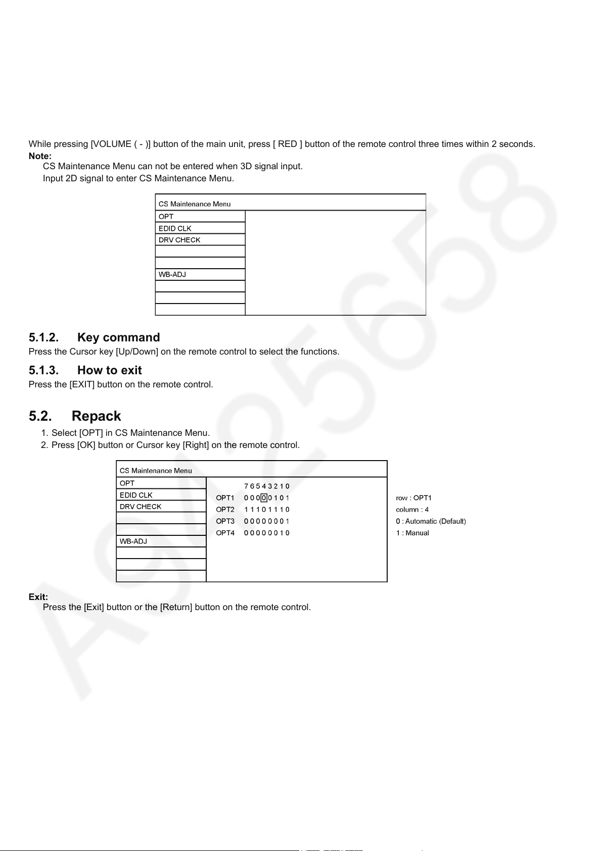
While pressing [VOLUME ( - )] button of the main unit, press [ RED ] button of the remote control three times within 2 seconds.
Note:
CS Maintenance Menu can not be entered when 3D signal input.
Input 2D signal to enter CS Maintenance Menu.
5.1.2. Key command
Press the Cursor key [Up/Down] on the remote control to select the functions.
5.1.3. How to exit
Press the [EXIT] button on the remote control.
5.2. Repack
1. Select [OPT] in CS Maintenance Menu.
2. Press [OK] button or Cursor key [Right] on the remote control.
Exit:
Press the [Exit] button or the [Return] button on the remote control.
8
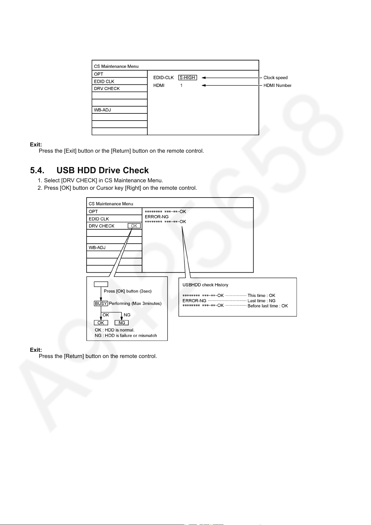
5.3. EDID Clock
1. Select [EDID CLK] in CS Maintenance Menu.
2. Press [OK] button or Cursor key [Right] on the remote control.
Exit:
Press the [Exit] button or the [Return] button on the remote control.
5.4. USB HDD Drive Check
1. Select [DRV CHECK] in CS Maintenance Menu.
2. Press [OK] button or Cursor key [Right] on the remote control.
TC-65DX900U
Exit:
Press the [Return] button on the remote control.
9
TC-65DX900U
5.5. White Balance Adjustment
After LCD PANEL or A-Board is replaced and repaired, perform [White balance adjustment] in case of necessity for test / check
([White balance adjustment] is not required basically).
1. Select [W/B ADJ] in CS Maintenance Menu.
2. Press [OK] button on the remote control.
Note for performing [White balance adjustment]
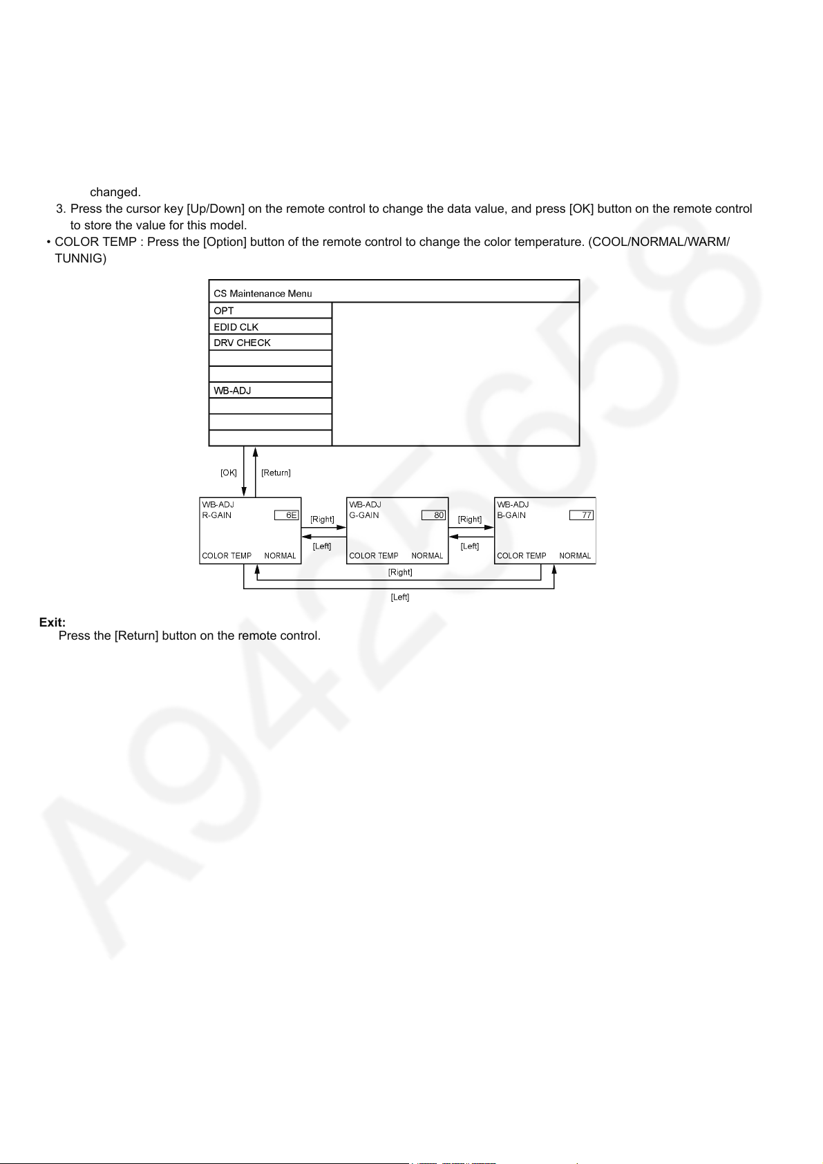
Make a note for the setting values before changing if the settings of [R-GAIN], [B-GAIN] and [G-GAIN] in [WB-ADJ] will be
changed.
3. Press the cursor key [Up/Down] on the remote control to change the data value, and press [OK] button on the remote control
to store the value for this model.
• COLOR TEMP : Press the [Option] button of the remote control to change the color temperature. (COOL/NORMAL/WARM/
TUNNIG)
Exit:
Press the [Return] button on the remote control.
10
5.6. Version
5.6.1. How to access
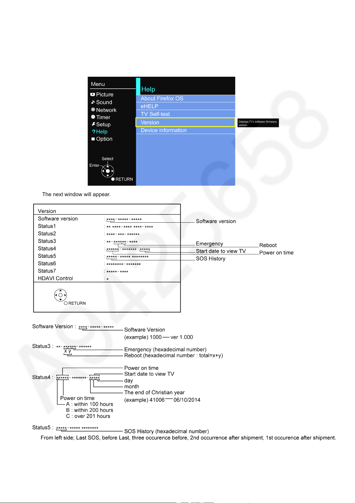
1. Display the [Main Menu] with [MENU] on the remote control.
2. Select [Help] with Cursor Key [Up] or [Down] on the remote control and press [OK] to access.
3. Select [Version] with cursor Key [Up] or [Down] on the remote control and press [OK] to access.
TC-65DX900U
The next window will appear.
11
TC-65DX900U
5.7. Hotel mode
5.7.1. Purpose
Restrict a function for hotels.
5.7.2. Access command to the Hotel mode setup menu
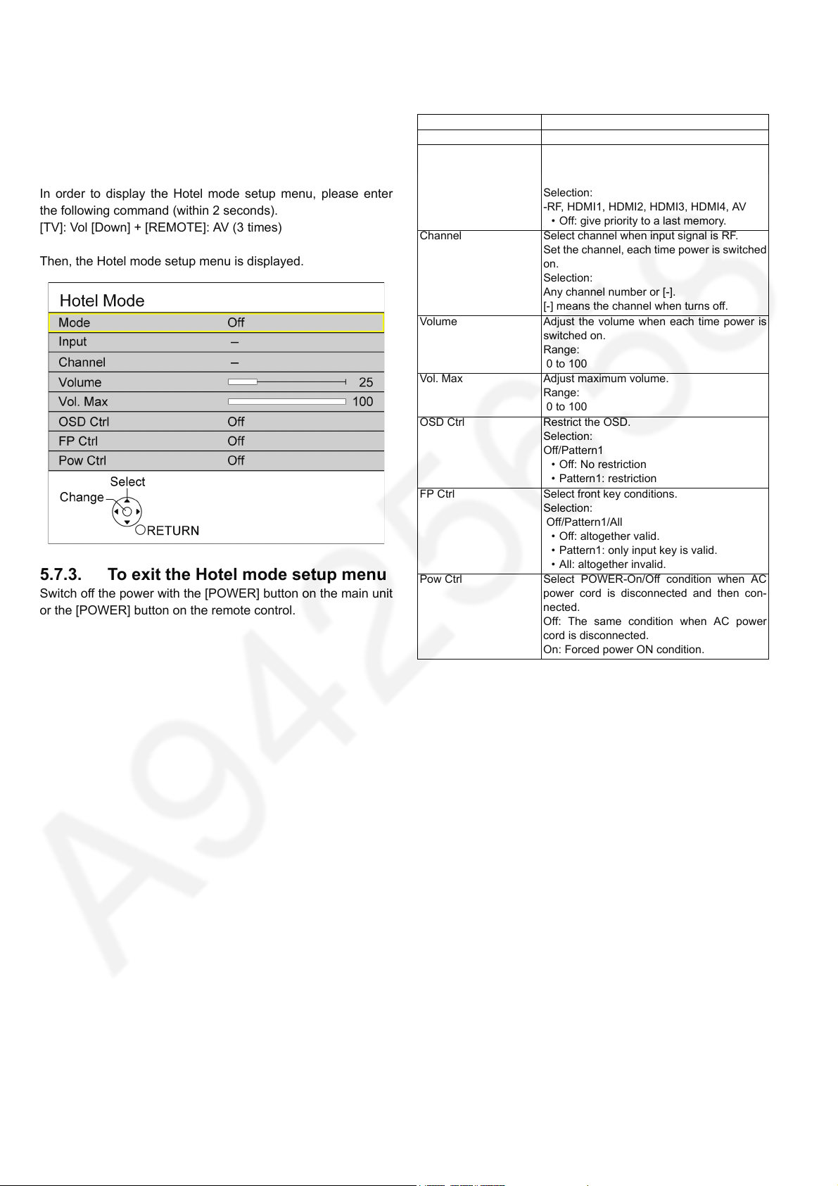
In order to display the Hotel mode setup menu, please enter
the following command (within 2 seconds).
[TV]: Vol [Down] + [REMOTE]: AV (3 times)
Then, the Hotel mode setup menu is displayed.
5.7.3. To exit the Hotel mode setup menu
Switch off the power with the [POWER] button on the main unit
or the [POWER] button on the remote control.
5.7.4. Explain the Hotel mode setup menu
Item Function
Mode Select hotel mode On/Off
Input Select input signal modes.
Set the input, when each time power is
switched on.
Selection:
-RF, HDMI1, HDMI2, HDMI3, HDMI4, AV
• Off: give priority to a last memory.
Channel Select channel when input signal is RF.
Set the channel, each time power is switched
on.
Selection:
Any channel number or [-].
[-] means the channel when turns off.
Volume Adjust the volume when each time power is
switched on.
Range:
0 to 100
Vol. Max Adjust maximum volume.
Range:
0 to 100
OSD Ctrl Restrict the OSD.
Selection:
Off/Pattern1
• Off: No restriction
• Pattern1: restriction
FP Ctrl Select front key conditions.
Selection:
Off/Pattern1/All
• Off: altogether valid.
• Pattern1: only input key is valid.
• All: altogether invalid.
Pow Ctrl Select POWER-On/Off condition when AC
power cord is disconnected and then con-
nected.
Off: The same condition when AC power
cord is disconnected.
On: Forced power ON condition.
12
TC-65DX900U
5.8. Data Copy by USB Memory
Note:
SD card can not be used for Data Copy.
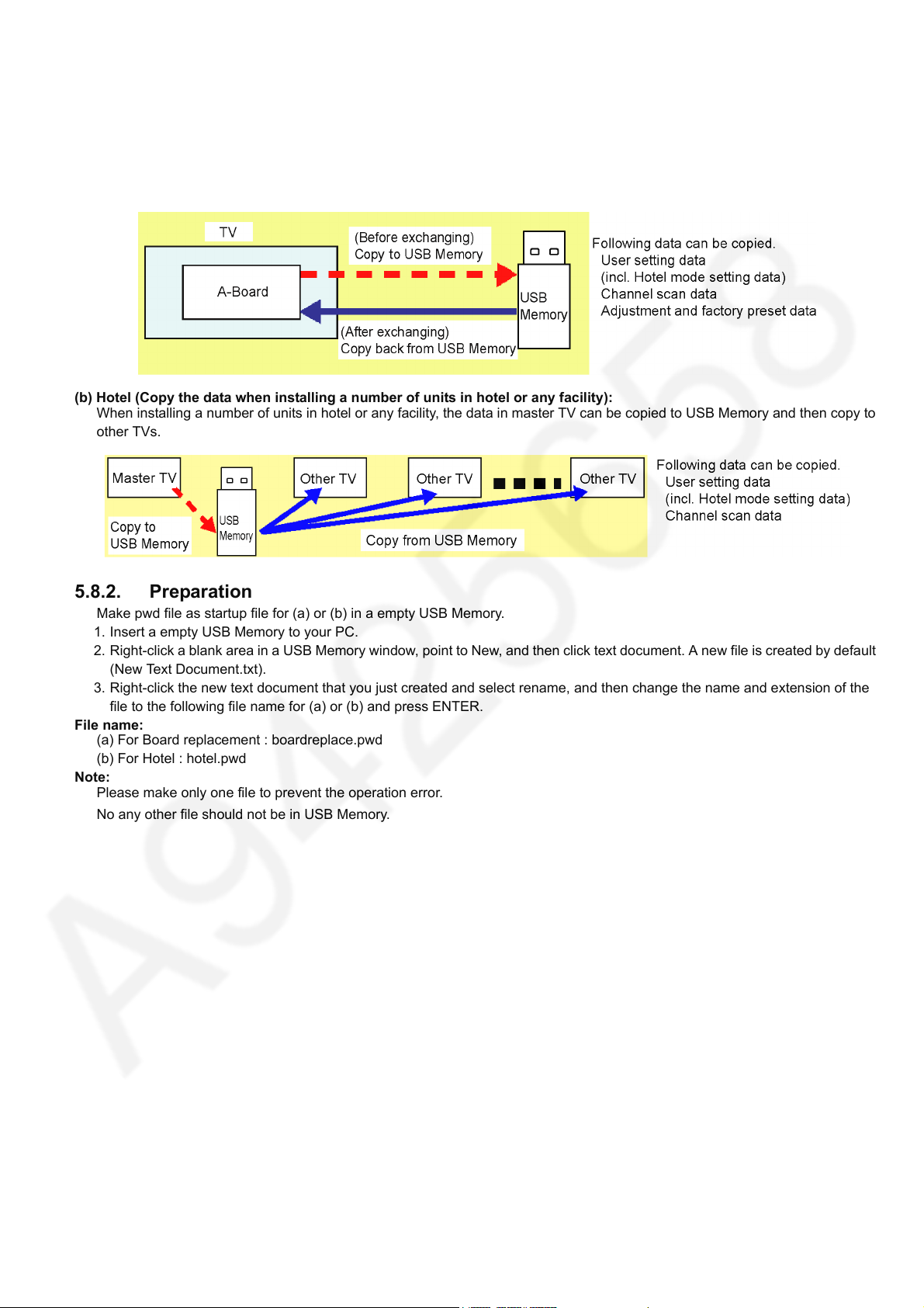
5.8.1. Purpose
(a) Board replacement (Copy the data when exchanging A-board):
When exchanging A-board, the data in original A-board can be copied to USB Memory and then copy to new A-board.
(b) Hotel (Copy the data when installing a number of units in hotel or any facility):
When installing a number of units in hotel or any facility, the data in master TV can be copied to USB Memory and then copy to
other TVs.
5.8.2. Preparation
Make pwd file as startup file for (a) or (b) in a empty USB Memory.
1. Insert a empty USB Memory to your PC.
2. Right-click a blank area in a USB Memory window, point to New, and then click text document. A new file is created by default
(New Text Document.txt).
3. Right-click the new text document that you just created and select rename, and then change the name and extension of the
file to the following file name for (a) or (b) and press ENTER.
File name:
(a) For Board replacement : boardreplace.pwd
(b) For Hotel : hotel.pwd
Note:
Please make only one file to prevent the operation error.
No any other file should not be in USB Memory.
13
TC-65DX900U
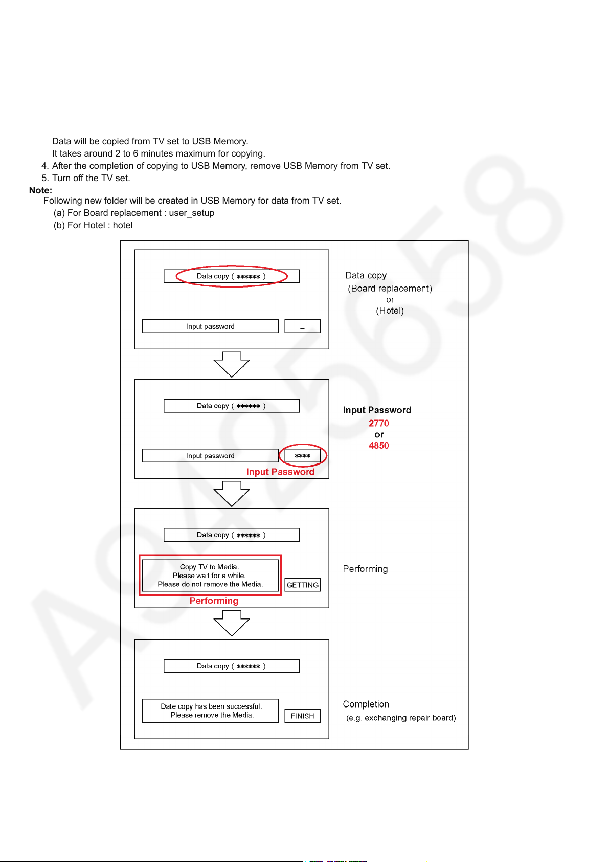
5.8.3. Data copy from TV set to USB Memory
1. Turn on the TV set.
2. Insert USB Memory with a startup file (pwd file) to USB terminal.
On-screen Display will be appeared according to the startup file automatically.
3. Input a following password for (a) or (b) by using remote control.
(a) For Board replacement : 2770
(b) For Hotel : 4850
Data will be copied from TV set to USB Memory.
It takes around 2 to 6 minutes maximum for copying.
4. After the completion of copying to USB Memory, remove USB Memory from TV set.
5. Turn off the TV set.
Note:
Following new folder will be created in USB Memory for data from TV set.
(a) For Board replacement : user_setup
(b) For Hotel : hotel
14
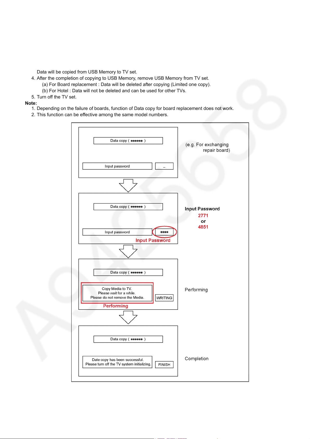
5.8.4. Data copy from USB Memory to TV set
1. Turn on the TV set.
2. Insert USB Memory with Data to USB terminal.
On-screen Display will be appeared according to the Data folder automatically.
3. Input a following password for (a) or (b) by using remote control.
(a) For Board replacement : 2771
(b) For Hotel : 4851
Data will be copied from USB Memory to TV set.
4. After the completion of copying to USB Memory, remove USB Memory from TV set.
(a) For Board replacement : Data will be deleted after copying (Limited one copy).
(b) For Hotel : Data will not be deleted and can be used for other TVs.
5. Turn off the TV set.
Note:
1. Depending on the failure of boards, function of Data copy for board replacement does not work.
2. This function can be effective among the same model numbers.
TC-65DX900U
15
TC-65DX900U
6 Troubleshooting Guide
Use the self-check function to test the unit.
1. Checking the IIC bus lines
2. Power LED Blinking timing
6.1. Check of the IIC bus lines
6.1.1. How to access
6.1.1.1. Self-check indication only:
Produce TV reception screen, and while pressing [VOLUME ( - )] button on the main unit, press [BLUE] button on the remote
control for more than 3 seconds.
6.1.1.2. Self-check indication and forced to factory shipment setting:
Produce TV reception screen, and while pressing [VOLUME ( - )] button on the main unit, press [MENU] button on the remote
control for more than 3 seconds.
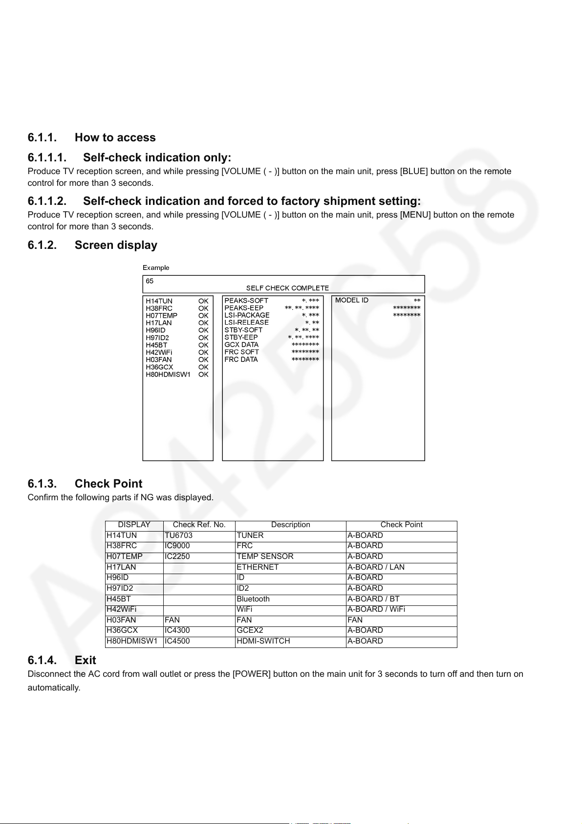
6.1.2. Screen display
6.1.3. Check Point
Confirm the following parts if NG was displayed.
DISPLAY Check Ref. No. Description Check Point
H14TUN TU6703 TUNER A-BOARD
H38FRC IC9000 FRC A-BOARD
H07TEMP IC2250 TEMP SENSOR A-BOARD
H17LAN ETHERNET A-BOARD / LAN
H96ID ID A-BOARD
H97ID2 ID2 A-BOARD
H45BT Bluetooth A-BOARD / BT
H42WiFi WiFi A-BOARD / WiFi
H03FAN FAN FAN FAN
H36GCX IC4300 GCEX2 A-BOARD
H80HDMISW1 IC4500 HDMI-SWITCH A-BOARD
6.1.4. Exit
Disconnect the AC cord from wall outlet or press the [POWER] button on the main unit for 3 seconds to turn off and then turn on
automatically.
16
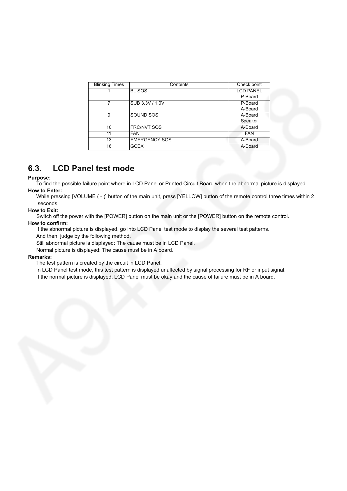
6.2. Power LED Blinking timing chart
1. Subject
Information of LED Flashing timing chart.
2. Contents
When an abnormality has occurred the unit, the protection circuit operates and reset to the stand by mode. At this time, the
defective block can be identified by the number of blinks of the Power LED on the front panel of the unit.
Blinking Times Contents Check point
1 BL SOS LCD PANEL
P-Board
7 SUB 3.3V / 1.0V P-Board
A-Board
9 SOUND SOS A-Board
Speaker
10 FRC/NVT SOS A-Board
11 FAN FAN
13 EMERGENCY SOS A-Board
16 GCEX A-Board
6.3. LCD Panel test mode
Purpose:
To find the possible failure point where in LCD Panel or Printed Circuit Board when the abnormal picture is displayed.
How to Enter:
While pressing [VOLUME ( - )] button of the main unit, press [YELLOW] button of the remote control three times within 2
seconds.
How to Exit:
Switch off the power with the [POWER] button on the main unit or the [POWER] button on the remote control.
How to confirm:
If the abnormal picture is displayed, go into LCD Panel test mode to display the several test patterns.
And then, judge by the following method.
Still abnormal picture is displayed: The cause must be in LCD Panel.
Normal picture is displayed: The cause must be in A board.
Remarks:
The test pattern is created by the circuit in LCD Panel.
In LCD Panel test mode, this test pattern is displayed unaffected by signal processing for RF or input signal.
If the normal picture is displayed, LCD Panel must be okay and the cause of failure must be in A board.
TC-65DX900U
17
TC-65DX900U
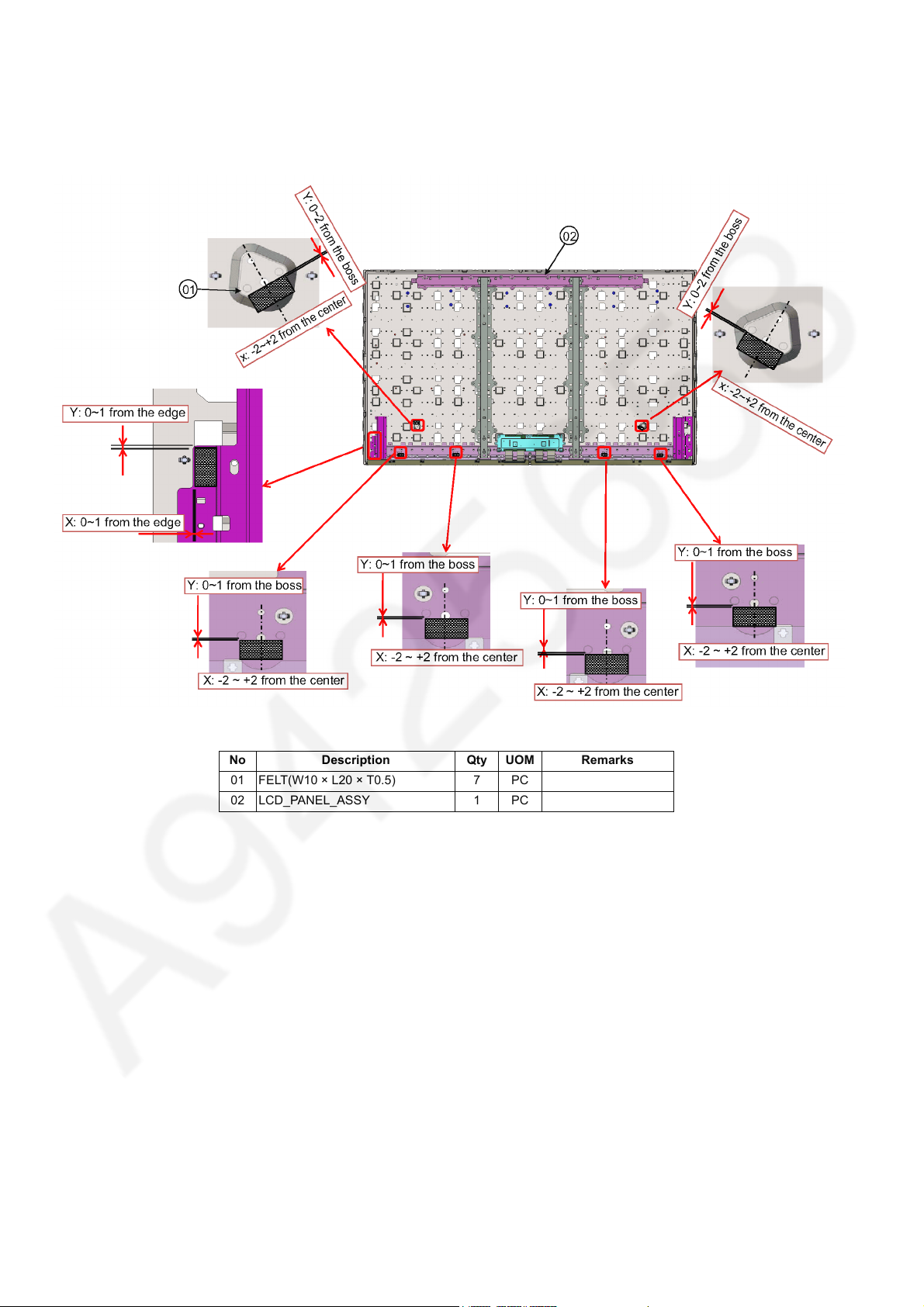
7 Disassembly and Assembly Instructions
7.1. Panel Preparation
1. Fix follow diagram.
No Description Qty UOM Remarks
01 FELT(W10 × L20 × T0.5) 7 PC
02 LCD_PANEL_ASSY 1 PC
18
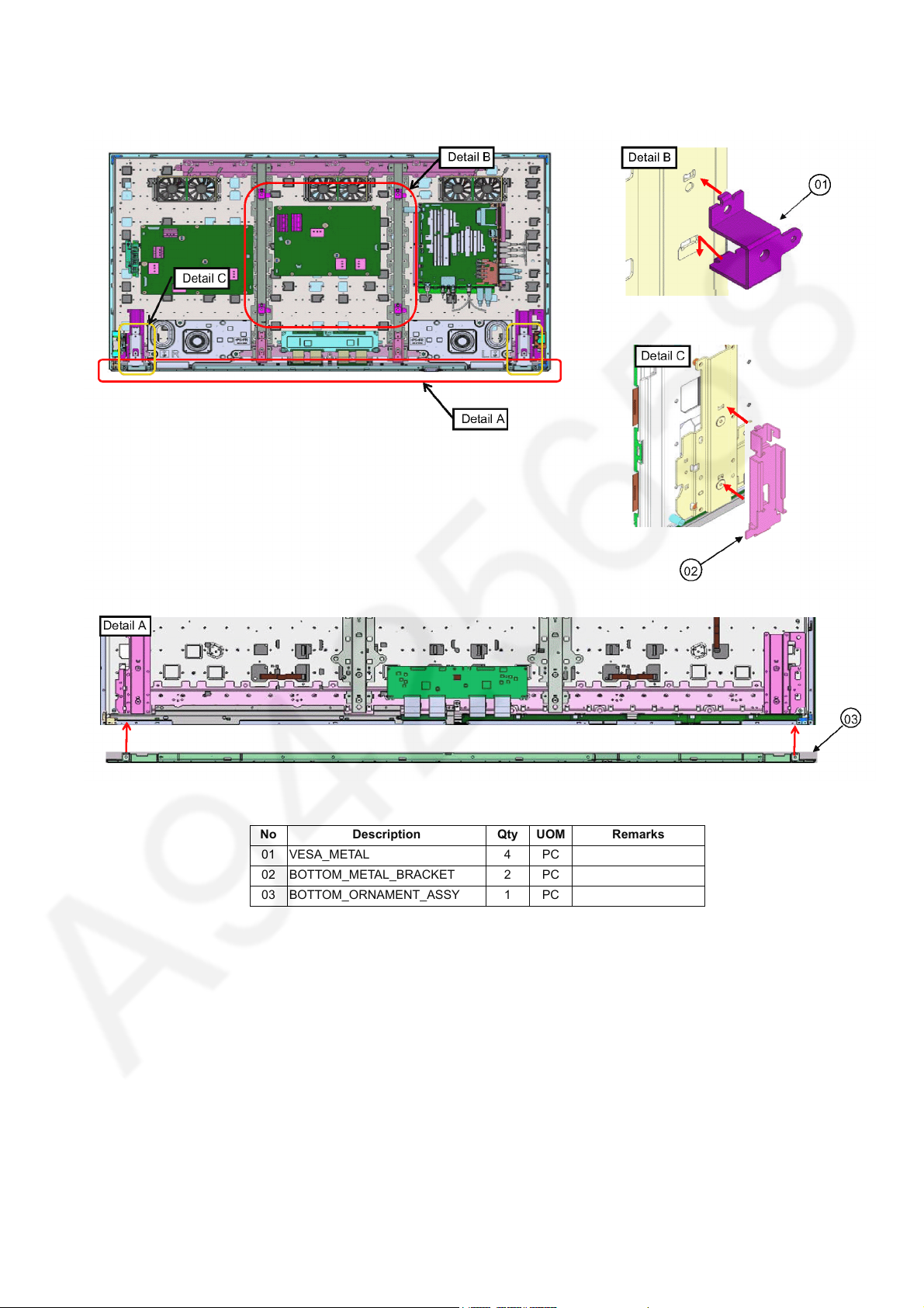
7.2. VESA, Bottom Metal & Ornamnet
1. Fix follow diagram.
TC-65DX900U
No Description Qty UOM Remarks
01 VESA_METAL 4 PC
02 BOTTOM_METAL_BRACKET 2 PC
03 BOTTOM_ORNAMENT_ASSY 1 PC
19
TC-65DX900U
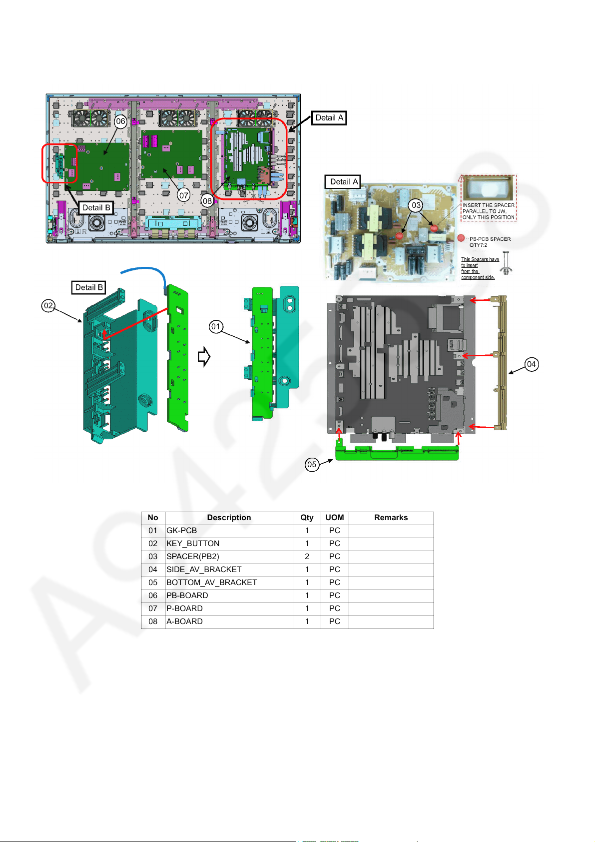
7.3. PCB & AV Bracket Ass’y
1. Fix follow diagram.
No Description Qty UOM Remarks
01 GK-PCB 1 PC
02 KEY_BUTTON 1 PC
03 SPACER(PB2) 2 PC
04 SIDE_AV_BRACKET 1 PC
05 BOTTOM_AV_BRACKET 1 PC
06 PB-BOARD 1 PC
07 P-BOARD 1 PC
08 A-BOARD 1 PC
20
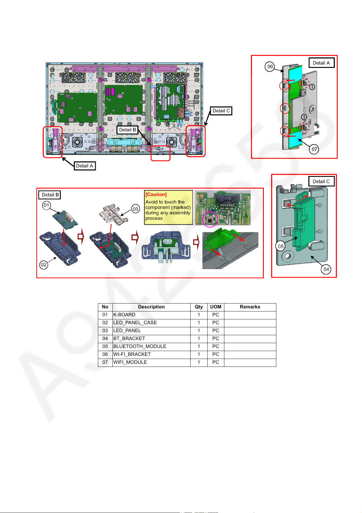
7.4. Screw Fixing -1
1. Fix follow diagram.
TC-65DX900U
No Description Qty UOM Remarks
01 K-BOARD 1 PC
02 LED_PANEL_CASE 1 PC
03 LED_PANEL 1 PC
04 BT_BRACKET 1 PC
05 BLUETOOTH_MODULE 1 PC
06 WI-FI_BRACKET 1 PC
07 WIFI_MODULE 1 PC
21
TC-65DX900U
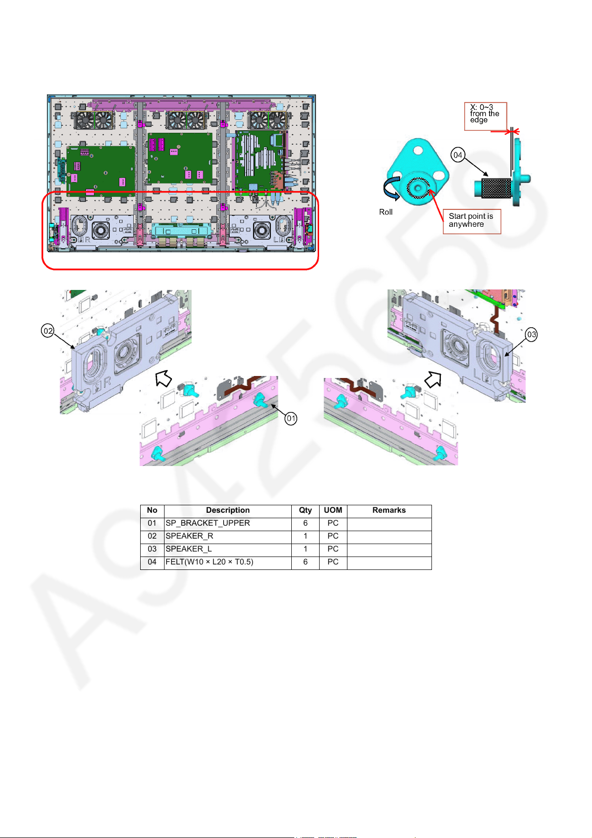
7.5. Screw Fixing -2
1. Fix follow diagram.
No Description Qty UOM Remarks
01 SP_BRACKET_UPPER 6 PC
02 SPEAKER_R 1 PC
03 SPEAKER_L 1 PC
04 FELT(W10 × L20 × T0.5) 6 PC
22
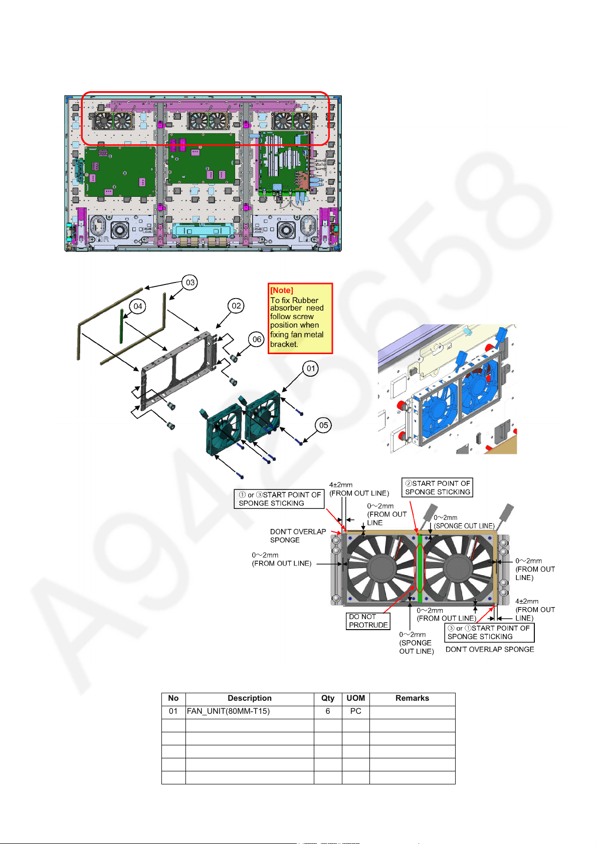
7.6. Fan Ass’y
1. Fix follow diagram.
TC-65DX900U
No Description Qty UOM Remarks
01 FAN_UNIT(80MM-T15) 6 PC
02 FAN_METAL_BRACKET 3 PC
03 FAN SPONGE 6 PC
04 FAN SPONGE 3 PC
05 SCREW 24 PC 4~6 kgf
06 RUBBER(ABSORBER) 12 PC
23
TC-65DX900U
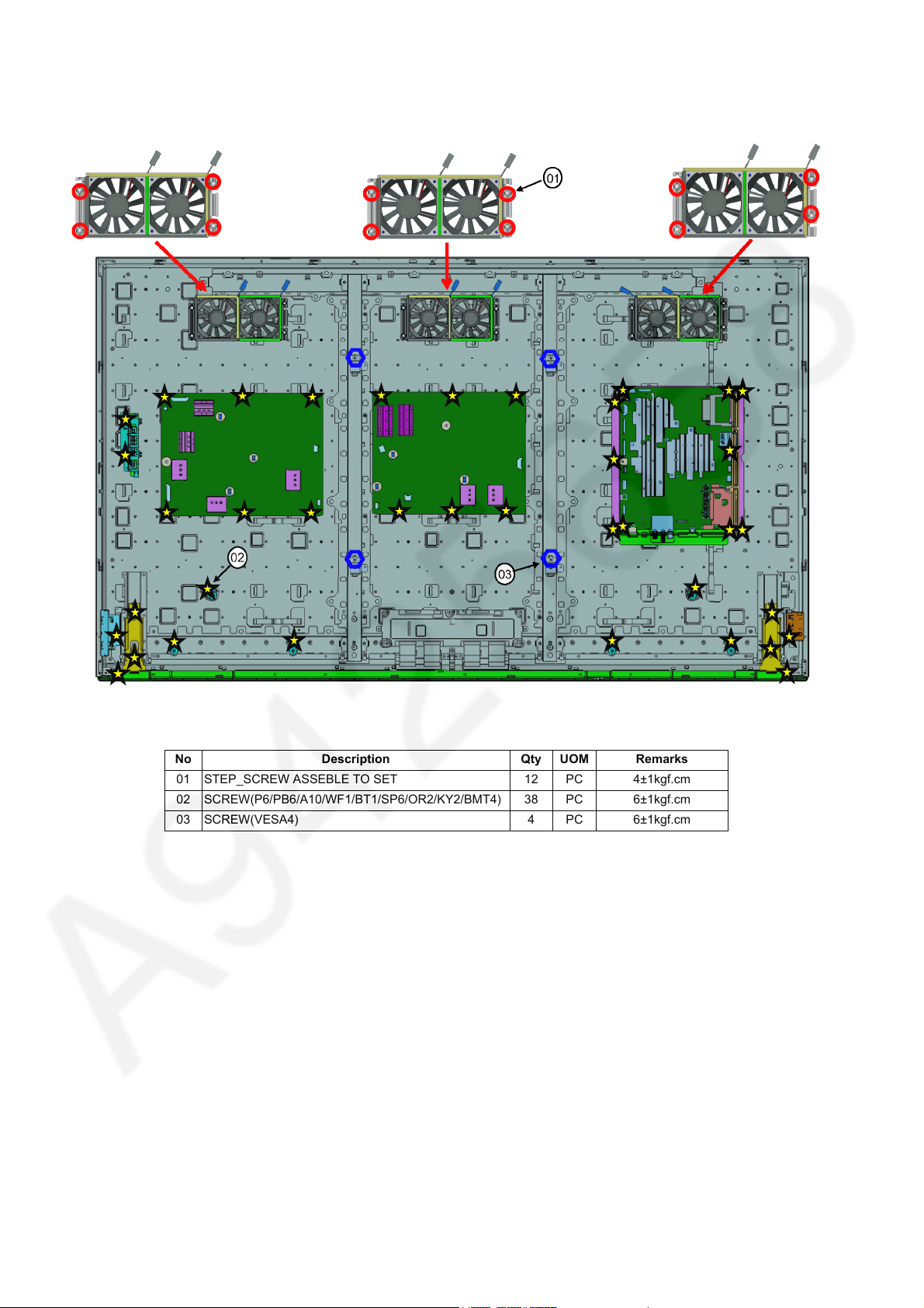
7.7. Screw Fixing -3
1. Fix follow diagram.
No Description Qty UOM Remarks
01 STEP_SCREW ASSEBLE TO SET 12 PC 4±1kgf.cm
02 SCREW(P6/PB6/A10/WF1/BT1/SP6/OR2/KY2/BMT4) 38 PC 6±1kgf.cm
03 SCREW(VESA4) 4 PC 6±1kgf.cm
24
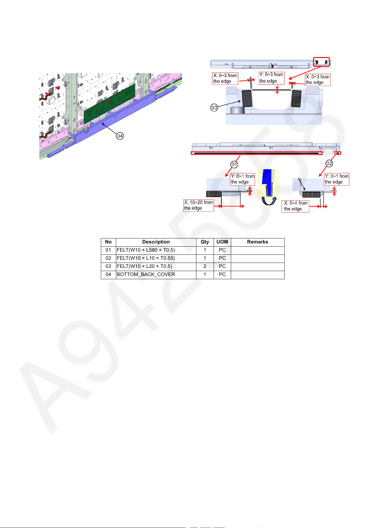
7.8. Bottom Backcover Prep.
1. Fix follow diagram.
TC-65DX900U
No Description Qty UOM Remarks
01 FELT(W10 × L580 × T0.5) 1 PC
02 FELT(W10 × L10 × T0.55) 1 PC
03 FELT(W10 × L20 × T0.5) 2 PC
04 BOTTOM_BACK_COVER 1 PC
25
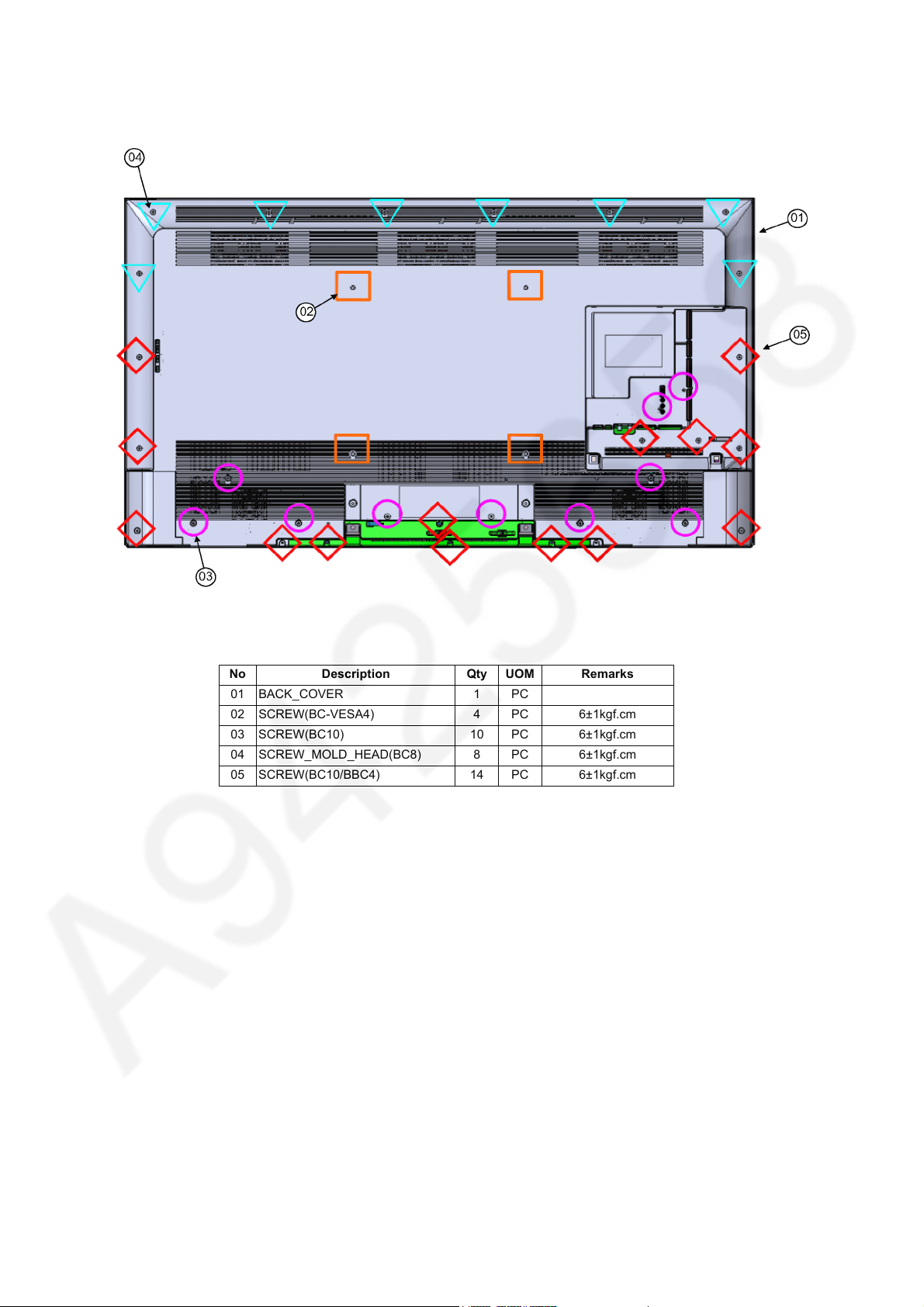
TC-65DX900U
7.9. Bottom & Backcover Ass’y
1. Fix follow diagram.
No Description Qty UOM Remarks
01 BACK_COVER 1 PC
02 SCREW(BC-VESA4) 4 PC 6±1kgf.cm
03 SCREW(BC10) 10 PC 6±1kgf.cm
04 SCREW_MOLD_HEAD(BC8) 8 PC 6±1kgf.cm
05 SCREW(BC10/BBC4) 14 PC 6±1kgf.cm
26
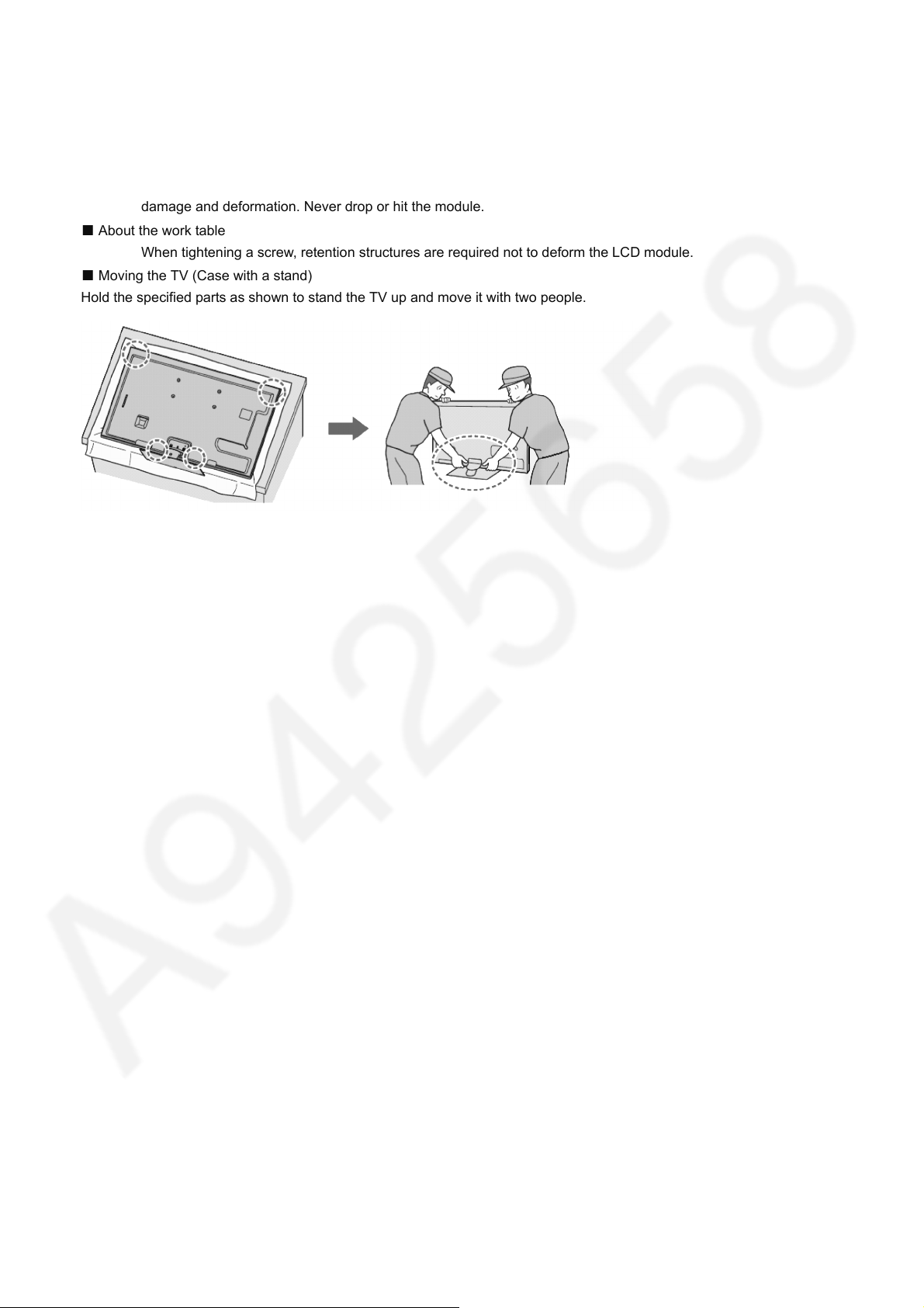
7.10. Handling SPEC
■ Moving the LCD module
The module should be handle by two people and hold on that top and bottom long side by both hands without module
warping. Never handle the module with keeping horizontal position when moving the module in order to avoid internal
damage and deformation. Never drop or hit the module.
■ About the work table
When tightening a screw, retention structures are required not to deform the LCD module.
■ Moving the TV (Case with a stand)
Hold the specified parts as shown to stand the TV up and move it with two people.
TC-65DX900U
27
TC-65DX900U
8 Measurements and Adjustments
8.1. Voltage chart of A-board
Set A-Board to a dummy set and check the satisfaction with the specified voltage as following table.
Checked Name Test Point Specification In/Out Target Board Suffix
PNL12V TP4059 12V ± 1.2V output ALL
USB5V TP5221 5.18V ± 0.25V output ALL
USB1 TP8701 5.0V ± 0.25V output ALL
USB2 TP8705 5.0V ± 0.25V output ALL
USB3 TP8711 5.0V ± 0.25V output ALL
USB-WiFi TP8718 5.14V ± 0.20V output ALL
SUB3.3V TP5201 3.33V ± 0.15V output ALL
HDMI1.1V TP4503 1.13V ± 0.06V output
HDMISW3.3V TP4514 3.35V ± 0.17V output ALL
SUB_AI_3.3V TP2206 3.3V ± 0.17V output ALL
STB_1.5V TP8101 1.52V ± 0.07V output ALL
SUB1.0V TP8100 1.02V +0.03V -0.05V output ALL
AVDD1.0V TP8102 1.06V ± 0.05V output ALL
NT2.5V TP9170 2.52V ± 0.12V output ALL
NT1.5V TP9160 1.25V ± 0.07V output ALL
NT1.1V TP9150 1.13V ± 0.06V output ALL
GE_1.1V TP4450 1.10V - 1.19V output
WOL3.3V/PHY3.3V TP8606 3.3V ± 0.17V output ALL
EU_TU_1.8V TP5704 1.84V ± 0.1V output ALL
SD3.3V TP8644 3.34V ± 0.17V output ALL
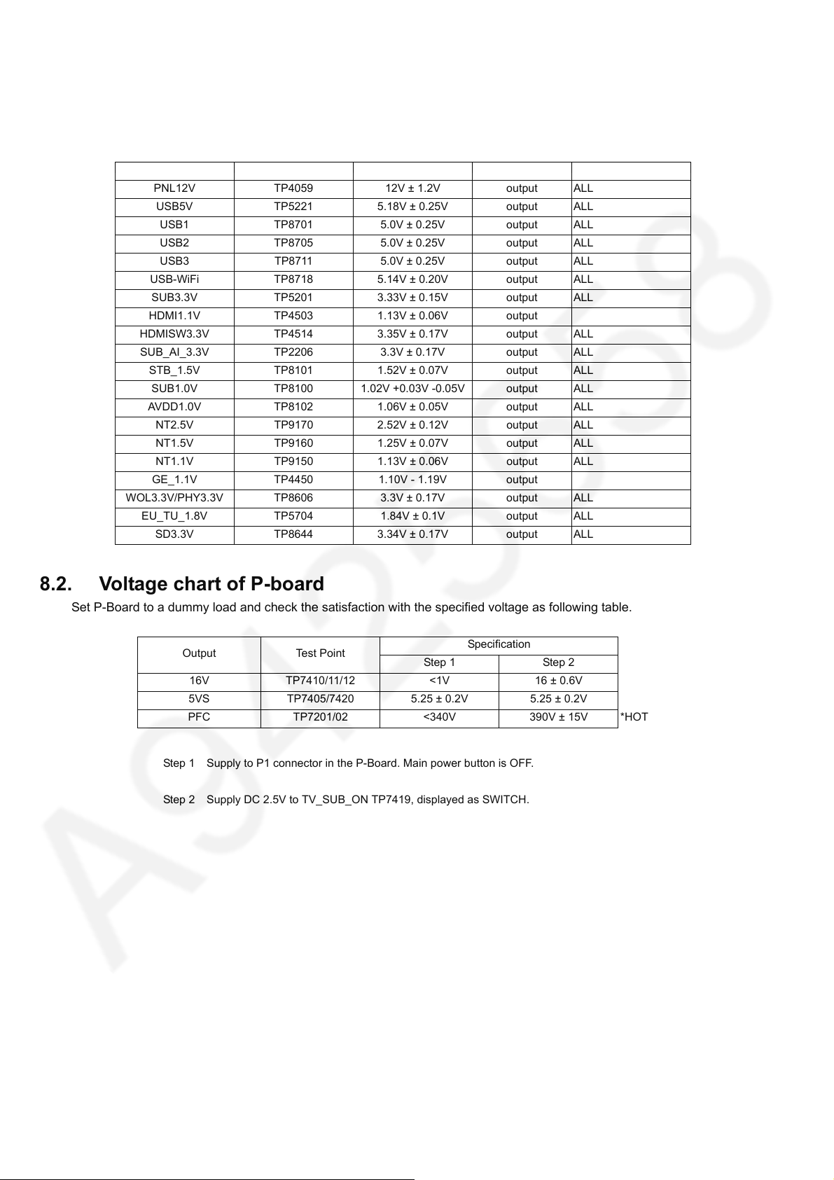
8.2. Voltage chart of P-board
Set P-Board to a dummy load and check the satisfaction with the specified voltage as following table.
Output Test Point
16V TP7410/11/12 <1V 16 ± 0.6V
5VS TP7405/7420 5.25 ± 0.2V 5.25 ± 0.2V
PFC TP7201/02 <340V 390V ± 15V *HOT
Step 1 Supply to P1 connector in the P-Board. Main power button is OFF.
Step 2 Supply DC 2.5V to TV_SUB_ON TP7419, displayed as SWITCH.
Step 1 Step 2
Specification
28
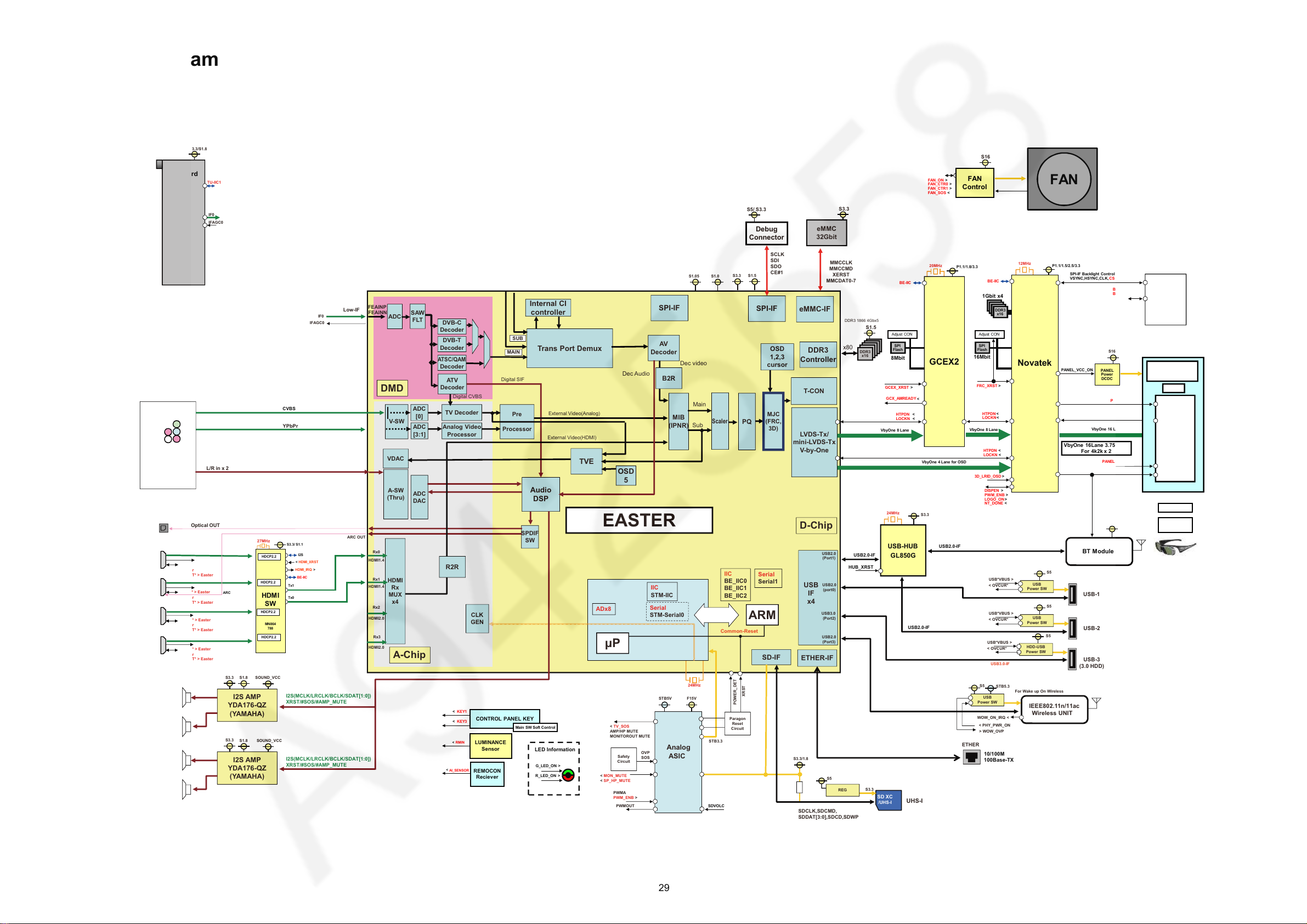
9 Block Diagram
S3.3
YPbPr
L/R in x 2
OPT
Analog AV
Y
Pb
Pr
R
L
Optical OUT
S5/ S3.3
S3.3
eMMC
32Gbit
Debug
Connector
A-SW
(Thru)
V-SW
HDMI
Rx
MUX
x4
ADC
[3:1]
Analog Video
Processor
ADC
DAC
ADC
Pre
Processor
A-Chip
SPDIF
SW
D-Chip
Trans Port Demux
DDR3
Controller
Audio
DSP
STB3.3
AV
Decoder
EASTER
Serial
Serial1
IIC
STM-IIC
Serial
STM-Serial0
24MHz
CLK
GEN
SOUND_VCC
LVD S-T x/
mini-LVDS-Tx
V-by-One
T-CON
S1.5
ATV
Decoder
DVB-C
Decoder
USB
IF
x4
ETHER-IF
FEAINP
FEAINN
Internal CI
controller
Low-IF
DMD
I2S(MCLK/LRCLK/BCLK/SDAT[1:0])
XRST/#SOS/#AMP_MUTE
I2S(MCLK/LRCLK/BCLK/SDAT[1:0])
XRST/#SOS/#AMP_MUTE
ADC
[0]
TV Decoder
SAW
FLT
Digital CVBS
DVB-T
Decoder
ATSC/QAM
Decoder
Digital SIF
MIB
(IPNR)
Main
Sub
OSD
1,2,3
cursor
External Video(Analog)
External Video(HDMI)
Dec video
x80
TVE
OSD
5
VDAC
PQ
MJC
(FRC,
3D)
Scaler
Dec Audio
ADx8
B2R
SPI-IF
SCLK
SDI
SDO
CE#1
S1.5
S3.3
S1.0
IIC
BE_IIC0
BE_IIC1
BE_IIC2
S1.8
I2S AMP
YDA176-QZ
(YAMAHA)
IFAGC0
IF0
P
ARM
XRST
POWER_DET
< TV_SOS
AMP/HP MUTE
MONITOROUT MUTE
F15V
STB5V
Analog
ASIC
OVP
SOS
Safety
Circuit
< MON_MUTE
< SP_HP_MUTE
PWMA
PWM_ENB >
PWMOUT
Common-Reset
Paragon
Reset
Circuit
USB2.0
(Port1)
USB2.0
(port0)
USB3.0
(Port2)
USB2.0
(Port3)
DDR3
x16
DDR3 1866 4Gbx5
MMCCLK
MMCCMD
XERST
MMCDAT0-7
eMMC-IF
S1.05
MAIN
SUB
SPI-IF
Rx0
Rx1
Rx2
Rx3
HPD* < Easter
HDMI_5V_DET* > Easter
DDC* > Easter
HPD* < Easter
HDMI_5V_DET* > Easter
HPD* < Easter
HDMI_5V_DET* > Easter
DDC* > Easter
HDMI1
HDMI2
HDMI3
R2R
HDMI1.4
HDMI1.4
HDMI2.0
HDMI2.0
ARC OUT
Lch:10W
Rch:10W
ETHER
STB5.3
S5
IEEE802.11n/11ac
Wireless UNIT
USB
Power SW
S5
HDD-USB
Power SW
USB3.0-IF
For Wake up On Wireless
WOW_ON_IRQ <
< PHY_PWR_ON
> WOW_OVP
USB*VBUS >
< OVCUR*
USB
Power SW
S5
USB*VBUS >
< OVCUR*
USB
Power SW
S5
USB*VBUS >
< OVCUR*
USB-1
USB-2
USB-3
(3.0 HDD)
HPD* < Easter
HDMI_5V_DET* > Easter
DDC* > Easter
HDMI4
24MHz
S3.3
BT Module
S3.3
USB-HUB
GL850G
USB2.0-IF
USB2.0-IF
HUB_XRST
CVBS
SD-IF
SDCLK,SDCMD,
SDDAT[3:0],SDCD,SDWP
SD XC
/UHS-I
S3.3
REG
S5
S3.3/1.8
UHS-I
HDMI2.0
HDCP2.2
HDMI2.0
HDCP2.2
HDMI2.0
HDCP2.2
HDMI2.0
HDCP2.2
27MHz
S3.3
SOUND_VCC
S1.8
I2S AMP
YDA176-QZ
(YAMAHA)
Lch:10W
Rch:10W
S16
20MHz
12MHz
10/100M
100Base-TX
USB2.0-IF
ARC
LED Information
G_LED_ON >
R_LED_ON >
< KEY3
< KEY1
CONTROL PANEL KEY
REMOCON
Reciever
LUMINANCE
Sensor
AI_SENSOR
<
RMIN
<
Main SW Soft Control
I2S
S3.3/ S1.1
HDMI
SW
MN864
788
<
HDMI_XRST
BE-IIC
<
HDMI_IRQ
Tx1
Tx0
HDCP2.2
HDCP2.2
HDCP2.2
HDCP2.2
SDVOLC
FAN
Control
FAN
FAN_ON >
FAN_CTR0 >
FAN_CTR1 >
FAN_SOS <
Bluetooth Glass
INX
Activ e 3D
Panel
P1.1/1.8/3.3
SPI
Flash
Adjust CON
8Mbit
SPI
Flash
Adjust CON
16Mbit
P1.1/1.5/2.5/3.3
Panel
T-CON
VbyOne 16 Lane
PANEL
Power
DCDC
PANEL_VCC_ON
P12
Novatek
LED Driver
BL_ON >
BL_SOS <
SPI-IF Bac klight Cont rol
VSYNC,HSYNC,CLK,CS[0:3]
,DO,DI
VbyOne 16Lane 3.75Gbps
For 4k2k x 2
PNL_3D_ON >
HTPDN <
LOCKN <
DDR3DDR3
x16
DDR3
x16
1Gbit x4
512 area
X:32 Y:16
3D_LRID
>
DDR3
x16
GCEX2
VbyOne 8 Lane
HTPDN <
LOCKN <
BE-IIC
BE-IIC
DISPEN >
PWM_ENB >
LOGO_ON>
NT_DONE <
VbyOne 8 Lane
HTPDN <
<
LOCKN <
PANEL_T EST_ ON >
3D_LRID_OSD >
VbyOne 4 Lane forOSD
HTPDN <
LOCKN <
GCX_AMREADY
FRC_XRST >
GCEX_XRST >
INX
S16
S3.3/S1.8
TUNER
IFAGC0
F
TU-IIC1
IF0
On Board
TC-65DX900U
29
TC-65DX900U
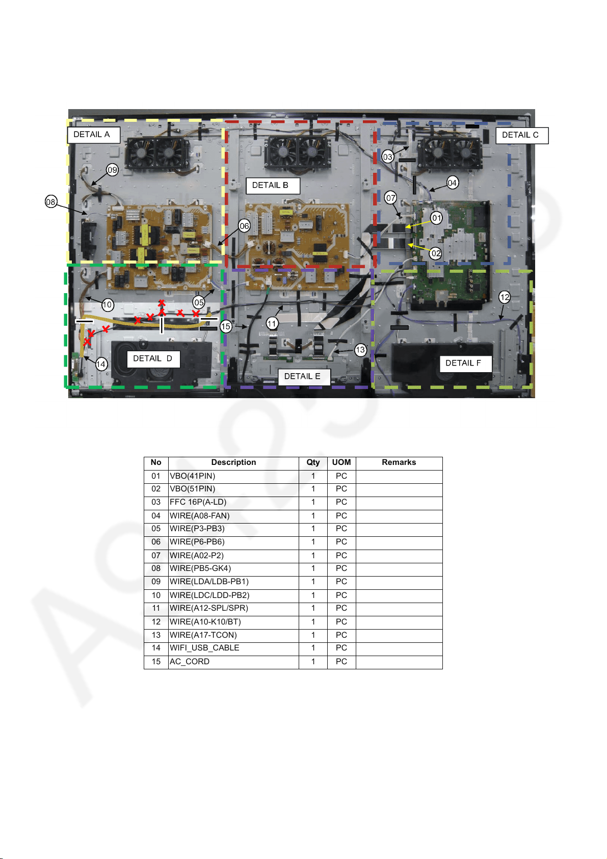
10 Wiring Connection Diagram
10.1. Wire Dressing -1
No Description Qty UOM Remarks
01 VBO(41PIN) 1 PC
02 VBO(51PIN) 1 PC
03 FFC 16P(A-LD) 1 PC
04 WIRE(A08-FAN) 1 PC
05 WIRE(P3-PB3) 1 PC
06 WIRE(P6-PB6) 1 PC
07 WIRE(A02-P2) 1 PC
08 WIRE(PB5-GK4) 1 PC
09 WIRE(LDA/LDB-PB1) 1 PC
10 WIRE(LDC/LDD-PB2) 1 PC
11 WIRE(A12-SPL/SPR) 1 PC
12 WIRE(A10-K10/BT) 1 PC
13 WIRE(A17-TCON) 1 PC
14 WIFI_USB_CABLE 1 PC
15 AC_CORD 1 PC
30
 Loading...