

Panasonic TC-58DX800C, TC-65DX800 Schematic
ORDER NO. PMX1608011CE
SERVICE MANUAL
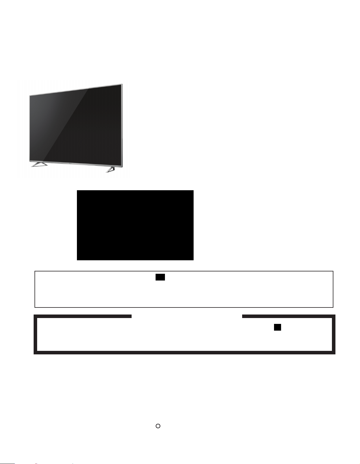
Class 4K Ultra HD TV
WARNING
This service information is designed for experienced repair technicians only and is not designed for use by the general public.
It does not contain warnings or cautions to advise non-technical individuals of potential dangers in attempting to service a product.
Products powered by electricity should be serviced and repaired only by experienced professional technicians. Any attempt to service or
repair the product or products dealt with in this service information by anyone else could result in serious injury or death.
Model No.
TC-58DX800C UHDTV
TC-65DX800C UHDTV
Chassis: LA67
Destination: Canada
© Copyright all rights reserved 2016 by Panasonic de México,
S.A. de C.V.
R
There are special components used in this equipment which are important for safety. These parts are market by in the schematic
diagrams, Circuit board diagrams, Exploded Views and replacement parts list. it is essential that these critical parts should be replaced with
manufacturer’s specified parts to prevent shock, fire or other hazards. Do not modify the original design without permission of manufacturer.
IMPORTANT SAFETY NOTICE
58”
65”

TABLE OF CONTENTS
1 Safety Precautions -----------------------------------------------3
1.1.General Guidelines------------------------------------------3
1.1.1. Leakage Current Cold Check--------------------------3
1.1.2.
Leakage Current Hot Check (See Figure 1.)
2 Warning --------------------------------------------------------------4
2.1.Prevention of Electrostatic Discharge (ESD)
to Electrostatically Sensitive (ES) Devices-----------4
2.2.About lead free solder (PbF)------------------------------4
---------3
PAGE
3 Service mode
3.1. Purpose ------------------------------------------------------5
How to enter into Service Mode
3.5. Edid clock
4.4. USB HDD check
5 White balance adjustment
5.1 System information
5.2 Data copy to USB
6 Troubleshooting Guide
7 Hotel Mode--------------------------------------------------------- 11
8 Measurements and Adjustments --------------------------- 12
9 Specifications ------------------------------------------------------13
10 Block Diagram
11 Disassembly and Assembly Instructions--------------- 15
11 TC-65DX800C Model -------------------------------------------15
12 TC-58DX800C Model--------------------------------------------20
13 Replacement Parts List -------------------------------------- 25
13.1TC-58DX800C A Board ---------------------------------- 26
13.2. TC-65DX800C A Board -------------------------------- 39
13.3. TC-58DX800C P Board -------------------------------- 52
13.4. TC-65DX800C P Board -------------------------- 58
13.5. TC-58DX800C K Board -------------------------------- 62
13.6.TC-65DX800C K Board --------------------------------- 63
13.7. TC-65DX800C GK Board ------------------------------ 64
13.8. TC-65DX800C PB PCB ---------------------------- 65
13.9. TC-58DX800C Mechanical --------------------------- 70
13.9. TC-65DX800C Mechanical --------------------------- 71
--------------------------------------------
----------------------6
------------------------------------
------------------------------------
---------------------------------
-----------------------------------
-----------------------------------
------------------------------------
------------------------------------------------------
5
6
6
6
7
8
10
14
14 PCBs Layout
14.1 Layout A Board --------------------------------------------73
14.2 Layout P Board TC-58DX800C -------------------- 75
14.4 Layout P & GK Board TC-65DX800C -------------- 76
14.6 Layout K PCB ----------------------------------------- 78
14.7. Layout PB PCB TC-65DX800C ------------------- 87
15 Electric diagrams
Main A Board ---------------------------------------------------- 82
Remote sensor board K Board ------------------------------ 107
Power board P Board TC-58DX800C --------------------- 108
Power board P Board TC-65DX800C --------------------- 109
PCB GK TC-65DX800C ----------------------------------- 110
PCB PB TC-65DX800C ------------------------------------ 111
-------------------------------------
---------------------------------
73
80
2
1 Safety Precautions
1.1. General Guidelines
1. When servicing, observe the original lead dress. If a short circuit is found, replace all parts which have been overheated or
damaged by the short circuit.
2. After servicing, see to it that all the protective devices such as insulation barriers, insulation papers shields are properly
installed.
3. After servicing, make the following leakage current checks to prevent the customer from being exposed to shock hazards.
4. When conducting repairs and servicing, do not attempt to modify the equipment, its parts or its materials.
5. When wiring units (with cables, flexible cables or lead wires) are supplied as repair parts and only one wire or some of the
wires have been broken or disconnected, do not attempt to repair or re-wire the units. Replace the entire wiring unit instead.
6. When conducting repairs and servicing, do not twist the Faston connectors but plug them straight in or unplug them straight
out.
1.1.1. Leakage Current Cold Check
1. Unplug the AC cord and connect a jumper between the
two prongs on the plug.
2. Measure the resistance value, with an ohmmeter,
between the jumpered AC plug and each exposed
metallic cabinet part on the equipment such as
screwheads, connectors,
exposed metallic part has a return path to the chassis, the
reading should be 8.5Mohm to 13Mohm.
When the exposed metal does not have a return path to
the chassis, the reading must be .
control shafts, etc. When the
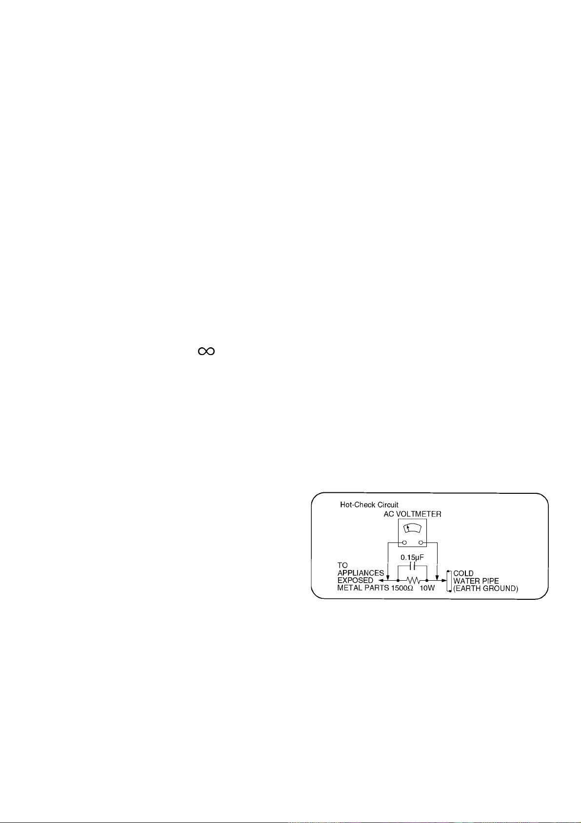
1.1.2. Leakage Current Hot Check (See
Figure 1.)
1. Plug the AC cord directly into the AC outlet. Do not use
an isolation transformer for this check.
2. Connect a 1.5kohm, 10 watts resistor, in parallel with a
0.15F capacitors, between each exposed metallic part
on the set and a good earth ground such as a water pipe,
as shown in Figure 1.
3. Use an AC voltmeter, with 1000 ohms/volt or mor
sensitivity, to measure the potential across the resistor.
4. Check each exposed metallic part, and measure the
voltage at each point.
5. Reverse the AC plug in the AC outlet and repeat each of
the above measurements.
6. The potential at any point should not exceed 0.75 volts
RMS. A leakage current tester (Simpson Model 229 or
equivalent) may be used to make the hot checks, leakage
current must not exceed 1/2 milliamp. In case a
measurement is outside of the limits specified, there is a
possibility of a shock hazard, and the equipment should
be repaired and rechecked before it is returned to the
customer.
e
Figure 1
3
2 WARNING
2.1 Prevention of Electrostatic Discharge (ESD) The equipment is sensitive to electrostatics (ES).
Some semiconductor devices (solid state) can easily be damaged by static electricity. Usually they called Electrostatic Sensitive Devices
(ES). Typical examples of devices are integrated circuits ES, some field effect transistors and semiconducting components [chip]. The
following techniques should be used to help reduce the incidence of component damage by electrostatic discharge (ESD).
1. Immediately before dealing with any semiconductor component or semiconductor assembly. Drain out of his body the ESD charge by
touching a known ground. Together, get a wrist strap to discharge electrostatic energy, for greater protection for ESD sensitive devices.
2. After removing a semiconductor device ES, put the device in a conductive material such as aluminum foil, to prevent electrostatic
charge or increased exposure assembly.
3. Use grounded soldering iron to solder or unsolder ES devices.
4. Use only antistatic solder remover. Some remover devices are not classified as [Antistatic (ESD)] can generate electrical charge
sufficient to damage ES devices.
5. Do not use freon chemicals. These can generate electrical charges sufficient to damage ES devices.
6. No one is immediately remove its protective packaging until before you are ready to install the device. (ES devices are packaged
replacements must be protected from electrical shorts with conductive foam, aluminum foil or comparable conductive material).
7. Immediately before removing the protective material ES device, touch the protective material to the chassis or circuit assembly into
the device to be installed.
Caution
Ensure that no voltage is applied to the chassis or circuit, and observe all other safety precautions.
8. Minimize bodily motions when dealing with the replacement ES devices.
SYMBOLS USED IN DEVICES SUBJECT TO ESD.
2.2. About lead free solder (PbF)
Note: Lead is listed as (Pb) in the periodic table of elements.
In the information below, Pb will refer to Lead solder, and PbF will refer to Lead Free Solder.
The Lead Free Solder used in our manufacturing process and discussed below is (Sn+Ag+Cu).
That is Tin (Sn), Silver (Ag) and Copper (Cu) although other types are available.
This model uses Pb Free solder in it’s manufacture due to environmental conservation issues. For service and repair work, we’d
suggest the use of Pb free solder as well, although Pb solder may be used.
PCBs manufactured usin
Caution
• Pb free solder has a higher melting point than standard solder. Typically the melting point is 50 ~ 70 °F (30~40 °C) higher. Please
use a high temperature soldering iron and set it to 700 ± 20 °F (370 ± 10 °C).
• Pb free solder will tend to splash when heated too high (about 1100 °F or 600 °C).
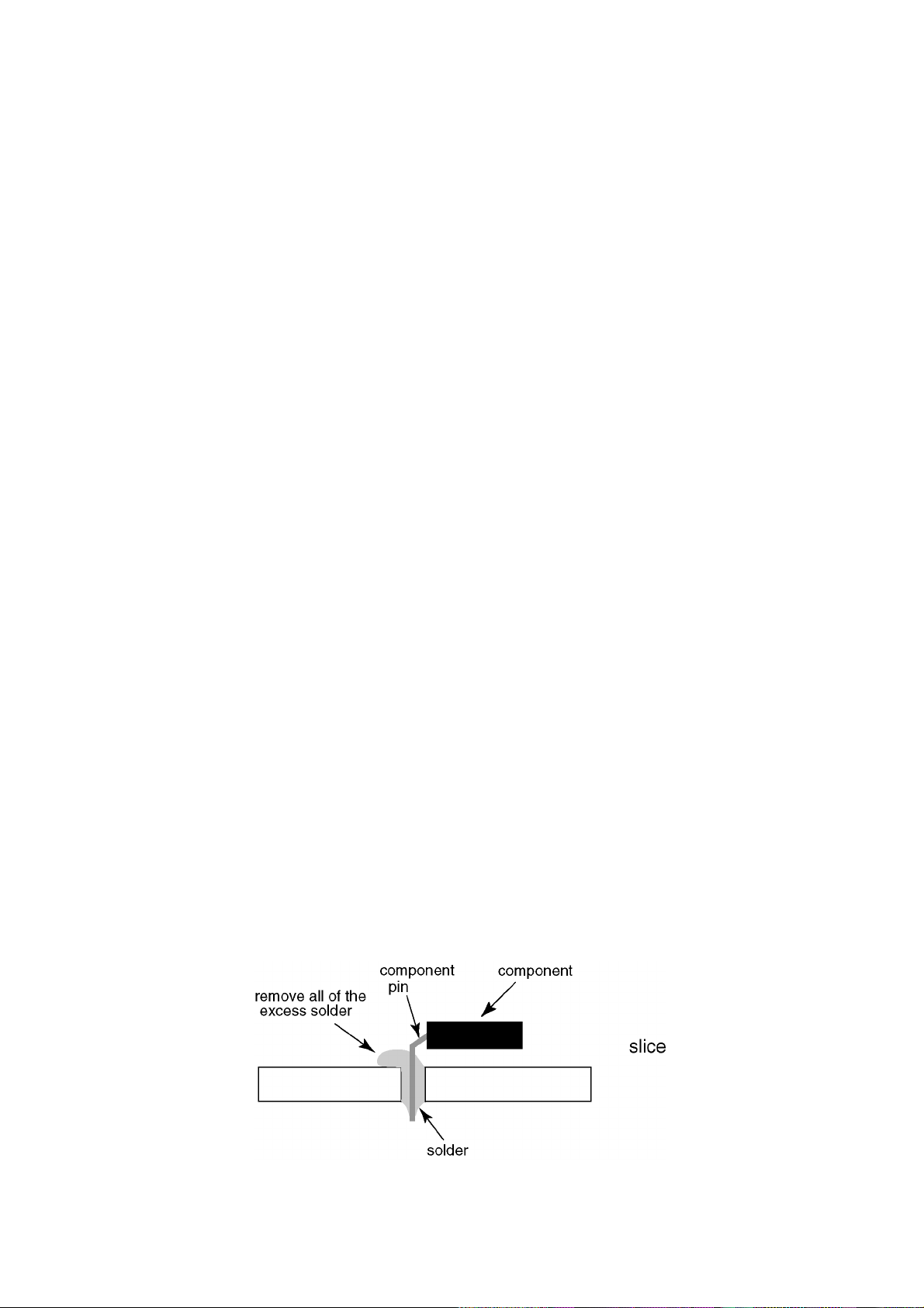
If you must use Pb solder, please completely remove all of the Pb free solder on the pins or solder area before applying Pb
solder. If this is not practical, be
• After applying PbF solder to double layered boards, please check the component side for excess solder which may flow onto the
opposite side. (see figure below)
g lead free solder will have the PbF within a leaf Symbol PbF stamped on the back of PCB.
sure to heat the Pb free solder until it melts, before applying Pb solder.
4
5
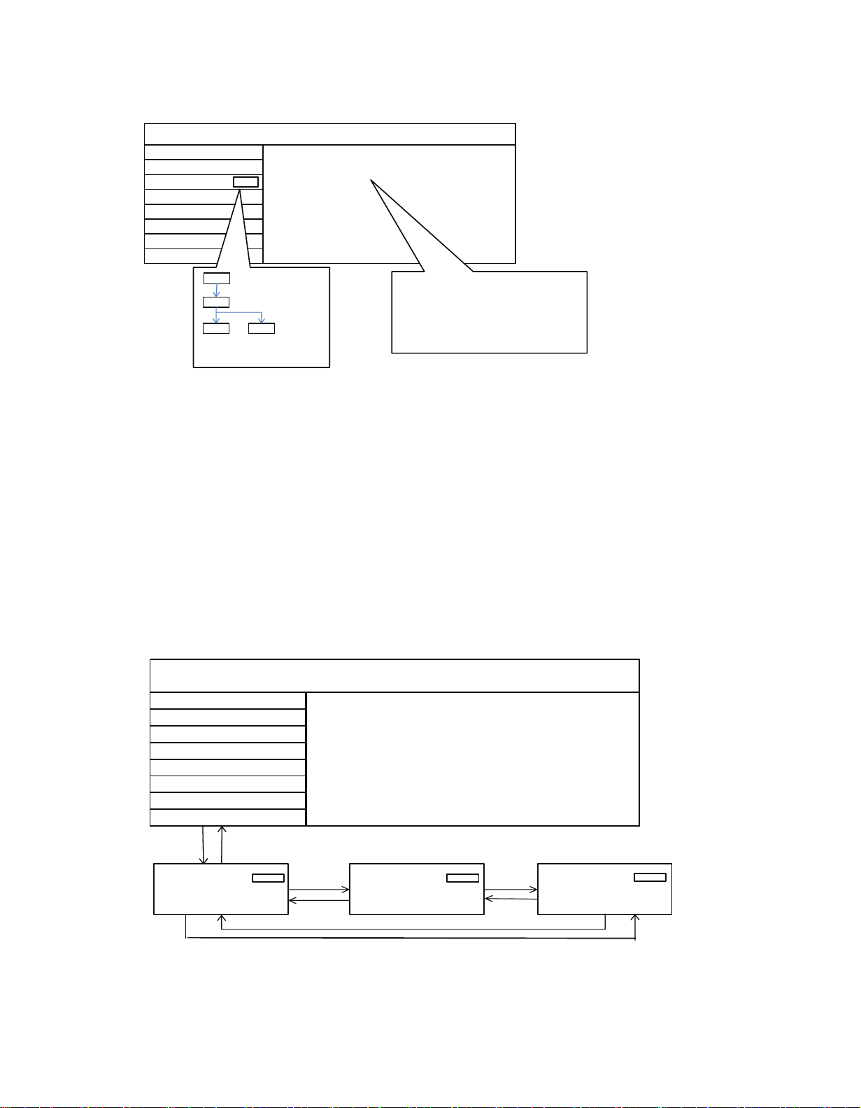
3. SERVICE
How to enter into CS Maintenance Menu
3.1. Purpose
After exchange parts, check and adjust the contents of adjustment mode.
While pressing [VOLUME ( - )] button of the main unit, press [ RED ] button of the remote control three times within 2 seconds.
Note:
CS Maintenance Menu can not be entered when 3D signal input.
Input 2D signal to enter CS Maintenance Menu.
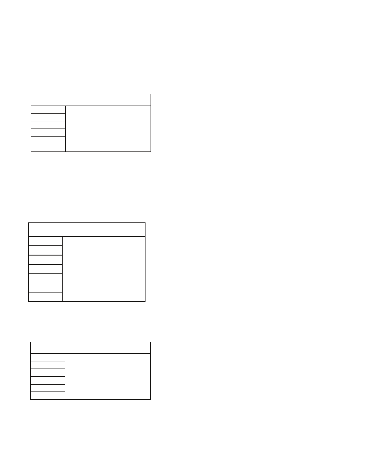
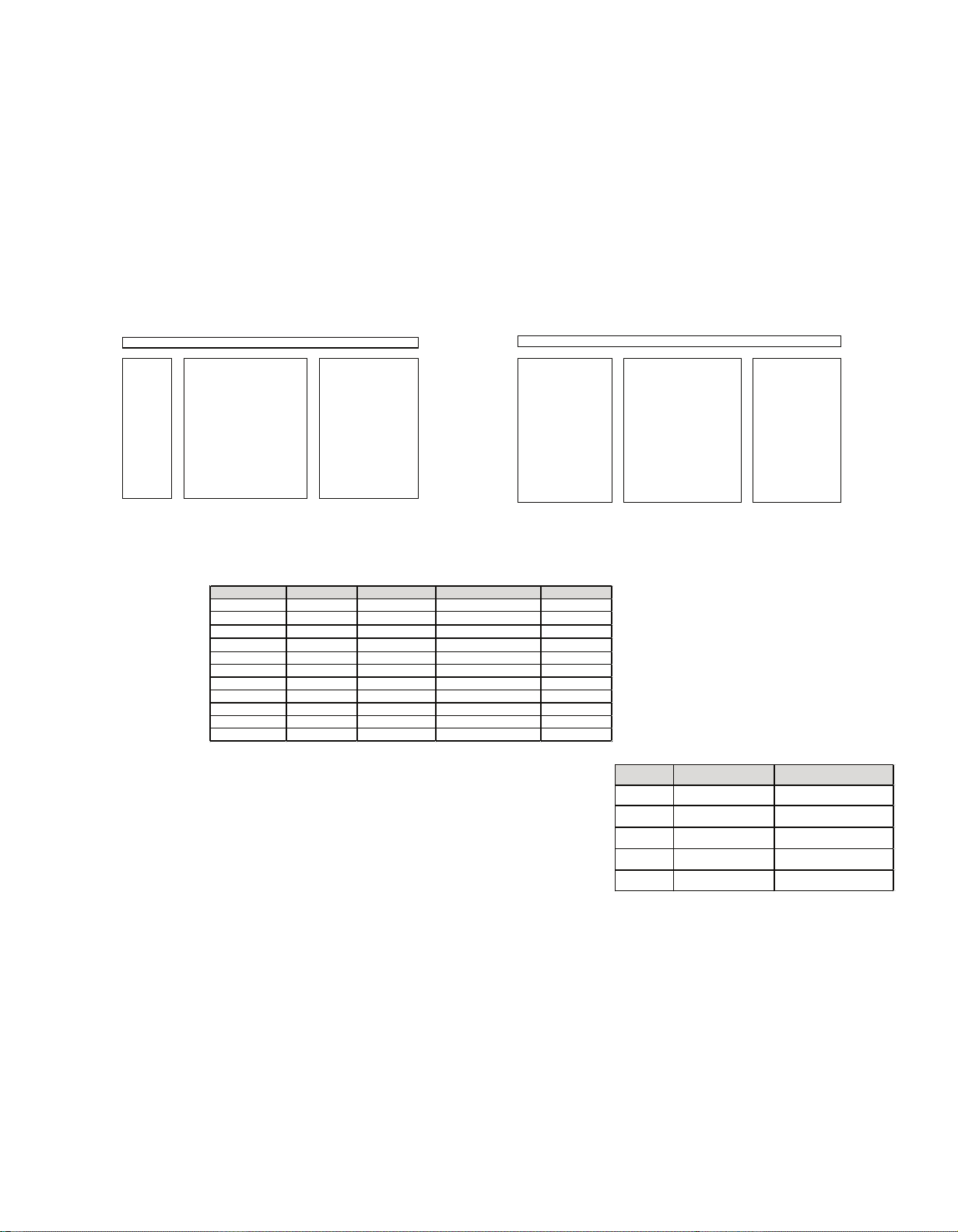
CS Maint enance Menu
OPT
WB - ADJ
EDID CLOCK
DRV CHECK
3.2. Key command
Press the Cursor key [Up/Down] on the remote control to select the functions.
3.3. How to exit
Press the [EXIT] button on the remote control.
3.4 Repack
1. Select [OPT] in CS Maintenance Menu.
2. Press [OK] button or Cursor key [Right] on the remote control.
7 6 5 4 3 2 1 0
0 0 0 0 0 1 0 1
1 1 1 0 1 1 1 0
0 0 0 0 0 0 0 1
0 0 0 0 0 0 1 0
OPT 2
OPT 3
OPT 4
OPT
EDID CLOCK
OPT 1
CS Maintenance Menu
DRV CHECK
WB - ADJ
row: OPT1
Column: 4
0: Automatic (Default)
1: Manual
3.5. EDID Clock
1. Select [EDID CLK] in CS Maintenance Menu.
2. Press [OK] button or Cursor key [Right] on the remote control.
CS Maintenance Menu
OPT
WB - ADJ
EDID CLOCK
DRV CHECK
EDID - CLK
HDMI 1
S-HIGH
Clock speed
HDMI number
Exit:
Press the [Exit] button or the [Return] button on the remote control.
6
4.0 USB HDD Drive Check (Only for models with DVR check MENU)
1. Select [DRV CHECK] in CS Maintenance Menu.
2. Press [OK] button or Cursor key [Right] on the remote control.
5.0 White Balance Adjustment
After LCD PANEL or A-Board is replaced and repaired, perform [White balance adjustment] in case of necessity for test /
check ([White balance adjustment] is not required basically).
1. Select [W/B ADJ] in CS Maintenance Menu.
2. Press [OK] button on the remote control.
Note for performing [White balance adjustment]
Make a note for the setting values before changing if the settings of [R-GAIN], [B-GAIN] and [G-GAIN] in [WB-ADJ]
will be changed.
3. Press the cursor key [Up/Down] on the remote control to change the data value, and press [OK] button on the remote
control to store the value for this model.
• COLOR TEMP : Press the [Option] button of the remote control to change the color temperature.
(COOL/NORMAL/WARM/TUNNIG)
DataTraveler 2.0 - OK
ERROR - NG
CS Mainten ance Menu
DVR CHECK
ERROR - NG
WB - ADJ
OP T
EDID CLK
OK
Press [OK] bu on (3s ec)
BUSY
Performing (Max 3 minutes)
OK
NG
OK HD D is normal
NG HD D is failure or mismatch
USBDD che ck History
***** ***−** OK ...... This me : OK
ERROR−NG ................. Last me : NG
****** ***** OK ..... Before last me: OK
WB - ADJ
CS Maintenance Menu
OPT
EDID CLK
WB- ADJ
R-GAIN
COLOR TEMP NORMAL
6E
WB- ADJ
R-GAIN
COLOR TEMP NORMAL
80
WB- ADJ
R-GAIN
COLOR TEMP NORMAL
77
[ Le ]
[ Rigth ]
[ Rigth ]
[ Le ]
[ Le ]
[ Le ]
Exit:
Press the [Return] button on the remote control.
Exit:
Press the [Return] button on the remote control.
7
5.1. System Information
5.1.1 How to access
1. While pressing [MENU] button on the remote control.
2. To select [? Help] and then to select [System Information].
SW version 2242-10000-abcde
3001
10000
abcde
Peaks SW
GenX Main
GenX Sub (optional)
Status1 0c 8801-0003 0080-0000
0c
8801-0003
0080-0000
Outer model ID
Inner model ID
Panel inch size
Status2 0008-008-000fac
0008
008
000fac
LSI Package
LSI Release
Model data version
Status3 00-000000-F000
00
00
00
00
F000
Number of bad block in NAND Flash (dec)
Peaks reboot counter
System crash counter
Emergency (SOS) counter
Peaks NAND Maker ID
Status4 A00000-0000003-00000
A
00000
0000003
00000
Power-On period (A <= 100hrs, B <= 200hrs, C > 200hrs)
Total Power-On time (dec, max is 65535)
Power-On timer (dec, max is 1048575)
Fixed (always)
Status5 00000-10000 15e010ff
0
0
0
0
0
1
0000
15e010ff
SOS history (latest)
SOS history (last time)
SOS history (last but one)
SOS history (2nd time after shipping)
SOS history (1st time after shipping)
Self-check _0-never selfcheck
1-production selfcheck by "FF" or USCM
2-user selfcheck by pressing "OK"
Fixed (always)
Panel ID
Status6 01010010-1000009
01010010
1000009
Peaks EEPROM version
STM EEPROM version
Status7 00000-0741
00000
0741
STM ROMCOR version
AJAX_CE version
HDAVI Control
5 VIERA Link version is displayed
TC-58DX800C
TC-65DX800C
System Information
8
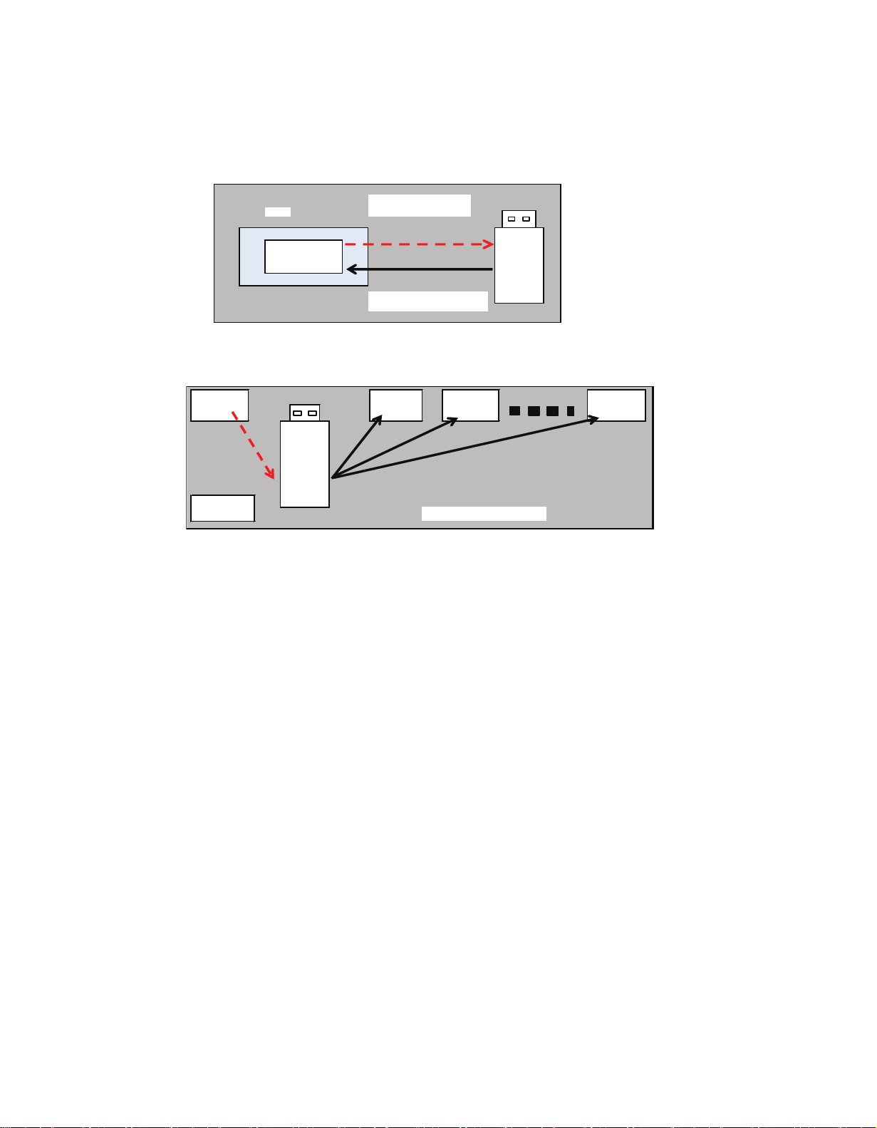
5.2. Data Copy by USB Memory
Note:
SD card can not be used for Data Copy.
Purpose
(a) Board replacement (Copy the data when exchanging A-board):
When exchanging A-board, the data in original A-board can be copied to USB Memory and then copy to new A-board.
A
USB
Memoria
TV
(Before exchanging)
Copy to USB Memory
(Aer exchanging)
Copy back from USB Memory
5.3. Preparation
Make pwd file as startup file for (a) or (b) in a empty USB Memory.
1. Insert a empty USB Memory to your PC.
2. Right-click a blank area in a USB Memory window, point to New, and then click text document. A new file is created by
default
(New Text Document.txt).
3. Right-click the new text document that you just created and select rename, and then change the name and extension
of the
file to the following file name for (a) or (b) and press ENTER.
File name:
(a) For Board replacement : boardreplace.pwd
(b) For Hotel : hotel.pwd
Note:
Please make only one file to prevent the operation error.
No any other file should not be in USB Memory.
other TV
Copy from USB memory
Master TV
USB
Memory
Copy to USB
other TV
other TV
Following data can be copied.
User settings data
(Incl. Hotel mode setting data)
Channels scan data
Adjustment and factory preset data
Following data can be copied.
User setting data
(incl. Hotel mode setting data)
Channel scan data
(b) Hotel (Copy the data when installing a number of units in hotel or any facility):
When installing a number of units in hotel or any facility, the data in master TV can be copied to USB Memory and then copy to other TVs.
9
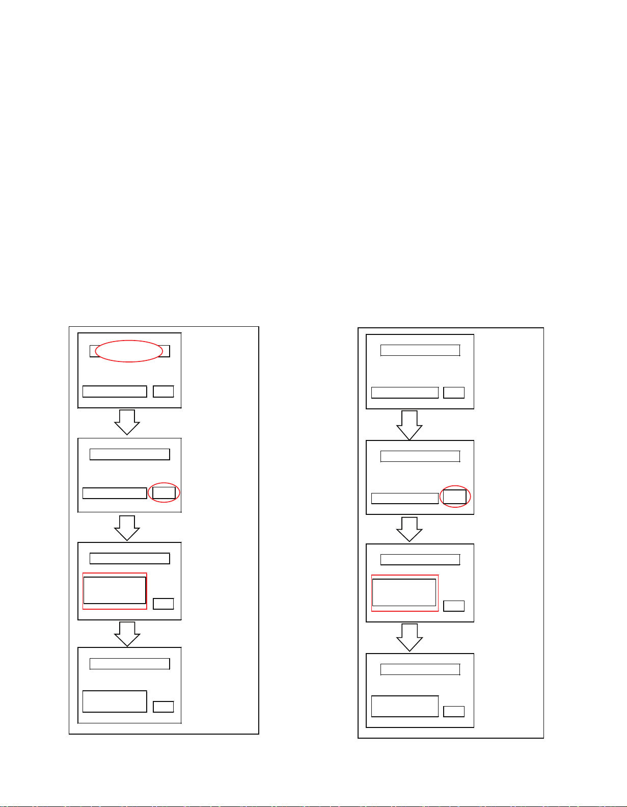
5.4 Data copy from TV set to USB Memory
1. Turn on the TV set.
2. Insert USB Memory with a startup file (pwd file) to USB
terminal.
On-screen Display will be appeared according to the startup
file automatically.
3. Input a following password for (a) or (b) by using remote
control.
(a) For Board replacement : 2770
(b) For Hotel : 4850
Data will be copied from TV set to USB Memory.
It takes around 2 to 6 minutes maximum for copying.
4. After the completion of copying to USB Memory, remove
USB Memory from TV set.
5. Turn off the TV set.
Note:
Following new folder will be created in USB Memory for
data from TV set.
(a) For Board replacement : user_setup
(b) For Hotel : hotel
5.5. Data copy from USB Memory to TV set
1. Turn on the TV set.
2. Insert USB Memory with Data to USB terminal.
On-screen Display will be appeared according to the
Data folder automatically.
3. Input a following password for (a) or (b) by using
remote control.
(a) For Board replacement : 2771
(b) For Hotel : 4851
Data will be copied from USB Memory to TV set.
4. After the completion of copying to USB Memory,
remove USB Memory from TV set.
(a) For Board replacement : Data will be deleted after
copying (Limited one copy).
(b) For Hotel : Data will not be deleted and can be used
for other TVs.
5. Turn off the TV set.
Note:
1. Depending on the failure of boards, function of Data
copy for board replacement does not work.
2. This function can be effective among the same model
numbers.
Input Password
277 0
or
458 0
Data c opy
(Board repla cement)
or (Hotel)
Data copy (
*******
)
Compleon
(e.g. excha nging repai r board)
Performi ng
Perform ing
Dat a copy
(*******
)
Input pa ssword
Input Password
Dat a copy has be en succes ful.
Ple ase remo ve the Media.
FINISH
Input pa ssword
─
Data copy (
*******
)
GETTING
Data copy
****
Copy TV to Medi a
Ple ase wait for a white
Ple ase do not remove the
Performi ng
Data c opy (
*******
)
Data copy has bee n succes ful.
Ple ase turn off TV system
Compleon
FINISH
WRITI NG
Performi ng
Data c opy (
*******
)
(e.g. For exchangi ng
repa ir board)
Input pa ssword
─
Data c opy
(
*******
)
Input Password
277 1
or
458 1
Input pa ssword
Input Password
Data c opy (
*******
)
****
Copy TV to Medi a
Ple ase wait for a white
Ple ase do not remove the
10
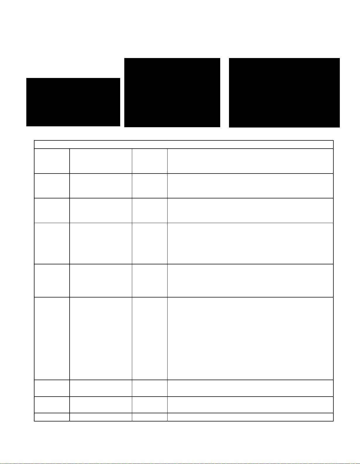
6 Troubleshooting Guide
Use the self-check function to test the unit.
1. Checking the IIC bus lines
2. Power LED Blinking timing
6.1. Check of the IIC bus lines
6.2. How to access
6.3. SSelf-check indication only:
Produce TV reception screen, and while pressing [VOLUME ( - )] button on the main unit, press [BLUE] button on the
remote control for more than 3 seconds.
6.4. Self-check indication and forced to factory shipment setting:
Produce TV reception screen, and while pressing [VOLUME ( - )] button on the main unit, press [MENU] button on the
remote control for more than 3 seconds.
6.5. Screen display
TC-65DX800C
TC-58DX800C
6.6 Check Point
Confirm the following parts if NG was displayed.
Exit:
Disconnect the AC cord from wall
outlet or press the [POWER] button on
the main unit for 3 seconds to turn off
and then turn on automatically.
6.7. Power LED Blinking timing chart
1. Subject
Information of LED Flashing timing chart.
2. Contents
When an abnormality has occurred the unit, the protection circuit operates and reset to the stand by mode. At this time, the
defective block can be identified by the number of blinks of the Power LED on the front panel of the unit.
DISPLAY Check Ref. No. Descripon
H14TUN TU6702 TU6709 TUNER A-BOARD
H15TUN2 TU6709 TUNER A-BOARD
H38FRC IC9000 FRC A -BOARD
H07TEMP IC2250 TEMP SENSOR A-BOARD
H17LAN ETHERNET A-BOARD / LAN
H00FE IC6800 IC6802 DEMODULATOR A-BOARD
H00SAT-TU IC6802 SAT-TUNER A-BOARD
H96ID I D A-BOARD
H97ID2 ID2 A-BOARD
H45BT Bluetooth A-BOARD / BT
H42WiFi WiFi A-BOARD / WiFi
Blinking item Check point
1 BL SOS LCD PANEL/P-Board
7 SUB 3.3V /1.0V P-Board/ A-Board
9 SOUND SOS A-Board/Speaker
10 FRC/NVT SOS A-Board
13 EMERGENCY SOS A-Board
OK
OK
OK
OK
OK
OK
OK
OK
SELF CHECK COMPLETE
H14TUN
PEAKS - SOFT
2.242
MODEL ID
0d
H38FRC
PEAKS - EEP
02 . 14 . 5832
0 3000232
H07TEMP
LSI- PACKAGE
0 . 024
0 0020000
H17LAN
LSI - RELEASE
1 . 11
H00FE
STBY - SOFT
1 . 00 . 00
H96ID
STBY - EEP
1. 00 . 0021
H97ID2
FRC SOFT
00001d11
H42WiFi
FRC DATA
0 0060016
OK
OK
OK
OK
OK
OK
OK
OK
0 3000232
0 0080000
02 . 14. 6532
1 . 00 . 00
1. 00 . 0021
00001d11
0 0060016
TCON DATA
2.242
0 . 024
1.11
PEAKS - SOFT
PEAKS - EEP
LSI- PACKAGE
LSI - RELEASE
STBY - SOFT
STBY - EEP
H38FRC
H07TEMP
H17LAN
H96ID
H97ID2
SELF CHECK COMPLETE
H14TUN
H42WiFi
TCON SOFT
MODEL ID
0d
6.8. LCD Panel test mode
Purpose:
To find the possible failure point where in LCD Panel or Printed Circuit Board when the abnormal picture is displayed.
How to Enter:
While pressing [VOLUME ( - )] button of the main unit, press [YELLOW] button of the remote control three times within 2
seconds.
How to Exit:
Switch off the power with the [POWER] button on the main unit or the [POWER] button on the remote control.
How to confirm:
If the abnormal picture is displayed, go into LCD Panel test mode to display the several test patterns.
And then, judge by the following method.
Still abnormal picture is displayed: The cause must be in LCD Panel.
Normal picture is displayed: The cause must be in A board.
Remarks:
The test pattern is created by the circuit in LCD Panel.
In LCD Panel test mode, this test pattern is displayed unaffected by signal processing for RF or input signal.
If the normal picture is displayed, LCD Panel must be okay and the cause of failure must be in A board.
11
7
Hotel mode
1. Purpose
Restrict a function for hotels.
2. Access command to the Hotel mode setup menu.
In order to display the Hotel mode setup menu:
While pressing [VOLUME (-)] button of the main unit,
press [AV] button of the remote control three times within
3 seconds.
Then, the Hotel mode setup menu is displayed.
Item Function
Mode Select hotel mode On/Off
Input Select input signal modes.
Set the input, when each time power is
switched on.
Selection:
Off, Analogue TV, Digital TV, AV,
HDMI1,HDMI2, HDMI3, HDMI4, DisplayPort
• Off: give priority to a last memory.
Channel Select channel when input signal is RF.
Set the channel, each time power is switched
on.
Selection:
Any channel number or [-].
[-] means the channel when turns off.
Volume Adjust the volume when each time power is
switched on.
Range:
0 to 100
Vol. Max Adjust maximum volume.
Range:
0 to 100
OSD Ctrl Restrict the OSD.
Selection:
Off/Pattern1
• Off: No restriction
• Patte
rn1:
restriction
FP Ctrl Select front key conditions.
Selection:
Off/Pattern1/All
• Off: altogether valid.
• Pattern1: only input key is valid.
• All: altogether invalid.
Pow Ctrl Select POWER-On/Off condition when AC
power cord is disconnected and then connecte
Off: The same condition when AC power
cord is disconnected.
On: Forced power ON condition.
3. To exit the Hotel mode setup menu
Disconnect AC power cord from wall outlet.
4. Explain the Hotel mode setup menu
12
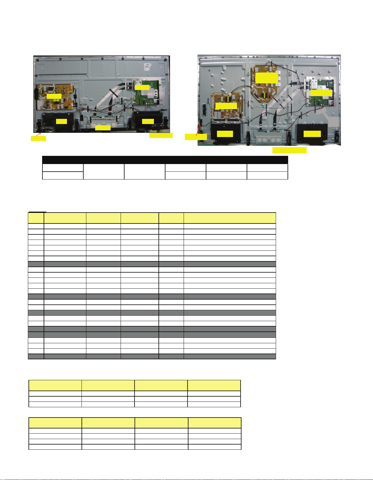
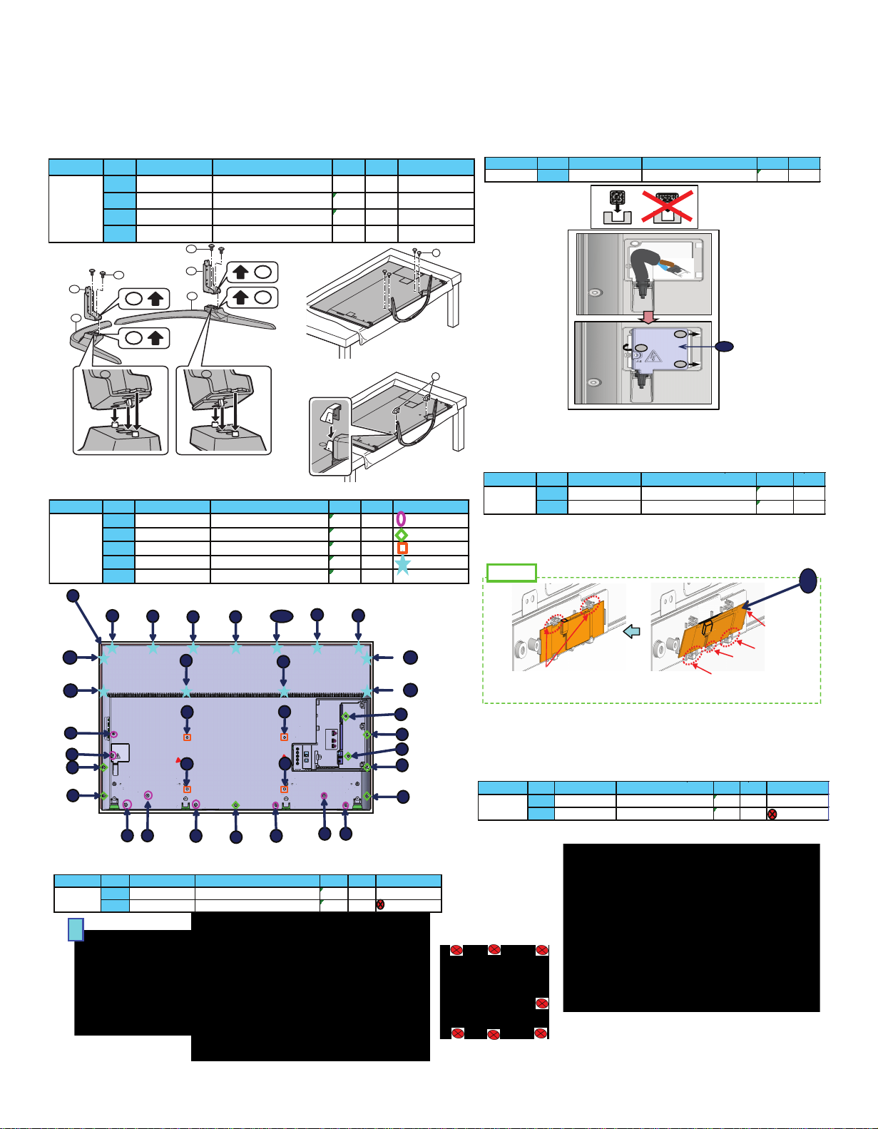
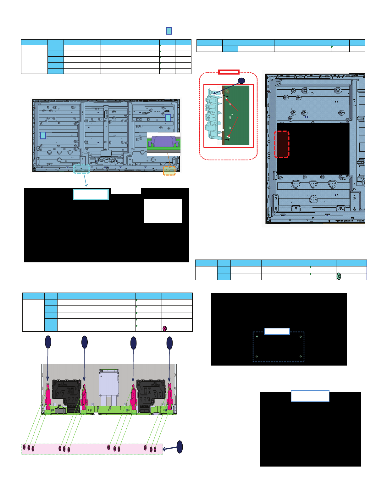
8 Voltage Confirmation
8.1 PCBs Layout.
TC-65DX800C
IR/AI/LED
Wi-Fi
P PCB
A PCB
SP
PB
BARD
SP
Model PCB A PCB K PCB P PCB GK PCB PB
TC-58DX800C
TC-65DX800C
TNPH1147-1
TNPA6056-1
TNPA6060-2
TNPA6198-1
TNPA6063-2
TNPA6249-1
TC-58DX800C
TNPH1147
A
SD3.3V
TP8644
3.34V ± 0.17V
output
A
JPN/BRA_1.2V
TP5708
1.22V ± 0.11V
output
A
T2_1.1V
TP5705
1.15V ± 0.11V
output
A
JPN_3.3V
TP5706
3.3V ± 0.17V
output
A
SUB9V
TP5004
9V ± 0.4V
output
A
LNB_PWR1
TP6702
15V ± 1.5V
output
A
EU_TU_1.8V
TP5704
1.84V ± 0.1V
output
A
WOL3.3V/PHY3.3V
TP8606
3.3V ± 0.17V
output
A
GE_1.1V
TP4450
1.10V - 1.19V
output
A
MSTAR0.95V
TP9150
1.00V ± 0.07V
output
A
MSTAR1.5V
TP9160
1.50V ± 0.07V
output
A
NT2.5V
TP9170
2.52V ± 0.12V
output
A
AVDD1.0V
TP8102
1.06V ± 0.05V
output
A
SUB1.0V
TP8100
1.02V + 0.03V -0.05V
outputASTB_1.5V
TP8101
1.52V ± 0.07V
output
A
SUB_AI_3.3V
TP2206
3.3V ± 0.17V
output
A
HDMISW3.3V
TP4514
3.35V ± 0.17V
output
A
HDMI1.1V
TP4503
1.13V ± 0.06V
output
A
SUB3.3V
TP5201
3.33V ± 0.15V
output
A
USB-WiFi
TP8718
5.14V ± 0.20V
output
A
USB3
TP8705
5.0V ± 0.25V
output
A
USB2
TP8701
5.0V ± 0.25V
output
A
USB1
TP8711
5.0V ± 0.25V
output
A
USB5V
TP5221
5.18V ± 0.25V
output
A
PNL12V
TP4059
12V ± 1.2V
output
PCB
Test point name
Test point
Specifica tion
In/Out
Remarks
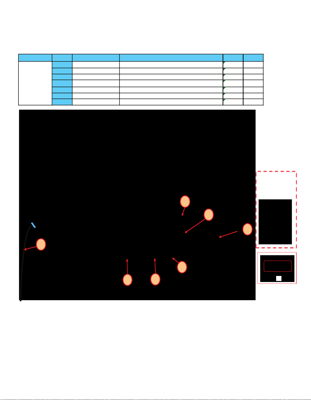
8.2 Letter voltages for PCB A
Check satisfaction with the specified voltage in the following table:
TNPA6060
*HOT
PFC
TP7201/02
<340V
400V ±15V
16V
TP7410/11/12
< 1V
16±0.6V
5VS
TP7501/02
5.1±0.2V
5.1±0.2V
Output
Test point
TV Off
TV ON
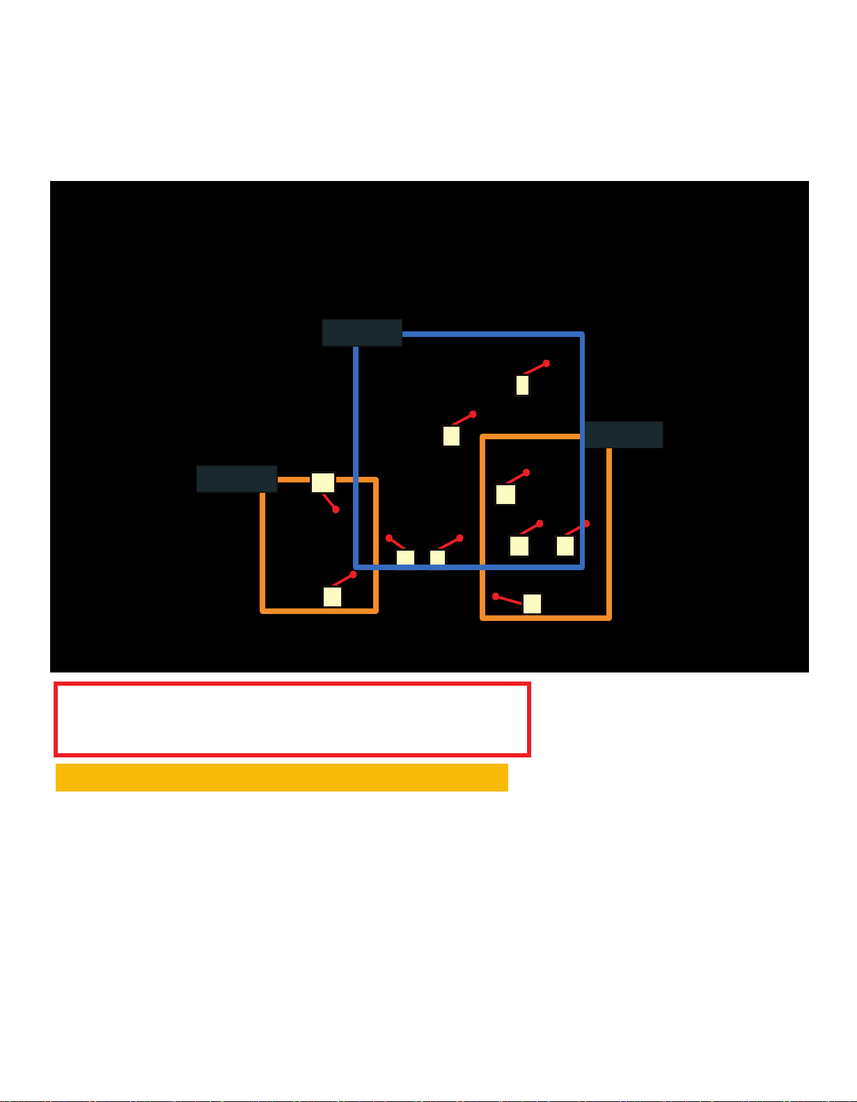
8.3 PCB P (Power board Voltage chart).
IR/AI/LED
Wi-Fi
SP
SP
T-CON
P PCB
A PCB
--------
--------
TNPA6198
*HOT
64V
TP7408/09
< 1V
68V ±10V
PFC
TP7201/02
<340V
390V ±15V
16V
TP7410/11/12
< 1V
16±0.6V
5VS
TP7405/20
5.25±0.2V
5.25±0.2V
Output
Test point
TV off
TV ON
13
9 Specifications
Display Panel
Panel System
LCD panel with LED backlight
Refresh Rate
120 Hz
Screen size
•
TC-58DX800C
58 ” class (57.5 inches measured diagonally)
•
TC-65DX800C
65 ” class (64.5 inches measured diagonally)
W × H × Diagonal
•
TC-58DX800C
50.0 ” × 28.4 ” × 57.5 ”
(1,270 mm × 721 mm × 1,461 mm)
•
TC-65DX800C
56.2 ” × 31.6 ” × 64.5 ”
(1,428 mm × 804 mm × 1,639 mm)
Number of pixels
3,840 × 2,160
Speaker Output
20 W [10 W + 10 W]
Channel Capability (Digital/Analog)
VHF/ UHF: 2 - 69, CATV: 1 - 135
Operating Conditions
Temperature: 32 °F - 95 °F (0 °C - 35 °C)
Humidity: 20 % - 80 % RH (non-condensing)
Connection Terminals
VIDEO IN
RCA PIN (VIDEO, AUDIO-L, AUDIO-R)
COMPONENT IN
RCA PIN (Y, PB/CB, PR/CR, AUDIO-L, AUDIO-R)
HDMI IN 1/2/3/4
Type A connector
(supports “HDAVI Control 5” function)
USB 1/2/3
Type A connector
USB 1: DC 5 V, Max. 900 mA
[SuperSpeed USB (USB 3.0)]
USB 2/3: DC 5 V, Max. 500 mA
[Hi-Speed USB (USB 2.0)]
DIGITAL AUDIO OUT
PCM / Dolby Digital / Fiber Optic
OTHERS
ETHERNET (10BASE-T/100BASE-TX)
Dimensions
Including pedestal (W × H × D)
•
TC-58DX800C
(Style1/Style2)
50.8 ” × 32.0 ” × 14.8 ”
(1,290 mm × 813 mm × 376 mm)
(Style3/Style4)
52.6 ” × 31.4 ” × 14.8 ”
(1,336 mm × 798 mm × 376 mm)
•
TC-65DX800C
(Style1)
57.2 ” × 35.6 ” × 14.3 ”
(1,453 mm × 903 mm × 363 mm)
(Style2)
57.2 ” × 36.1 ” × 14.3 ”
(1,453 mm × 918 mm × 363 mm)
TV Set only (W × H × D)
•
TC-58DX800C
50.8 ” × 29.6 ” × 1.6 ”
(1,290 mm × 753 mm × 41 mm)
•
TC-65DX800C
57.2 ” × 33.0 ” × 2.4 ”
(1,453 mm × 838 mm × 61 mm)
Mass
Including pedestal
•
TC-58DX800C
54.1 lb. (24.5
) NET
•
TC-65DX800C
61.8 lb. (28.0
) NET
TV Set only
•
TC-58DX800C
50.7 lb. (23.0
) NET
•
TC-65DX800C
59.6 lb. (27.0
) NET
Wireless LAN
Standard Compliance and Frequency
Range
*
1,
*
2
IEEE 802.11a/n: 5.15 GHz - 5.35 GHz,
5.47 GHz - 5.85 GHz
IEEE 802.11b/g/n: 2.400 GHz - 2.4835 GHz
Security
WPA2-PSK (TKIP/AES)
WPA-PSK (TKIP/AES)
WEP (64 bit/128 bit)
*
1 The frequency and channel differ depending on the
country.
*
2 802.11b/g/n CH1 ~ CH11 only use for United States
and Canada.
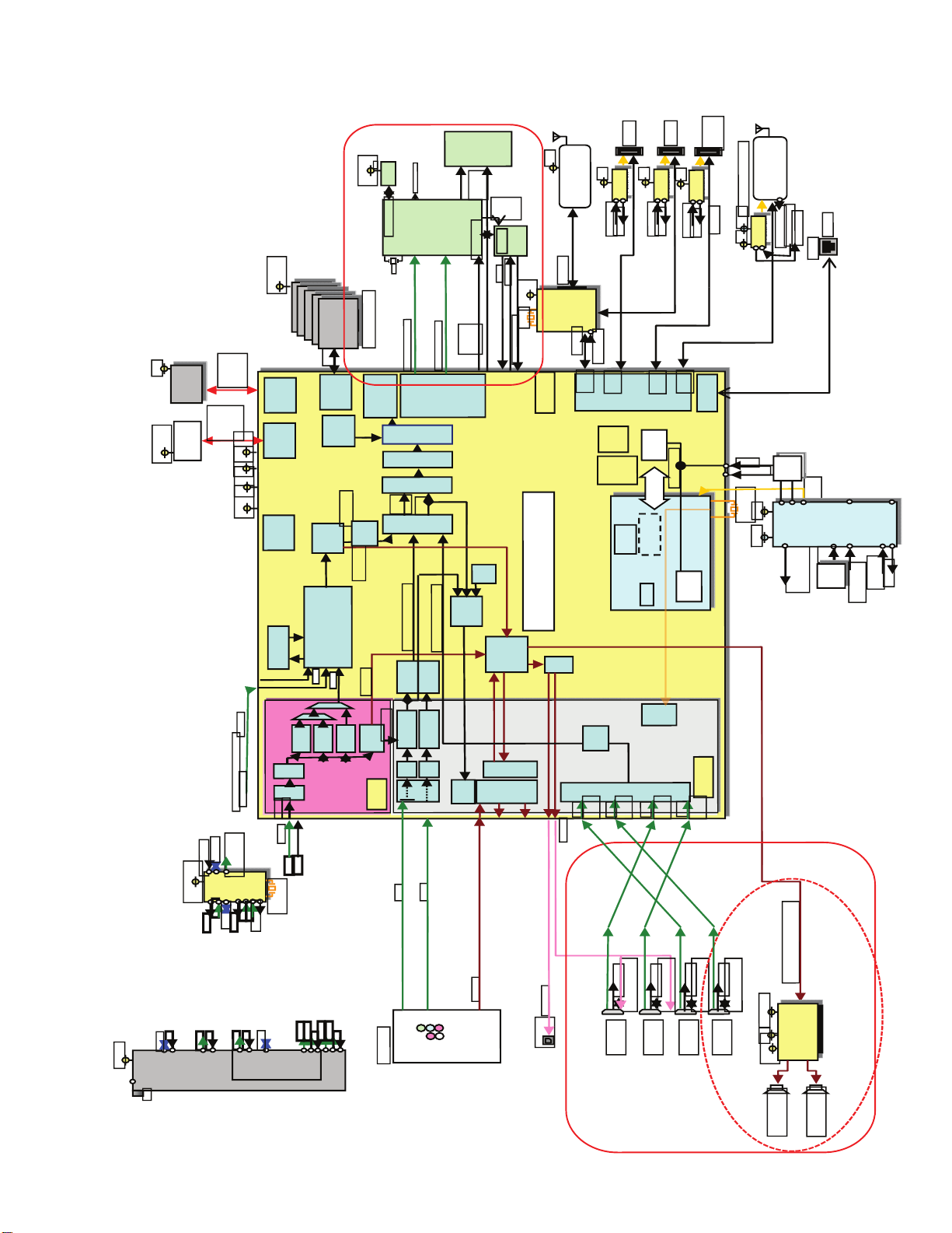
10. Block diagram
S3.3
eMMC
Debug
S5/ S3.3
XERST
MMCCLK
MMCCMD
32Gbit
CE#1
SDO
SDI
SCLK
Connector
USB-3
32Mb
S3 3
SPI-FLASH
R PANEL VCC ON
FR_CSZ/SDOSDISCK
MSTAR
DDR1.5
x16
DDR3
4MHz
4Gbit
DDR3 1866 4Gbx5
x80
MMCDAT0-7
DDR3
eMMC-IF
SPI-IF
S1 5
S3.3
S1.0
S1.05
Controller
OSD
1,2,3
cursor
Dec video
AV
SPI-IF
Decoder
VbyOne 8 Lane (Video)
T-CON
LVDS-Tx/
3D)
MJC
(FRC,
PQ
Scaler
n
Mai
Sub
MIB
B2R
(IPNR)
Dec Audio
(Tcon)
PNL 3D ON
PNL TEST ON
BL_EC
BL_ON
MFC11
VbyOne 4 Lane (OSD)
V-by-One
mini-LVDS Tx
LD
BL_PWM0-7
BL SOS
DISPEN
BL_ENB
FR RESET
5
OSD
S3.3
BT Module
O
3D_ON
P
TV SUB
EYSCAN/POWER KEY
USB2.0- F
S3.3
24MHz
GL850G
USB-HUB
USB2.0-IF
(Port 1
USB2.0
D-Chip
EASTER
S5
S5
HUB_XRST <
USB2.0
Serial
IIC
USB
USB
Power SW
< OVCUR
< OVCUR
USB*VBU >
USB*VBU >
po t 0)
(Port 2)
USB3.0
IF
x4
USB
Serial
1
ARM
BE_IIC2
BE_IIC1
BE_IIC0
STM-IIC
IIC
Serial
STM-Serial0
ADx8
Panel
USB-2
USB-1
(3.0 HDD)
S5
Power SW
HDD-USB
Power SW
USB3.0-IF
< OVCU
USB*VBU >
(Port 3)
USB2.0
IEEE802.11n
Wireless UNIT
Fo Wake up On W reless (Euro)
STB5.3
USB
S5
Power SW
WOW_ON_IRQ
10/100M
> WOW_OVP
< PHY PWR ON
ETHER
ETHER-IF
XR T
POW
Reset
C rcuit
Common Reset
μP
Paragon
STB3.3
24MHz
F15V
ASIC
Analog
STB5V
S S
OVP
Safety
Circuit
MONITOROUT MUT
AMP HP MUTE
< TV_SOS
PWMO T
PWM_ENB >
PWMA
< SP_HP_MUTE
< MON_MUTE
TVE
Exte nal Video(Analog)
Trans Port Demux
controller
Internal CI
SUB
MAIN
Dig tal SF
Wred OR
(TU_Para_TS1)
TU Ser al TS1 / TU_Serial_TS1_JP
BE- IC
< FE_XRST
TU_Serial_TS2
(TU_Para_TS2)
S3 3/ S1.2
E T IFAGC1
TU-IIC1
S3 3/S1.8
Ter
Double
EC
2
DVB-T2
DEMOD
2
F2
2
SAT GC2
TU- IC2
EXT AGC2
I GC
I
D SEqC
2
E IFAGC2
TU-IIC2
nd
For
2
Tuner
DVB-T
DVB-C
Decoder
Decoder
FLT
SAW
ADC
FE NN
FEA NP
Low-IF
IF1
FAGC1
41MHz
Q 1
I 1
Q 2
I_2
S T A C1
S T A C2
Digital CVBS
ATV
Decoder
Decoder
ATSC/QAM
DMD
Analog AV
Ex ernal Video(HDMI)
Pre
Processor
Processor
TV Decoder
Analog Video
[0]
[3:1]
ADC
ADC
V-SW
VDAC
YPbPr
CVBS
Y
Pr
Pb
L
R
DSP
Audio
SW
SPDIF
CLK
GEN
R2R
DAC
ADC
x4
Rx
A-SW
(Thru)
L/R in x 2
Rx0
ARC OUT
Optical OUT
OP
MUX
HDMI
Rx2
Rx
HDMI1.
4
HDMI1.
4
DDC* > STM
DDC* > STM
HDMI_5V_DET* > STM
HPD* < STM
HDMI2
HDMI1
A-Chip
Rx3
HDMI2.
0
HDMI2.
0
RST/#SOS/#AMP_MUTE
2S(MCLK LRCLK/BCLK/SDAT[10])
DDC* > STM
DDC* > STM
DDC* > STM
DDC* > STM
HDMI_5V_DET* > STM
HDMI_5V_DET* > STM
HPD* < STM
HPD* < STM
HDMI_5V_D > STM
HDMI_5V_D > STM
HPD* < STM
HPD* < STM
HDMI_5V_DET* > STM
HPD* < STM
HDMI4
HDMI3
X
SOUND_VCC
S1 8
I2S AMP
(YAMAHA)
YDA176-QZ
S3 3
14
Lch:10W
Rch:10W
15
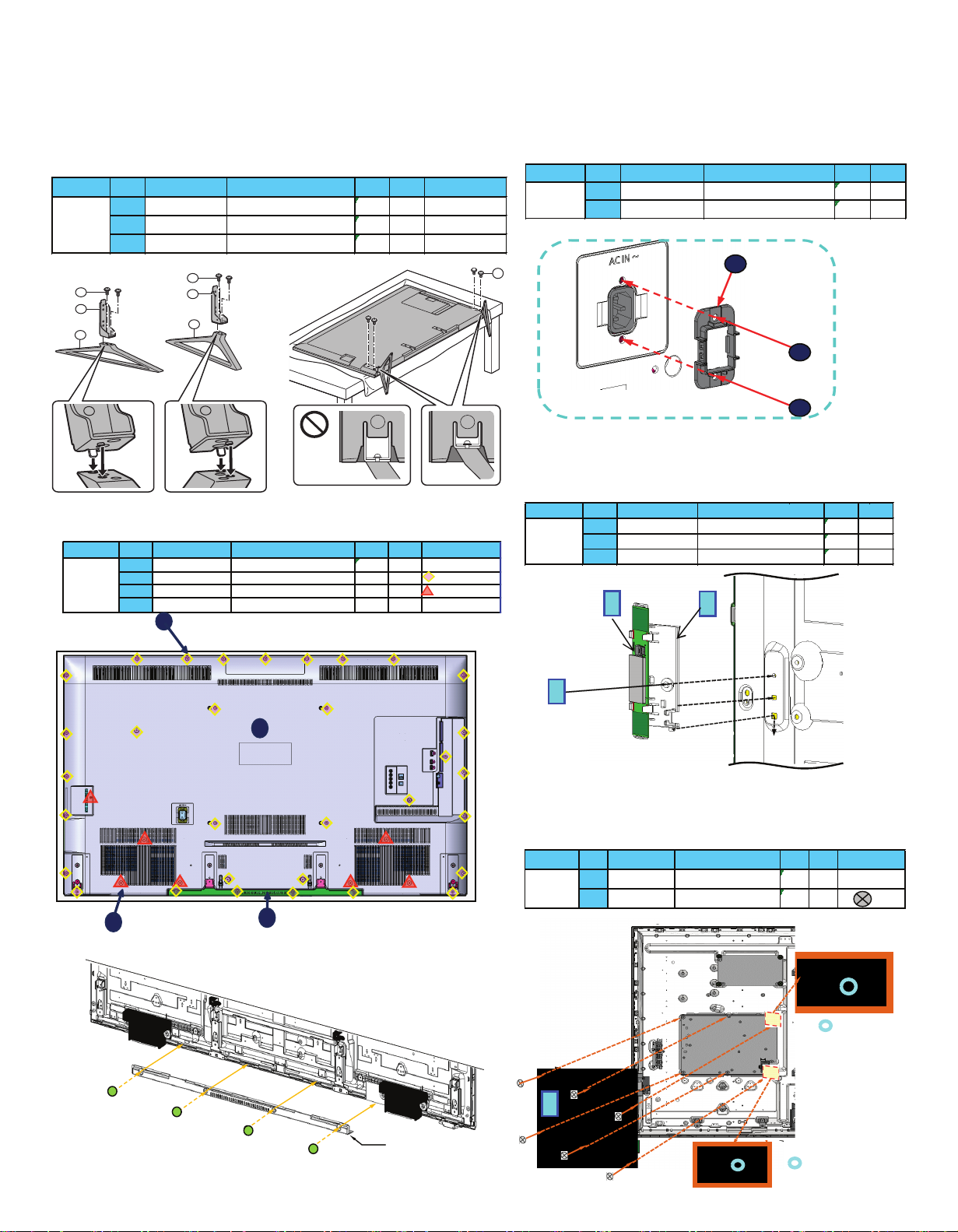
11 Assembly and disassembly instructions TC-65DX800C.
11.3 AC Inlet Disassembly
1. Remove the two screws (THEL0239).
2. Remove the AC Inlet hole.
1
2
2
11.4 Back cover
11.5. WIFI module
1. Remove the screws.
2. Remove the PCB bracket.
BOTTOM_BACK_COVER
4. Remove the back cover Bottom.
2
1
3
PCE
Unit
SCREW (HDMI)
2
PCE
2
THEL0239
Model
No.
Part number
Description
Qty.
TC-65DX800C
1
TKP5ZA56601
AC_INLET_HOLDER
1
11.6 Power board
1. Disconnect connectors.
2. Remove the 6 screws (THEJ036J).
3. Remove the PCB P.
2
2
2
2
Guide
Guide
1
A, B,C,D (KIT)
A
A
D
C
F
E
B
1
BACK_COVER
PCE
TKP5ZA56001
BOTTOM BACK COVER
Remarks
1
THEC2489
SCREW(BC30)
32
PCE
Unit
TTU3AA0133
2
Model
No.
Part number
Description
Qty.
4
1
PCE
TC-65DX800C
3
THTD037J
SCREW(SP4/CTRL1/AV3)
7
PCE
1
2
3
4
1
TKP5ZA52001
WIFI_MODULE
3
THEJ036J
WIFI_BRACKET
1
PCE
TC-65DX800C
1
PCE
1
PCE
SCREW M3
2
N5HBZ0000114
Model
No.
Part number
Description
Qty.
Unit
2
THEJ036J
M3 SCREW(A5/P7)
6
PCE
Notas
TC-65DX800C
1
TZRNP11EWVU
PCB P COMPLETE
1
PCE
Model
No.
Part number
Description
Cant.
Unidad
TC -65D X 800C
Remarks
PCE
3
TBL5ZX10901
STAND METAL ASSY-65U1
1
PCE
1
TBL5ZX11271
PEDESTAL_ASSY_L-65T1
1
PCE
2
TBL5ZX11281
PEDESTAL_ASSY_R-65T1
1
Model
No.
Part number
Description
Qty
Unit
F
E
11.1. Procedure disassembly of the unit.
11.2 Disassemble Pedestal
1. Remove the 4 screws (M4x12).
16
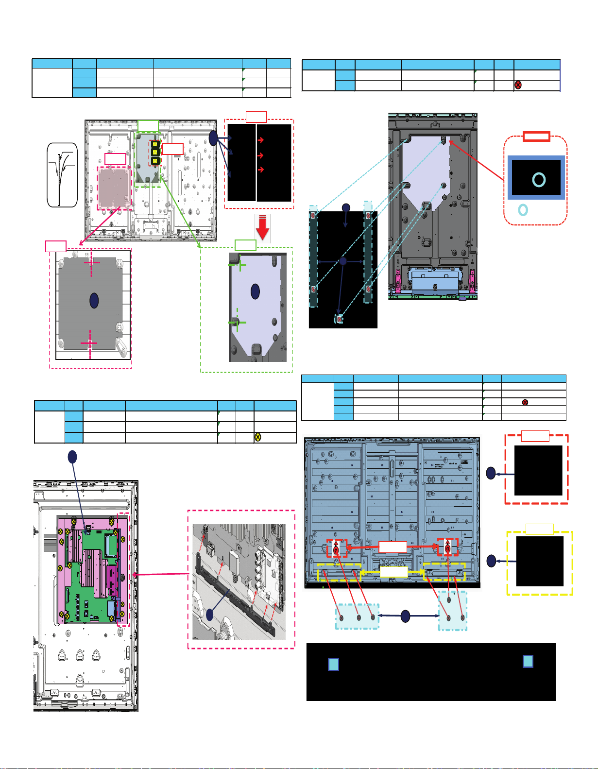
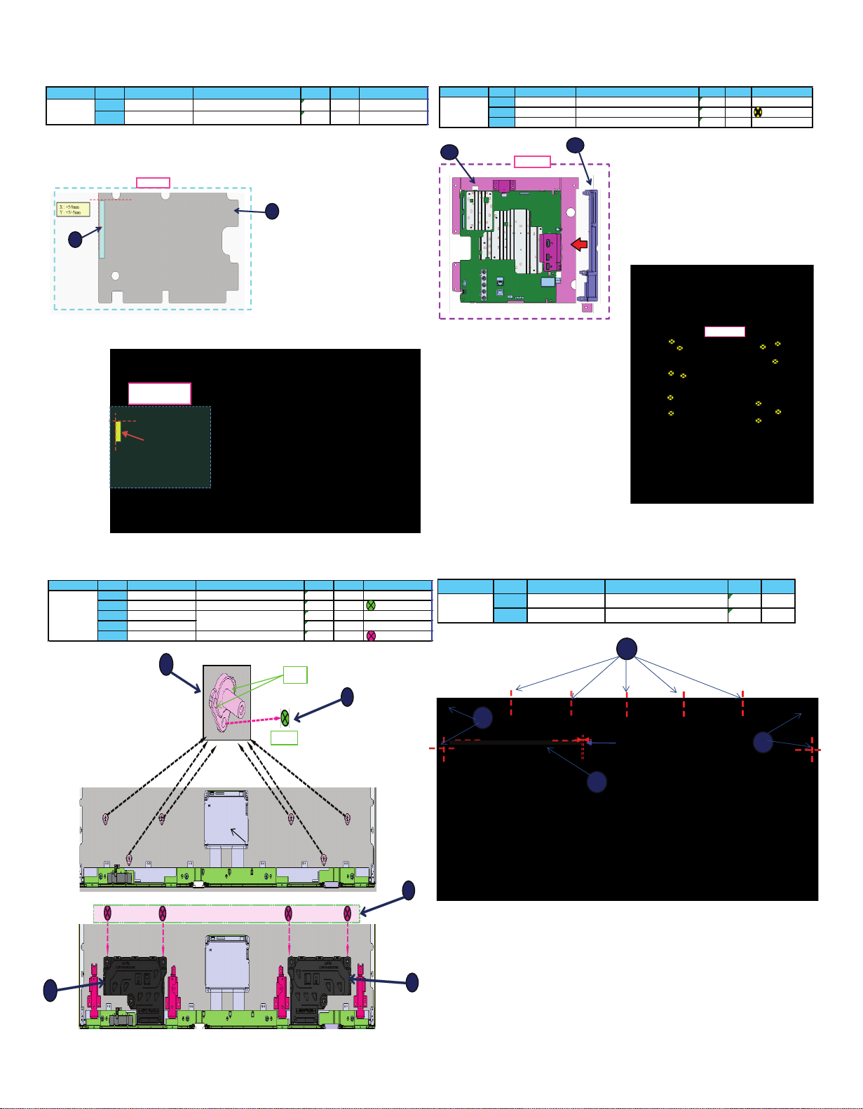
11.7 P-PCB & PB-PCB Barrier.
11.9 PCB A (Main board)
11.8 PCB PB
11.10 Speakers & SP Bracket
TC-65DX800C
TMK5ZX193
PB-PCB_BARRIER
3
TSCNZ0010004
FFC
TMK5ZX143
P-PCB_BARRER
PCE
1
PCE
3
PCE
Unit
Model
No.
Part number
Description
Qty.
1
1
2
barrier
protector
peel off the
protector
adhesive
Detail B
Detail A
Detail A
Detail C
Detail B
Detail C
3
2
1
1
Pin guide
Detalle A
2
Remarks
PCE
Unit
1
TZRNP02XMVE
SKD PLACA PB
1
PCE
TC-65DX800C
2
THEJ036J
SCREW M3
5
Model
No.
Part number
Description
Qty.
1
2
Detail A
1
Detail B
Detail A
Detail B
2
3
5
L0EYAA000071
SPEAKER_R
1
PCE
4
L0EYAA000070
SPEAKER_L
1
PCE
TC-65DX800C
SP_BRACKET_UPPER
2
PCE
3
THEJ036J
M3 SCREW(A5/P7)
6
PCE
Remarks
1
TKP5ZA53101
SP_BRACKET_LOWER
4
PCE
2
TKP5ZA52801
Model
No.
Part number
Description
Qty.
Unit
4
5
PCE
TC-65DX800C
TXN/A1EWVU
3
THEJ036J
M3 SCREW(A5/P7)
14
SIDE AV BRACKET-50C1-NONCI 1LINE
1
PCE
2
PCB A COMPLETE
1
PCE
Remarks
1
TKP5ZA63804
Model
No.
Part number
Description
Qty.
Unit
Detail A
17
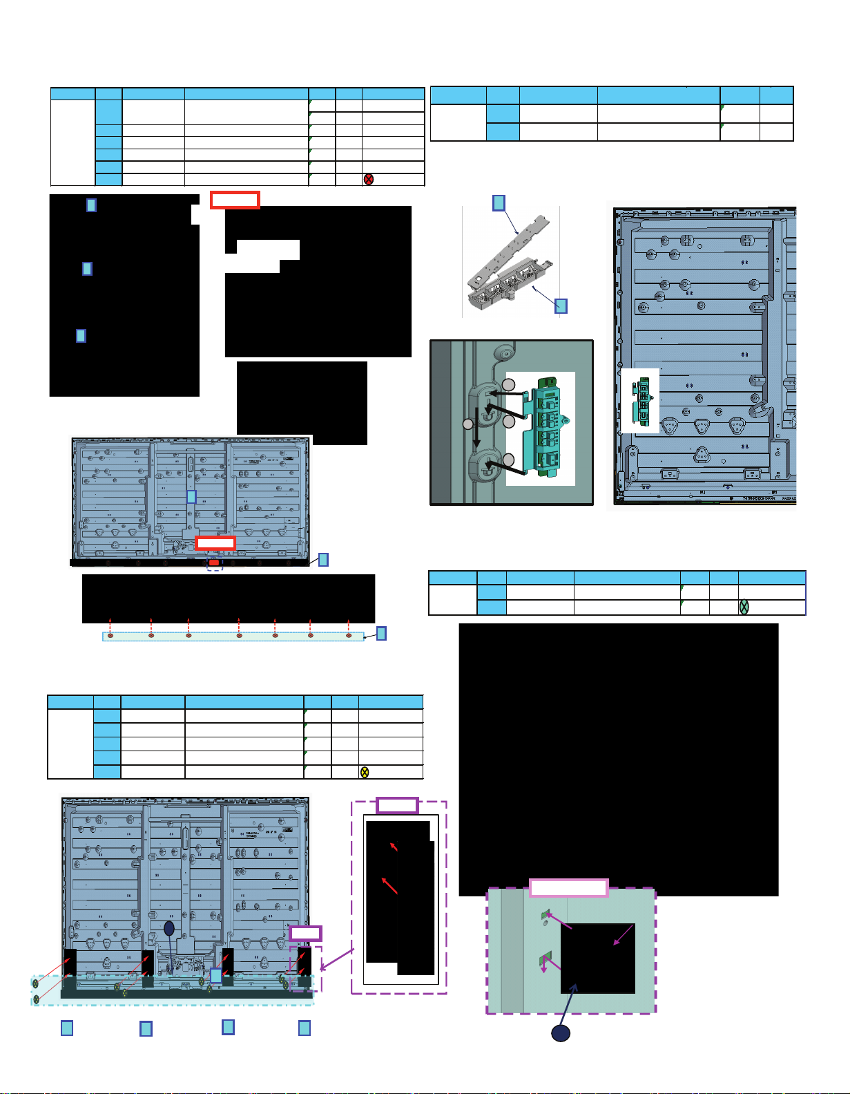
11.11. PCB K
1
3
11.13 Bottom Metal
1. Remove the screws.
2. Remove the 4 Bottom Metals..
11.12 PCB GK
2
1
1
3
2
1
TC-65DX800C
Model
No.
Part number
Description
Qty.
Unit
1
TBX5ZA03301
KEY BUTTON BRACKET
1
PCE
2
TZRNP12WYUA
PCB GK COMPLETE
1
PCE
5
XYN4+J6FJ
SCREW
8
PCE
4
TUX5ZX1281
BOTTOM_METAL-LEFT-65
1
PCE
BOTTOM_METAL-CENTER-RIGHT-65
1
PCE
3
TUX5ZX1331
BOTTOM_METAL-CENTER-LEFT-65
1
PCE
Remarks
TC-65DX800C
1
TUX5ZX1291
BOTTOM_METAL-RIGHT-65
1
PCE
2
TUX5ZX1341
Model
No.
Part number
Description
Qty.
Unit
Detail A
Detail A
5
1
2
4
4
3
Remarks
6
THEJ036J
M3 SCREW(A5/P7)
7
PCE
5
TXFKP5Z0305
BOTTOM_ORNAMENT_ASSY-C2_HS
1
PCE
TKP5ZA53601
LED PANEL CASE
1
PCE
4
TZLP838XMVE
LCD PANEL ASSY
1
PCE
2
TKK5ZC50581
LED PANEL
1
PCE
3
1
PCB K COMPLETE
1
PCE
TC-65DX800C
TXN/K1BHVU
1
PCE
Model
No.
Part number
Description
Qty.
Unit
2
4
5
6
TC-65DX800C
THEJ061J
SCREW(VESA4/BMT4)
Unit
PCE
Model
No.
Part number
Description
Qty.
Remarks
4
PCE
2
1
TUX5ZX0931
VESA METAL
4
Detail A
1
11.14 Bottom Metal
1. Remove the screws.
2. Remove the 4 vesa Metals.
Detail A
18
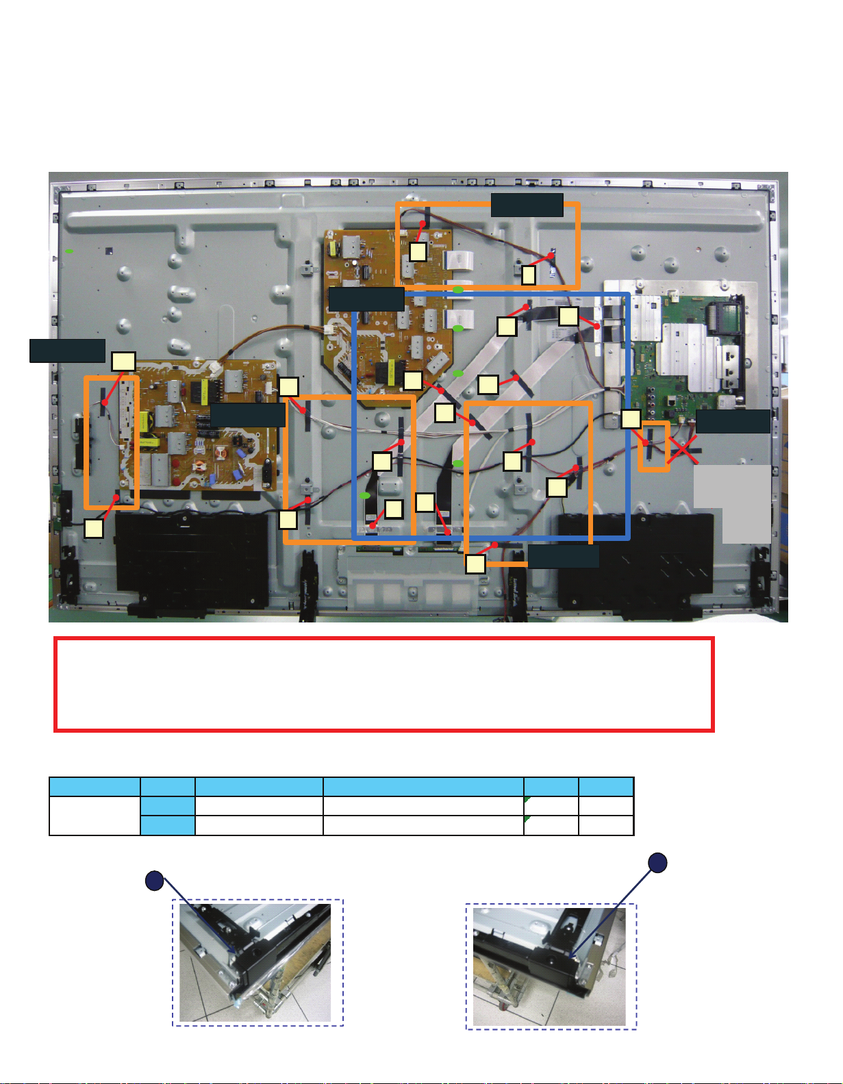
11.15 WIRE DRESSING
11.16 Wires
Clampers
NOTA: Please make sure
to fix A02-Wifi cable
through Speaker as
follow.
6
9
TC-65DX800C
PCE
WIRE(A12-SP)
WIRE(A10-K10/BT)
WIRE(P5-GK4)
8
K1HY05YY0244
WIFI_USB_CABLE
1
PCE
7
TSCKF1050020
FFC_41P
1
PCE
TXJ/P5EWVU
1
PCE
TXJA10EWVU-1
3
1
PCE
TXJA12EWVU
TXJA02EWVU
2
WIRE(P6-PB6)
1
PCE
TXJ/P6EWVU
1
PCE
6
TSCKF1050019
FFC_51P
1
PCE
1
WIRE(A02-PB4/TCOM)
1
Model
No.
Part number
Description
Qty.
Unit
19
11.17 Wire dressing.
11.18 Caution:
Please confirm the correct assembly for wires, also make sure that all connectors are correctly
connected.
DETAIL A
DETAIL B
D
O
A
B
C
DETAIL C
DETAIL E
F
G
E
I
J
N
K
H
DETAIL C
P
Q
R
S
T
DETAIL D
A,-C,.F-Q : PET TAPE: T4FP10050 or T4FP1005J L=60mm, W=10mm (QTY: 13)
D,E : PET TAPE :T4FP10050 L=110mm, W=10mm (QTY: 2 )
Panel screw : PET TAPE: T4FP10050 or T4FP1005J L=60mm, W=10mm (QTY: 5)
R : PET_AL_Tape : TEWF480 (QTY: 1)
R : PET_AL_Tape : TEWF48 (QTY: 2)
BTM_CORNER_COVER_R-65
1
PCE
TC-65DX800C
1
TKP5ZA64501
BTM_CORNER_COVER_L-65
1
PCE
2
TKP5ZA64601
Model
No.
Part number
Description
Qty.
Unit
2
1
11.19 Disassemble bottom corner.
20
12 Assembly and disassembly instructions TC-58DX800C.
12.3 Disassemble AC Inlet
1. Remove the screws
2. Remove the cover.
12.4 Back cover
12.5. WIFI unit
1. Remove the screws.
2. Remove the PCB bracket.
4. Remove Bottom back cover.
12.6 PCB P Power board
1. Disconnect connectors.
2. Remove the 6 screws (THEJ036J).
3. Remove the PCB P.
12.1. Procedure disassembly of the unit.
12.2 Disassembling Pedestal
1. Remove the 4 screws (M4x12).
2. Remove the pedestal
A, B,C,D (KIT)
R
F
1
1
2
2
A
D
A
C
F
E
B
G
TC-58DX800C
4
TBL5ZX11001
PEDESTAL_COVER_ASSY-50W2
1
PCE
3
TBL5ZX10991
STAND_METAL_ASSY-50W2
1
PCE
2
TBL5ZX11191
PEDESTAL_ASSY_R-58N1
1
PCE
1
TBL5ZX11181
PEDESTAL_ASSY_L-58N1
1
PCE
Remarks
Model
No.
Part number
Description
Qty.
Unit
G
1
TKP5ZA63401
CABLE COVER(AC INLET)-50DX700
1
PCE
TC-58DX800C
Model
No.
Part number
Description
Qty.
Unit
2
1
1
1
1
1
1
1
1
1
1
1
2
2
2
2
2
2
2
2
3
3
3
3
4
4
4
4
4
4
4
444
4
4
4
5
1
THTD037J
SCREW(SP4/CTRL1/AV3)
8
PCE
TC-58DX800C
2
THEC1509
SCREW
8
PCE
3
THE5ZC036J
SCREW M6
4
PCE
4
THEC259J
SCREW_M3_STEP
13
PCE
5
TKU5ZC13402
BACK_COVER
1
PCE
Remarks
Model
No.
Part number
Description
Qty.
Unit
1
Make sure that hooks are correctly
assembled
Hooks
Hooks
Pin guide
Detail B
2
2
N5HBZ0000114
WIFI_MODULE
1
PCE
TC-58DX800C
1
TBX5ZA03901
KEY_BUTTON_BRACKET-50C1
1
PCE
Model
No.
Part number
Description
Qty.
Unit
1
TC-58DX800C
2
THEJ036J
M3 SCREW(A5/P7)
7
PCE
Remarks
TZRNP11UQUS
SKD PLACA P
1
PCE
Model
No.
Part number
Description
Qty.
Unit
2
THEJ036J
M3 SCREW(A5/P7)
4
PCE
BOTTOM ORNAMENT_ASSY-58DX7 00
1
PCE
Remarks
TC 58D X8 00C
1
TXFKP5Z03 01
Model
No.
Part number
Description
Qty.
Unit
21
12.7 P-PCB Barrier.
12.9 Speakers & SP Bracket
12.8 PCB A
12.10 Sponge
Detalle A
2
1
Detalle A
TC-58DX800C
Model
2
TMK4GA140
FELT(0.9*130*10)
1
PCE
Unit
No.
Part number
Description
Qty.
Remarks
1
TMK5ZX186
P-PCB_BARRIER
1
PCE
M3 SCREW(A5/P7)
13
PCE
3
TKP5ZA63804
SIDE AV BRACKET
1
PCE
Remarks
TC-58DX800C
1
TXN/A1EXVU
PCB A COMPLETE
1
PCE
2
THEJ036J
Model
No.
Part number
Description
Qty
Unit
Detail A
Detail A
1
3
L0EYAA000090
1
PCE
LOUDSPEAKER SYSTEMS
L0EYAA000089
1
PCE
M3 SCREW(A5/P7)
6
PCE
5
THTF020J
SCREW(SP2)
4
PCE
3
Model
No.
Part number
Description
Qty.
Remarks
Unit
1
TKP5ZA63501
TC-58DX800C
4
2
THEJ036J
SP BRACKET-DX700
6
Pin
screw
2
1
5
4
3
SPONGE(T5X20X20)
9
Modelo
No.
1
TMK4GG127
TC-58DX800C
1
PCE
Número de Parte
Descripción
Cant.
PCE
Unidad
2
TMK4GG129
SPONGE(T5X445X5)
2 ~ 4 mm
1
1
1
2
22
12.11. LCD PANEL & PCB K
12.13 bottom Metal
1. Remove the screws.
2. Remove the Bottom Metals.
12.12 PCB GK
2
TODOS
THEJ061J
SCREW(VESA4/BMT4)
Unit
PCE
Model
No.
Part number
Description
Qty.
Remarks
4
PCE
2
1
TUX5ZX0931
VESA METAL
4
12.14 Bottom Metal
1. Remove the screws.
2. Remove the 4 vesa Metals.
Detail A
TC-58DX800C
4
TKP5ZA62701
BT BRACKET-DX800
1
PCE
5
L5EDDYY008 36
LCD PANEL COMPLETE
1
PCE
PCE
3
TKP5ZA53601
LED PANEL CASE
1
PCE
1
TXN/K1EXVU
PCB K COMPLETE
1
PCE
2
TKK5ZC50602
LED PANEL
1
Model
No.
Part number
Description
Qty.
Unit
Detail A
Detail A
Detail A
1
Detail A
TC-58DX800C
1
TBX5ZA03901
KEY_BUTTON_BRACKET-50C1
1
PCE
Model
No.
Part number
Description
Qty.
Unit
5
1
2
3
4
5
5
THEJ024
TORNILLO METALES
12
PCE
4
TUX5ZX1231
BOTTOM METAL-LEFT
1
PCE
BOTTOM_METAL-RIGHT-58
1
PCE
3
TUX5ZX1301
BOTTOM_METAL-LEFT-58
1
PCE
Remarks
TC-58DX800C
1
TUX5ZX1241
BOTTOM METAL-RIGHT
1
PCE
2
TUX5ZX1311
Model
No.
Part number
Description
Qty
Unit
4
Make sure to clamp
correctly the Control panel
23
12.15 Wire dressing
1. Fix all wire connector and LVDS wire to PCB.
2. Dressing wire follow picture.
3. Stick pet tape for wire dressing.
Note:
Please put A10-K10 true
left speakcer
6
3
1
2
4
5
NG
7
6
PCE
K2CA2YY00332
K1HY05YY0269
WIFI USB CABLE
1
7
PLUGS WITH CABLE FOR AC POWER SOURCE
1
PCE
4
Wire (A02-P2 / TCOM)
PCE
5
TXJA10EXVU-1
2
TSCKF1050018
FFC_41P
1
PCE
PCE
1
FFC_51P
1
PCE
3
TXJA12EXVU
WIRE(A12-SP)
1
A10-K10 WIRE
1
TSCKF1050017
No.
Part number
Description
Qty.
Unit
TXJA02EXVU-1
1
PCE
TC-58DX800C
Model
24
12.16 Wire dressing
1. Fix all wire connector and LVDS wire to PCB.
2. Dressing wire follow picture.
3. Stick pet tape for wire dressing.
*For EMC specification. Please refer EMC specification file of each model.
DETAIL A
A
DETAIL B
B
D
C
F
E
I
JK
DETAIL D
A-H : PET TAPE: T4FP10050 or T4FP1005J L=60mm, W=10mm (QTY: 6)
L : PET TAPE :T4FP10050 L=110mm, W=10mm (QTY: 1 )
I : PET_AL_Tape : TEWF480 (QTY: 1 )
J,K : PET_AL_Tape : TEWF481 (QTY: 2 )
L
25
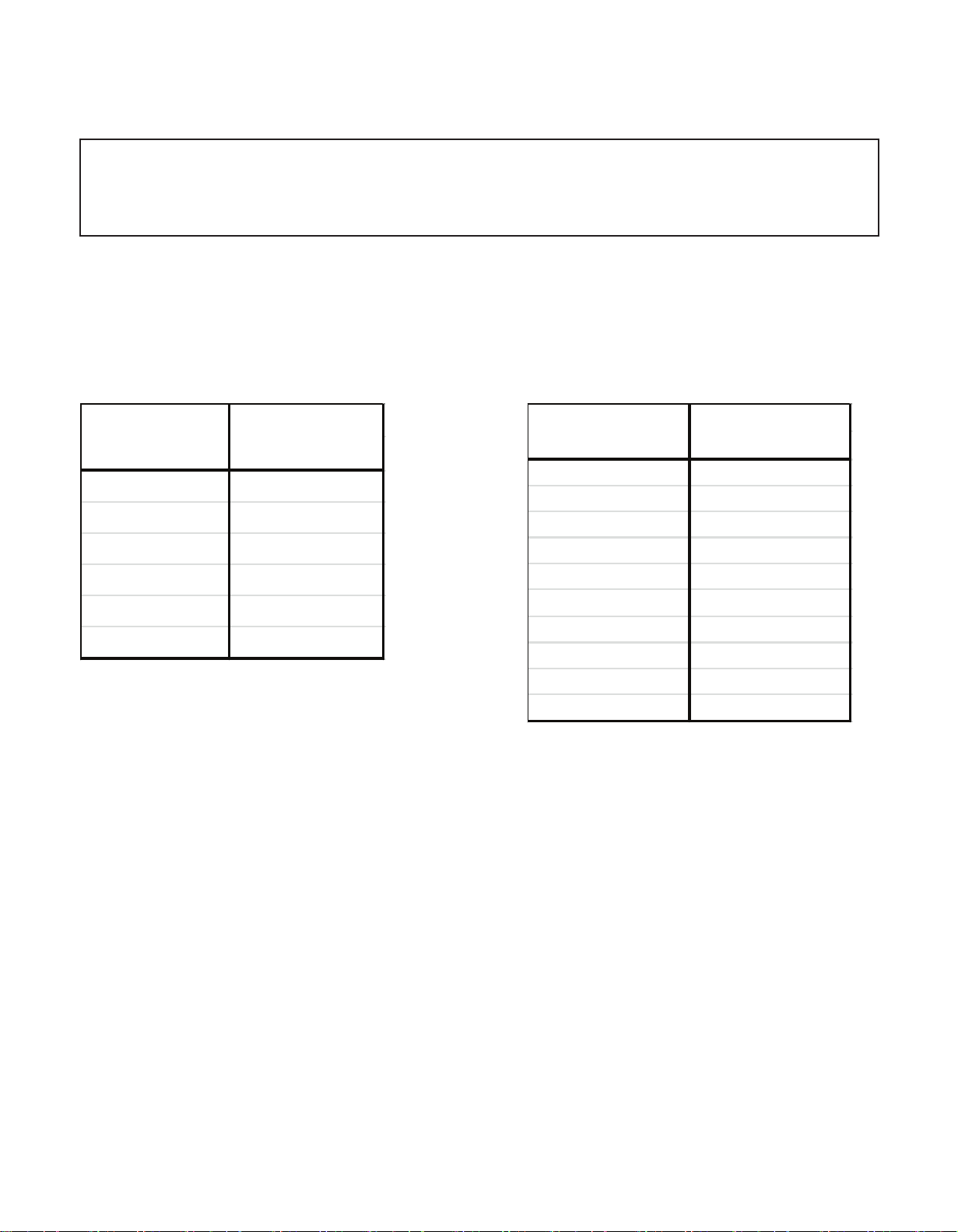
13 Part list remplacement
Important Safety Notice
The components identified by mark have important special features for security. When replacing any
of these components, use the parts specified by the manufacturer.
1. Resistor
Example:
ERD25J104T C 100K , J, 1/4W
Type Allowance
2. Capacitor
Example:
ECKF1H103ZF C 0.01MF, Z, 50V
Type Allowance
Ω
C : Carbon F : ± 1%
F : Fuse G : ± 2%
M : Metal Oxide J : ± 5%
Metal Film K : ± 10%
S: Solid M : ± 20%
W: Wire Wound
Type
Allowance
C : Ceramic C : ± 0.25pF
E : Electrolic D : ± 0.5pF
P : Poliester F : ± 1pF
Polyprop G : ± 3pF
Lene J : ± 5pF
T : Tantalum K : ± 10pF
L : ± 15pF
M : ± 20pF
P : + 100%, -0%
Z : + 80% -20%
Type
Allowance

13.1 PART LIST FOR MAIN BOARD
Only TC-58DX800C model (TXN/A1EXVU)
Note Please be careful in the selection of parts, the differences are described in red, all else being equal.
CAPACITORS
Position Quantity Key Description Comments C3808 1 F1J1E105A287 Chip capacitors
C2000 1 F1G1H102A830 Chip capac itors C3809 1 F1J1E105A287 Chip capacitors
C2001 1 F1G1E103A144 Chip capacitors C3812 1 F1H1E105A153 Chip capacitors
C2002 1 F1G1E103A144 Chip capacitors C3813 1 F1J1E224A272 Chip capacit ors
C2003 1 F1K1E106A167 Chip c apacitors C3814 1 F1H1E104A161 Chip capacitors
C2005 1 F1G1H102A830 Chip capac itors C3815 1 F1H1E104A161 Chip capacitors
C2006 1 F1G1C104A146 Chip capac itors C3816 1 F1J1E224A272 Chip capacitors
C2008 1 F1G1H102A830 Chip capac itors C3817 1 F1H1E104A161 Chip capacitors
C2010 1 F1G1H102A830 Chip capac itors C3818 1 F1H1E104A161 Chip capacitors
C2011 1 F1G1H102A830 Chip capac itors C4030 1 F1G1C104A146 Chip capacitors
C2021 1 F1G1H221A834 Chip capac itors C4031 1 F1G1C104A146 Chip capacitors
C2022 1 F1G1H221A834 Chip capac itors C4032 1 F1G1C104A146 Chip capacitors
C2023 1 F1G1H221A834 Chip capac itors C4033 1 F1G1C104A146 Chip capacitors
C2024 1 F1G1H221A834 Chip capac itors C4034 1 F1G1C104A146 Chip capacitors
C2056 1 F1G1E103A144 Chip capacitors C4035 1 F1G1C104A146 Chip capac itors
C2057 1 F1G1E103A144 Chip capacitors C4036 1 F1G1C104A146 Chip capac itors
C2112 1 F1G1E103A144 Chip capacitors C4037 1 F1G1C104A146 Chip capac itors
C2113 1 F1G1E103A144 Chip capacitors C4038 1 F1G1C104A146 Chip capac itors
C2114 1 F1G1E103A144 Chip capacitors C4039 1 F1G1C104A146 Chip capac itors
C2253 1 F1G1A105A047 Chip capacitors C4040 1 F1G1C104A146 Chip capac itors
C2257 1 F1G1E103A144 Chip capacitors C4041 1 F1G1C104A146 Chip capac itors
C2258 1 F1G1E103A144 Chip capacitors C4042 1 F1G1C104A146 Chip capac itors
C3109 1 F1G1H100A963 Chip capac itors C4043 1 F1G1C104A146 Chip capacitors
C3110 1 F1G1H100A963 Chip capac itors C4044 1 F1G1C104A146 Chip capacitors
C3111 1 F1G1H100A963 Chip capac itors C4045 1 F1G1C104A146 Chip capacitors
C3112 1 F1G1H152A946 Chip capac itors C4050 1 F1G1C104A146 Chip capacitors
C3113 1 F1G1C103A173 Chip capac itors C4051 1 F1G1C104A146 Chip capacitors
C3114 1 F1G1C103A173 Chip capac itors C4052 1 F1G1C104A146 Chip capacitors
C3115 1 F1G1C103A173 Chip capac itors C4053 1 F1G1C104A146 Chip capacitors
C3116 1 F1G1C103A173 Chip capac itors C4054 1 F1G1C104A146 Chip capacitors
C3124 1 F1G1A105A047 Chip capacitors C4055 1 F1G1C104A146 Chip capac itors
C3125 1 F1G1A105A047 Chip capacitors C4056 1 F1G1C104A146 Chip capac itors
C3127 1 F1G1A473A079 Chip capacitors C4057 1 F1G1C104A146 Chip capac itors
C3163 1 F1G1H101A948 Chip capac itors C4058 1 F1G1C104A146 Chip capacitors
C3164 1 F1G1H101A948 Chip capac itors C4059 1 F1G1C104A146 Chip capacitors
C3200 1 F1G1C104A146 Chip capac itors C4060 1 F1G1C104A146 Chip capacitors
C3801 1 F1K1E106A167 Chip c apacitors C4061 1 F1G1C104A146 Chip capacitors
C3802 1 F1K1E106A167 Chip c apacitors C4062 1 F1G1C104A146 Chip capacitors
C3803 1 F1K1E106A167 Chip c apacitors C4063 1 F1G1C104A146 Chip capacitors
C3806 1 F1J1E105A287 Chip capacit ors C4064 1 F1G1C104A146 Chip capacitors
C3807 1 F1J1E105A287 Chip capacit ors C4065 1 F1G1C104A146 Chip capacitors
Position Quantity Key Description Comments
26

13.1 PART LIST FOR MAIN BOARD
Only TC-58DX800C model (TXN/A1EXVU)
Note Please be careful in the selection of parts, the differences are described in red, all else being equal.
C4080 1 F1G1C104A146 Chip capac itors C5144 1 F1H1E105A153 Chip capacitors
C4081 1 F1G1C104A146 Chip capac itors C5202 1 F1K1E106A167 Chip capacitors
C4082 1 F1G1C104A146 Chip capac itors C5203 1 F1H1E104A161 Chip capacitors
C4083 1 F1G1C104A146 Chip capac itors C5204 1 F1J0J2260004 Chip capacitors
C4084 1 F1G1C104A146 Chip capac itors C5205 1 F1J0J2260004 Chip capacitors
C4085 1 F1G1C104A146 Chip capac itors C5207 1 F1G1A105A047 Chip capacitors
C4086 1 F1G1C104A146 Chip capac itors C5208 1 F1G1E822A144 Chip capacitors
C4087 1 F1G1C104A146 Chip capac itors C5209 1 F1G1H100A963 Chip capacitors
C4088 1 F1G1C104A146 Chip capac itors C5210 1 F1G1C104A146 Chip capacitors
C4089 1 F1G1C104A146 Chip capac itors C5212 1 F1G1E103A144 Chip capacitors
C4090 1 F1G1C104A146 Chip capac itors C5221 1 F1K1E106A167 Chip capacitors
C4091 1 F1G1C104A146 Chip capac itors C5222 1 F1H1E104A161 Chip capacitors
C4092 1 F1G1C104A146 Chip capac itors C5223 1 F1J1A106A043 Chip capacitors
C4093 1 F1G1C104A146 Chip capac itors C5224 1 F1J1A106A043 Chip capacitors
C4094 1 F1G1C104A146 Chip capac itors C5225 1 F1J1A106A043 Chip capacitors
C4095 1 F1G1C104A146 Chip capac itors C5226 1 F1J1A106A043 Chip capacitors
C4096 1 F1G1C104A146 Chip capac itors C5228 1 F1G1H222A946 Chip capacitors
C4097 1 F1G1C104A146 Chip capac itors C5229 1 F1G1H680A948 Chip capacitors
C4098 1 F1G1C104A146 Chip capac itors C5230 1 F1G1C104A146 Chip capacitors
C4099 1 F1G1C104A146 Chip capac itors C5260 1 F1K1E106A167 Chip capacitors
C4100 1 F1G1C104A146 Chip capac itors C5261 1 F1K1E106A167 Chip capacitors
C4101 1 F1G1C104A146 Chip capac itors C5262 1 F1H1E104A161 Chip capacitors
C4102 1 F1G1C104A146 Chip capac itors C5263 1 F1G1E103A144 Chip capacitors
C4103 1 F1G1C104A146 Chip capac itors C5264 1 F1G1H472A830 Chip capacitors
C4104 1 F1G1H101A948 Chip capac itors C5265 1 F1G1H681A571 Chip capacitors
C4105 1 F1G1E103A144 Chip capacitors C5266 1 F1G1C104A146 Chip capac itors
C4106 1 F1K1E106A167 Chip c apacitors C5270 1 F1K1E106A167 Chip capacitors
C4120 1 F1G1E103A144 Chip capacitors C5271 1 F1K1E106A167 Chip c apacitors
C4500 1 F1H1E105A153 Chip capacitors C5272 1 F1K1E106A167 Chip capacitors
C4578 1 F1G1A105A047 Chip capacitors C5273 1 F1K1E106A167 Chip c apacitors
C4579 1 F1G1A105A047 Chip capacitors C5717 1 F1J1A106A043 Chip capacit ors
C4599 1 F1G1H101A948 Chip capac itors C5718 1 F1J1A106A043 Chip capacitors
C5020 1 F1G1A105A047 Chip capacitors C5920 1 F1G1C104A146 Chip capac itors
C5022 1 F1G1A105A047 Chip capacitors C6703 1 F1J1A106A043 Chip capacit ors
C5024 1 F1G1A105A047 Chip capacitors C6704 1 F1G1C104A146 Chip capac itors
C5025 1 F1J1E105A287 Chip capacit ors C6705 1 F1J1A 106A043 Chip capacitors
C5026 1 F1G1A105A047 Chip capacitors C6707 1 F1G1C104A146 Chip capac itors
C5029 1 F1H1A225A051 Chip capacitors C6717 1 F1G1H220A834 Chip capacitors
C5030 1 F1G1A105A047 Chip capacitors C6718 1 F1G1H220A834 Chip capac itors
C5031 1 F1G1A105A047 Chip capacitors C6720 1 F1G1H220A834 Chip capac itors
C5032 1 F1H1E105A153 Chip capacitors C6721 1 F1G1H220A834 Chip capacitors
C5105 1 F1G1E103A144 Chip capacitors C6731 1 F1G1H101A948 Chip capac itors
27

13.1 PART LIST FOR MAIN BOARD
Only TC-58DX800C model (TXN/A1EXVU)
Note Please be careful in the selection of parts, the differences are described in red, all else being equal.
C6732 1 F1G1H101A948 Chip capac itors C8025 1 F1G1C104A146 Chip capacitors
C6739 1 F1G1C104A146 Chip capac itors C8026 1 F1G1C104A146 Chip capacitors
C6950 1 F1G0J1050007 Chip capacit ors C8027 1 F1G1C104A146 Chip capacitors
C6953 1 F1G1E103A144 Chip capacitors C8028 1 F1G1A105A047 Chip capacitors
C6954 1 F1G1E103A144 Chip capacitors C8029 1 F1H0J4750004 Chip capacitors
C6957 1 F1G1H181A834 Chip capac itors C8030 1 F1G1C104A146 Chip capacitors
C6958 1 F1G1C104A146 Chip capac itors C8031 1 F1G1C104A146 Chip capacitors
C6959 1 F1G1H181A834 Chip capac itors C8034 1 F1G1C104A146 Chip capacitors
C6960 1 F1G1H472A830 Chip capac itors C8035 1 F1G1A105A047 Chip capacitors
C6961 1 F1G0J1050007 Chip capacit ors C8036 1 F1G1C104A146 Chip capacitors
C6964 1 F1H1H181B052 Chip capacitors C8038 1 F1G1C104A146 Chip capac itors
C6965 1 F1G1C104A146 Chip capac itors C8039 1 F1G1C104A146 Chip capacitors
C6967 1 F1G1H121A834 Chip capac itors C8040 1 F1J0G2260001 Chip capacitors
C6968 1 F1G1H102A830 Chip capac itors C8041 1 F1G1C104A146 Chip capacitors
C6970 1 F1G1H102A830 Chip capac itors C8042 1 F1G1C104A146 Chip capacitors
C6971 1 F1G1H5R0A947 Chip capacitors C8043 1 F1G1C104A146 Chip capacitors
C6973 1 F1G1H5R0A947 Chip capacitors C8044 1 F1G1C104A146 Chip capacitors
C6974 1 F1G1H121A834 Chip capac itors C8045 1 F1G1C104A146 Chip capacitors
C6977 1 F1G1H331A946 Chip capac itors C8046 1 F1H0J4750004 Chip c apacitors
C6982 1 F1G1E103A144 Chip capacitors C8047 1 F1H0J4750004 Chip capacitors
C6988 1 F1G1H102A830 Chip capac itors C8048 1 F1H0J4750004 Chip c apacitors
C8000 1 F1G1C104A146 Chip capac itors C8049 1 F1H0J4750004 Chip c apacitors
C8001 1 F1G1C104A146 Chip capac itors C8050 1 F1G1A105A047 Chip capacitors
C8002 1 F1J1A106A043 Chip capacit ors C8051 1 F1G1C104A146 Chip capacitors
C8003 1 F1G1C104A146 Chip capac itors C8052 1 F1G1A105A047 Chip capacitors
C8004 1 F1G1C104A146 Chip capac itors C8054 1 F1G1C104A146 Chip capacitors
C8005 1 F1G1C104A146 Chip capac itors C8058 1 F1J1A106A043 Chip capacitors
C8006 1 F1G1C104A146 Chip capac itors C8059 1 F1G1A105A047 Chip capacitors
C8007 1 F1G1C104A146 Chip capac itors C8060 1 F1G1C104A146 Chip capacitors
C8008 1 F1G1C104A146 Chip capac itors C8061 1 F1J0G2260001 Chip capacitors
C8009 1 F1J0G2260001 Chip capacit ors C8062 1 F1J0G 2260001 Chip capacitors
C8010 1 F1G1C104A146 Chip capac itors C8100 1 F1G1H222A946 Chip capacitors
C8011 1 F1J0G2260001 Chip capacit ors C8101 1 F1G1C104A146 Chip capacitors
C8012 1 F1H0J4750004 Chip capacitors C8102 1 F1K1E106A167 Chip capacitors
C8014 1 F1G1C104A146 Chip capac itors C8103 1 F1K1E106A167 Chip capacitors
C8015 1 F1G1C104A146 Chip capac itors C8104 1 F1H1E104A161 Chip capacitors
C8016 1 F1J1A106A043 Chip capacit ors C8105 1 F1G1E332A172 Chip capacitors
C8017 1 F1G1C104A146 Chip capac itors C8106 1 F1J0G2260001 Chip capacitors
C8021 1 F1G1A105A047 Chip capacitors C8107 1 F1J0G2260001 Chip capacit ors
C8022 1 F1G1C104A146 Chip capac itors C8108 1 F1J0G2260001 Chip capacitors
C8023 1 F1G1A105A047 Chip capacitors C8109 1 F1H1E105A153 Chip capacitors
C8024 1 F1G1C104A146 Chip capac itors C8110 1 F1J1E475A257 Chip capacitors
28

13.1 PART LIST FOR MAIN BOARD
Only TC-58DX800C model (TXN/A1EXVU)
Note Please be careful in the selection of parts, the differences are described in red, all else being equal.
C8112 1 F1H1E104A161 Chip capacitors C8234 1 F1G1C104A146 Chip capacitors
C8114 1 F1K1E106A167 Chip c apacitors C8235 1 F1G1C104A146 Chip capacitors
C8116 1 F1G1C104A146 Chip capac itors C8236 1 F1G1C104A146 Chip capacitors
C8121 1 F1J0G2260001 Chip capacit ors C8237 1 F1G1E153A144 Chip capacitors
C8122 1 F1J0G2260001 Chip capacit ors C8238 1 F1G1C104A146 Chip capacitors
C8124 1 F1G1A105A047 Chip capacitors C8239 1 F1G1C104A146 Chip capac itors
C8125 1 F1G1A105A047 Chip capacitors C8240 1 F1G1C104A146 Chip capac itors
C8126 1 F1G1C104A146 Chip capac itors C8241 1 F1G1C104A146 Chip capacitors
C8200 1 F1G1E153A144 Chip capacitors C8242 1 F1G1C104A146 Chip capac itors
C8201 1 F1G1C104A146 Chip capac itors C8243 1 F1G1C104A146 Chip capacitors
C8202 1 F1G1C104A146 Chip capac itors C8244 1 F1G1C104A146 Chip capacitors
C8203 1 F1G1C104A146 Chip capac itors C8245 1 F1J1A106A043 Chip capacitors
C8204 1 F1G1C104A146 Chip capac itors C8246 1 F1G1C104A146 Chip capacitors
C8205 1 F1G1C104A146 Chip capac itors C8247 1 F1G1C104A146 Chip capacitors
C8206 1 F1G1C104A146 Chip capac itors C8248 1 F1G1C104A146 Chip capacitors
C8207 1 F1G1C104A146 Chip capac itors C8249 1 F1G1C104A146 Chip capacitors
C8208 1 F1J1A106A043 Chip capacit ors C8250 1 F1G1C104A146 Chip capacitors
C8209 1 F1G1C104A146 Chip capac itors C8251 1 F1G1C104A146 Chip capacitors
C8210 1 F1G1C104A146 Chip capac itors C8252 1 F1G1C104A146 Chip capacitors
C8211 1 F1G1C104A146 Chip capac itors C8253 1 F1G1C104A146 Chip capacitors
C8212 1 F1G1C104A146 Chip capac itors C8254 1 F1G1C104A146 Chip capacitors
C8213 1 F1G1C104A146 Chip capac itors C8255 1 F1G1C104A146 Chip capacitors
C8214 1 F1G1C104A146 Chip capac itors C8256 1 F1J1A106A043 Chip capacitors
C8215 1 F1G1C104A146 Chip capac itors C8257 1 F1G1C104A146 Chip capacitors
C8216 1 F1G1C104A146 Chip capac itors C8258 1 F1G1C104A146 Chip capacitors
C8217 1 F1G1C104A146 Chip capac itors C8259 1 F1G1C104A146 Chip capacitors
C8218 1 F1G1C104A146 Chip capac itors C8260 1 F1G1C104A146 Chip capacitors
C8219 1 F1G1C104A146 Chip capac itors C8261 1 F1G1C104A146 Chip capacitors
C8220 1 F1G1C104A146 Chip capac itors C8262 1 F1G1C104A146 Chip capacitors
C8221 1 F1G1C104A146 Chip capac itors C8263 1 F1G1C104A146 Chip capacitors
C8222 1 F1G1C104A146 Chip capac itors C8264 1 F1G1C104A146 Chip capacitors
C8223 1 F1G1C104A146 Chip capac itors C8265 1 F1G1C104A146 Chip capacitors
C8224 1 F1G1C104A146 Chip capac itors C8266 1 F1G1C104A146 Chip capacitors
C8225 1 F1J1A106A043 Chip capacit ors C8267 1 F1G1C104A146 Chip capacitors
C8226 1 F1G1C104A146 Chip capac itors C8268 1 F1G1C104A146 Chip capacitors
C8227 1 F1G1C104A146 Chip capac itors C8269 1 F1G1E153A144 Chip capacitors
C8228 1 F1G1C104A146 Chip capac itors C8270 1 F1G1C104A146 Chip capacitors
C8229 1 F1G1C104A146 Chip capac itors C8271 1 F1G1C104A146 Chip capacitors
C8230 1 F1G1C104A146 Chip capac itors C8272 1 F1G1C104A146 Chip capacitors
C8231 1 F1G1C104A146 Chip capac itors C8273 1 F1G1C104A146 Chip capacitors
C8232 1 F1G1C104A146 Chip capac itors C8274 1 F1J1H104A902 Chip capacitors
C8233 1 F1G1C104A146 Chip capac itors C8279 1 F1J1A106A043 Chip capacitors
29

13.1 PART LIST FOR MAIN BOARD
Only TC-58DX800C model (TXN/A1EXVU)
Note Please be careful in the selection of parts, the differences are described in red, all else being equal.
C8280 1 F1G1C104A146 Chip capac itors C8812 1 F1G1A105A047 Chip capacitors
C8281 1 F1G1C104A146 Chip capac itors C8921 1 F1G1C104A146 Chip capacitors
C8282 1 F1G1C104A146 Chip capac itors C8923 1 F1J1A106A043 Chip capacitors
C8283 1 F1G1C104A146 Chip capac itors C8924 1 F1J1A106A043 Chip capacitors
C8284 1 F1G1C104A146 Chip capac itors C8925 1 F1G1C104A146 Chip capacitors
C8285 1 F1G1C104A146 Chip capac itors C8926 1 F1G1C104A146 Chip capacitors
C8286 1 F1G1C104A146 Chip capac itors C8927 1 F1G1H100A948 Chip capacitors
C8287 1 F1G1C104A146 Chip capac itors C8928 1 F1H1E105A153 Chip capacitors
C8288 1 F1G1C104A146 Chip capac itors C9000 1 F1J1A106A043 Chip capacitors
C8289 1 F1G1C104A146 Chip capac itors C9001 1 F1G1A105A047 Chip capacitors
C8290 1 F1G1C104A146 Chip capac itors C9002 1 F1G1A105A047 Chip capacitors
C8295 1 F1G1C104A146 Chip capac itors C9003 1 F1G1C104A146 Chip capacitors
C8300 1 F1G1H8R0A963 Chip capacitors C9004 1 F1G1C104A146 Chip capacitors
C8301 1 F1G1H8R0A963 Chip capacitors C9005 1 F1J1A106A043 Chip capacitors
C8359 1 F1G1C104A146 Chip capac itors C9006 1 F1G1C104A146 Chip capacitors
C8601 1 F1G1C103A173 Chip capac itors C9007 1 F1G1A105A047 Chip capacitors
C8604 1 F1G1C103A173 Chip capac itors C9008 1 F1G1A105A047 Chip capacitors
C8610 1 F1G1A105A047 Chip capacitors C9009 1 F1G1C104A146 Chip capac itors
C8611 1 F1G1A105A047 Chip capacitors C9010 1 F1G1C104A146 Chip capac itors
C8701 1 F1J1A106A043 Chip capacit ors C9016 1 F1G1C104A146 Chip capacitors
C8702 1 F1G1C104A146 Chip capac itors C9017 1 F1G1C104A146 Chip capacitors
C8703 1 F1J1A106A043 Chip capacit ors C9018 1 F1G1C104A146 Chip capacitors
C8704 1 F1J1A106A043 Chip capacit ors C9019 1 F1G1C104A146 Chip capacitors
C8705 1 F1G1C104A146 Chip capac itors C9020 1 F1J1A106A043 Chip capacitors
C8706 1 F1J1A106A043 Chip capacit ors C9021 1 F1G1C104A146 Chip capacitors
C8707 1 F1G1C104A146 Chip capac itors C9022 1 F1G1C104A146 Chip capacitors
C8708 1 F1J1A106A043 Chip capacit ors C9023 1 F1G1C104A146 Chip capacitors
C8709 1 F1J1A106A043 Chip capacit ors C9024 1 F1G1C104A146 Chip capacitors
C8710 1 F1G1C104A146 Chip capac itors C9030 1 F1J1A106A043 Chip capacitors
C8712 1 F1G1C104A146 Chip capac itors C9032 1 F1G1C104A146 Chip capacitors
C8713 1 F1G1C104A146 Chip capac itors C9033 1 F1G1C104A146 Chip capacitors
C8714 1 F1J1A106A043 Chip capacit ors C9034 1 F1G1C104A146 Chip capacitors
C8715 1 F1G1C104A146 Chip capac itors C9036 1 F1G1C104A146 Chip capacitors
C8717 1 F1J1A106A043 Chip capacit ors C9037 1 F1G1C104A146 Chip capacitors
C8718 1 F1J1A106A043 Chip capacit ors C9038 1 F1G1C104A146 Chip capacitors
C8719 1 F1G1C104A146 Chip capac itors C9040 1 F1G1C104A146 Chip capacitors
C8739 1 F1J1A106A043 Chip capacit ors C9041 1 F1J1A 106A043 Chip capacitors
C8740 1 F1G1C104A146 Chip capac itors C9042 1 F1J1A106A043 Chip capacitors
C8742 1 F1J1A106A043 Chip capacit ors C9043 1 F1G1C104A146 Chip capacitors
C8744 1 F1J1A106A043 Chip capacit ors C9045 1 F1J1A 106A043 Chip capacitors
C8745 1 F1G1C104A146 Chip capac itors C9046 1 F1G1C104A146 Chip capacitors
C8811 1 F1G1C104A146 Chip capac itors C9047 1 F1G1C104A146 Chip capacitors
30
 Loading...