

Panasonic TX-51P15X, TC-51P15H, TC-51P15G, TX-51P15H User Manual
Projection Television
Operating Instructions
Model No.
TC-51P15 Series
X
-51P15 Series
T
This is a combined Operating Instruction
manual for all the above series of models.
Please read these instructions before
operating your set and retain them for
future reference.
TQBC0191-2

1

Dear Panasonic Customer
Welcome to the Panasonic family of customers. We hope that you will have many
years of enjoyment from your new colour television set.
To obtain maximum benefit from your set, please read these Instructions
before making any adjustments, and retain them for future reference.
Retain your purchase receipt also, and note down the Model Number and
Serial Number of your set in the space provided on the rear cover of these
Instructions.
Important Information
(1) The long time (max. 2 hours) use of TV game on the set is not recommended since the signal from
TV game may be the cause of damage on picture projection tubes on the set.
(2) Do not allow a still picture to be displayed for an extended period, as this can cause a permanent
after-image to remain on the Projection TV screen.
Examples of still pictures include logos, video games, computer images, teletext and images
displayed in 16 : 9 mode.
If still picture cannot be avoided, reduce the brightness and contrast levels of the picture to minimize
any damage that might occur.
(3) In order to minimize any damage to the projection tubes, this set uses the PICTURE SHIFT
function (Refer to page 46) to change (shift) the entire picture approximately 4 mm every 30
minutes.
2

Table of Contents
Warnings and Cautions 4 ~ 5
Before Operating This Set 6 ~ 9
How to Use This Manual ...................................................................................................................................................... 6
Quick Reference Guide for your TV Set .............................................................................................................................. 7
Securing the casters ............................................................................................................................................................ 7
Connecting the Aerial Cable to the RF In Terminal ............................................................................................................. 8
Safety Precaution ................................................................................................................................................................ 8
Connecting the Plug to the wall Outlet ................................................................................................................................. 9
How to Turn the Power On .................................................................................................................................................. 9
Battery Installation ............................................................................................................................................................... 9
Convergence Adjustment 10 ~ 11
Location of Controls 12 ~ 14
Connections 15 ~ 17
Flow Chart of Main menu 18 ~ 19
Tuning Procedure 20 ~ 31
Channel Selection .............................................................................................................................................................. 20
Regional System Selection ................................................................................................................................................ 22
Channel Allocation ............................................................................................................................................................. 23
Automatic Tune .................................................................................................................................................................. 24
Manual Tune ...................................................................................................................................................................... 26
Fine Tuning ........................................................................................................................................................................ 28
How to Cancel the Fine Tuning.......................................................................................................................................... 29
Programme Number Skip .................................................................................................................................................. 30
How to Cancel the Skip Function ....................................................................................................................................... 31
General Operation 32 ~ 35
How to switch the power ON or OFF / STANDBY mode ................................................................................................... 32
Programme Number Selection .......................................................................................................................................... 32
Direct Programme Number Selection ................................................................................................................................ 32
Volume adjustment ............................................................................................................................................................ 32
TV / AV mode Selection / Display button / Game button / Sound Mute button / Recall button / Off Timer button ............. 33
Sound System Selection .................................................................................................................................................... 34
Colour System Selection ................................................................................................................................................... 35
Advanced Remote Control Operation 36 ~ 41
PICTURE IN PICTURE Operation ..................................................................................................................................... 36
STROBE, CH SEARCH and STILL Operation .................................................................................................................. 38
P.AI and D.PNR Operation ................................................................................................................................................ 39
Surround Operation ........................................................................................................................................................... 40
Stereo Reception ............................................................................................................................................................... 41
Main Menu Operation 42 ~ 49
Picture Menu Operation ..................................................................................................................................................... 42
Sound Menu Operation ...................................................................................................................................................... 43
Features Menu Operation .................................................................................................................................................. 44
Language Menu Operation ................................................................................................................................................ 47
Multi PIP Menu Operation .................................................................................................................................................. 48
Teletext Operation (For TX-51P15 series) 50 ~ 53
Operation of the VCR / LD / DVD 54 ~ 55
Troubleshooting 56
Cleaning 57
Specifications 58 ~ 59
3
Warnings and Cautions
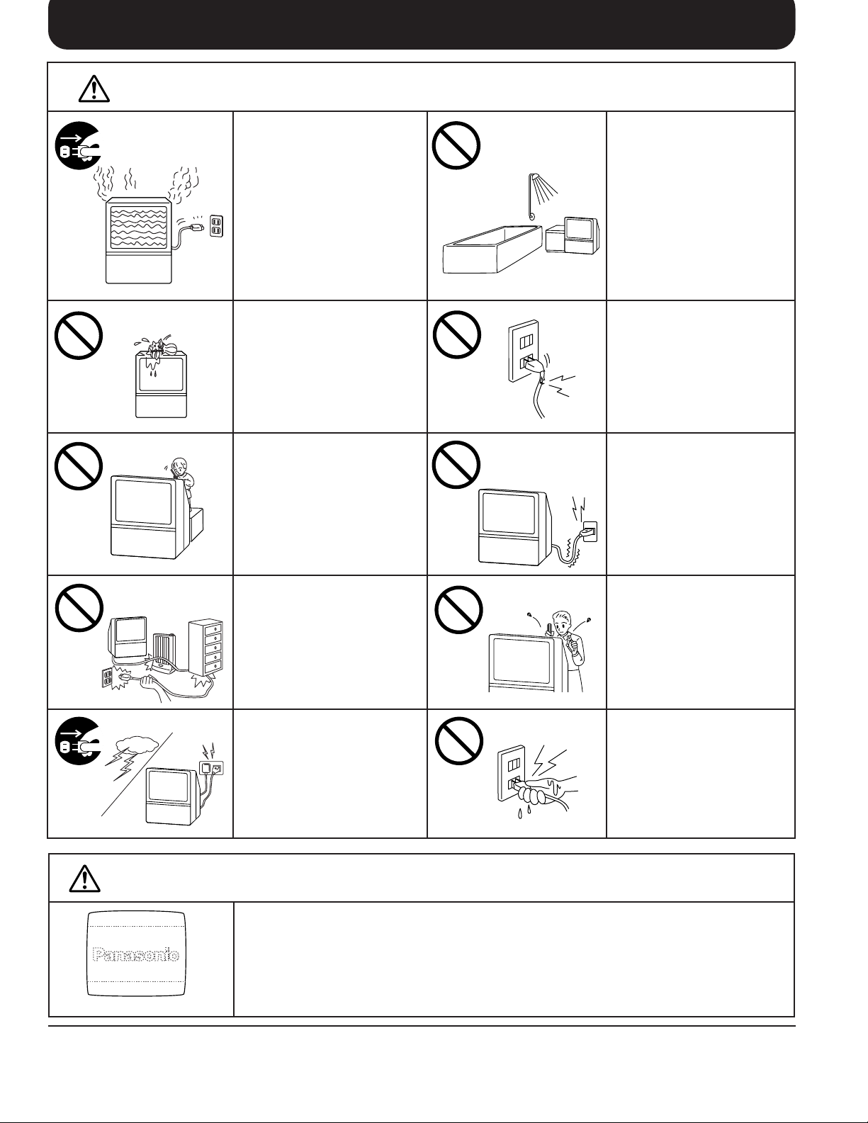
Warnings
Unplug the power cord in the
event of any malfunction
(screen goes blank, no sound,
odd sounds, smoke or unusual
odors coming from the unit).
Unplug the power cord if
foreign matter or water falls
into the unit, or if the unit is
dropped or the cabinet is
damaged.
DO NOT place any of the
following on the unit:
Flower vases, flower pots,
cups, small metal objects, or
cosmetics containers,
chemicals or water.
DO NOT insert foreign objects
(metal or easily flammable
objects).
DO NOT use this unit near
water. (Near a bath tub, etc.)
DO NOT use if the power cord
or power plug is damaged, or
if the plug does not fit tightly
into the socket.
DO NOT use at a voltage other
than indicated
Cautions
TAKE CARE NOT to damage
the power cord.
DO NOT touch the aerial cable
and this unit when there is
lightning.
Do not allow a still picture to be displayed for an extended period, as this can cause a permanent
after-image to remain on the Projection TV screen.
Examples of still pictures include logos, video games, computer images, teletext and images
displayed in 16 : 9 mode.
DO NOT remove the rear
cover as live parts and High
Voltage components are
accessible when the rear
cover is removed.
DO NOT touch the power plug
if your hands are wet.
afterimages appear
4
Warnings and Cautions
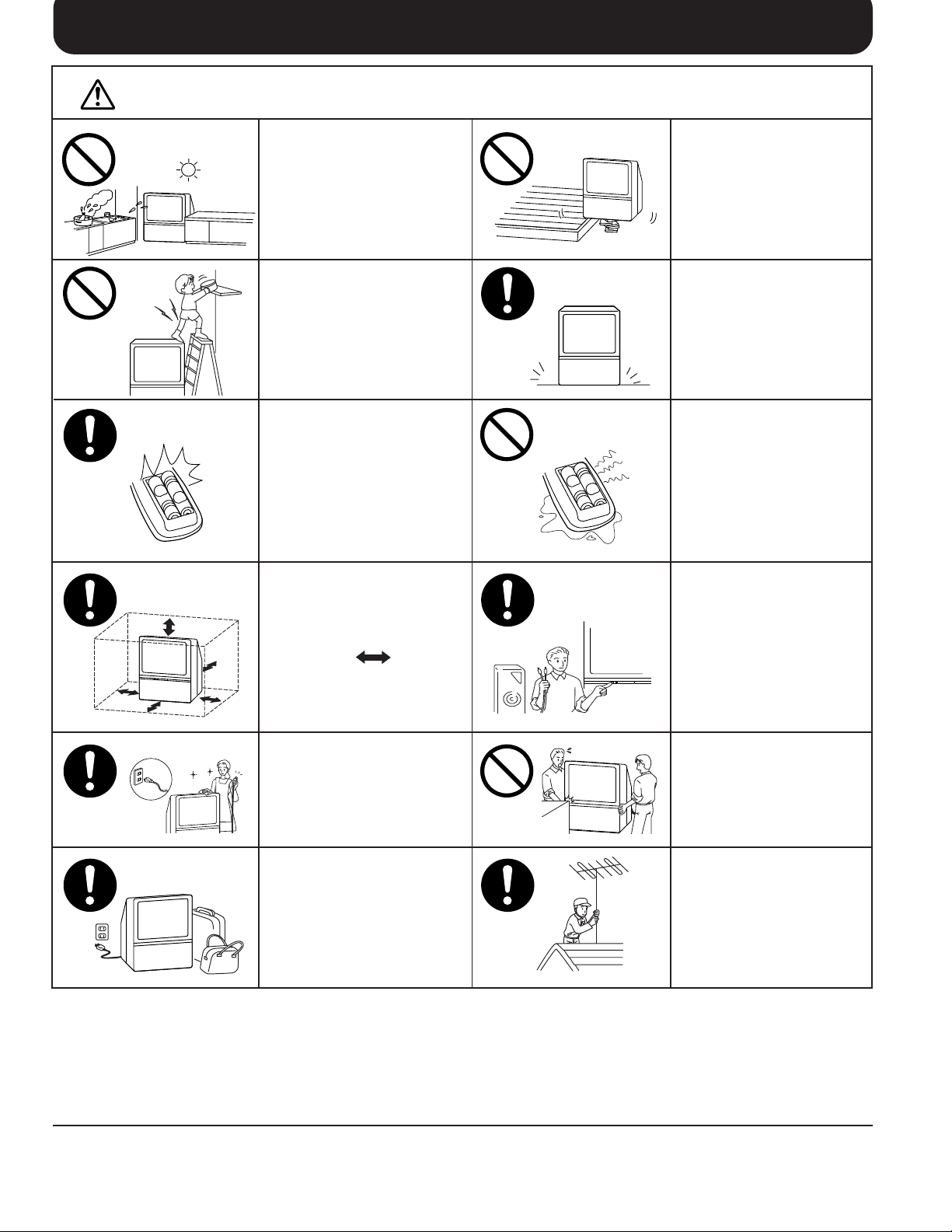
Cautions
DO NOT place in humid or
dusty location, or areas
exposed to smoke or steam.
DO NOT place in direct
sunlight and other sources
of direct heat.
DO NOT stand, or place heavy
objects on the unit.
Particular care should be taken
by families with small children.
When inserting batteries,
ensure that the polarities
(positive and negative) are
correctly aligned. Insert as
shown on remote control. If
inserted incorrectly, battery
fluid may leak, and fire, injury,
or damage to surrounding
components may result.
Adequate ventilation is
essential to prevent failure of
electrical components, we
recommend that a gap of at
least 10 cm ( ) is left all
around this unit even when it
is placed inside a cabinet or
between shelves.
DO NOT place in an unstable
location
Place in a safe location.
Do not mix new and old
batteries. Use only the
specified batteries. Failure to
follow this precaution may
result in leakage of battery
fluid. Fire, injury, or damage
to surrounding components
may also result.
Turn the power “Off” before
connecting other electrical
equipment.
Before cleaning, unplug the
power plug from the socket.
Unplug the power plug from the
socket if you are not going to
use the unit for an extended
period.
DO NOT joint the unit.
Ask your sales outlet to install
the aerial.
To ensure continued excellent performance by this product, periodic cleaning is recommended. See page 57 for more
information.
5
Before Operating This Set
How to Use This Manual
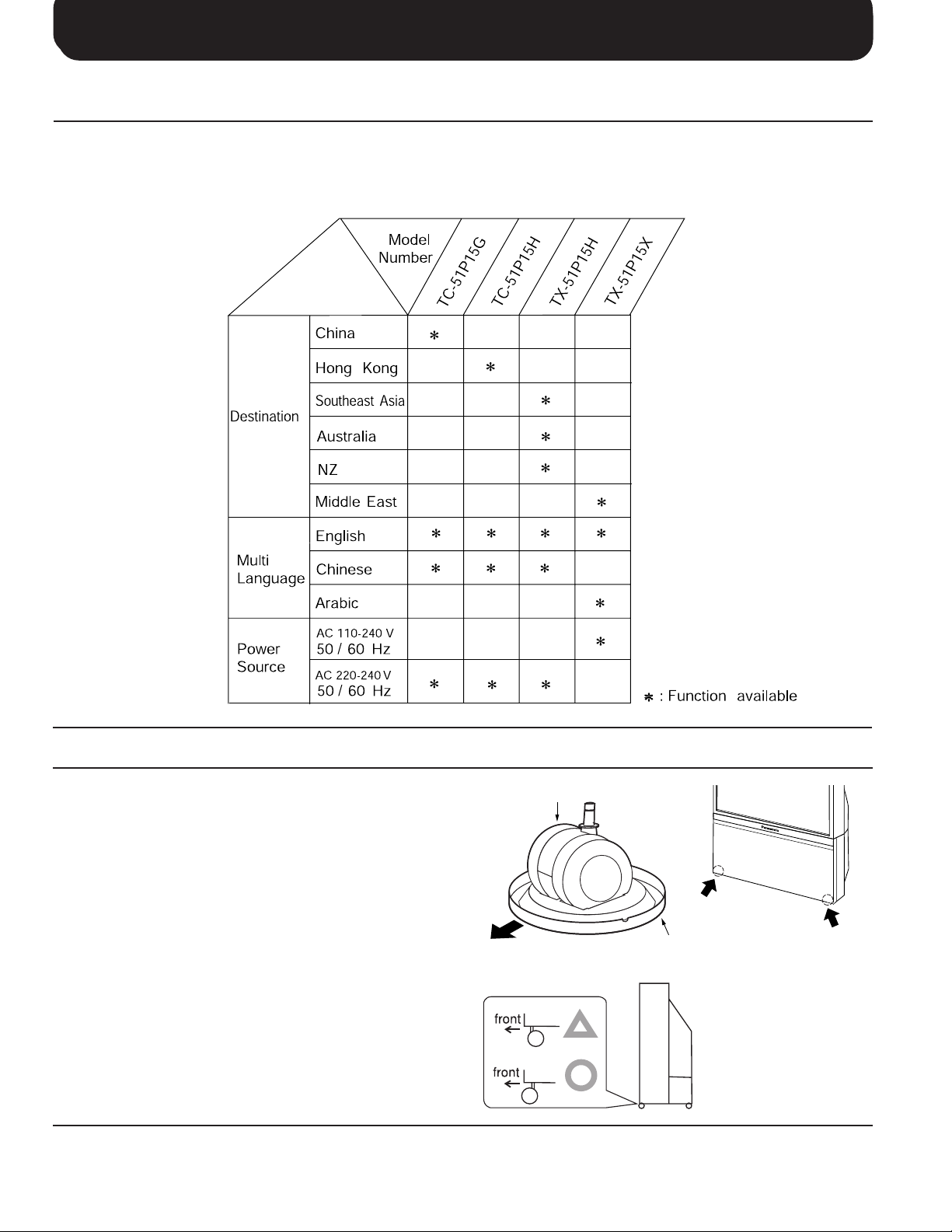
1. Check the Model Number of your TV set; the Model Number is shown on the rear cover name plate on the set.
Use the table on the opposite page to confirm which features your particular Model is equipped with. This will
help you to known which sections of the manual apply to your set.
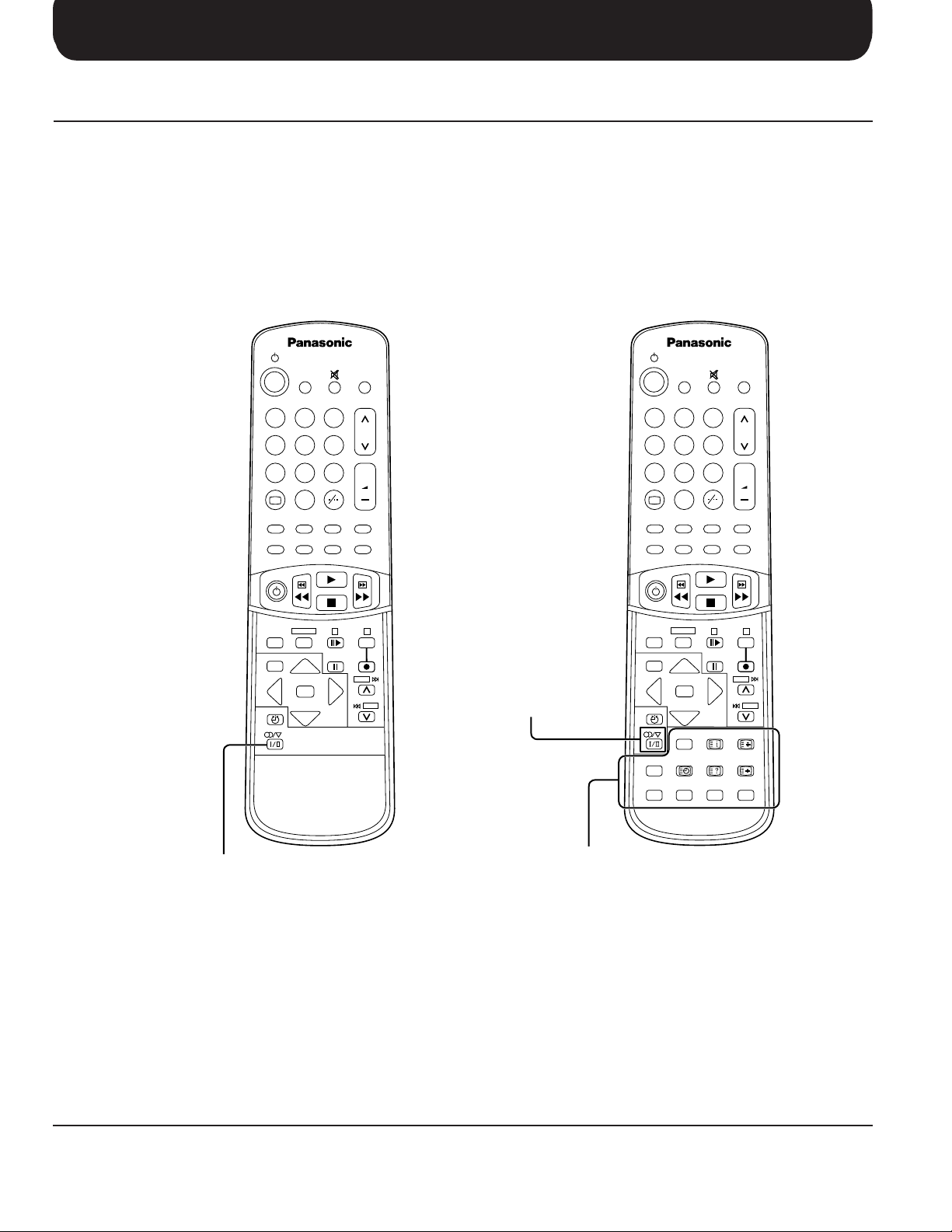
2. Check the Part Number on the rear of your Remote Control handpiece, and note the functions available, as
shown below.
TC-51P15G
TC-51P15H
SURROUND
TV/AV
213
546
8
79
+
0
D.PNR
CH SEARCH
STILL PIP
P. AI STROBE CHANGE PIP ACTION
VCR/LD/DVD
VCR
LD/DVD
DISC SIDE
A
MAIN MENU
RGB
REVEAL
SKIP
F/ T/ B
N
TV/TEXT INDEX HOLD
TIME
F.P.
TEXT
RGY B
TX-51P15H
TX-51P15X
SURROUND
213
546
8
+
B
Stereo / Bilingual
SKIP
Selection button
79
+
0
D.PNR
CH SEARCH
P. AI STROBE CHANGE PIP ACTION
VCR/LD/DVD
VCR
LD/DVD
MAIN MENU
N
TV/TEXT INDEX HOLD
TIME
F.P.
TEXT
TV/AV
STILL PIP
DISC SIDE
A
RGB
REVEAL
+
B
SKIP
SKIP
F/ T/ B
6
Stereo / Bilingual
Selection button
TELETEXT Operation
button
Before Operating This Set
Quick Reference Guide for your TV Set
Please check the model number of your set.
This Manual applies to several Models and there are slight differences among them.
Please check the table below to see what your TV is equipped with before you begin using these Operating Instructions.
Instructions are given for all functions, please disregard these which do not apply to your TV.
Securing the casters
To ensure safety, secure the casters in place using
the supplied stoppers.
This set is equipped with casters to enable it to be
easily moved. When positioning the set, place the
supplied stoppers under the casters to secure the
casters and prevent the set from moving.
To prevent the set from tipping forward, turn the two
casters on the front of the TV so they face forward,
as shown in the picture.
Front
caster
stopper
7
Before Operating This Set
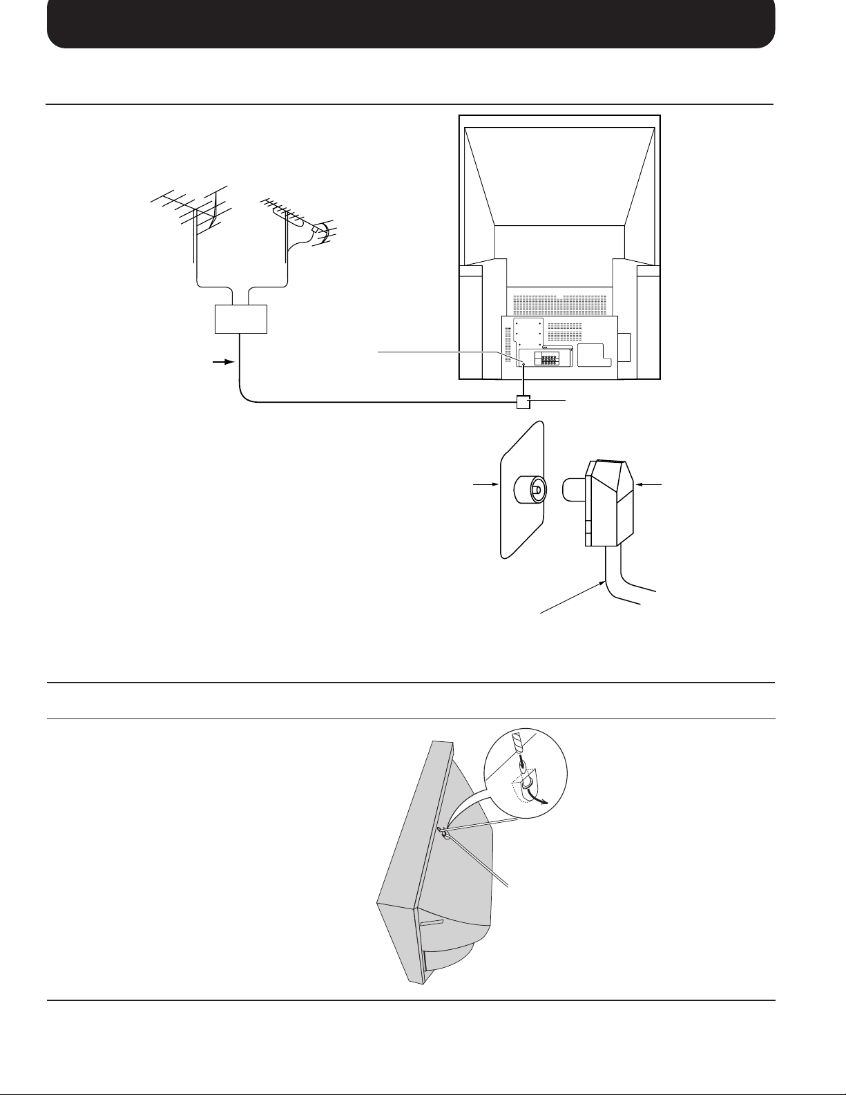
Connecting the Aerial Cable to the RF In Terminal
VHF Aerial
Mixer
75 Ohm
Coaxial Cable
To obtain optimum quality picture and sound, an
Aerial, the correct cable (75 Ohm coaxial) and the
correct terminating plug are required.
If a communal Aerial system is used, you may require
the correct connection cable and plug between the
wall Aerial socket and your set.
Your local Television Service Centre or Dealer may
be able to assist you in obtaining the correct Aerial
system for your particular area and accessories
required.
Any matters regarding Aerial installation, upgrading
of existing systems or accessories required, and the
costs incurred, are the responsibility of you, the
Customer.
UHF Aerial
RF In Terminal
RF In Terminal
Coaxial Aerial Plug
Coaxial aerial plug
75 Ohm Coaxial Cable
Safety Precaution
Please take safety precautions to prevent the unit
form falling over.
The unit may fall over during earthquakes, or if someone stands on or shakes the TV.
8
Fixing to a wall
Use a strong rope or a chain to
fasten the TV firmly to a strong
support such as a wall or a pillar.
Before Operating This Set
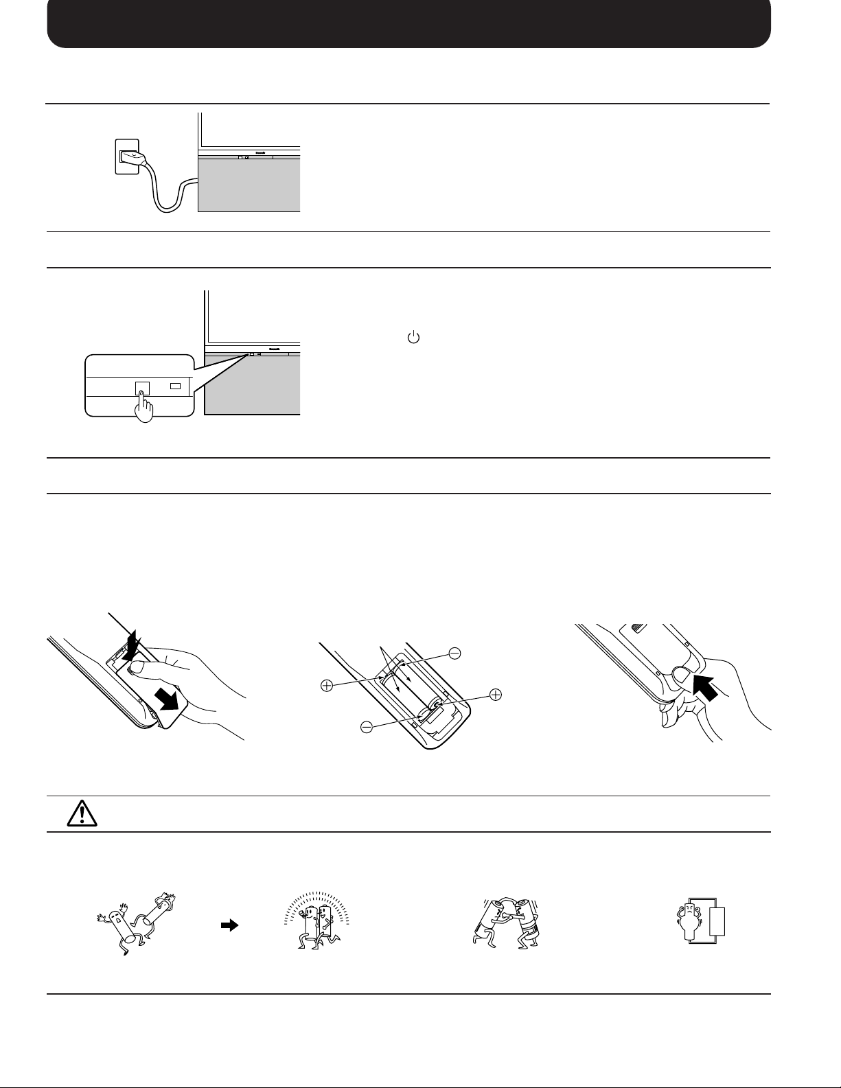
Connecting the Plug to the Wall Outlet
Note:
Main plug types vary between countries. The main plug shown at left
may therefore not be the type fitted to your set.
When connecting the main plug to the wall outlet, the power indicator
will light (Orange).
How to Turn the Power On
Push the Power switch on Television to turn the set on.
The Power Indicator will light.
Power-OFF
Stand-by
Power-ON
Note:
When in the Stand-by condition (Refer to page 32), it is possible to turn
the TV set on by pushing the “Power (Stand-by)” button any of the
“Direct Programme Number Selection” buttons (0~9) and Programme
Number Up and Down buttons on the TV set or Remote Control.
.......
......
.........
Orange
Red
Green
Battery Installation
1
Open the cover.
Apply slight downward
pressure while pulling
towards the bottom.
Do not use rechargeable (Ni-Cd) batteries.
They are different in shape and performance and may fail to ensure correct operation.
Battery cautions
The incorrect use of batteries can cause electrolyte leakage which will corrode the Remote Control or cause the
batteries to burst.
Old Batteries New Batteries
2
Batteries: Use two “R6 (AA)” size
batteries.
Insert the batteries ensuring correct polarity.
This is identifiable by the “+” and “−” symbols
on both the batteries and inside the battery
compartment.
Two “R6 (AA)” size
3
Replace the cover.
Replace both batteries at the same time. Don't mix battery types
(alkaline with carbon zinc, etc.)
Don't Recharge.
9
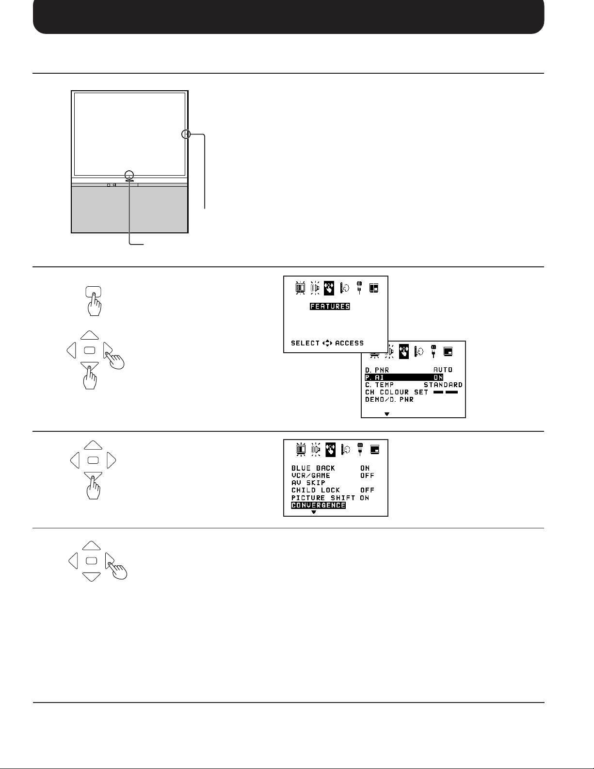
Convergence Adjustment
Convergence Adjustment mode
Prior to adjustment, tune the broadcast signal to the video input
signal and operate the set for more than 60 minutes. If the location or direction of the set is changed or moved, the display may
be out of alignment.
If necessary, carry out the following procedures once with PAL
signal and again with the NTSC signal.
Vertical centre marker
Horizontal centre marker
1
MAIN MENU
N
2
N
3
N
Push the “Main Menu” button.
Select the “FEATURES” menu
by using the Position Left “<”
or Right “>” button.
Push the Position Up “∧ ” or
Down “∨” button to enter
FEATURES function.
Select the “
menu by using the Position Up
“∧” or Down “∨” button.
Push the Position Left “<” or
Right “ > ” button to enter
CONVERGENCE ADJUSTMENT
mode.
CONVERGENCE
”
10
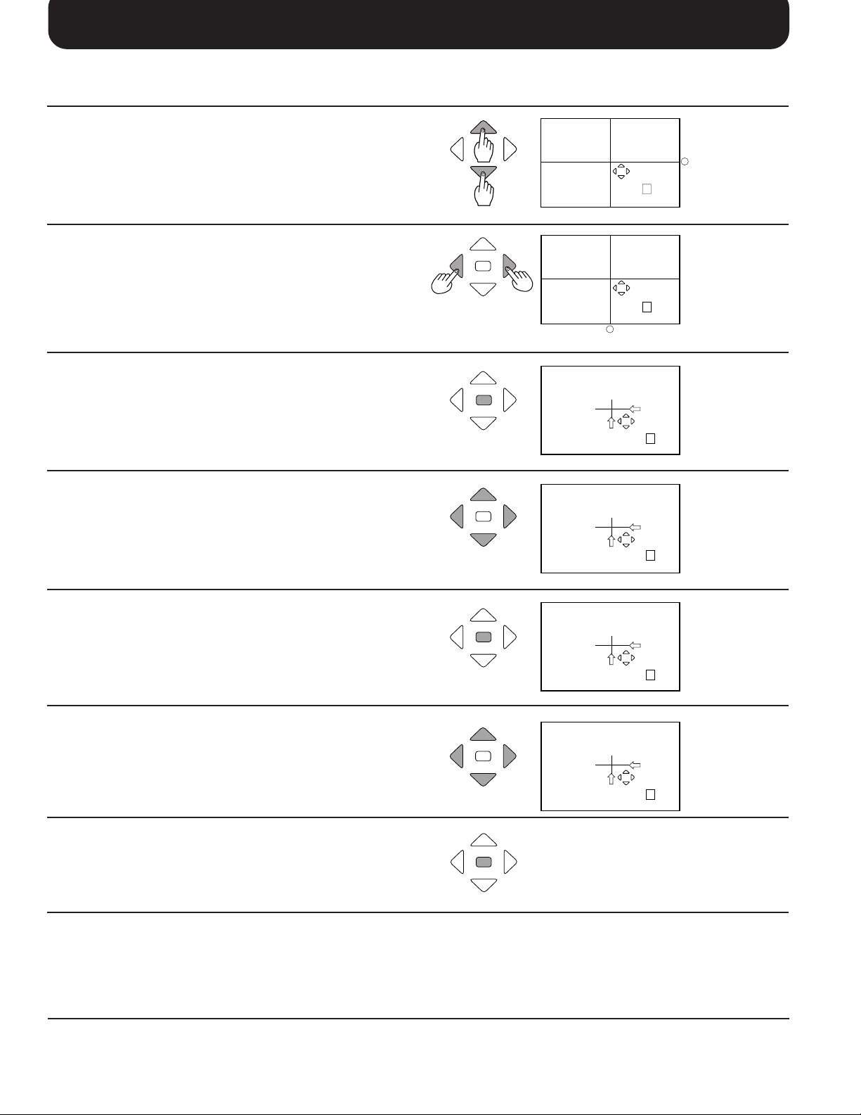
Convergence Adjustment
Convergence Adjustment for GREEN, RED and BLUE
Use the Position Up “∧” or Down “∨ ” button to
align the horizontal green line with the vertical
centre marker.
Use the Position Left “<” or Right “>” button to
align the vertical green line with the horizontal
centre marker.
Push the “N” button to adjust the red mode.
(Stores green)
NN
N
N
CONVERGENCE
NEXT: N
CONVERGENCE
NEXT: N
_
Horizontal centre marker
CONVERGENCE
NEXT: N
GREEN
GREEN
RED
_
Vertical center
marker
Use the Position Up “∧” or Down “∨”, Left “<” or
Right “>” buttons to align the red line with the
green line. (Becomes a yellow line)
Push the “N” button to adjust the blue mode.
(Stores red)
Use the Position Up “∧” or Down “∨” , Left “<” or
Right “>” buttons to align the blue line with the
yellow line. (Becomes a white line)
Push the “N” button to return to the normal
viewing. (Stores blue)
N
N
N
N
CONVERGENCE
RED
NEXT: N
CONVERGENCE
BLUE
NEXT: N
CONVERGENCE
BLUE
NEXT: N
If you wish to view a video with a different colour
system (PAL / SECAM, NTSC), repeat the steps
above while displaying a picture.
11

Location of Controls
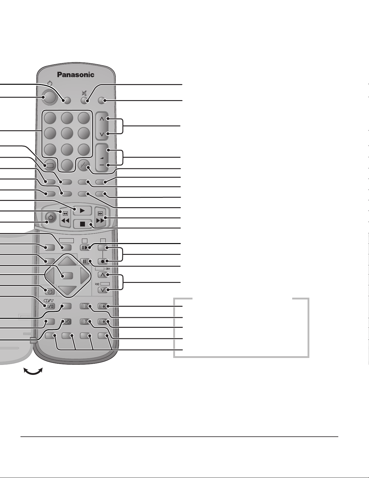
Remote Control
Surround (page 40)
Power (Stand-by) (page 32)
Direct Programme Number Selection (page 32)
Recall (page 33)
Channel Search (page 38)
D.PNR (page 39)
Strobe (page 38)
P.AI (page 39)
VCR / LD / DVD Play (page 55)
VCR / LD / DVD Rewind / Review (page 55)
VCR / LD / DVD Power (page 55)
LD / DVD button (page 54)
VCR button (page 54)
Main Menu (page 18)
Normalization (page 42, 43)
Position button
Off Timer button (page 33)
Stereo / Bilingual Sound Selection (page 41)
TC-51P15 Series are not equipped
TV / TEXT Selection (page 51)
TEXT Favourite Page Selection (page 51)
Time TEXT (page 52)
12
SURROUND
TV/AV
213
546
8
79
+
0
D.PNR
P.AI
CH SEARCH
STILL
STROBE
CHANGE
VCR/LD/DVD
+
PIP
PIP ACTION
Sound Mute (page 33)
TV / AV Mode Selection (page 33)
Programme Number Up and Down (page 32)
Volume Up and Down (page 32)
Two Digit Programme Number Selection (page
32)
Picture in Picture Selection (page 36)
Still (page 38)
PIP Action (page 37)
Main / Sub Picture Change (page 37)
OPEN
VCR
LD/DVD
MAIN MENU
N
TV/TEXT INDEX HOLD
TIME
TEXT
REVEALF.P.
DISC SIDE
A
SKIP
F/ T/ B
B
SKIP
VCR / LD / DVD Fast Forward / Cue (page 55)
VCR / LD / DVD Stop (page 55)
VCR Still Advance (VCR) (page 55)
DISC SIDE A Selection (LD / DVD)
VCR Record (VCR) (page 55)
VCR / LD / DVD Pause / Still (page 55)
Programme Number Up and Down
(VCR) (page 55)
TC-51P15 Series are not equipped
TEXT Hold (page 51)
TEXT Index (page 51)
TEXT Full / Top / Bottom Selection (page 51)
TEXT Reveal (page 51)
TEXT Colour-coded Button (page 51)
13
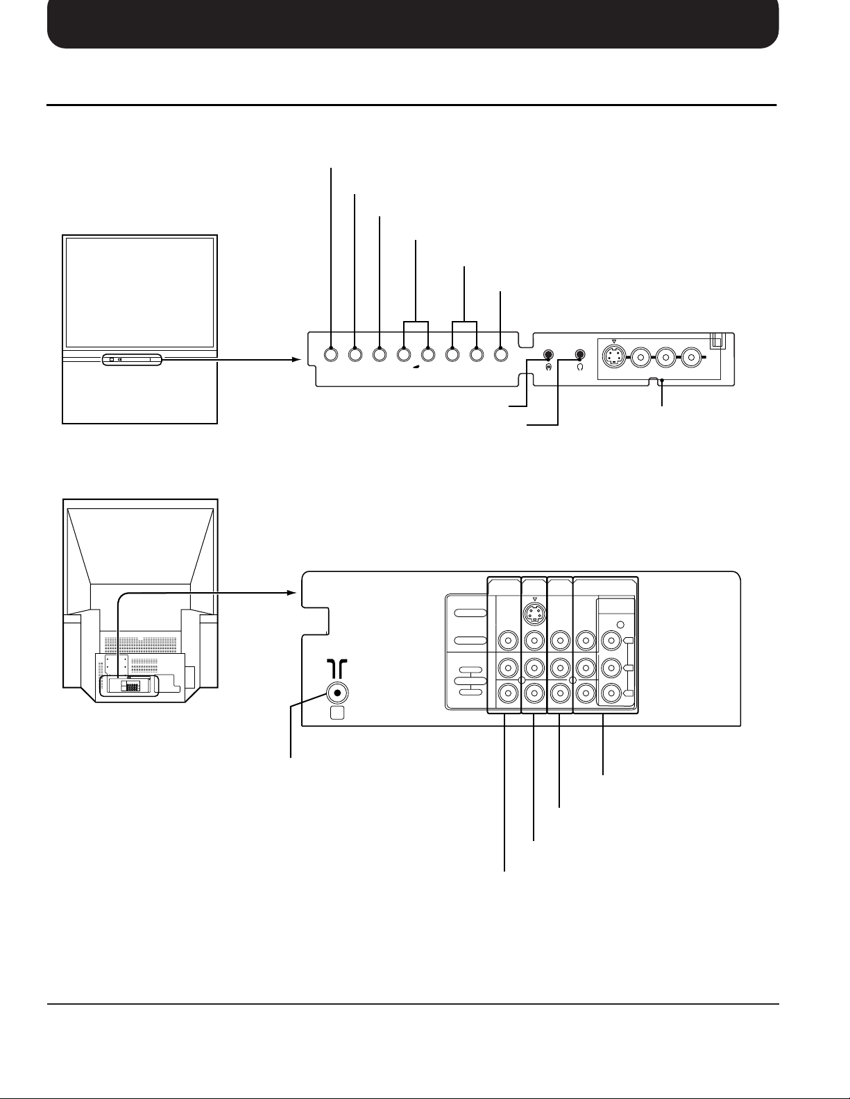
Location of Controls
Controls and Terminals on the TV
Display button (See page 33)
TV / AV Selection button (See page 33)
Preset button (See page 21)
Volume Up(+) / Down(
Programme Number button (See page 32)
TV/AV PRE.
DISPLAY GAME
-
^
+
^
Main headphone Jack (See page 17)
Sub headphone Jack (See page 17)
MONITOR
S - VIDEO
-
) button (See page 32)
Game button (See page 33)
Main Sub.
S-VIDEO VIDEO
AV2 Input Terminals
OUT
AV3
AV1
IN
IN
AV4
IN
DVD(Y•PB•PR)
AUDIO
AV2
IN
RL/MONO
14
Aerial Terminal (RF In Terminal)
(See page 8)
VIDEO
AUDIO
RIGHT
MONOMONO MONO
LEFT
Y
P
B
P
R
AV4 Input Terminals (See page 16)
AV3 Input Terminals (See page 15)
AV1 Input Terminals (See page 15)
Monitor Output Terminals (See page 16)
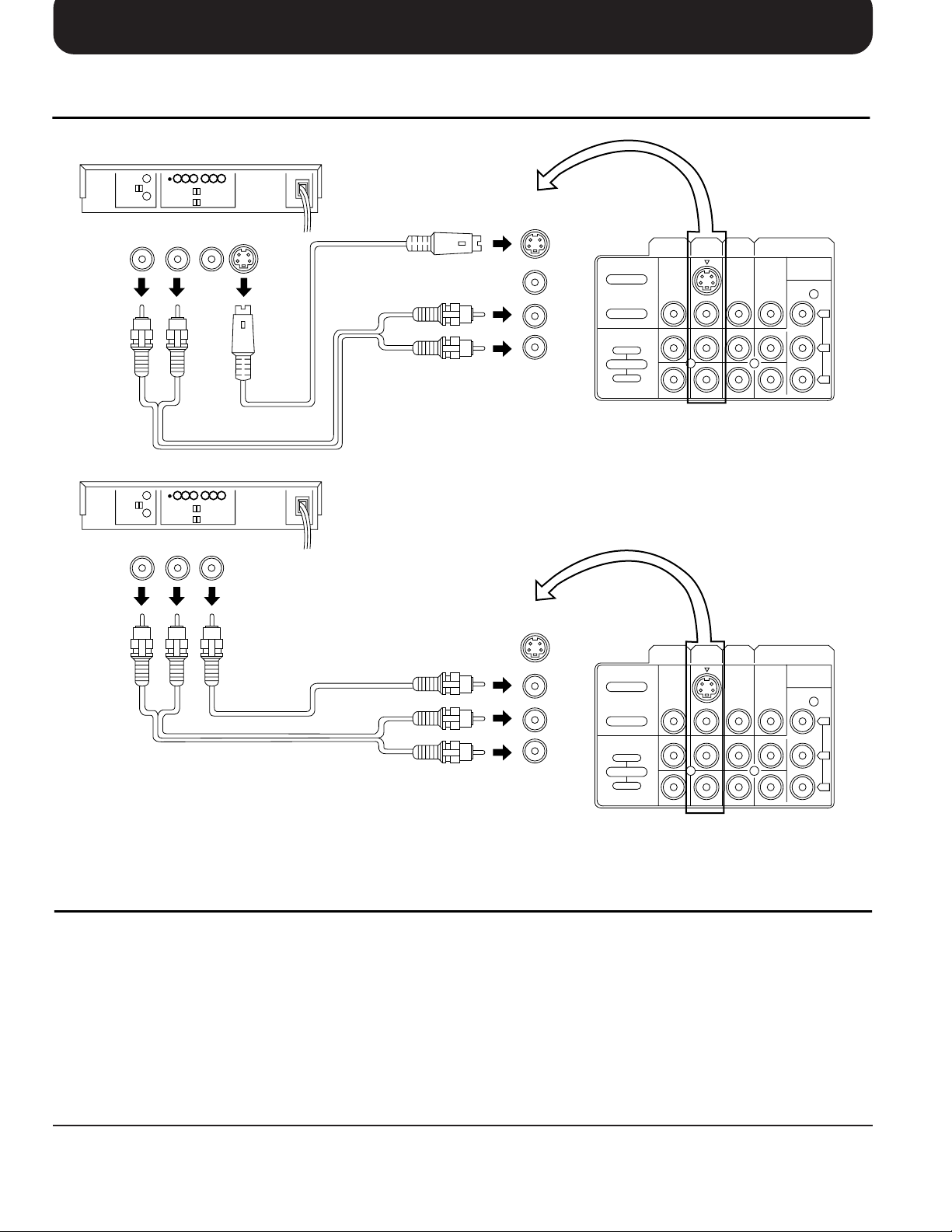
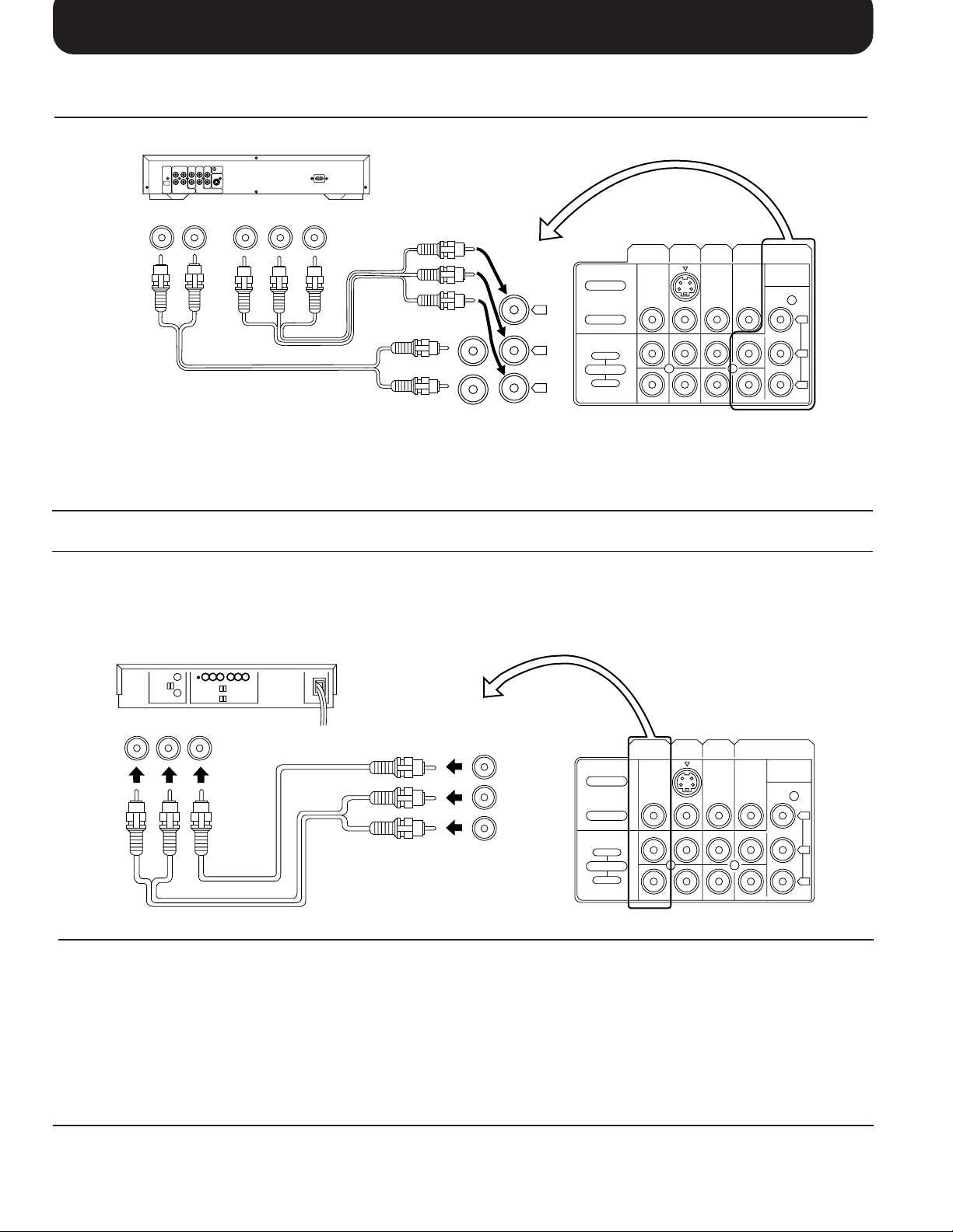
Connections
How to connect the “AV1, 2, 3 or 4” Input Terminals
(Super-VHS VCR)
AV1
MONO
IN
S Video
( )
input
S - VIDEO
VIDEO
LEFT
AUDIO
RIGHT
MONITOR
OUT
AV1
AV3
IN
IN
AV4
IN
DVD(Y•PB•PR)
MONOMONO MONO
Audio
OUT
RL
Video
(VHS VCR)
OUT
S-Video
OUT
VIDEO
AUDIO
Y
P
B
R
P
Audio
OUT
RL
Video
OUT
VIDEO
AUDIO
MONO
AV1
IN
S - VIDEO
VIDEO
LEFT
AUDIO
RIGHT
MONITOR
OUT
AV1
AV3
IN
IN
AV4
IN
DVD(Y•PB•PR)
Y
MONOMONO MONO
P
B
P
R
Note:
(1) When AV1, AV2, AV3 or AV4 is selected, and that AV mode has no input picture signal, the Background Colour of
the TV screen will change. (This only occurs if the Blue-Back function is set to the ON condition; refer to page 45
for details.)
(2) When an S-Video cable is connected to the S-Video terminal, the Video input will be automatically switched off for
that AV mode.
(3) When a Monaural VCR is used, connect the Monaural Audio cable to the Audio “L” (Left) terminal.
(4) Similar connections are available at the AV1, AV2, AV3 and AV4 input terminals.
Select the desired AV input position by pushing the TV/AV button. (Refer to page 33)
(5) The AV4 audio input terminals serves as the audio input terminal for both the Video input and for the DVD input.
15
Connections
How to connect the DVD Input Terminals
DVD Player
Audio
OUT
LR
DVD(Y•PB•PR) OUT
R
P
PBY
AUDIO
DVD(Y•PB•PR)
MONITOR
OUT
S - VIDEO
Y
P
B
P
R
VIDEO
LEFT
AUDIO
RIGHT
AV1
AV3
IN
IN
AV4
IN
DVD(Y•PB•PR)
Y
MONOMONO MONO
P
B
P
R
Note:
(1) The AV4 audio signal is common for both AV4 and DVD input signal terminals.
(2) The DVD signal input terminal takes priority over the AV4 video signal input terminal.
How to connect the AV Monitor Output Terminals to other equipment.
The “Monitor Out” Terminals output the same signals as main picture on the TV screen and sound from the speaker at
that time, e.g. TV programmes or signals from AV1, AV2, AV3 or AV4 input.
Recording Equipment
(VHS VCR)
Audio Video
RLIN IN
VIDEO
AUDIO
MONITOR
OUT
S - VIDEO
VIDEO
LEFT
AUDIO
RIGHT
MONITOR
OUT
AV1
AV3
IN
IN
AV4
IN
DVD(Y•PB•PR)
Y
MONOMONO MONO
P
B
R
P
Note:
(1) Never connect the same video recorder with both the VIDEO IN and MONITOR OUT terminals on this TV set, as
this could cause incorrect operation.
(2) The monitor output emits the main picture normal video and audio signals.
(3) Teletext display on screen will not be output at the MONITOR OUT terminals.
(4) Even if the television is in picture-in-picture condition, MONITOR OUT terminals output the same signals as main
picture on the screen and sound from speakers. Sub picture including strobe, still, channel search, etc. will not be
output at the MONITOR OUT terminals.
(5) DVD signal (Y, PB, PR) are not output at the MONITOR out terminals.
16
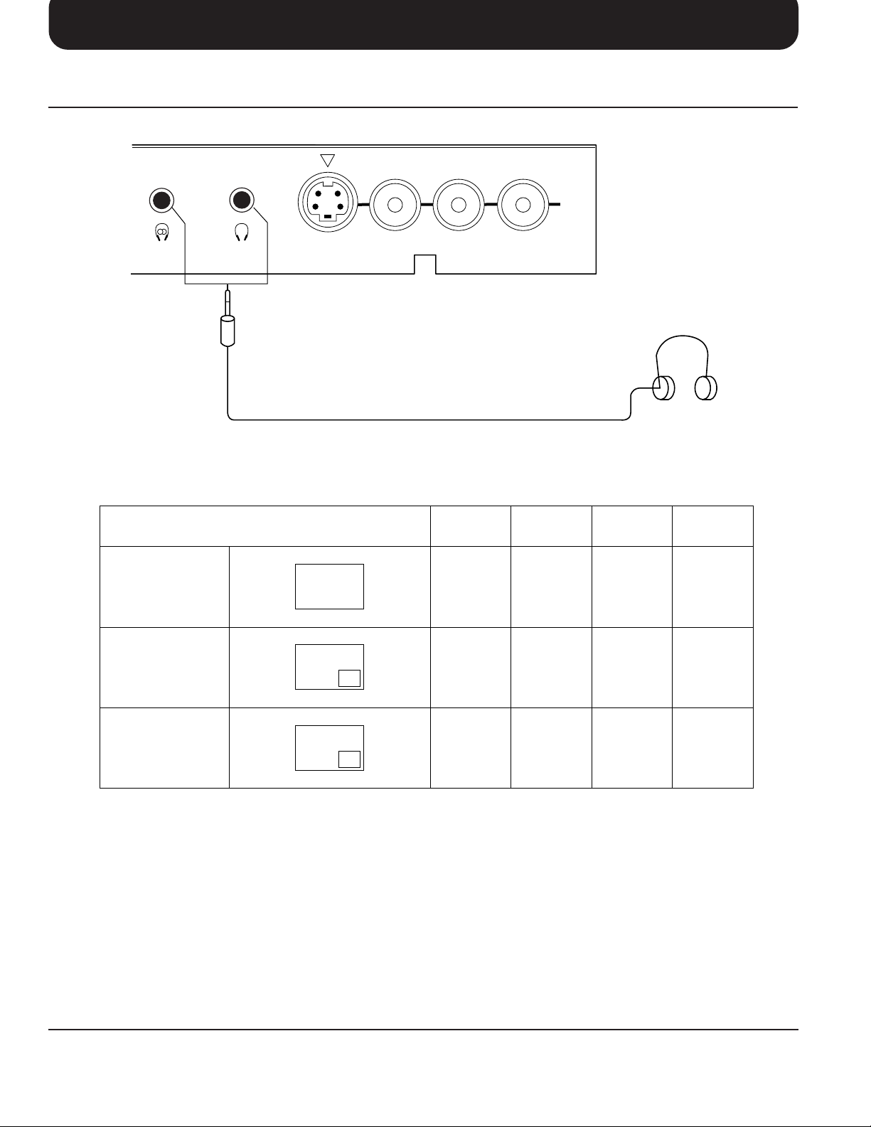
Connections
Connecting Headphones
Connect headphones as follows.
AV2
IN
Main Sub.
(3.5mm Plug)
You can listen to sound from each of the headphones plugs as shown below.
Screen condition
Single picture/
Teletext
S-VIDEO VIDEO
A
AUDIO
Speaker
Sound
A
(Stereo)
RL/MONO
Main
Headphones
(Stereo)
(Optional)
(not supplied)
Sub
Headphones
A
A
(Mono)
Monitor
Output
A
(Stereo)
Picture in Picture
Picture in Picture/
CHANGE
Main Headphones plug:
When a Main Headphones plug is inserted into the Headphones socket, all speakers will be automatically disconnected;
only the Main Headphones will function.
Use Volume Up “+” or Down “−” button to control volume level.
Sub Headphones plug:
For the sub Headphones volume control, refer to page 37.
A
B
B
A
A
(Stereo)
B
(Stereo)
A
(Stereo)
B
(Stereo)
B
(Mono)
A
(Mono)
A
(Stereo)
B
(Stereo)
17
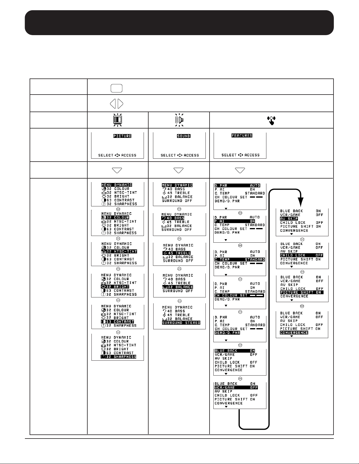
Flow Chart of Main menu
When the “MAIN MENU” button is pushed at the Main menu screen, the screen display will return to the normal
viewing condition.
When the “MAIN MENU” button is pushed at each menu screen (Picture, Sound, Features, Language, Preset, Multi
PIP), the screen display will return to the Main menu screen.
MAIN MENU
Push
Select
Symbol . Mark
On-Screen
Indication
Push
On-Screen
Indication
(example)
18
 Loading...