

Page 1
English
Français
Español
Model No.
TH-50LFC70U
TH-65LFC70U
TH-80LFC70U
Operating Instructions
FULL HD Display (for business use)
For more detailed instructions, refer to the Operating
Instructions on the CD-ROM.
Contents
Important Safety Instructions .....................2
•
FCC STATEMENT .....................................3
•
Important Safety Notice .............................4
•
Safety Precautions .....................................5
•
Accessories ................................................8
•
Connections .............................................10
•
Power On / Off .........................................14
•
Basic Controls ..........................................16
•
Speci cations ...........................................19
•
Panasonic Professional Flat Panel
•
Display Limited Warranty ........................21
LIMITED WARRANTY STATEMENT .......22
•
Customer Service ....................................23
•
• Please read these instructions before operating your set and
retain them for future reference.
• Illustrations and screens in this Operating Instructions are
images for illustration purposes, and may be different from
the actual ones.
• Descriptive illustrations in this Operating Instructions are
created mainly based on the 50 inch model.
TQB0AA0054
Page 2
CAUTION
RISK OF ELECTRIC SHOCK
DO NOT OPEN
WARNING: To reduce the risk of electric shock, do not remove cover or back.
No user-serviceable parts inside. Refer servicing to quali ed service personnel.
The lightning flash with
arrow-head within a triangle
is in tend ed to tell the user
that parts inside the product
are a risk of electric shock
to per sons.
The exclamation point within
a triangle is intended to
tell the user that important
operating and servicing
instructions are in the papers
with the ap pli ance.
WARNING : To prevent damage which may result in re or shock hazard, do not expose this apparatus to
Do not place containers with water ( ower vase, cups, cosmetics, etc.) above the set.
(including on shelves above, etc.)
WARNING : 1) To prevent electric shock, do not remove cover. No user serviceable parts inside. Refer servicing
2) Do not remove the grounding pin on the power plug. This apparatus is equipped with a three pin
Do not defeat the purpose of the grounding plug.
rain or mois ture.
to quali ed service personnel.
grounding-type power plug. This plug will only t a grounding-type power outlet. This is a safety
fea ture. If you are unable to insert the plug into the outlet, contact an electrician.
Important Safety Instructions
1) Read these instructions.
2) Keep these instructions.
3) Heed all warnings.
4) Follow all instructions.
5) Do not use this apparatus near water.
6) Clean only with dry cloth.
7) Do not block any ventilation openings. Install in accordance with the manufacturer’s instructions.
8) Do not install near any heat sources such as radiators, heat registers, stoves, or other apparatus (including
ampli ers) that produce heat.
9) Do not defeat the safety purpose of the polarized or grounding-type plug. A polarized plug has two blades with
one wider than the other. A grounding type plug has two blades and a third grounding prong. The wide blade
or the third prong are provided for your safety. If the provided plug does not t into your outlet, consult an
electrician for replacement of the obsolete outlet.
10) Protect the power cord from being walked on or pinched particularly at plugs, convenience receptacles, and
the point where they exit from the apparatus.
11) Only use attachments / accessories speci ed by the manufacturer.
12) Use only with the cart, stand, tripod, bracket, or table speci ed by the manufacturer, or sold
with the apparatus. When a cart is used, use caution when moving the cart / apparatus
combination to avoid injury from tip-over.
13) Unplug this apparatus during lightning storms or when unused for long periods of time.
14) Refer all servicing to quali ed service personnel. Servicing is required when the apparatus has been damaged
in any way, such as power-supply cord or plug is damaged, liquid has been spilled or objects have fallen into
the apparatus, the apparatus has been exposed to rain or moisture, does not operate normally, or has been
dropped.
15) To prevent electric shock, ensure the grounding pin on the AC cord power plug is securely connected.
2
Page 3
FCC STATEMENT
This equipment has been tested and found to comply with the limits for a Class B digital device, pursuant to Part
15 of the FCC Rules. These limits are designed to provide reasonable protection against harmful interference
in a residential installation. This equipment generates, uses and can radiate radio frequency energy and, if not
installed and used in accordance with the instructions, may cause harmful interference to radio communications.
However, there is no guarantee that interference will not occur in a particular installation. If this equipment does
cause harmful interference to radio or television reception, which can be determined by turning the equipment
off and on, the user is encouraged to try to correct the interference by one or more of the following measures:
• Reorient or relocate the receiving antenna.
• Increase the separation between the equipment and receiver.
• Connect the equipment into an outlet on a circuit different from that to which the receiver is connected.
• Consult the dealer or an experienced technician for help.
This device complies with Part15 of the FCC Rules. Operation is subject to the following two conditions: (1) This
device may not cause harmful interference, and (2) this device must accept any interference received, including
interference that may cause undesired operation.
FCC CAUTION:
To assure continued compliance, follow the attached installation instructions and use only shielded
interface cables when connecting to computer or peripheral devices. Some recommended user provided
interface cables may require usage of the attached ferrite core kit(s), refer to interface cable connection
instructions for details. Any changes or modi cations not expressly approved by Panasonic Corp. of
North America could void the user’s authority to operate this device.
FCC Declaration of Conformity
Model No. TH-50LFC70U, TH-65LFC70U, TH-80LFC70U
Responsible Party: Panasonic Corporation of North America
Two Riverfront Plaza, Newark, New Jersey 07102-5490
Contact Source: Panasonic System Communications Company of North America
1-877-655-2357
CANADIAN NOTICE:
This Class B digital apparatus complies with Canadian ICES-003.
Note:
Image retention may occur. If you display a still picture for an extended period, the image might remain on the
screen. However, it will disappear after a while.
Trademark Credits
• VGA is a trademark of International Business Machines Corporation.
• Microsoft
• Macintosh, Mac, Mac OS, OS X and Safari are the trademarks of Apple Inc. registered in the United States and
• SVGA, XGA, SXGA and UXGA are registered trademarks of the Video Electronics Standard Association.
• HDMI, the HDMI Logo, and High-De nition Multimedia Interface are trademarks or registered trademarks of
• RoomView, Crestron RoomView and Fusion RV are registered trademarks of Crestron Electronics, Inc, and
• Miracast is a trademark of Wi-Fi Alliance.
• Android is a registered trademark of Google Inc.
• iPad, iPhone, and iPod touch are trademarks of Apple Inc., registered in the U.S. and other countries.
®
Microsoft Corporation in the United States and/or other countries.
other countries.
Even if no special notation has been made of company or product trademarks, these trademarks have been
fully respected.
HDMI Licensing LLC in the United States and other countries.
Crestron Connected is the trademark of Crestron Electronics, Inc.
, Windows®, Windows Vista®, and Internet Explorer® are the registered trademarks or trademarks of
3
Page 4

Important Safety Notice
WARNING
1) To prevent damage which may result in re or shock hazard, do not expose this appliance to dripping
or splashing.
Do not place containers with water ( ower vase, cups, cosmetics, etc.) above the set. (including on
shelves above, etc.)
No naked ame sources, such as lighted candles, should be placed on / above the set.
2) To prevent electric shock, do not remove cover. No user serviceable parts inside. Refer servicing to quali ed
service personnel.
3) Do not remove the earthing pin on the power plug. This apparatus is equipped with a three pin earthing-type
power plug. This plug will only t an earthing-type power outlet. This is a safety feature. If you are unable to
insert the plug into the outlet, contact an electrician.
Do not defeat the purpose of the earthing plug.
4) To prevent electric shock, ensure the earthing pin on the AC cord power plug is securely connected.
CAUTION
This appliance is intended for use in environments which are relatively free of electromagnetic elds.
Using this appliance near sources of strong electromagnetic elds or where electrical noise may overlap with the
input signals could cause the picture and sound to wobble or cause interference such as noise to appear.
To avoid the possibility of harm to this appliance, keep it away from sources of strong electromagnetic elds.
4
Page 5

Safety Precautions
WARNING
Setup
This LCD Display is for use only with the following optional accessories. Use with any other type of optional
accessories may cause instability which could result in the possibility of injury.
• Pedestal .................................................................................... TY-ST42P50 (for 50 inch model)*,
• Mobile stand for Display ............................................................ TY-ST50PB2 (for 50 inch model),
• Mobile stand ..............................................................................TY-ST58PF20 (for 50 inch model)
• Wall-hanging bracket (vertical) .................................................. TY-WK42PV20 (for 50 inch model),
• Wall-hanging bracket (angled) .................................................. TY-WK42PR20 (for 50 inch model),
• Ceiling-hanging bracket ............................................................ TY-CE42PS20 (for 50 inch model)
• BNC Dual Video Terminal Board ............................................... TY-FB9BD
• HD-SDI Terminal Board ............................................................. TY-FB9HD
• HD-SDI Terminal Board with audio ........................................... TY-FB10HD
• Dual Link HD-SDI Terminal Board ............................................. TY-FB11DHD
• Dual HDMI Terminal Board ....................................................... TY-FB10HMD
• DVI-D Terminal Board ............................................................... TY-FB11DD
• Digital Interface Box .................................................................. ET-YFB100G
*Precaution for use of TY-ST42P50 (for 50 inch model)
Use a stand pole “for plasma display (long)” (part number: TBLA3679, TBLA3680).
We are not responsible for any product damage, etc. caused by use of the pedestal, wall-hanging bracket or
ceiling-hanging bracket made by other companies, or by failures in the installation environment for the pedestal,
wall-hanging bracket or ceiling-hanging bracket even during the warranty period.
Always be sure to ask a quali ed technician to carry out set-up.
Small parts can present choking hazard if accidentally swallowed. Keep small parts away from young children. Discard
unneeded small parts and other objects, including packaging materials and plastic bags/sheets to prevent them from
being played with by young children, creating the potential risk of suffocation.
Do not place the Display on sloped or unstable surfaces, and ensure that the Display does not hang over the
edge of the base.
• The Display may fall off or tip over.
Do not place any objects on top of the Display.
• If water is spills onto the Display or foreign objects get inside it, a short-circuit may occur which could result in re
or electric shock. If any foreign objects get inside the Display, please consult your local Panasonic dealer.
Transport only in upright position!
•
Transporting the unit with its display panel facing upright or downward may cause damage to the internal circuitry.
Ventilation should not be impeded by covering the ventilation openings with items such as newspapers, table
cloths and curtains.
For suf cient ventilation;
If using the pedestal (optional accessory), leave a space of 3
(7 cm) or more at the rear, and also keep the space between the bottom of the display and the oor surface.
If using some other setting-up method, follow the manual of it. (If there is no speci c indication of installation
dimension in the installation manual, leave a space of 3
3/4
and 2
” (7 cm) or more at the rear.)
Cautions for Wall or ceiling Installation
• Wall or ceiling installation should be performed by an installation professional. Installing the Display incorrectly may
lead to an accident that results in death or serious injury. Use the speci ed accessories.
•
If you terminate the use of the Display on the wall or ceiling, ask a professional to remove the Display as soon as possible.
• When mounting the Display on the wall, prevent the mounting screws and power cable from contacting metal objects
inside the wall. An electric shock may occur if they contact metal objects inside the wall.
Do not install the product to a place where the product is exposed to direct sunlight.
• If the screen is exposed to direct sunlight, the liquid crystal panel may have adverse effect.
(All of the following accessories are manufactured by Panasonic Corporation.)
TY-ST65P20 (for 65 inch model and 80 inch model)
TY-ST65PB2 (for 65 inch model),
TY-ST80LF70 (for 80 inch model)
TY-WK70PV50 (for 80 inch model)
TY-WK65PR20 (for 65 inch model)
15/16
” (10 cm) or more at the top, left and right, and 2
15/16
” (10 cm) or more at the top, bottom, left and right,
3/4
”
5
Page 6

Safety Precautions
When using the LCD Display
The Display is designed to operate on 110 - 127 V AC, 50/60 Hz.
Do not cover the ventilation holes.
• Doing so may cause the Display to overheat, which can cause re or damage to the Display.
Do not stick any foreign objects into the Display.
• Do not insert any metal or ammable objects into the ventilations holes or drop them onto the Display, as doing so
can cause re or electric shock.
Do not remove the cover or modify it in any way.
• High voltages which can cause severe electric shocks are present inside the Display. For any inspection, adjustment
and repair work, please contact your local Panasonic dealer.
Ensure that the mains plug is easily accessible.
An apparatus with CLASS I construction shall be connected to a mains socket outlet with a protective earthing
connection.
Do not use any power supply cord other than that provided with this unit.
• Doing so may cause re or electric shocks.
Securely insert the power supply plug as far as it will go.
• If the plug is not fully inserted, heat may be generated which could cause re. If the plug is damaged or the wall
socket is loose, they shall not be used.
Do not handle the power supply plug with wet hands.
• Doing so may cause electric shocks.
Do not do anything that may damage the power cable. When disconnecting the power cable, pull on the plug
body, not the cable.
• Do not damage the cable, make any modi cations to it, place heavy objects on top of it, heat it, place it near any
hot objects, twist it, bend it excessively or pull it. To do so may cause re and electric shock. If the power cable is
damaged, have it repaired at your local Panasonic dealer.
Do not remove covers and NEVER modify the Display yourself
• Do not remove the rear cover as live parts are accessible when it is removed. There are no user serviceable parts
inside. (High-voltage components may cause serious electrical shock.)
• Have the Display checked, adjusted, or repaired at your local Panasonic dealer.
If the Display is not going to be used for any prolonged length of time, unplug the power supply plug from
the wall outlet.
To prevent the spread of re, keep candles or other open ames away from this product at all times.
If problems occur during use
If a problem occurs (such as no picture or no sound), or if smoke or an abnormal odour starts to come out
from the Display, immediately unplug the power supply plug from the wall outlet.
• If you continue to use the Display in this condition, re or electric shock could result. After checking that the smoke
has stopped, contact your local Panasonic dealer so that the necessary repairs can be made. Repairing the Display
yourself is extremely dangerous, and shall never be done.
If water or foreign objects get inside the Display, if the Display is dropped, or if the cabinet becomes damages,
disconnect the power supply plug immediately.
• A short circuit may occur, which could cause re. Contact your local Panasonic dealer for any repairs that need to
be made.
6
Page 7

Safety Precautions
CAUTION
When using the LCD Display
Do not bring your hands, face or objects close to the ventilation holes of the Display.
• Heated air comes out from the ventilation holes at the top of Display will be hot. Do not bring your hands or face,
or objects which cannot withstand heat, close to this port, otherwise burns or deformation could result.
Be sure to disconnect all cables before moving the Display.
• If the Display is moved while some of the cables are still connected, the cables may become damaged, and re or
electric shock could result.
Disconnect the power supply plug from the wall socket as a safety precaution before carrying out any
cleaning.
• Electric shocks can result if this is not done.
Clean the power cable regularly to prevent it becoming dusty.
• If dust built up on the power cord plug, the resultant humidity can damage the insulation, which could result in re.
Pull the power cord plug out from the wall outlet and wipe the mains lead with a dry cloth.
Do not burn or breakup batteries.
• Batteries must not be exposed to excessive heat such as sunshine, re or the like.
Cleaning and maintenance
The front of the display panel has been specially treated. Wipe the panel surface gently using only a cleaning
cloth or a soft, lint-free cloth.
• If the surface is particularly dirty, wipe with a soft, lint-free cloth which has been soaked in pure water or water in
which neutral detergent has been diluted 100 times, and then wipe it evenly with a dry cloth of the same type until
the surface is dry.
• Do not scratch or hit the surface of the panel with ngernails or other hard objects, otherwise the surface may
become damaged. Furthermore, avoid contact with volatile substances such as insect sprays, solvents and thinner,
otherwise the quality of the surface may be adversely affected.
If the cabinet becomes dirty, wipe it with a soft, dry cloth.
• If the cabinet is particularly dirty, soak the cloth in water to which a small amount of neutral detergent has been
added and then wring the cloth dry. Use this cloth to wipe the cabinet, and then wipe it dry with a dry cloth.
• Do not allow any detergent to come into direct contact with the surface of the Display. If water droplets get inside
the unit, operating problems may result.
• Avoid contact with volatile substances such as insect sprays, solvents and thinner, otherwise the quality of the
cabinet surface may be adversely affected or the coating may peel off. Furthermore, do not leave it for long periods
in contact with articles made from rubber or PVC.
Usage of a chemical cloth
• Do not use a chemical cloth for the panel surface.
• Follow the instructions for the chemical cloth to use it for the cabinet.
Wired LAN
When setting up the Display at a place, where electric statistic occurs often, take a suf cient anti-static
measure before start using.
•
When the Display is used at a location, where static electricity occurs often, such as on a carpet, communications
of the DIGITAL LINK and the wired LAN are disconnected more often. In that case, remove static electricity and the
noise source that may cause problems with an antistatic mat, and re-connect the DIGITAL LINK and the wired LAN.
•
In rare cases, the LAN connection is disabled due to static electricity or noise. In that case, turn off the power of the
Display and the connected devices once and then re-turn on the power. Connect the DIGITAL LINK and the LAN.
The Display may not work properly due to strong radiowave from the broadcast station or the radio.
• If there is any facility or equipment, which outputs strong radiowave, near the installation location, set up the
Display at a location suf ciently far from the source of the radiowave. Or, wrap the LAN cable connected to the
DIGITAL LINK terminal by using a piece of metal foil or a metal pipe, of which is grounded at both ends.
7
Page 8
Accessories
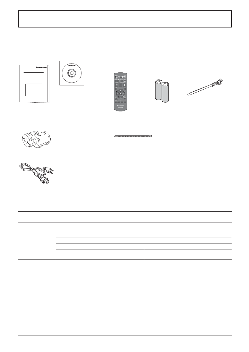
Accessories Supply
Check that you have the accessories and items shown
Operating
Instruction book
Software CD-ROM × 1
Remote Control
Transmitter
N2QAYB000691
Batteries for the Remote
Control Transmitter
(R6 (UM3) Size × 2)
Clamper × 1
TMME289
Ferrite core × 2
J0KG00000014
Use the Ferrite cores
to comply with the EMC
standard. (see page 9)
Power supply cord
Attention
Store small parts in an appropriate manner, and keep them away from young children.
Cable tie × 2
TMM17499
Contents in the CD-ROM
The contents below are included in the supplied CD-ROM.
Instruction
(PDF)
Software
Operating Instructions - Display Operations
Operating Instructions - Network Operations
Operating Instructions - Wireless Manager ME
Software license GNU GENERAL PUBLIC LICENSE
GNU LESSER GENERAL PUBLIC LICENSE
Wireless Manager ME (Windows/Mac) Allows the image on the computer screen to be
sent wirelessly or via wired LAN.
Switch the input to Panasonic APPLICATION
before use. For more details, see the instruction
manual of Wireless Manager ME.
8
Page 9

Accessories
Remote Control Batteries
Requires two R6 batteries.
1. Pull and hold the hook, then open
the battery cover.
2. Insert batteries - note correct
polarity (+ and -).
“R6 (UM3)” size
-
+
+
-
Helpful Hint:
For frequent remote control users, replace old batteries with Alkaline
batteries for longer life.
Precaution on battery use
Incorrect installation can cause battery leakage and corrosion that will damage the remote control transmitter.
Disposal of batteries should be in an environment-friendly manner.
Observe the following precaution:
1. Batteries shall always be replaced as a pair. Always use new batteries when replacing the old set.
2. Do not combine a used battery with a new one.
3. Do not mix battery types (example: “Zinc Carbon” with “Alkaline”).
4. Do not attempt to charge, short-circuit, disassemble, heat or burn used batteries.
5.
Battery replacement is necessary when remote control acts sporadically or stops operating the Display set.
6. Do not burn or breakup batteries.
7. Batteries must not be exposed to excessive heat such as sunshine, re or the like.
3. Replace the cover.
How to use the Ferrite core
PC with DVI-D
video out
Stereo mini plug (M3)
Less than
1.97 inch (5 cm)
DVI-video cable (Within 5 m)
Installing the Ferrite core
1.
Pull back the tabs
(in two places)
Ferrite core
(supplied)
2.
Open the
Ferrite core
Less than
1.97 inch (5 cm)
3.
Route the
cable through
and close
Shared with PC IN.
4.
Fix the Ferrite
core with the
cable tie
9
Page 10

Connections
AC cord connection and xing, cable xing
For 50 inch and 65 inch models
When using the Wall-hanging bracket (vertical) (for 50 inch model)
Note:
When using the Wall-hanging bracket (vertical) (TY-WK42PV20), use the holes
clamper is used on the hole
50 inch model
, the cables may be caught by the wall-hanging bracket.
AC cord xing
Plug the AC cord into the display unit.
Plug the AC cord until it clicks.
Note:
Make sure that the AC cord is locked on
both the left and right sides.
65 inch model
Unplug the AC cord
Unplug the AC cord pressing the
two knobs.
Note:
When disconnecting the AC cord, be
absolutely sure to disconnect the AC
cord plug at the socket outlet rst.
and to secure the cables. If the
Using the clamper
Secure any excess cables with clamper as required.
Note:
One clamper is supplied with this unit. In case of securing cables at three positions, please purchase it separately.
If you need more clampers, purchase them from your dealer. (Available from the customer service)
Attach the clamper
1
Insert the clamper
in a hole.
hole
To remove from the unit:
snaps
Keep pushing
both side snaps
Bundle the cables
2
hooks
Set the
tip in the
hooks
To loosen:
knob
10
Keep
pushing
the knob
Page 11

Connections
For 80 inch model
AC cord xing
Unplug the AC cord
Unplug the AC cord pressing the
Plug the AC cord into the display unit.
Plug the AC cord until it clicks.
Note:
Make sure that the AC cord is locked on
both the left and right sides.
Using the clamper
Secure any excess cables with clamper as required.
Note:
One clamper is supplied with this unit. In case of securing cables at four positions, please purchase it separately.
If you need more clampers, purchase them from your dealer. (Available from the customer service)
two knobs.
Note:
When disconnecting the AC cord, be
absolutely sure to disconnect the AC
cord plug at the socket outlet rst.
Attach the clamper
1
Insert the clamper
in a hole.
hole
To remove from the unit:
snaps
Keep pushing
both side snaps
Bundle the cables
2
hooks
Set the
tip in the
hooks
To loosen:
knob
Keep
pushing
the knob
11
Page 12

Connections
Speaker connection
Please use 8 /10 W speaker.
Video equipment connection
For 50 inch and 65 inch models
SLOT: Terminal board (optional accessories) insert slot (see page 5)
Note:
The right side slot is for terminal board with 2-slot
width. The terminal board with 1-slot width does
not function when installed in the right side slot.
AV IN (VIDEO): Composite Video
Input Terminal
COMPONENT/RGB IN: Component/
RGB Video
Input Terminal
AUDIO 1 IN:
Audio input terminal
shared with VIDEO
and COMPONENT/
RGB IN.
PC OUT:
Monitor Out Terminal.
Video signals being reproduced
on the display are output to
another sub monitor as PC video
signals.
Red
Black
1
While pressing the lever,
insert the core wire.
SERIAL:
Serial Control
Terminal.
Control the Display
by connecting to PC.
Red
Black
2
Return the lever.
AUDIO 2 IN:
Audio input
terminal shared
with DVI-D IN and
PC IN.
PC IN: PC Input Terminal
Connect to video terminal of PC or equipment
with Y, P
B(CB
DVI-D IN: DVI-D Input Terminal
*
DIGITAL LINK is technology that enables signals such as audio and video to be transmitted using twisted pair cables.
For details, see the Operating Instructions - “Network Operations”.
) and PR(CR) output.
AV IN (HDMI 1, HDMI 2):
HDMI Input Terminal
Connect to video equipment
such as VCR or DVD player.
LAN, DIGITAL LINK*
Connect to a DIGITAL LINK input terminal network to control
the Display. Alternatively, connect to a device that sends
video and audio signals via the DIGITAL LINK terminal.
12
Page 13

For 80 inch model
AV IN (VIDEO): Composite Video Input Terminal
COMPONENT/RGB IN: Component/RGB Video
AUDIO 1 IN:
Audio input terminal
shared with VIDEO
and COMPONENT/
RGB IN.
Input Terminal
AV IN (HDMI 1, HDMI 2): HDMI Input
Terminal
Connect to video equipment such as
VCR or DVD player.
Connections
SLOT: Terminal board (optional accessories) insert slot
(see page 5)
Note:
The upper side slot is for terminal board with 2-slot width. The
terminal board with 1-slot width does not function when installed in
the upper side slot.
PC OUT:
SERIAL:
Serial Control Terminal.
Control the Display
by connecting to
PC.
Monitor Out Terminal.
Video signals being
reproduced on the display
are output to another sub
monitor as PC video signals.
AUDIO 2 IN:
Audio input terminal
shared with DVI-D IN
and PC IN.
PC IN: PC Input Terminal
Connect to video terminal of PC or
equipment with Y, P
output.
DVI-D IN: DVI-D Input Terminal
*
DIGITAL LINK is technology that enables signals such as audio and video to be transmitted using twisted pair cables.
For details, see the Operating Instructions - “Network Operations”.
B(CB) and PR(CR)
LAN, DIGITAL LINK*
Connect to a DIGITAL LINK input terminal network
to control the Display. Alternatively, connect to a
device that sends video and audio signals via the
DIGITAL LINK terminal.
13
Page 14

Power On / Off
Connecting the AC cord plug to the Display.
Connecting the plug to the Wall Outlet
Notes:
• Main plug types vary between countries. The power
plug shown at right may, therefore, not be the type
tted to your set.
• When disconnecting the AC cord, be absolutely sure
to disconnect the AC cord plug at the socket outlet
rst.
Press the Power switch on the Display to turn the set
on: Power-On.
Power switch
Power Indicator: Green
[Starting up the network]
It takes some time for the network to start up just
after the power is turned on.
During that time, “Network Setup” in the “Setup”
menu is grayed out and cannot be set.
Press the button on the remote control to turn the Display off.
Power Indicator: Red (standby)
Press the
Power Indicator: Green
Turn the power to the Display off by pressing the
the Display is on or in standby mode.
Note:
During operation of the power management function, the power indicator turns
orange in the power off state.
button on the remote control to turn the Display on.
14
Power Indicator
switch on the unit, when
Remote Control Sensor
Page 15

Power On / Off
When rst switching on the unit
Following screen will be displayed when the unit is turned on for the rst time.
Select the items with the remote control. Unit buttons are invalid.
OSD Language
OSD Language
English (UK)
Deutsch
Français
Italiano
Español
ENGLISH (US)
Notes:
• Once the items are set, the screens won't be displayed when switching on the unit next time.
• After the setting, the items can be changed in the following menus.
OSD Language
1
Select the
language.
2
Set.
Day/Time Settings
Power ON message
The following message may be displayed when turning the unit power ON:
Day/Time Settings
Day/Time Settings
Set
Day MON
Time
Day/Time Settings
Set
Day TUE
Time MON 99:99
18:00
Time TUE 99:99
18:00Time
1
Select “Day”
or “Time”.
2
Setup “Day”
or “Time”.
1
Select “Set”.
2
Set.
No activity power off Precautions
’No activity power off’ is enabled.
If “No activity power off” in Setup menu is set to “Enable”, a warning message is displayed every time the
power is turned ON.
Power Management Information
Last turn off due to 'Power management'.
If “Power management” is functioned, an information message is displayed every time the power is turned ON.
These message displays can be set with the following menu: Options menu
Power On Message (No activity power off)
Power On Message (Power Management)
Displaying network information
The network information for the Display will be displayed in the following scenarios.
The power is turned ON with Panasonic APPLICATION selected as the input.
The input is switched to Panasonic APPLICATION.
button is pushed with Panasonic APPLICATION selected as the input.
The
Display example:
Panasonic APPLICATION
S-DIRECT Name1234 Proj1234
Display ID
Display name
Wireless LAN network number
15
Page 16

INPUT
MENU
VOL
ENTER/
+
/
-
/
Basic Controls
Main Unit
For 50 inch and 65 inch models
Remote control
sensor
Power Indicator
The Power Indicator will light.
• Power-OFF .... Indicator not illuminated (The unit will still
• Standby ........ Red
• Power-ON ...... Green
• HDMI1 Power management
HDMI2 Power management
......................... Orange (With HDMI1 or HDMI2 input signal.)
• PC Power management (DPMS)
......................... Orange (With PC input signal.)
• DVI-D Power management
......................... Orange (With DVI input signal.)
Note:
If the power indicator is orange, power consumption during standby
is generally larger than that of when the power indicator is red.
Brightness Sensor
Detects the brightness in the viewing environment.
USB (VIEWER):
consume some power as long as the power
cord is still inserted into the wall outlet.)
Orange (When “Slot power” is set to “On”
and Terminal Board is installed.)
Orange (Depending on the type of the
function board installed, when the power is
supplied to the slot)
Orange (When “Control I/F Select” is set to
“DIGITAL LINK/LAN” or “Wireless Network
Standby” is set to “On”. Refer to “Operating
Instructions, Network Operations”)
Connect to USB memory.
16
SLOT: Terminal board (optional accessories) insert
slot (see page 5)
Note:
The right side slot is for terminal board with 2-slot
width. The terminal board with 1-slot width does not
function when installed in the right side slot.
Enter / Aspect button
Volume Adjustment
Volume Up “+” Down “–”
When the menu screen is displayed:
“+” : press to move the cursor up
“–” : press to move the cursor down
MENU Screen ON / OFF
Each time the MENU button is pressed, the menu screen will switch.
INPUT button (INPUT signal selection)
Main Power On / Off Switch
Page 17

For 80 inch model
Remote control
sensor
Basic Controls
Power Indicator
The Power Indicator will light.
• Power-OFF .... Indicator not illuminated (The unit will still
• Standby ........ Red
• Power-ON ...... Green
• HDMI1 Power management
HDMI2 Power management
......................... Orange (With HDMI1 or HDMI2 input signal.)
• PC Power management (DPMS)
......................... Orange (With PC input signal.)
• DVI-D Power management
......................... Orange (With DVI input signal.)
Note:
If the power indicator is orange, power consumption during standby
is generally larger than that of when the power indicator is red.
Brightness Sensor
Detects the brightness in the viewing environment.
consume some power as long as the power
cord is still inserted into the wall outlet.)
Orange (When “Slot power” is set to “On”
and Terminal Board is installed.)
Orange (Depending on the type of the
function board installed, when the power is
supplied to the slot)
Orange (When “Control I/F Select” is set to
“DIGITAL LINK/LAN” or “Wireless Network
Standby” is set to “On”. Refer to “Operating
Instructions, Network Operations”)
USB (VIEWER): Connect to USB memory.
ENTER/
+
VOL
-
MENU
INPUT
SLOT: Terminal board (optional accessories) insert
slot (see page 5)
Note:
The upper side slot is for terminal board with 2-slot
width. The terminal board with 1-slot width does not
function when installed in the upper side slot.
Enter / Aspect button
Volume Adjustment
Volume Up “+” Down “–”
/
/
When the menu screen is displayed:
“+” : press to move the cursor up
“–” : press to move the cursor down
MENU Screen ON / OFF
Each time the MENU button is pressed, the menu screen will switch.
INPUT button (INPUT signal selection)
Main Power On / Off Switch
17
Page 18

Basic Controls
Remote Control Transmitter
ACTION button
Press to make selections.
ASPECT button
Press to adjust the aspect.
Standby (ON / OFF) button
The Display must rst be plugged into
the wall outlet and turned on at the
power switch (see page 14).
Press this button to turn the Display
On, from Standby mode. Press
it again to turn the Display Off to
Standby mode.
POS./SIZE button
PICTURE button
Sound mute On / Off
Press this button to mute the
sound.
Press again to reactivate sound.
Sound is also reactivated when
power is turned off or volume level
is changed.
N button
POSITION buttons
INPUT button
Press to select Input signal
sequentially.
ECO MODE (ECO)
Press to change the ECO MODE
setup status.
FUNCTION buttons (FUNCTION)
OFF TIMER button
The Display can be preset to switch to stand-by
after a xed period. The setting changes to 30
minutes, 60 minutes, 90 minutes and 0 minutes
(off timer cancelled) each time the button is
pressed.
30 min 60 min
90 min
0 min (Cancel)
When three minutes remain, “Off timer 3 min”
will ash.
The off timer is cancelled if a power interruption
occurs.
AUTO SETUP button
Automatically adjusts the position/
size of the screen.
SET UP button
SOUND button
Volume Adjustment
Press the Volume Up “+” or Down
“–” button to increase or decrease
the sound volume level.
R button
Press the R button to return to
previous menu screen.
RECALL button
Press the “RECALL” button to display
the current system status.
Input label
1
Aspect mode
2
Audio input
Pro le name
Off timer
3
The off timer indicator is
displayed only when the off
timer has been set.
Clock display
4
PC
4:3
COMPONENT
Memory name: MEMORY2
1
2
18
10:00
4
Digital Zoom
Off timer
90min
3
Page 19

Speci cations
Power Source 110 - 127 V AC, 50/60 Hz
Power Consumption
LCD Display panel 50-inch VA panel (LED backlight),
Screen size 43.1” (W) × 24.2” (H) × 49.5” (diagonal) /
Operating condition
Applicable signals
Connection terminals
Sound
Dimensions (W × H × D) 45.4” × 26.5” × 3.7” /
Mass (weight) approx. 66.2 lbs / 30.0 kg net approx. 121.3 lbs / 55.0 kg net
Power on 135 W 210 W
Stand-by condition 0.5 W
Power off condition 0.3 W
1,095 mm (W) × 616 mm (H) × 1,257 mm
(No.of pixels) 2,073,600 (1,920 (W) ×1,080 (H))
Temperature 32 °F - 104 °F (0 °C - 40 °C)
Humidity 20 % - 80 % (no condensation)
Colour System NTSC, PAL, PAL60, SECAM, Modi ed NTSC
Scanning format 525 (480) / 60i · 60p, 625 (575) / 50i · 50p, 750 (720) / 60p · 50p, 1125 (1080) / 60i · 60p · 50i ·
PC signals VGA, SVGA, XGA, SXGA
AV IN VIDEO
COMPONENT/RGB IN
DVI-D IN
PC IN
DIGITAL LINK / LAN For RJ45 network and DIGITAL LINK connections, compatible with PJLink™
AUDIO 1 IN
HDMI 1
HDMI 2
P
P
AUDIO 1 IN
AUDIO 2 IN
AUDIO 2 IN
SERIAL External Control Terminal
PC OUT R: 0.7 Vp-p (75 )
USB (VIEWER) TYPE A USB connector
EXT SP 8 , 20 W [10 W + 10 W] (10 % THD)
Speakers 120 mm × 40 mm × 2 pcs
Audio Output 20 W [10 W + 10 W] (10 % THD)
50p · 24p · 25p · 30p · 24psF, 1250 (1080) / 50i
BNC
Stereo mini jack (M3) × 1
TYPE A Connector × 2
Y/G
BNC
BNC
B/CB/B
BNC
R/CR/R
Stereo mini jack (M3) × 1
DVI-D 24 Pin
Content Protection
Stereo mini jack (M3) × 1
High-Density Mini D-sub 15 Pin
Stereo mini jack (M3) × 1
D-sub 9 Pin RS-232C compatible
G: 0.7 Vp-p (75 )
B: 0.7 Vp-p (75 )
HD/VD: 1.0 - 5.0 Vp-p
Communication method: RJ45 100BASE-TX
TH-50LFC70U TH-65LFC70U
16:9 aspect ratio
(diagonal)
UXGA ···· (compressed)
Horizontal scanning frequency 15 - 110 kHz
Vertical scanning frequency 48 - 120 Hz
1,151 mm × 672 mm × 94 mm
[5,760 × 1,080 dots]
65-inch VA panel (LED backlight),
56.2” (W) × 31.6” (H) × 64.5” (diagonal) /
1,428 mm (W) × 803 mm (H) × 1,638 mm
1.0 Vp-p (75 )
0.5 Vrms, Shared with COMPONENT/RGB IN
with sync 1.0 Vp-p (75 )
0.7 Vp-p (75 )
0.7 Vp-p (75 )
0.5 Vrms, Shared with VIDEO
Compliance with DVI Revision 1.0
Compatible with HDCP 1.1
0.5 Vrms, Shared with PC IN
Y or G with sync 1.0 Vp-p (75 )
Y or G without sync 0.7 Vp-p (75 )
P
B/CB/B: 0.7 Vp-p (75 )
P
R/CR/R: 0.7 Vp-p (75 )
HD/VD: 1.0 - 5.0 Vp-p (high impedance)
0.5 Vrms, Shared with DVI-D IN
1,484 mm × 859 mm × 97 mm
16:9 aspect ratio
(diagonal)
58.5” × 33.8” × 3.9” /
19
Page 20

Speci cations
Power Source 110 - 127 V AC, 50/60 Hz
Power Consumption
LCD Display panel 80-inch VA panel (LED backlight), 16:9 aspect ratio
Screen size 69.7” (W) × 39.2” (H) × 80.0” (diagonal) /
Operating condition
Applicable signals
Connection terminals
Sound
Dimensions (W × H × D) 73.6” × 43.1” × 3.9” / 1,868 mm × 1,093 mm × 99 mm
Mass (weight) approx. 183.0 lbs / 83.0 kg net
Power on 345 W
Stand-by condition 0.5 W
Power off condition 0.3 W
(No.of pixels) 2,073,600 (1,920 (W) ×1,080 (H))
Temperature 32 °F - 104 °F (0 °C - 40 °C)
Humidity 20 % - 80 % (no condensation)
Colour System NTSC, PAL, PAL60, SECAM, Modi ed NTSC
Scanning format 525 (480) / 60i · 60p, 625 (575) / 50i · 50p, 750 (720) / 60p · 50p, 1125 (1080) / 60i · 60p · 50i ·
PC signals VGA, SVGA, XGA, SXGA
AV IN VIDEO
COMPONENT/RGB IN
DVI-D IN
PC IN
DIGITAL LINK / LAN For RJ45 network and DIGITAL LINK connections, compatible with PJLink™
AUDIO 1 IN
HDMI 1
HDMI 2
P
P
AUDIO 1 IN
AUDIO 2 IN
AUDIO 2 IN
SERIAL External Control Terminal
PC OUT R: 0.7 Vp-p (75 )
USB (VIEWER) TYPE A USB connector
EXT SP 8 , 20 W [10 W + 10 W] (10 % THD)
Speakers 120 mm × 40 mm × 2 pcs
Audio Output 20 W [10 W + 10 W] (10 % THD)
50p · 24p · 25p · 30p · 24psF, 1250 (1080) / 50i
BNC
Stereo mini jack (M3) × 1
TYPE A Connector × 2
Y/G
BNC
BNC
B/CB/B
BNC
R/CR/R
Stereo mini jack (M3) × 1
DVI-D 24 Pin
Content Protection
Stereo mini jack (M3) × 1
High-Density Mini D-sub 15 Pin
Stereo mini jack (M3) × 1
D-sub 9 Pin RS-232C compatible
G: 0.7 Vp-p (75 )
B: 0.7 Vp-p (75 )
HD/VD: 1.0 - 5.0 Vp-p
Communication method: RJ45 100BASE-TX
1,771 mm (W) × 996 mm (H) × 2,032 mm (diagonal)
Horizontal scanning frequency 15 - 110 kHz
Vertical scanning frequency 48 - 120 Hz
TH-80LFC70U
[5,760 × 1,080 dots]
UXGA ···· (compressed)
1.0 Vp-p (75 )
0.5 Vrms, Shared with COMPONENT/RGB IN
with sync 1.0 Vp-p (75 )
0.7 Vp-p (75 )
0.7 Vp-p (75 )
0.5 Vrms, Shared with VIDEO
Compliance with DVI Revision 1.0
Compatible with HDCP 1.1
0.5 Vrms, Shared with PC IN
Y or G with sync 1.0 Vp-p (75 )
Y or G without sync 0.7 Vp-p (75 )
P
B/CB/B: 0.7 Vp-p (75 )
R/CR/R: 0.7 Vp-p (75 )
P
HD/VD: 1.0 - 5.0 Vp-p (high impedance)
0.5 Vrms, Shared with DVI-D IN
Note:
Design and speci cations are subject to change without notice. Mass and dimensions shown are approximate.
20
Page 21

(for the U.S.A and Puerto Rico)
Panasonic Solutions Company
Unit of Panasonic Corporation of
North America
Two Riverfront Plaza, Newark,
New Jersey 07102-5490
Panasonic Professional Flat Panel Display
Panasonic Solutions Company. (referred to as “the
Warrantor”) will repair this product and all included
accessories with new or refurbished parts, free of
charge in the USA or Puerto Rico, of the original
purchase in the event of a defect in materials or workmanship as follows:
Models or Parts
Professional Flat
Panel Display
On-site or carry-in service in the USA and Puerto Rico
may be obtained during the warranty period by contacting
Panasonic Solutions Company Service toll free at
1-877-655-2357.
This warranty is extended only to the original purchaser
and is non transferable. A purchase receipt or other
proof of date of original purchase will be required before
warranty service is rendered.
This warranty only covers failures due to defects in
materials or workmanship, which occur during normal
use. The warranty does not cover damage which occur
in shipment, or failures which are caused by products
not supplied by the warrantor, or failures which result
from improper installation, set-up adjustments, improper
Part
Warranty
2 Years 2 Years
Labor
Warranty
Limited Warranty
antenna, inadequate signal pickup, maladjustment of
consumer controls, improper operation, power line surge,
improper voltage supply, lighting damage, or service by
anyone other than an authorized repair facility, or
damage that is attributable to acts of God.
LIMITS AND EXCLUSIONS
There are no express warranties except as listed above.
THE WARRANTOR SHALL NOT BE LIABLE FOR
INCIDENTAL OR CONSEQUENTIAL DAMAGES
(INCLUDING, WITHOUT LIMITION, DAMAGE
TO DISCS) RESULTING FROM THE USE OF THIS
PRODUCT, OR ARISING OUT OF ANY BREACH OF
THE WARRANTY. ALL EXPRESS AND IMPLIED
WARRANTIES, INCLUDING THE WARRANTIES
OF MERCHANTABILITY AND FITNESS FOR
PARTICULAR PURPOSE, ARE LIMITED TO THE
APPLICABLE WARRANTY PERIOD SET FORTH
ABOVE.
Some states do not allow the exclusion or limitation
of incidental or consequential damages, or limitations
on how long an implied warranty lasts, so the above
exclusions or limitations may nor apply to you. This
warranty gives you specific legal rights and you may
other rights, which vary from state to state.
If you have a problem with this product that is not
handled to your satisfaction, then write the Consumer
Affairs Department at the Company address indicated
above.
In the USA and Puerto Rico
FOR SERVICE
CALL TOLL FREE
1-877-655-2357
21
Page 22

(for Canada)
THIS EXPRESS, LIMITED WARRANTY IS IN LIEU OF ALL OTHER
WARRANTIES, EXPRESS OR IMPLIED, INCLUDING ANY IMPLIED
WARRANTIES OF MERCHANTABILITY AND FITNESS FOR A PARTICULAR
PURPOSE. IN NO EVENT WILL PANASONIC CANADA INC. BE LIABLE FOR
ANY SPECIAL, INDIRECT OR CONSEQUENTIAL DAMAGES.
In certain instances, some jurisdictions do not allow the exclusion or limitation of
incidental or consequential damages, or the exclusion of implied warranties, so the
above limitations and exclusions may not be applicable.
this warranty.
Serial numbers that have been altered, defaced or removed void this warranty. This
warranty does not cover replacements or repairs necessitated by loss or damage
resulting from any cause beyond the control of PCI.
Marking or retained images (sometimes called “burn-in”) resulting from the display of
fixed images on video display products are not defects and are not covered under
safety windows, etc. This warranty does not apply to any part, or parts, of the
product, installed, altered, repaired or misused in any way that, in the opinion of PCI,
affects the reliability of or detracts from the performance of the product.
For products requiring routine preventive maintenance, that maintenance must be
performed in order to maintain warranty coverage.
Repaired or replacement parts supplied during the warranty coverage period carry
the unexpired portion of the original warranty coverage period. Proof of product
purchase is a condition of warranty service. The owner must produce the product
purchase receipt or other satisfactory evidence of date of original purchase.
This warranty does not apply to external appearance items, such as handles, knobs,
exchange, any part that becomes defective. However, the product must be
purchased and serviced in Canada. The product or part that shows evidence of
defect must be delivered prepaid or carried in to an authorized Panasonic Broadcast
Service Center. This warranty does not cover shipping costs.
The warranty coverage period is one year for both parts and labour beginning with
the date of original end user purchase, subject to the exceptions as stated below.
Panasonic Canada Inc. (also known as PCI) warrants this product to be free of
defects in material and workmanship under normal use during the applicable
warranty coverage period described below. PCI agrees to repair, or at its option,
LIMITED WARRANTY STATEMENT
5770 Ambler Drive, Mississauga, Ontario L4W 2T3
Panasonic Canada Inc.
22
or damage to the product while in transit.
dramatically decreases the interval between performances of routine preventive
maintenance required to maintain this warranty coverage.
• Dust, smoke, rental/staging environment and twenty-four/seven operation,
Warranty Service
If the product needs to be shipped for service, carefully pack (preferably in the
original carton) and enclose a letter, detailing the complaint. Send prepaid and
adequately insured to the local authorized Panasonic Service Centre in your
area or to Panasonic Technical Support and Product Services Department, 5770
Ambler Drive, Mississauga, Ontario, L4W 2T3. Shipping to the latter location
requires a return authorization before shipment. No liability is assumed for loss
103 inch Plasma displays
Hard Drive Disk Unit
3 years (burn-in not covered)
1 year plus balance (if any) of
the original Manufacturer’s
Limited Warranty.
(Content not covered)
3 years
1 year
* LCD Projectors below
Projector Lamps
All Plasma displays 2 years (burn-in not covered) 2 years
2,500 ANSI Lumens
2,500 ANSI Lumens
50% of the rated lamp life or 1 year.
Whichever comes first
Whichever comes first
3 years or 1,500 hrs.
Whichever comes first
Whichever comes first.
3 years or 1,500 hrs.
Whichever comes first
50% of the rated lamp life or 1 year.
Whichever comes first.
Imaging Block
All LCD Monitors
* DLP™ Projectors
* LCD Projectors above
2 years (burn-in not covered)
3 years or 17,000 hrs.
Whichever comes first
3 years or 2,500 hrs.
2 years
3 years or 17,000 hrs.
Whichever comes first
3 years or 2,500 hrs.
Video Heads
D5 Video heads
Maintenance Items
Colour Camera CCD
1 year or 2,000 hrs. (prorated)
Whichever comes first
1 year or
Whichever comes first
90 days
2 years
1,0
00 hrs.
1 year or 2,000 hrs.
Whichever comes first
1 year or 1,000 hrs.
Whichever comes first
90 days
2 years
WARRANTY COVERAGE PERIOD EXCEPTIONS
Item
Video Tape
P2/SD Cards
Parts
30 days— Replacement only
(content not covered)
(Content not covered)
Labour
N/A
N/A
Page 23

23
Page 24

USA only: Disposal may be regulated in your community due to
environmental considerations. For disposal or recycling information,
please visit Panasonic website: http://www.panasonic.com/environmental
or call 1-888-769-0149.
Customer’s Record
The model number and serial number of this product can be found on its rear panel. You should note this serial
number in the space provided below and retain this book, plus your purchase receipt, as a permanent record of your
purchase to aid in identi cation in the event of theft or loss, and for Warranty Service purposes.
Model Number Serial Number
Panasonic System Communications Company of North America
Unit of Panasonic Corporation of North America
Executive Of ce :
Two Riverfront Plaza, Newark, New Jersey 07102-5490
Panasonic Canada Inc.
5770 Ambler Drive
Mississauga, Ontario
L4W 2T3
Web Site : http://panasonic.net
¤
Panasonic Corporation 2014
Printed in China
 Loading...