

Page 1
TC-26LX60L
TC-32LX60L
LH58
MTNC060583CE
B05
LCD TV
CONTENTS
Page Page
1 Safety precautions 3
2 Warning
2.1. Prevention of Electro Static Discharge (ESD) to
Electrostatically Sensitive (ES) Devices
3 About lead free solder (PbF)
4 Receiver feature table
5 Chassis Board Layout
6 Location of controls (EUR7613Z90R or EUR7613ZE0)
7 Service Mode
7.1. How to enter into adjustment mode
7.2. Adjustment method.....Use the remote control.
7.3. Cancellation
7.4. Contents of adjustment mode
8 Troubleshooting Guide
8.1. Self-check function
8.2. How to access
8.3. Screen Display
9 Disassembly Instructions 8
3
3
4
5
6
7
8
8
8
8
8
8
8
8
8
9.1. Removing the LCD panel assembly and LCD L/R MTG
9.2. Removing the LCD panel and LCD T/B MTG
10 Measurements and Adjustments
10.1. White Balance Adjustment
11 MTS circuit adjustment
12 Boards Assemblies
12.1. AP-Board
12.2. A-Board
12.3. P-Board
12.4. G-Board
12.5. V-Board
13 Block Diagram
13.1. Block Diagram for P and AP (DC-DC CONV.) (1 of 2)
13.2. Block Diagram for P and AP (DC-DC CONV.) (2 of 2)
14 Schematic Diagrams
14.1. Schematic Diagram Notes
© 2006 Panasonic Corporation of North America. All
rights reserved. Unauthorized copying and
distribution is a violation of law.
11
11
12
12
13
14
14
15
16
17
18
19
19
20
21
21
Page 2

14.2. Reference of PDF links color 22
14.3. A-Board (1 of 7) Schematic Diagram
14.4. A-Board (2 of 7) Schematic Diagram
14.5. A-Board (3 of 7) Schematic Diagram
14.6. A-Board (4 of 7) Schematic Diagram
14.7. A-Board (5 of 7) Schematic Diagram
14.8. A-Board (6 of 7) Schematic Diagram
14.9. A-Board (7 of 7) Schematic Diagram
14.10. AP-Board (1 of 3) Schematic Diagram
14.11. AP-Board (2 of 3) Schematic Diagram
14.12. AP-Board (3 of 3) Schematic Diagram
14.13. V-Board Schem atic Diagram
23
24
25
26
27
28
29
30
31
32
33
14.14. G-Board Schematic Diagram
15 Printed Circuit Boards
15.1. A-Board Top Side
15.2. A-Board Bottom Side
15.3. AP-Board
15.4. V & G-Board
16 Parts Location
16.1. Packing Exploded View
17 Parts list
17.1. Description of abbreviations guide
17.2. Parts list
34
35
35
36
37
38
39
39
40
40
41
2
Page 3
1 Safety precautions
General guidelines
1. When servicing, observe the original lead dress. If a
short circuit is found, replace all parts which have been
overheated or damaged by the short circuit.
2. After servicing, see to it that all the protective devices
such as insulation barriers, insulation papers shields are
properly installed.
3. After servicing, make the following leakage current
checks to prevent the customer from being exposed to
shock hazards.
Leakage current cold check
1. Unplug the AC cord and connect a jumper between the
two prongs on the plug.
2. Measure the resistance value, with an ohmmeter,
between the jumpered AC plug and each exposed
metallic cabinet part on the equipment such as
screwheads, connectors, control shafts, etc. When the
exposed metallic part has a return path to the chassis,
the reading should be between 1MΩ and 5.2MΩ. When
the exposed metal does not have a return path to the
chassis, the reading must be infinite.
Figure 1. Hot check circuit
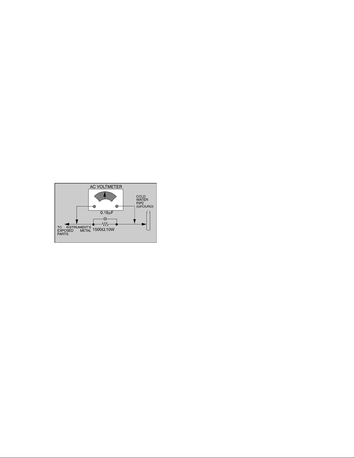
Leakage current hot check
1. Plug the AC cord directly into the AC outlet. Do not use
an isolation transformer for this check.
2. Connect a 1.5k, 10 watts resistor, in parallel with a
0.15F capacitors, between each exposed metallic part
on the set and a good earth ground such as a water
pipe, as shown in Figure 1.
3. Use an AC voltmeter, with 1000 ohms/volt or more
sensitivity, to measure the potential across the resistor.
4. Check each exposed metallic part, and measure the
voltage at each point.
5. Reverse the AC plug in the AC outlet and repeat each of
the above measurements.
6. The potential at any point should not exceed 0.75 volts
RMS. A leakage current tester (Simpson Model 229 or
equivalent) may be used to make the hot checks,
leakage current must not exceed 0.5 milliamp. In case a
measurement is outside of the limits specified, there is
a possibility of a shock hazard, and the equipment
should be repaired and rechecked before it is returned
to the customer.
2 Warning
2.1. Prevention of Electro Static
Discharge (ESD) to
Electrostatically Sensitive (ES)
Devices
Some semiconductor (solid state) devices can be damaged
easily by static electricity. Such components commonly are
called Electrostatically Sensitive (ES) Devices. Examples of
typical ES devices are integrated circuits and some fieldeffect transistors and semiconductor "chip" components.
The following techniques should be used to help reduce the
incidence of component damage caused by electro static
discharge (ESD).
1. Immediately before handling any semiconductor
component or semiconductor-equipped assembly, drain off
any ESD on your body by touching a known earth ground.
Alternatively, obtain and wear a commercially available
discharging ESD wrist strap, which should be removed for
potential shock reasons prior to applying power to the unit
under test.
2. After removing an electrical assembly equipped with ES
devices, place the assembly on a conductive surface such
as alminum foil, to prevent electrostatic charge buildup or
exposure of the assembly.
3. Use only a grounded-tip soldering iron to solder or unsolder
ES devices.
4. Use only an anti-static solder removal device. Some solder
removal devices not classified as "anti-static (ESD
protected)" can generate electrical charge sufficient to
damage ES devices.
5. Do not use freon-propelled chemicals. These can generate
electrical charges sufficient to damage ES devices.
6. Do not remove a replacement ES device from its protective
package until immediately before you are ready to install it.
(Most replacement ES devices are packaged with leads
electrically shorted together by conductive foam, alminum
foil or comparable conductive material).
7. Immediately before removing the protective material from
the leads of a replacement ES device, touch the protective
material to the chassis or circuit assembly into which the
device will be installed.
Caution
Be sure no power is applied to the chassis or circuit, and
observe all other safety precautions.
8. Minimize bodily motions when handling unpackaged
replacement ES devices. (Otherwise hamless motion such
as the brushing together of your clothes fabric or the lifting
of your foot from a carpeted floor can generate static
electricity (ESD) sufficient to damage an ES device).
3
Page 4
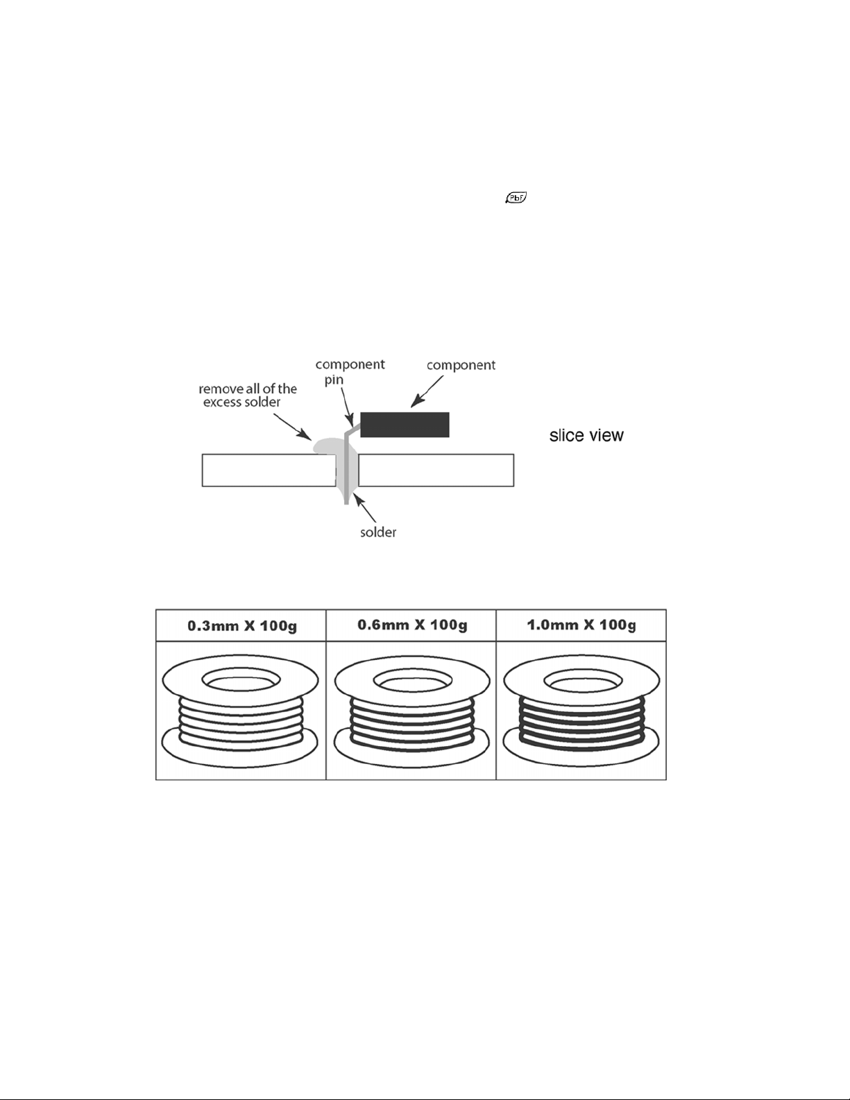
3 About lead free solder (PbF)
NOTE
Lead is listed as (Pb) in the periodic table of elements.
In the information below, Pb will refer to lead solder, and PbF will refer to Lead Free Solder.
The lead free solder used in our manufacturin g process and discussed below is (Sn+Ag+Cu).
That is Tin (Sn), Silver (Ag) and Copper (Cu) although other types are available.
This model uses Pb Free solder in it’s manufacture due to environmental conservation issues. For service and repair work, we’d
suggest the use of Pb free solder as well, although Pb solder may be used.
PCBs manufactured using lead free solder will have the “PbF” or a leaf symbol
CAUTION
• Pb free solder has a higher melting point than standard solder. Typically the melting point is 50 ~ 70 °F (30 ~ 40 °C) higher.
Please use a high temperature soldering iron and set it to 700 ± 20 °F (370 ± 10 °C).
• Pb free solder will tend to splash when heated too high (about 1100 °F or 600 °C).
If you must use Pb solder, please completely remove all of the Pb free solder on the pins or solder area before applying Pb
solder. If this is not practical, be sure to heat the Pb free solder until it melts, before applying Pb solder.
• After applying PbF solder to double layered boards, please check the component side for excess solder which may flow onto
the opposite side.
stamped on the back of PCB.
Suggested Pb free solder
There are several kinds of Pb free solder available for purchase. This product uses Sn+Ag+Cu (tin, silver, copper) solder.
However, Sn+Cu (tin, copper), Sn+Zn+Bi (tin, zinc, bismuth) solder can also be used.
4
Page 5

4 Receiver feature table
FEATURE / MODEL TC-26LX60L TC-32LX60L
LCD TYPE IPS (WXG A) IPS (WXGA)
LCD PANEL MAKER LG LG
CHASSIS LH58 LH58
SYSTEM NTSC NTSC
TUNING FST FST
STEREO MTS/SAP MTS/SAP
CATV USA CATV 181CH USA CATV 181CH
POWER SUPPLY AC120-127V, 60HZ AC120-127V, 60HZ
AV-IN 2 (RCA) 2 (RCA)
S-VHS-IN 2 2
COMPONENT VIDEO-IN VIDEO 1 / AUDIO 1 (RCA) VIDEO 1 / AUDIO 1 (RCA)
AV-OUT 1 (RCA) 1 (RCA)
HDMI 1 1
DVI NONE NONE
PC-INPUT NONE NONE
HEAD PHONE X X
PEAKS SYSTEM ----- ----GC SYSTEM MICRONAS VCTP MICRONAS VCTP
PROGRESSIVE X X
3D Y/CCOMB FILTER X X
SUB PIXCEL CONTROLER NONE NONE
GRS NONE NONE
AUDIO OUTPUT 10W + 10W 10W + 10W
SPEAKER SYSTEM UNDER/1 WAY - SPEAKER UNDER/1 WAY - SPEAKER
BASS/TREBLE X X
BALANCE X X
DTS NONE NONE
SURROUND X X
AUDIO OUT PERFORMANCE FAO FAO
SAFETY-STANDARD NOM NOM
STANDARD-ORGANIZATION E-STAR E-STAR
EMC (EMISSION) BETS-7 BETS-7
MECHANICAL ISTA ISTA
JPEG NONE NONE
MPEG4 NONE NONE
MPEG2 NONE NONE
ASPECT X X
CHANNEL BANNER NONE NONE
VIDEO PICTURE MEMORY NONE NONE
MULTI WINDOW NONE NONE
BLUE BACK (AV) NONE NONE
GAME MODE NONE NONE
GAME GUARD NONE NONE
OFF TIMER X X
AUTO SEARCH X X
DEMOSTRATION MODE ----- ----CLOSED CAPTION X X
V-CHIP X X
VESA COMPATIBLE COMPATIBLE
OSD LANGUAGE ENGLISH (US) / FRENCH / SPANISH ENGLISH (US) / FRENCH / SPANISH
REMOTE CONTROLLER EUR7613Z90R or EUR7613ZE0 EUR7613Z90R
CEC OF HDMI CONNECTION DIGA DIGA
PEDESTAL SWIVEL ONLY (NO TILTED) SWIVEL ONLY (NO TILTED)
SD SLOT FOR DL NONE NONE
Note:
Specifications are subject to change without notice or obligation.
5
Page 6
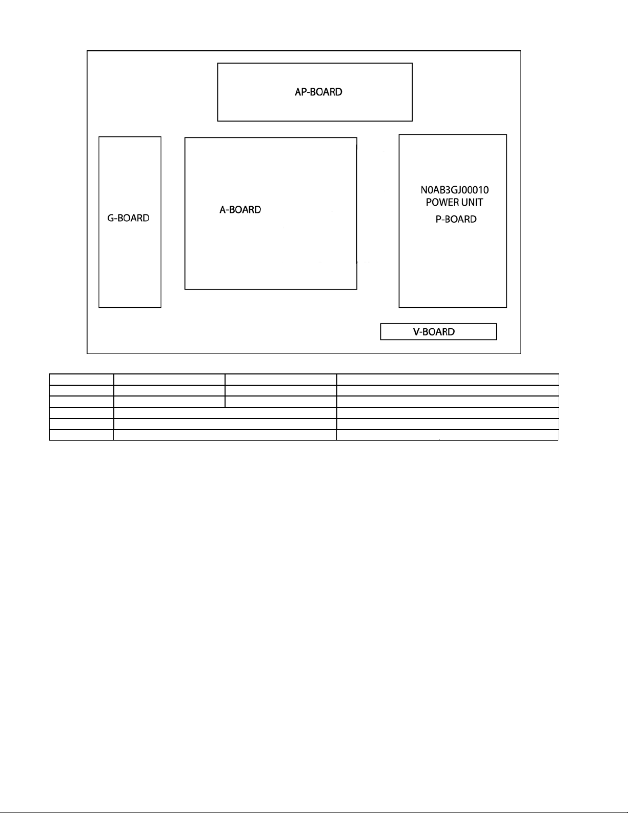
5 Chassis Board Layout
Board Layout
Board Name TC-26LX60L TC-32LX60L Function
A-Board TZRXN010MTJE TZRXN010MSJE Main (AV Switch, Audio, MCU, Global Core, AV connector)
AP-Board TZRXN020MSJE TZRXN020MSJE DC-DC
G-Board TNPA3784S Side Terminal
V-Board TNPA3749ACS Remote Reciever, LED
P-Board LSEP1221A1HB AC-DC
6
Page 7
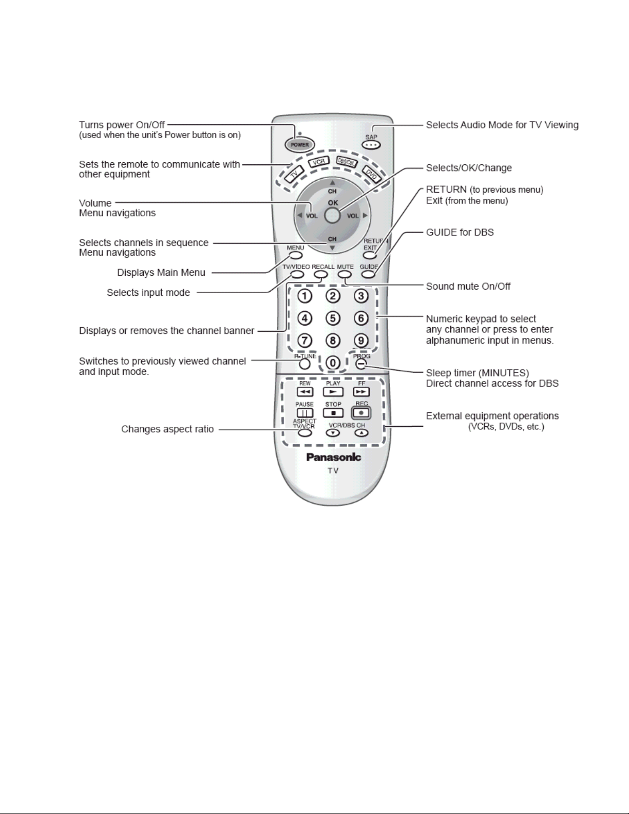
6 Location of controls (EUR7613Z90R or EUR7613ZE0)
7
Page 8
7 Service Mode
7.1. How to enter into adjustment
mode
While pressing [VOLUME-] button of the main unit, press
[RECALL] button of the remote control transmitter three times
in a row (within 2 seconds).
can be used to confirm the occurrence and to limit the
scope for the defective circuits. Also, when "the power fails
from time to time", display on the screen can be used to
confirm the occurrence and to limit the scope for the
defective circuits.
Any programmed channels, channels caption data and
some other user defined settings will be erased and return
to factory setting.
7.2. Adjustment method.....Use the
remote control.
“1” button...Main items Selection in forward direction
“2” button...Main items Selection in reverse direction
“3” button...Sub items Selection in forward direction
“4” button...Sub items Selection in reverse direction
7.3. Cancellation
Switch off the power with the [POWER] button on the main unit
or the [POWER] button on the remote control.
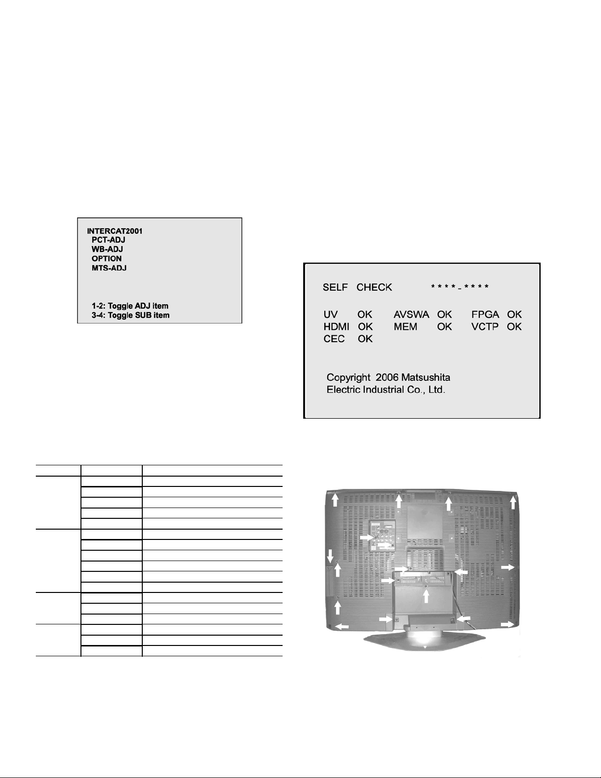
7.4. Contents of adjustment mode
• Value is shown as a hexadecimal number.
• Preset value differs depending on models.
• After entering the adjustment mode, take note of the value
in each item before starting adjustment.
Main Item Sub Item Remarks
PCT-ADJ COLOR Sub color Adjustment
R-Y-A recovery axis (R-Y)
B-Y-G Gain (B-Y)
BACK-L Sub-backlight
TINT Tint Adjustment
WB-ADJ (White
balance
adjustment)
OPTION OPTOO TV (for TV) (Not ADJ)
MTS-ADJ MTSIN RF Audio input level detection
B-CENT Blue Gain by test pattern (50% white)
G-CENT Green Gain by test pattern (50% white)
R-CENT Red Gain by test pattern (50% white)
B-GAIN Blue Gain by test pattern (100% white)
G-GAIN Green Gain by test pattern (100% white)
R-GAIN Red Gain by test pattern (100% white)
CEC-CHK For service only
EEP-COPY For service only
SEPAH Stereo separation Hi
SEPAL Stereo separation low
8.2. How to access
Access
Produce TV reception screen and, while pressing
[VOLUME -] button on the main unit, press [SLEEP] button
on the remote controller unit simultaneously.
Exit
Press the POWER button twice (off/on) to return to the
normal screen.
8.3. Screen Display
9 Disassembly Instructions
Back cover removal (screw location)
8 Troubleshooting Guide
8.1. Self-check function
When phenomena like "the power fails from time to time" or
"the video/audio fails from time to time" can not be
confirmed at the time of servicing, the self-check function
1. Remove all the screw from the back cover indicated with
arrows.
8
Page 9
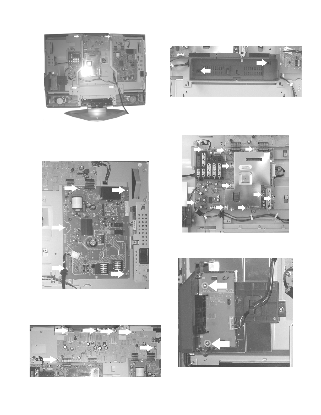
Without the back cover
1. First remove the two screws from each bracket one
located on top and one on the bottom.
P-Board Disassembly
then remove the screws indicated on the figure above
by arrows.
Bracket Disassembly
1. To remove the bracket shown above remove the screws
indicated on the figure above by arrow.
A-Board Disassembly
1. To remove the P-Board remove the screws indicated on
the figure above by arrows.
AP-Board Disassembly
1. To remove the A-Board bracket shown above remove
the screws indicated on the figure above by arrows.
G-Board Disassembly
1. To remove the G-Board shown above remove the screw
indicated on the figure by arrow.
1. To remove the AP-Board first lift the four connectors
9
Page 10
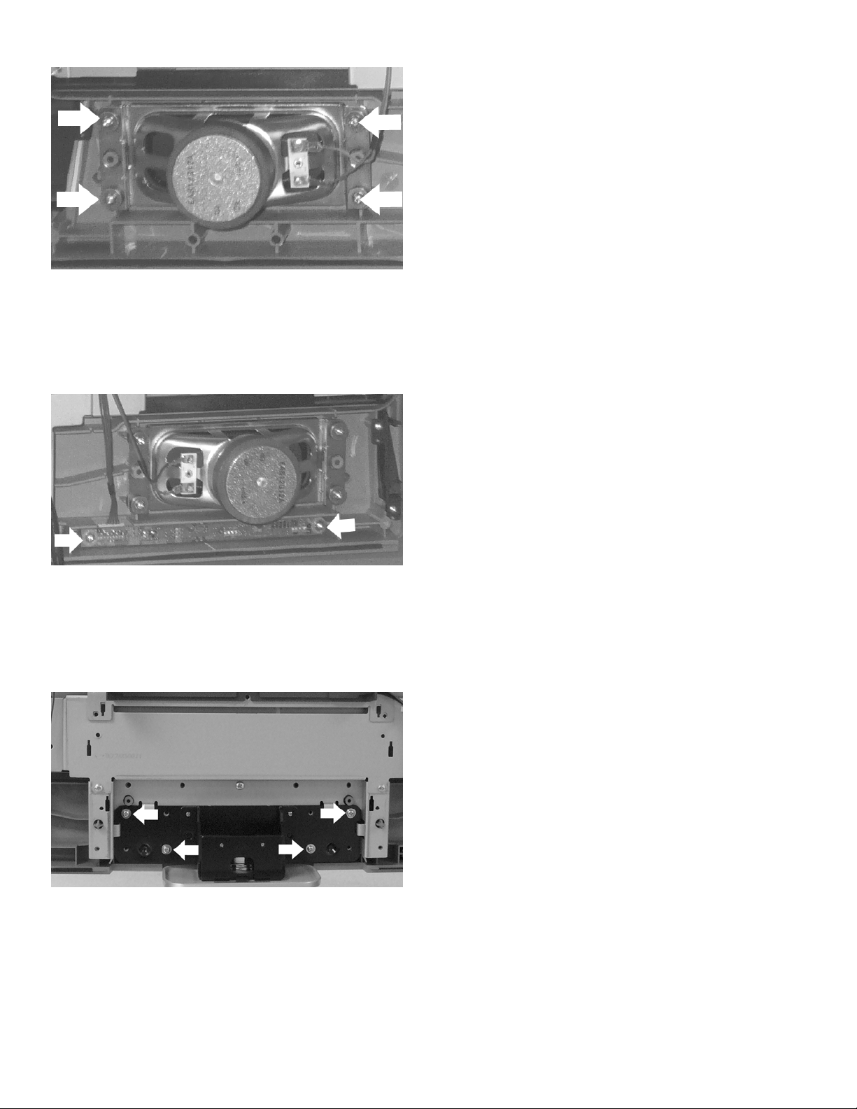
Speaker Disassembly
1. To remove the speaker remove the screws indicated on
the figure by arrows, each speaker is located on sides.
V-Board Disassembly
1. To remove the V-Board remove the screws indicated on
the figure by arrows.
Removing the pedestal
1. Lay down the unit so that the rear cover faces upward.
2. Remove the 4 screws.
3. Then remove the pedestal.
10
Page 11
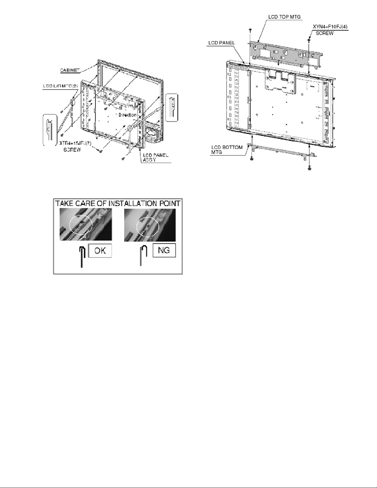
9.1. Removing the LCD panel
assembly and LCD L/R MTG
1. Remove the 4 screws.
2. Remove the LCD panel ass’y and LCD L/R MTG.
9.2. Removing the LCD panel and
LCD T/B MTG
1. Remove the 4 screws.
2. Remove the LCD panel and LCD T/B MTG.
11
Page 12
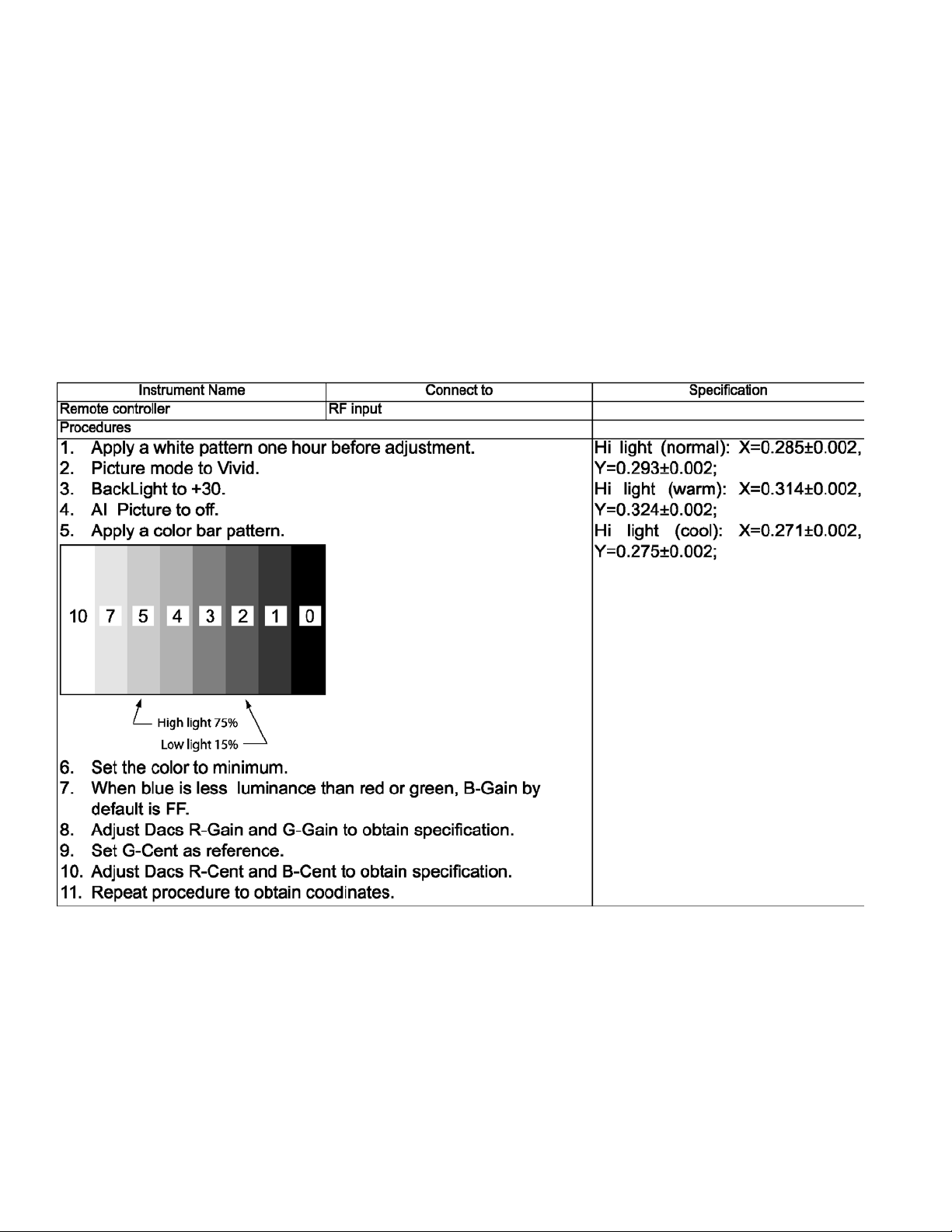
10 Measurements and Adjustments
10.1. White Balance Adjustment
12
Page 13
11 MTS circuit adjustment
The MTS circuit adjustment require two steps:
1. Input level adjustment.
2. Stereo separation adjustment.
Input level adjustment
Service DAC adjustment (MTSIN)
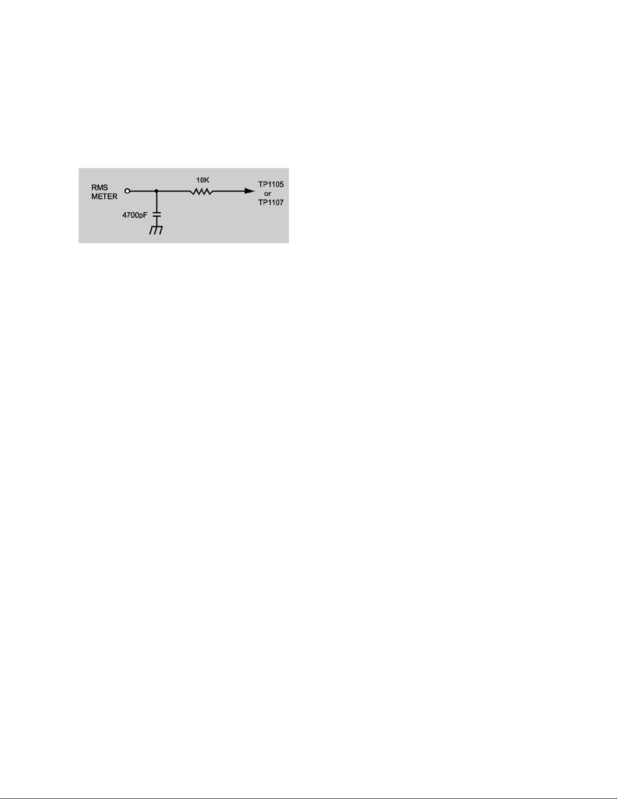
PREPARATION
1. Connect an RMS meter with filter jig as shown in figure
to TP1105 or TP1107 and gound.
2. Connect an RF sigal generator to the RF antenna Input.
PROCEDURE
1. Apply the following signal from the RF signal generator.
• Video: flat field, 30% modulation (70±5dB, 75 ohm
OPEN, P/S 10dB).
• Audio: 300Hz, 100% modulation, monaural
(70±5dB, 75 ohm OPEN, P/S 10dB.) Make sure that
the 75µs pre-emphasis is OFF.
2. Adjust the MTS input level adjustment “MTSIN” data
until the RMS voltage measured is 106mVrms ±
6.0mVrms.
Stereo separation adjustment (SEPAH)
PREPARATION
1. Connect an R.F. signal generator to the RF antenna
input.
2. Connect a scope to TP1104 or TP1106 and ground.
PROCEDURE
1. Select stereo mode in audio menu.
2. Apply the following signal from the RF signal generator.
• Video: flat field, 30% modulation.
• Audio: 300Hz, 30% modulation, stereo (left only)
(70±5dB, 75 ohm OPEN, P/S 10dB.)
Note: After setting 30% modulation with P.L. SW
and N.R. SW OFF, turn P.L. SW and N.R. SW ON.
3. In service mode, adjust the MTS Low-Level separation
adjustment “SEPAL” data until the amplitude displayed
on the scope is minimum.
4. Apply the following signal from the RF signal generator.
• Video: flat field, 30% modulation.
• Audio: 300Hz, 30% modulation, stereo (left only)
(70±5dB, 75 ohm OPEN, P/S 10dB.)
Note: After setting 30% modulation with P.L. SW
and N.R. SW OFF, turn P.L. SW and N.R. SW ON.
5. Adjust the MTS High-level separation adjustment
“SEPAH” until the amplitude displayed on the scope is
minimum.
6. Repeat above steps 2 through 5 until the amplitude is at
minimum for both signals.
13
Page 14
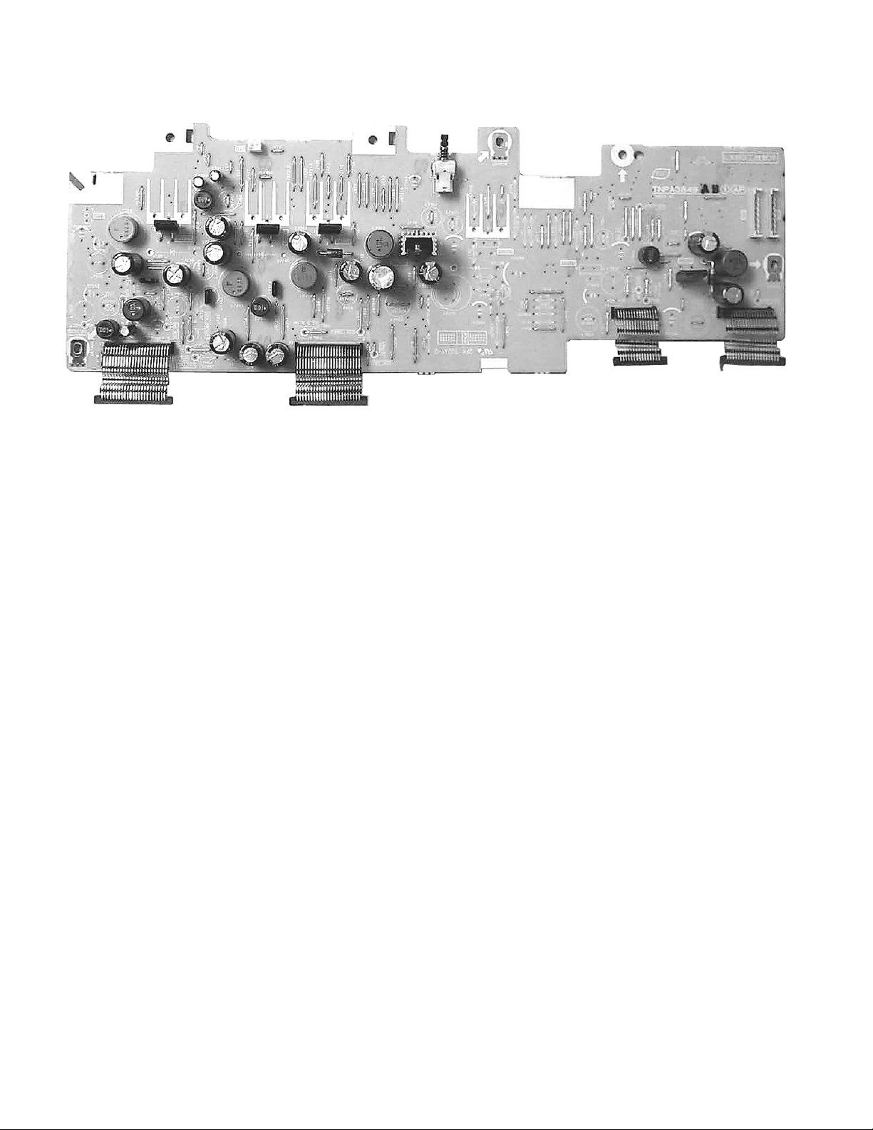
12 Boards Assemblies
12.1. AP-Board
14
Page 15
12.2. A-Board
15
Page 16

12.3. P-Board
16
Page 17

12.4. G-Board
17
Page 18

12.5. V-Board
18
Page 19

13 Block Diagram
2
T
O
H
N
B
13.1. Block Diagram for P and AP (DC-DC CONV.) (1 of 2)
2
AP
DC-DC CONV.
1
1
1
IC7218
SOUND_20V
+20V
IC7205
MAIN_5V
+5V
IC7209
SUB9V
+9V
10V OVP
*D7223
(+15V)
24V OVP
D7203
(+27V)
5
5
5
*D7224
D7204
2
Q7301
SOUND+18V ON
2
Q7303
MAIN+5V ON
2
UNREG_30V
MIX
10V,24V,SUB+9V
MAIN+5V,MAIN+9V
SOUND VCC,PANEL VCC
OVP DET
Q7204-Q7207
O.V.P, DET CIRCUIT
(DET:AC RELAY OFF)
SOUND_20V OVP
D7303
(+22V)
D7301
(+7.5V)
D7601
D7602
5V OVP
L:NORMAL
H:ABNORMAL
PANEL_Vcc OVP
D7703
(+18V)
Q7
SHOR
10V,
SOU
S
MAIN9V
D7452
D
(+13V)
D7704
D7304
D7302
(+13V)
D7404
D7403
9V OVP
IC7210
MAIN_9V
+9V
IC7212
+9V
Q7701
2
5
*Q7450
MAIN+9V ON
2
5
1
PANEL_Vcc(12V)
1
PANELVCC_ON
1
K
KEY SCAN
Note:
K-board is included in the control panel assy.
0
KEY SCAN
/
P
POWER UNIT
LSEP1221AHB
Exchange board only
.
1
3
-
CN1
AC CORD
K1
1
CN3
1
2
3
4
5
11
12
13
CN2
1
2
3
4
5
6
7
8
9
,
KEY
RELAY
SUB_ON
INV 24V
INV 24V
INV 24V
INV 24V
INV 24V
INV 24V
INV 24V
INV 24V
INV 24V
TO
LCD PANEL
(INVERTER)
TO
LCD PANEL
(INVERTER)
24V
24V
24V
10V
10V
7VS
INV 24V
INV 24V
INV 24V
INV 24V
INV 24V
INV 24V
INV 24V
INV 24V
AP6
1
AP2
1
2
3
4
5
11
12
13
AP1
1
2
3
4
5
6
7
8
9
AP3
2
3
6
7
*Q7224
*Q7223
RELAY ON/OFF
AP7
1
2
3
4
+
TC-26/32LX60L Block Diagram (1 of 2)
*
)
! "#$ %& ' (
*34567,89:;9<77=4;7>?7@79AB7)@7C!74=7"D7E+F"&GH&IG?7E+F#"GH&IG
19
Page 20

13.2. Block Diagram for P and AP (DC-DC CONV.) (2 of 2)
O
2
AP3
A3
SOUND_VCC
2
SOUND_VCC
*D7220
N
UNREG_30V
MIX
,SUB+9V
V,MAIN+9V
VCC,PANEL VCC
VP DET
204-Q7207
DET CIRCUIT
C RELAY OFF)
SOUND_20V OVP
D7303
(+22V)
D7301
(+7.5V)
D7601
D7602
5V OVP
D7304
D7302
(+13V)
D7404
D7403
9V OVP
IC7210
1
+9V
IC7212
PANEL_Vcc(12V)
1
+9V
Q7701
PANELVCC_ON
MAIN_9V
2
5
*Q7450
MAIN+9V ON
2
5
1
0
/
.
-
L:NORMAL
H:ABNORMAL
(+13V)
PANEL_Vcc OVP
D7703
(+18V)
Q7210
SHORT SOS
10V, BT30V
SOUND VCC,PANEL VCC
SHORT SOS DET
MAIN9V OVP
D7452
D7453
D7704
D7207
Q7702
PANELVCC_ON
Q7211
SHORT SOS
D7206
(+15V)
Q7208
24V DET
MAIN_9V
MAIN_5V
SOUND_16V
DC-DC ON/OFF CONTROL
Q7508
24V DET
SOUND VCC SHORT SOS
Panel Vcc SHORT SOS
D7470
Q7212
10V SHORT SOS
D7208
BT 30V SHORT SOS
D7469
D7472
Q7214
24V DET
D7471
D7474
D7473
Q7805
INV_ON
Q7806
INV_ON
POWER SWITCH
*SW7203
PUSH
3
BT_30V
7
MAIN_9V
17
MAIN_9V
18
19
MAIN_9V
MAIN_5V
21
MAIN_5V
22
A4
AP4
TV_SOS
1
3
STB_7V
6
TV_MAIN_ON
7
ALL_OFF
TV_SUB_ON
8
11
PANEL_12V
12
PANEL_12V
KEYSCAN
14
15
PANELVCC_ON
INV_ON
18
SUB_9V
22
22
SUB_9V
,
+
TC-26/32LX60L Block Diagram (2 of 2)
*
)
! "#$ %& ' (
*34567,89:;9<77=4;7>?7@79AB7)@7C"74=7"D7E+F"&GH&IG?7E+F#"GH&IG
20
Page 21

14 Schematic Diagrams
14.1. Schematic Diagram Notes
21
Page 22

14.2. Reference of PDF links color
22
Page 23

14.3. A-Board (1 of 7) Schematic Diagram
2
1
0
/
.
-
,
+
*
)
! "#$ %& ' (
)F*J)K,777777!74=7'777777EL@0I&'')-M).77777E+F"&GH&IG?7E+F#"GH&IG
23
Page 24

14.4. A-Board (2 of 7) Schematic Diagram
2
1
0
/
.
-
,
+
*
)
! "#$ %& ' (
)F*J)K,777777"74=7'777777EL@0I&'')-M).77777E+F"&GH&IG?7E+F#"GH&IG
24
Page 25

14.5. A-Board (3 of 7) Schematic Diagram
2
1
0
/
.
-
,
+
*
)
! "#$ %& ' (
)F*J)K,777777#74=7'777777EL@0I&'')-M).77777E+F"&GH&IG?7E+F#"GH&IG
25
Page 26

14.6. A-Board (4 of 7) Schematic Diagram
2
1
0
/
.
-
,
+
*
)
! "#$ %& ' (
)F*J)K,777777$74=7'777777EL@0I&'')-M).77777E+F"&GH&IG?7E+F#"GH&IG
26
Page 27

14.7. A-Board (5 of 7) Schematic Diagram
2
1
0
/
.
-
,
+
*
)
! "#$ %& ' (
)F*J)K,777777%74=7'777777EL@0I&'')-M).77777E+F"&GH&IG?7E+F#"GH&IG
27
Page 28

14.8. A-Board (6 of 7) Schematic Diagram
2
1
0
/
.
-
,
+
*
)
! "#$ %& ' (
)F*J)K,777777&74=7'777777EL@0I&'')-M).77777E+F"&GH&IG?7E+F#"GH&IG
28
Page 29

14.9. A-Board (7 of 7) Schematic Diagram
2
1
0
/
.
-
,
+
*
)
! "#$ %& ' (
)F*J)K,777777'74=7'777777EL@0I&'')-M).77777E+F"&GH&IG?7E+F#"GH&IG
29
Page 30

14.10. AP-Board (1 of 3) Schematic Diagram
2
1
0
/
.
-
,
+
*
)
! "#$ %& ' (
)@F*J)K,7777777!74=7#777777EL@)#($N),7777777E+F"&GH&IG?7E+F#"GH&IG
30
Page 31

14.11. AP-Board (2 of 3) Schematic Diagram
2
1
0
/
.
-
,
+
*
)
! "#$ %& ' (
)@F*J)K,7777777"74=7#777777EL@)#($N),7777777E+F"&GH&IG?7E+F#"GH&IG
31
Page 32

14.12. AP-Board (3 of 3) Schematic Diagram
2
1
0
/
.
-
,
+
*
)
! "#$ %& ' (
)@F*J)K,777777#74=7#777777EL@)#($N),7777777E+F"&GH&IG?7E+F#"GH&IG
32
Page 33

14.13. V-Board Schematic Diagram
2
1
0
/
.
-
,
+
*
)
! "#$ %& ' (
OF*J)K,7777777EL@)#'$N)+7777777E+F"&GH&IG?7E+F#"GH&IG
33
Page 34

14.14. G-Board Schematic Diagram
2
1
0
/
.
-
,
+
*
)
! "#$ %& ' (
/F*J)K,7777777EL@)#'($7777777E+F"&GH&IG?7E+F#"GH&IG
34
Page 35

15 Printed Circuit Boards
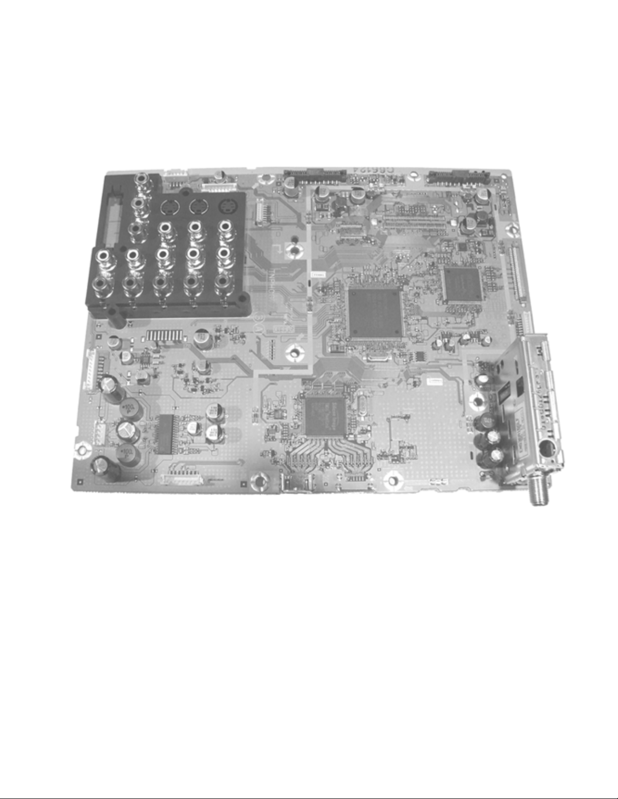
15.1. A-Board Top Side
2
JS2004
C2130
C2130
L2001
1
0
JS2005
JS2013
A1
C1180
18
C4133
C4134
R4238
R4321
C2134
C2135
C2136
C2137
D2002
A7
A7
1
4
C2127
C2140
R2101
C2181
C2180
C2126
C2140
L2001
R2099
R2100
C2124
C2122
C2119
C2114
C2178
C2179
C2125
32
IC2001
IC2001
C2113
C2101
C2132
1
C2102
C2110
R2115
R2140
R2114
L2005
C2103
R2107
R2139
C2173
R2103
R2104
R2159
C2175
L2003
C2223
C1179
C1178
C1143
A1
JS2021
JS2016
D2003
C2131
C2129
C2128
R2102
L2002
L2002
C2138
17
JS2014
C2133
16
C2111
C2106
C2109
R2108
R2105
R2106
R2160
C2139
C2131
Q2312
Q2313
A6
A6
1
C2100
R2153
C2157
JS2015
C2142
R2122
R2120
Q2020
R2121
Q2020
C2068
R2161
Q2030
R2110
R2314
Q2306
R2310
R2313
R2309
Q2312
Q2305
R2382
R2306
R2307
Q2313
C2375
Q2305
R2381
R2383
Q2303
JS2301
R2304
D2309
R2303
D2005
Q2303
R2116
Q2306
C2367
JS2020
9
R2154
C2172
C2141
IC2005
8
1
R2117
IC2005
R2113
4
5
C2145
C2144
C2146
C2147
R2112
R2152
R2096
R2097
Q2019
Q2030
Q2019
D2004
C2368
JS2306
R3020
/
C5006
R5025
R5006
R5002
C5004
C5002
R5128 R5129
Q5002
R5004
Q5002
C5023
FL5001
R5060
R5115
19
.
JK5002
1
C5005
R5024
Q5001
C5001
-
19
JK5001
JK5001 JK5002
1
,
ZA4006
L5009
R5015
D5002
L5013
R5016
R5116
L5008
D5004
R5017
D5006
FL5005
R5018
D5008
R5019
D5010
R5020
37
D5013
R5021
D5018
R5022
D5020
Pad
Thermal
R5005
C5003
C5010
Q5001
R5001
R5003
FL5002
R5007
D5001
72
R5008
R5009
D5003
IC5004
D5005
73
R5010
D5007
R5011
D5009
R5012
D5012
R5013
C5009
D5016
R5014
D5019
C5053
Q5019
Q5019
R5094
R5096
D5023
R5102
Q5018
Q5018
R5095
Q5020
R5093
R5098
R5100
C5054
C5055
R5097
Q5021
R5101
R5099
+
C003
AGCADJ
C002 C003
C002
+B
C014
TP2200
TP2200
*
)
ZA4005
R1187
C009
AGCCONT
APANAMALAK
JS3079
JS3080
JS3081
JS3082
JS3083
AEAFAG
AH
C4145
+
C4120
L4016
IC4001
L4014
C4111
R4266
C4064
C4072
X4001
R4082
C4071
R4326
C4182
R4325
C4183
R4262
C4177
R4261
C4176
R4260
R4259
R4211
R4212
R4258
C1169
R4257
C1168
R4011
R1172
R1171
104
5
8
IC1102
IC1102
1
4
C1853
C1845
C1843
R003
Q001
C010
TP1104
Q001
R005
R004
JS002
SIF-OUT
VIDEO
AUDIO
R5054
C5050
C5049
R5119
FL5007
1
4
Q5023
R5055
Q5023
R5061
R5062
R5064
C5018
36
C5019
D5021
D5025
D5027
Q5020
Q5021
L001
C004
TU001
TU001
C5051
IC5005
IC5005
R5114
L5011
FL5003
5
R5066
R5068
R5070
7
C5024
C5027
C5022
R5063
R5065
R5105
R5106
ZA4007
L001
BT
C5042
C5025
C5026
C5031
C5033
C5028
C5040
C5041
1
R5111
144
R5083R5084
IC5004
R5075
R5073
R5069
R5067
C5030
R5130
R5131
Q5024
Q5024
C015
R010
R009
RF-AGF
SCL
IFOUT
R5087
R5085
R5086
R5081
R5082
109
108
L5007
C5038
R5078
R5079
R5080
X5001
R5077
C5034
R5091
R1192
R1190
Q1152
R1186
Q1152
TP1105
C011
JS004
C008
JS003
C016
R001
SDA
AFT
BTL
1
4
A8
A8
S3002
S3001
C2143
S3021
C2158
S3022
S3020
S3019
10
S3014
A21
1
A21
C3064
Q3002
Q3001
Q3002
R3021
Q3003
C3067
R3025
Q3001
R3026
R3030
R3028
R3027
R3033
Q3004
R3032
Q3004
AJ
JS3077
JS3078
ABACAD
S3017
S3015 S3016
S3010S3011
S3009
R3023
S3005
Q3003
S3003 S3004
C3065
3
A
C4142
JK3002
JK3002
TNPH0677
S3008
S3007
A15
1
R1236
R1237
SUFFIX
IC4005
ZA4003
D1809
C1891
C1890
D4801
R4806
R4803
D1816
24
IC4801
IC4801
1
R4807
56
A12
R4760
CL4656
CL4533
A12
CL4530
CL4529
R4640
R4639
R4644
R4643
R4650
R4188
110
C1874
D1815
+
L1811
C1875
D1813
ZA4004
R4015
R4005
Q4001
R4042
R4040
Q4001
C4033
L4008
C4113
R4050
R4048
R4197
R4053
R4055
R4057
R4063
R4061
R4147
C4055
R4047
R4065
R4148
53
C4065
C4066
C4067
R4254
R4255
105
R4079
R4324
R4077
R4323
C1851
4
5
C1852
4
5
C1844
10
A14
R4049
C4056
C4058
52
C4060
R4246
R4248
R4247
R4080
C4104 C4105
L4009
C1849
3
IC1805
1
R1821
R1822
C1847
C1850
C1848
IC1804
1
R1819
C1846
R1820
C1842
C4046
R4251
IC4001
C4059
R4245
C4049
C4054
C4050
R4755
R4757
C4068
R4244
C4057
R4756
R4752 R4753
R4754
R4758 R4759
L4007
C4095
C4094
L4011
R4202
C4089
C4075
R4200
IC1805
R4198
C4093
L4010
R4196
R4098
R4194
C4092
C4101
3
C4102
L4012
R4142
R4146
C4166
R4192
IC1804
C4091
R4224
ZA4008
1
A14
R4018
R4026
R4023
R4044
R4029
R4039
R4032
R4195
C4045
R4751
R4750
73
R4025
R4028
R4031
R4034
C4106
R4021
C4036
C4037
1
R4213
R4190
R4004
R4009
208
L4005
L4004
C4031
C4020
C4030
C4023
C4018
R4280
R4278
C4017
C4027
C4015
R4275
R4273
C4004
R4272
C4003
R4810
C4025
L4003
C4024
C4021
C4148
L4002
C4019
C4029
R4001
R4003
R1155
R1156
C1177
157
CL4024
CL4015
C4032
CL4014
156
R4012
C4042
C4035
C4034
L4006
L4001
CL4020
C4009
C4022
CL4021
CL4022CL4023
R4223
R4038
C4163
R4222
R4218
C4165
C4164
R4130
R4133
C4099
C4090
C4097
C4088
72
108
C4074
C4087
C4084
109
R4126
R4127
1
A2
1
Q1150
R1161
Q1150
C4160
R1169
C4162
R1170
R1166
R4267
R4214
R4230
C4083
R4120
R4128
R4121
C4085
IC4004
Q4120
D4121
C4161
R4220
C4159
R4201
R4229
Q4120
R4116
R4092
R4217
R4119
C4082
C4080
R4084
R4281
R4110
37
36
R4108
R4083
C4078
R4210
R4209
R4104
C4077
C4076
1
144
R4107
R4109
R4111
R4113
R4115
R4123
R4125
R4117
IC4004
R4204 R4205
R4206
R4207 R4208
FL4001
FL4002
FL4003
1
1
A2
25
48
Q4801
Q4801
C4806
R4808
Q1145
Q1145Q1146
Q1146
R1157
R4219
Q4121
R4282
C4158
Q4121
R4093
R4106
R4105
R4124
C4118
C4096
C4098
C4157
C4100
R4136
R4140
R4141
14
8
R4129
C4103
IC4005
R4215
R4118
C4156
1
7
C4086
R4114
C4153
R4131
R4135
R4132
C4152
C4146
R4090
C4151
C4115
Q4003
Q4002
R4087
Q4003
Q4002
C4150
C4139
C4810
C4811
R4814
R4815
ZA4030
32
S3018
JS2022
S3013
S3012
V1
S3006
V2
R1193
D1102
R1864
MONOUT
A15
8
R1239
TP1821
R1846
C1889
1
A5
A5
C1859
5
L1808
C1856
A16
L1807
8
C1855
A16
R1854
C1896
C1895
C1854
JS2023
1
TP1831
TP1823
TP1816
C1831
C1832
A3
23
22
C1830
TP1830
A3
C1888
+
D1818
L1813
Q1142
Q1143
Q1141
55
C4175
JS4079
JS4078
L4023
L4022
JS4076
JS4077
C4174
JS4050
CL4580
JS4049
R4658
R4652
R4665
R4664
R4659
R4656
R4663
R4662
R4654
R4657
FL4021
JS4080
C4173
JS4081
L4021
1
C1824
C1867
C1868
C4140
C1899
C1898
C022C023
TP1832
2
C1881
C1882
C1880
L1812
C4816
C4817
R4820
R4821
C1825
R1880
JS1801
JS1802
C1823
L1809
L1810
C1866
IC1808
R1859
IC1808
C1897
R022
R023
1
R1148
R1149
C1141
Q1142
R1144
Q1143
R1146
Q1141
R1145
R1142
Q1144
R1147
Q1144
Q1811
C4119
C1906
R1877
R1878
D1825
Q1811
R1876
Q1810
R1874
R1875
Q1810
A4
23
22
A4
ZA4001 ZA4002
2
1
D1821
D1822
C1900
C1901
TP1829
R1860
TP1815
! "#$ %& ' (
)F*J)K,7777777EL@0I&''F#7777EJ@7777E+F"&GH&IG?7E+F#"GH&IG
35
Page 36

15.2. A-Board Bottom Side
2
1
0
/
.
-
,
+
*
TU001
AGCADJ
+B
C002
C003
JK5001
R5023
JK5002
R5026
TP2200
JK5001
R5127
JK5002
C003
TP2200
TP5001
TP5003
R5045
R5044
TP5002
TP5004
C002
R4235
C4126
C4125
R5132
R5043
L5003
D5011
R5042
L5004
R5039
R5038
D5015
C5008
R5035
C5011
C5007
R5125
R5126
R5030
TP5006
TP5005
4
1
IC5002
TP5010
R5031
IC5002
C5012
8
5
R5041
R5040
R5036
L5006
L5005
D5017
D5014
R5120
3
Q5008
C5014
Q5008
R5121
4
C5015
R5052
R5048
TP5009
R5103
D5024
A
C2162
R2109
JS2011
L2001
L2001
C2130
C2130C2131
RF-AGF
BT
TU001
IFOUT
L001
L001
C026
Q5025
Q5025
Q5022
5
Q5022
4
IC5001
1
C5057
8
R5088
C5020
R5058
C5029
IC5001
C5056
R5034
Q5004
R5028
R5032
C5016
C5017
TP5011
Q5009
C5013
Q5009
1
R5122
FL5006
IC5003
R5123
R5049
R5117
R5053
5
R5071
C5021
R5072
R5057
IC5003
R5104
R5074
D5026
3
TP2008
D2001
C2115
1
TP2009
R2098
C2112
R2111
C2120
C2163
C2116
C2117
R2155
R2156
C2118
C2140
L2002
C2140
4
A7
A7
SCL
AFT
SIF-OUT
BTL
AGCCONT
AUDIO
SDA
R2210
R2211
R2212
R2209
24
R2220
IC2202
IC2202
+
1
TP1108
C2211
C2212
C2201
C2213
CL5001
C5060
R5109
C5032
C5036
L5010
C5048
Q5004
C5047
Q5003
C5046
Q5003
R5124
R5113
R5029
C5045
R5033
R5027
C5044
R5110
D5022
C5043
R5112
C5039
R5076
C5037
C5035
TP5008
R5118
FL5004
L5012
C5061
C4135 C4136
R4322
R4239
JS2012
L2002
C2131
VIDEO
TP1107
C2221
C2222
C2214
C2215
SUFFIX
Q2307
C024
R024R025
C025
TP1705
TP1707
TP1709
TP1708
TP1710
TP1706
C4181
C4178
TP077
C4179
TP1106
R2208
JS2018
JS2019
C2206
C2205
C2220
13
C2219
C2218
12
+
C2217
C2216
Q1149
R1173
R1195
R1194
R5108
IC4002
R5107
C4070
C4069
TP3
TP7
TP5
TP9
TP3
TP5
TP7
TP9
TP0
TP2
TP4
TP6
TP8
TP8
TP0
TP2
TP4
TP6
Q1149
TP1101
R1167
D1101
R4225
R4060
R4014
R4008
R4264
D4122
IC4002
R4243
R4221
R4075
R4066
R4073
R4191
R4199
R4263
R4252
R4007
R4112
R4253
C4061
R4265
C4062
C4073
TP078
C4180
TP081
TP079
R4143
R4193
C4170
C4168
C4167
R4138
R4139
TP056
TP1
TP1
R4242
R4241
TP1176
C4053
R4250
R4249
CL4018
R4240
C4041
C4051
C4044
C4109
C4052
JS4082
C4110
C4043
C4040
C5058
Q1153
R1189
Q1153
C4081
TP068
TP062
TP074
TP065
TP071
TP069
TP075TP076
TP063
TP066
TP072
TP070
TP064
TP073
TP067
R4144
R4228
R4145
TP054
C4169
TP055
R4122
1
R1159
7
CL4016
CL4017
CL4019
R4232
R4069
R4059
R4072
R4081
R4227
R4058
R4256
C4001
C4026
R4271
R4274
C4028
R4276
R4279
R4010
C4039
JS4075
R4062
C4038
JS4074
R1188
R4149
R4150
D4001
PbF
SEE REVERS E FOR
TNPH0677
D3002
Q3006
D3023
R3100
C4116C4117
R4231
D2304
D2305
D2301
R2308
R3031
C3071
C3072
L3002
L3001
C3070
C3069
C3068
R3029
R3024
R3022
R4237
C4131 C4132
R4320
D3001
R3103
R3019
R3104
FL3030
1
JK3002
R2323
R2319
R2320
R2321
C2369
Q2307
Q2308
C2310
C2104
R3053
R3052
C2314
Q2308
C2105
FL3052
1
R3051
C2176
R3043
FL3031
R3034
1
D3024
D3003
1
R3109
D3007
D3008
R3111
D3009
R3117
D3013D3014
R3119
D3015
D3019
R3126
D3020
D3032
R3128
D3022
R3005
FL3033
R3108
D3025
FL3034
D3026D3027D3028
1
FL3036
FL3037
1
D3029
FL3049
D3030D3031
1
FL3050
1
D3021
R1700
C4809
R1701
R1702
TP1711
TP1713
TP1712
C4808
C4128
TP1701
TP1703
TP1702
TP1704
R4203
C4079
TP082
R4189
R4216
R4089
TP084
R4094
R4101
R4100
R4103
R4102
R4097
4
R4099
TP086
R4318
IC1101
R1158
IC1101
R4074
R4071
R4078
C4002
R4813
C4010
R4809
C4011
C4012
C4013
C4016
R4277
C4006
C4007
C4149
+
R4064
R3042
R3041
R3037
R3038
R3039
Q3006
C3076
R3102
C3075
R3036
R3035
C3074
C3073
R3101
R3131
Q3008
R3137
Q3008
C2171
R2131
C2160
R3112
R3006
R2132
C2161
C2121
C2123
R3110
R3007
R2118
1
C2148
R3010
R3116
R3118
R3011
R3120
R3012
R3016
R3127
R3017
R3125
R3130
R3002
R3129
R3001
IC2007
L4904
C4807
C4121C4122
R4233
R4226
C4147
R4269
R4268
C4155
R4134
C4154
L4015
R4137
C4129
C4112
1
8
IC4003
5
C4171
IC4003
C4172
C2374
R4317
R4666
Q1147
R4667
R1160
Q1147
C1167
R1165
14
Q1148
R1162
R1163
R1168
8
R1164
Q1148
R4812
R4811
C4014
C4005
C4008
R4746
C4114
R4744
R4748
R4747
C4137
C3077
Q2031
R3040
Q3007
Q2031
Q3007
Q2032
Q2032
C4143
R3132
Q3009
Q3009
Q3005
Q3005
R3133
R3134
C3080
C3078
C3135
R3136
R3135
R3138
C3079
C3081
R2141
R2142
R2137
R2138
R2149
R2148
C2170
R2135
R2136
C2174
R2150
R2151
R2143
32
17
IC2006
16
1
R2119
R2123
R2124
R2125
R2126
R2127
R2130
R2128
R2129
C2149
C2150
C2151
C2152
C2153
C2154
C2155
C2156
JK3002
C2165
C2164
D3018
C2370
JS2017
L2004
R2144
R2147
C2167
5
R2145
C2166
IC2007
C2107
R2146
1
R1839
R1838
R1843
C1878R1850
C1873
R1872
R1841
TP1826
7
C1876
C1877
R1840
D1808
R1852
R1866
R1867
R4655
JS4048
A12
JS4041
JS4039
JS4038
JS4046
JS4047
JS4045
C5059
C4141
L4801
R4762
C4802
C4801
R4761
C4803
C4804
R1848
R4801
R4804
R4763 R4764
R4802
R4805
C4805
R1845
C1905
C4127
C4130
R4236
C2372
R1232
R1238
TP1202
R3003
C3062
C2169
R3105
C2168
D3006
D3012
D3004
C2371
IC2006
R2134
R2133
C2159
R3124
R3014
D3017
R3015
R3123
C2108
1
R4819
C4814
C2177
C4815
R4818
C1865
R1842
C1872
IC1806
IC1806
R4319
Q1215
TP1203
FL3032
FL3048
JS4073
C1879
R1844
C4123C4124
Q1215
R1235
R3004
C1840
Q1802
Q1802
R1816
R1818
C1839
R1817
1
TP1811
TP1809
D4123
TP4008
CL4554
TP1201
JS4072
JS4044
Q1807
C2373
C1884
C1885
R1851
1
C1886
R1847
C1887
TP1828
7
C1892
R1849
R021
+
R4234
R1233
R1234
Q1216
Q1216
R1228
R1229
R1230
R1231
TP1205
TP1207
TP1206
TP1208
R1873
Q1801
Q1801
C1836
C1871
C1870
C1869
TP1810
C1907
TP1812
D1802
R1868
R1858
R1857
D1823
C1841
C1835
IC1803
R1811
C1837
R1869
R1856
R1180TP1818
R1181
R1183
R1184
R1185
R1179
R1178
R1813
C1181
R1814
Q1151
IC1803
C1838
Q1151
R1812
TP1813
C1821
C1834
TP1805
C1822
D1810
D1811
L1805
R1815
TP1204
TP1040
D1824
TP1814
TP1042
TP1806
TP1808
D1801
D1803
R1863
D2006
TP1807
R1865
C1893
R1871
C1894
R1853
R1870
TP1036
Q1809
Q1809
D3870
R3875
Q3860
Q1808
C1902
Q1807
C1904
C1883
IC1807
R020
R3862
R3861
Q3860Q3861
R1879
Q3861
Q1808
R3863
R3880
C1903
R1861
R1862
C3860
D3862
Q3862
R3876
Q3862
R3879
R3866
TP1825
R3864
D3866
D3863
R3873
R3877
D3868
C4138
D3860
D3861
R3860
R3874
R1143
D3869
C1864
IC1807
R1836
R1837
TP1817
TP1024
TP1820
C1826
C1827
D3867
R3867
C020 C021
C1833
L1806
TP1819
R3878
R3865
JS1804
JS1805
JS1806
JS1803
D3864
D3865
TP1822
C1829
C1828
TP1021
TP1824
1
C4812
C4813
R4817
R4816
R3106
R3107
D3005
MONOUT
R1174
R1175
TP4061
TP1074
V2
TP1077
C1857
D3010
R3113
R3008
R3114
V1
R3115
R3009
D3011
D3016
R3122
R3121
R3013
Q1806
TP1078
Q1803
C4144
TP1076
Q1803
R1823
R1827
TP1075
R1825
R1824
R1826
R1176
Q1804
Q1804
R1177
R1835
R1833
Q1806
TP1079
D1812
R1834
R1828
R1829
R1830
D1819
R1832
D1820
Q1805
R1831
C3063
Q1805
C1858
FL1805
TP052
C1863
JS1810
FL3035
TP051
FL1804
C1862
JS1809
TP050
C1861
JS1808
FL1803
TP049
1
C1860
TP053
JS1807
FL1802
)
! "#$ %& ' (
)F*J)K,7777777EL@0I&''F#7777*JEEJP7777E+F"&GH&IG?7E+F#"GH&IG
36
Page 37

15.3. AP-Board
2
1
0
/
.
-
,
+
*
Q7901
R7352
C7904
AP11
C7905
D7901
R7903R7904
C7903
R7906
D7476
R7353
D7208
R7234
D7470
D7472
R7223
R7487
D7469
R7486
R7243
R7247
D7207
R7227
R7224
R7229
Q7211
R7492
C7209
D7474
D7473
D7471
D7302
1
AP6
2
D7452
D7453
R7304
C7248
R7305
C7247
C7258
R7342
R7299
R7330
R7329
TP7902
R7332
JS7977
JS7979
ZA7004
JS7973
JS7974
JA9
TP7903
1
3
TP7901
D7904
R7311
R7288
R7309
R7310
D7475
R7488
C7211
R7490
R7337
D7404
D7403
C7344
JS7976
SW7203
JS7975
C7902
R7901
D7903
Q7902
R7287
D7205
D7231
D7220
1
2
C7210
R7218
3
R7228
Q7210
4
5
R7321
R7485
C7230
R7493
C7228
L7201
Q7303
R7336
D7301
JA11
L7450
TP7207
C7244
C7252
D7237
1
2
R7302
3
5
IC7210
JA16
JA10
C7249
R7453
C7253
Q7450
R7343
D7233
IC7209
1
2
3
5
Q7451
D7303
C7236
D7304
R7296
R7334
R7295
L7202
D7229
R7335
Q7301
3
R7303
C7223
5
L7301
R7331
TP7200
L7455
JA8
C7346
TP7206
2
3
5
PbF
IC7203
C7256
AP
1
D7222
TNPA3849
SEE REVERSE FOR ORDER NO.
Q7223
R7314
Q7224
R7312
R7215
C7207
Q7207
R7216
JA1
C7204
R7210
R7211
C7205
Q7212
R7238
R7232
R7241
R7217
Q7214
D7224
D7704
D7204
R7270
D7206
R7219
R7250
C7212
R7242
D7223
D7703
D7203
JA6
R7269
R7245
Q7213
R7712
R7239
R7225
R7221
C7103
R7220
Q7208
C7208
8
R7222
Q7209
C7215
8
R7226
IC7215
L7801
R7313
C7206
R7213
R7301
TP7801
Q7206
R7214
R7212
R7208
R7209
Q7204
Q7205
R7233
R7707
Q7702
R7345
C7702
R7708
R7709
Q7701
R7344
R7237
R7711
C7707
C7706
Q7508
R7710
R7704
AP5
1
C7104
AP7
1
D7902
C7235
IC7218
C7701
TP7701
TP7502
C7906
R7905
JA4
R7346
R7902
C7955
R7347
C7901
L7203
C7255
D7478
IC7205
D7230
C7225
R7292
C7229
R7293
D7238
L7305
C7245
C7246
D7236
C7612
D7240
4
C7611
C7602
TP7402
D7477
TP7205
L7204
4
C7232
C7231
D7233A
R7294
C7234
D7228
C7218
1
2
4
C7222
C7219
R7290
R7291
C7238
C7237
D7235
1
R7460
4
R7307
C7241
R7306
R7300
Q7222
Q7221
R7266
R7267
R7341
R7268
4
1
D7802
C7802
L7316
4
L7701
L7702
R7907
L7962
Q7503
C7502
C7504
L7955
R7506
R7348
R7510
C7349
C7350
L7313
TP7203
L7307
C7226
TP7202
C7251
D7480
L7207
JA14
C7409
JA2
C7410
L7314
C7609
C7610
C7601
D7232
TP7204
C7254
L7302
TP7201
C7221
L7205
D7239
D7479
D7234
Q7452
C7242
D7458
R7338
C7239
JA17
R7265
C7214
Q7804
R7803
C7806
R7340
C7807
5
R7801
3
C7804
2
D7801
L7802
TP7802
C7801
C7101
TP7904
F7200
IC7212
C7100
R7703
R7701
R7702
3
D7701
152
D7702
D7705
C7703
D7481
C7102
TP7702
R7327
ZA7006
R7504
L7959
L7501
22
C7957
C7964
Q7504
R7509
JA13
Q7506
C7966
L7956
L7966
JA12
L7452
L7315
TP7451
JA7
JA5
L7600
D7601
D7602
L7453
R7805
L7312
Q7805
R7349
R7351
R7806
C7257
R7339
C7345
23
C7961
AP3
C7958
R7308
C7967
2
1
C7956
L7964
C7963
L7960
R7494
JA3
C7603
C7605
C7606
TP7601
C7499
R7482R7483
R7484
C7500
22
D7468
23
C7965
L7965
R7489
AP4
C7952
1
2
L7953
C7954
TP7151
R7804
R7350
Q7806
D7225
R7298
R7289
R7286
D7226
L7968
D7459
D7804
JA15
D7803
R7802
C7805
C7808
L7803
C7809
C7803
14
15
AP2
TP7905
1
2
C7708
C7704
C7705
R7705
L7703
L7704
R7706
19
18
AP1
1
2
ZA7002
)
! "#$ %& ' (
)@F*J)K,7777777EL@)#($NF!777777*JEEJP77777E+F"&GH&IG?7E+F#"GH&IG
37
Page 38

15.4. V & G-Board
R014
Q004
R003
R019
R031
D001
R006
2
R022 R023
Q006
CR NO.1
C001
R017
Q002
R002
R020
Q007
R008
R015
Q003
Q008
R016
Q009
R027
SEE REVERSE FOR ORDER NO.
R018
R010
R004
R005
R011
D002
R007
Q001
TNPA3749
PbF
R013
C002
R012
RM001
R009
C007
R028
D005
R021
1
V
R032
R029
Q005
D006
C006
R026
V1
C005
R025
C003
SN001
8
C009
D004
C008
D003
1
C004
R030
R024
!"#$%&'()$*
1
TP001
TP002
TP003
SN001
TP005
TP006
TP007
TP008
0
1
8
V1
TP004
TNPA3749 V1
RM001
PbF
CR NO.1
D002
ORDER
NO.
D001
!"#$%&'(#$++$,
/
.
-
,
+
TNPA3784 G1
SEE REVERSE FOR ORDER NO.
9
G4
1
TP3853
PbF
JA55
JA52
TP3806
D3815
R3811
JA58
D3810
JA56
R3817
D3809
R3818
D3806
TP3809 TP3818
D3805
D3813
TP3855
D3812
JA51
D3811
TP3852
L3402
TP3820
D3814
R3802
R3804
R3803
R3801
LF3401
R3805
JA54
V
R3819
L
JA57
JK3801
R
JA53
*
-"#$%&'(#$++$,
)
! "#$ %& ' (
/F*J)K,77777EL@)#'($F!7777OF*J)K,7777777EL@)#'$NF!777777EJ@77777)L,7777*JEEJP777777Q1,-Q77777E+F"&GH&IG?7E+F#"GH&IG
38
Page 39

16 Parts Location
16.1. Packing Exploded View
LCD TV Exploded View
Package contents
39
Page 40

17 Parts list
17.1. Description of abbreviations guide
40
Page 41

17.2. Parts list
Note: All parts except parts mentioned [PAVCA] in the
Remarks column are supplied by PAVC-CSG.
Parts mentioned [PAVCA] are supplied by PAVCA.
Ref. No. Part No. Part Name &
C002 F2A0J681A272 E 680UF 6.3V
C003 F2A0J681A272 E 680UF 6.3V
C004 ECJ1VB0J225K C 2.2UF K 6.3V
C008 ECJ1VB1C224K C 0.22UF K 16V
C009 ECJ1VF1H104Z C 0.1UF Z 50V
C010 ECJ0EB1A104K C 0.1UF K 10V
C011 EEEHB1V100R E 10UF 35V
C014 EEEHB0J101P C 100PF J 6.3V
C015 ECJ1XC1H100D C10PFD50V
C016 ECJ1XC1H100D C10PFD50V
C026 ECJ0EB1A104K C 0.1UF K 10V
C1006 F2G0J470A019 E 47UF 6.3V
C1007 ECJ1VB1H103K C 0.001UF K 50V
C1143 ECJ0EB1C103K C 0.010UF K 16V
C1168 ECJ1XB1C104K C 0.1UF Z 16V
C1178 ECJ0EB1C103K C 0.010UF K 16V
C1180 ECJ0EB1C103K C 0.010UF K 16V
C1181 ECJ1XC1H102J C 1000PF J 50V
C1821 ECJ0EB1C103K C 0.010UF K 16V
C1822 ECJ0EB1A104K C 0.1UF K 10V
C1828 EEEHB1C470P C47PFJ16V
C1830 EEEHB1A471UP C 470PF J 10V
C1831 ECJ0EB1A104K C 0.1UF K 10V
C1832 ECJ0EB1C103K C 0.010UF K 16V
C1834 ECJ2FB1C474K C 0.47UF Z 16V
C1835 ECJ1VB1C563K C 0.056UF K 16V
C1836 ECJ1XB1C104K C 0.1UF Z 16V
C1838 ECJ0EB1C103K C 0.010UF K 16V
C1839 ECJ0EC1H101J C 100PF K 50V
C1840 ECJ1VF1A105Z C 1UF Z 10V
C1842 ECJ1XB0J105K C 1UF K 16V
C1843 ECJ1XB0J105K C 1UF K 16V
C1844 EEEHB0G470R C47PFJ4V
C1845 EEEHB0G470R C47PFJ4V
C1848 ECJ1XB0J105K C 1UF K 16V
C1849 ECJ1XB0J105K C 1UF K 16V
C1850 ECJ0EB1A104K C 0.1UF K 10V
C1851 ECJ0EB1A104K C 0.1UF K 10V
C1852 EEEHB0G470R C47PFJ4V
C1853 EEEHB0G470R C47PFJ4V
C1854 EEEHB1C470P C47PFJ16V
C1855 ECJ1XB1C104K C 0.1UF Z 16V
C1856 ECJ1XB1C104K C 0.1UF Z 16V
C1857 EEEHB0J220R C22PFJ6.3V
C1858 ECJ1VB1H103K C 0.001UF K 50V
C1859 EEEHB1C470P C47PFJ16V
C1860 ECJ1VB1H103K C 0.001UF K 50V
C1861 ECJ1VB1H103K C 0.001UF K 50V
C1862 ECJ1VB1H103K C 0.001UF K 50V
C1863 ECJ1VB1H103K C 0.001UF K 50V
C1866 EEEHB1A101P C 100PF J 10V
C1867 ECJ3YB1C475K C 0.047UF K 16V
C1868 ECJ3YB1C475K C 0.047UF K 16V
C1869 EEEHB1A101P C 100PF J 10V
C1870 ECJ3YB1C475K C 0.047UF K 16V
C1871 ECJ3YB1C475K C 0.047UF K 16V
C1872 ECJ1VB1E272K C 2700PF K 25V
C1874 EEEHB0G471P C 470PF J 4V
C1875 EEFCD0G560R 56UF
C1876 ECJ3YB1C475K C 0.047UF K 16V
C1877 ECJ1XB1C104K C 0.1UF Z 16V
C1878 ECJ1XB1C104K C 0.1UF Z 16V
C1880 EEEHB1A101P C 100PF J 10V
C1881 ECJ3YB1C475K C 0.047UF K 16V
C1882 ECJ3YB1C475K C 0.047UF K 16V
C1883 EEEHB1A101P C 100PF J 10V
Description
CAPACITORS
Remarks Safety
mark
Ref. No. Part No. Part Name &
C1884 ECJ3YB1C475K C 0.047UF K 16V
C1885 ECJ3YB1C475K C 0.047UF K 16V
C1886 ECJ1VB1E272K C 2700PF K 25V
C1888 EEEHB0G471P C470PFJ4V
C1889 EEFCD0G560R 56UF
C1890 ECJ3YB1C475K C 0.047UF K 16V
C1891 ECJ1XB1C104K C0.1UFZ16V
C1892 ECJ1XB1C104K C0.1UFZ16V
C1898 ECJ1XB1C104K C0.1UFZ16V
C1900 ECJ3YB1A106M C10UFM6.3V
C1901 ECJ3YB1A106M C10UFM6.3V
C1902 ECJ0EC1H101J C100PFK50V
C1903 ECJ1VF1A105Z C 1UF Z 10V
C1904 ECJ3XB1C106M C1.0UFK16V
C1905 EEFCD0G560R 56UF
C1906 ECJ1VB0J225K C2.2UFK6.3V
C2068 ECJ1VB1A105K C 0.01UF Z 50V
C2101 ECJ1VB1E104K C 0.10UF K 25V
C2102 ECJ2FB1E105K C 1UF K 25V
C2103 ECJ2FB1E105K C 1UF K 25V
C2106 ECJ2FB1E105K C 1UF K 25V
C2109 ECJ2FB1E105K C 1UF K 25V
C2110 ECJ1VB1E104K C 0.10UF K 25V
C2111 ECJ2FB1E105K C 1UF K 25V
C2112 ECJ1VB1E104K C 0.10UF K 25V
C2113 ECJ1VB1E104K C 0.10UF K 25V
C2114 ECJ1VB1E104K C 0.10UF K 25V
C2115 ECJ1VB1H153K C 0.015UF K 50V
C2116 ECJ1VB1E104K C 0.10UF K 25V
C2117 ECJ1VB1E104K C 0.10UF K 25V
C2118 ECJ1VB1H153K C 0.015UF K 50V
C2119 ECJ1VB1E104K C 0.10UF K 25V
C2120 ECJ1VB1E104K C 0.10UF K 25V
C2122 ECJ0EB1H102K C 1000PF K 50V
C2124 ECJ0EB1H102K C 1000PF K 50V
C2125 ECJ1VB1E104K C 0.10UF K 25V
C2126 ECJ1VB1C224K C 0.22UF K 16V
C2127 ECJ2FB1E475M C4.7UFK25V
C2128 ECJ1VB1C224K C 0.22UF K 16V
C2129 ECJ2FB1E475M C4.7UFK25V
C2130 ECA1CM102 E 1000UF 16V
C2131 ECA1CM102 E 1000UF 16V
C2132 ECJ1XB1H102K C 1000UF Z 50V
C2133 ECJ1XB1H102K C 1000UF Z 50V
C2138 ECJ1VB1E104K C 0.10UF K 25V
C2139 EEEHB1E101P C100PFJ25V
C2140 EEUFC1V221E E 220UF 35V
C2141 ECJ1VB1H103K C 0.001UF K 50V
C2142 EEEHB0J221UP C220PFJ6.3V
C2143 EEEHB0J221UP C220PFJ6.3V
C2144 ECJ1VB1A105K C 0.01UF Z 50V
C2145 EEEHB0J470R C47PFJ6.3V
C2146 ECJ3YB1A106M C10UFM6.3V
C2147 ECJ3YB1A106M C10UFM6.3V
C2148 ECJ1VB1A105K C 0.01UF Z 50V
C2149 ECJ1VB1A105K C 0.01UF Z 50V
C2150 ECJ1VB1A105K C 0.01UF Z 50V
C2151 ECJ1VB1A105K C 0.01UF Z 50V
C2152 ECJ1VB1A105K C 0.01UF Z 50V
C2153 ECJ1VB1A105K C 0.01UF Z 50V
C2154 ECJ1VB1A105K C 0.01UF Z 50V
C2155 ECJ1VB1A105K C 0.01UF Z 50V
C2156 ECJ3YB1A106M C10UFM6.3V
C2159 ECJ3YB1A106M C10UFM6.3V
C2160 ECJ1VB1A105K C 0.01UF Z 50V
C2161 ECJ1VB1A105K C 0.01UF Z 50V
C2162 ECJ2FB1E475M C4.7UFK25V
C2163 ECJ2FB1E475M C4.7UFK25V
C2164 EEEHB1C101UP C100PFJ16V
C2165 EEEHB1C101UP C100PFJ16V
C2168 EEEHB1C101UP C100PFJ16V
Description
Remarks Safety
mark
41
Page 42

Ref. No. Part No. Part Name &
C2169 EEEHB1C220UR C 22PF J 16V
C2170 ECJ3XB1C106M C 1.0UF K 16V
C2171 EEEHB1C101UP C 100PF J 16V
C2172 EEEHB0J101P C 100PF J 6.3V
C2173 EEEHB1C101UP C 100PF J 16V
C2174 ECJ1VB1E104K C 0.10UF K 25V
C2178 ECJ0EB1H102K C 1000PF K 50V
C2179 ECJ0EB1H102K C 1000PF K 50V
C2180 ECJ1VB1C224K C 0.22UF K 16V
C2181 ECJ1VB1C224K C 0.22UF K 16V
C2201 ECJ0EB1C103K C 0.010UF K 16V
C2211 ECJ1VB0J225K C 2.2UF K 6.3V
C2212 ECJ2FF1A475Z C 4.7UF Z 10V
C2213 F3H1E106A052 C 10UF J 25V
C2214 ECJ1VB1A105K C 0.01UF Z 50V
C2215 ECJ0EB1C223K C 0.022UF K 16V
C2216 F3F1C335A045 C 3.3UF J 16V
C2217 ECJ2FB1H104K C 0.1UF K 50V
C2218 ECJ2FB1H104K C 0.1UF K 50V
C2219 ECJ2FB1H104K C 0.1UF K 50V
C2220 EEEHB1C100R C 10PF J 16V
C2221 ECJ1VB1A474K C 0.47UF Z 50V
C2222 ECJ0EB1A473K C 0.047UF K 10V
C2223 EEEHB1E101P C 100PF J 25V
C2367 EEEHB1C101UP C 100PF J 16V
C3062 ECJ1VF1A105Z C 1UF Z 10V
C3063 ECJ1VF1A105Z C 1UF Z 10V
C3064 EEEHB1A471UP C 470PF J 10V
C3065 ECJ1XB1C104K C 0.1UF Z 16V
C3067 ECJ2FB0J106M C 10UF Z 6.3V
C3068 ECJ0EC1H820J C 820PF K 50V
C3069 ECJ0EC1H330J C 330PF K 50V
C3070 ECJ0EC1H121J C 120PF K 50V
C3071 ECJ0EC1H100D C 10PF K 50V
C3072 ECJ0EC1H330J C 330PF K 50V
C3073 ECJ3YB1A106M C 10UF M 6.3V
C3076 ECJ3YB1A106M C 10UF M 6.3V
C3077 ECJ1VB1E104K C 0.10UF K 25V
C3078 ECJ1VB1A105K C 0.01UF Z 50V
C3079 ECJ1VB1A105K C 0.01UF Z 50V
C3080 ECJ1VB1A105K C 0.01UF Z 50V
C3081 ECJ1VB1A105K C 0.01UF Z 50V
C3860 ECJ2FB0J106M C 10UF Z 6.3V
C4001 ERJ3GEY0R00 M 0 OHM 1/16W
C4004 ECJ1XB1C104K C 0.1UF Z 16V
C4005 ECJ1XB1C104K C 0.1UF Z 16V
C4006 ECJ1XB1C104K C 0.1UF Z 16V
C4007 ECJ1XB1C104K C 0.1UF Z 16V
C4008 ECJ1XB1C104K C 0.1UF Z 16V
C4009 ECJ2FB0J106M C 10UF Z 6.3V
C4013 ECJ1XB1C104K C 0.1UF Z 16V
C4014 ECJ1XB1C104K C 0.1UF Z 16V
C4015 ECJ1XB1C104K C 0.1UF Z 16V
C4016 ECJ1XB1C104K C 0.1UF Z 16V
C4017 ECJ1XB1C104K C 0.1UF Z 16V
C4018 ECJ1XB1C104K C 0.1UF Z 16V
C4019 ECJ2FB0J106M C 10UF Z 6.3V
C4020 ECJ2FB0J106M C 10UF Z 6.3V
C4021 ECJ2FB0J106M C 10UF Z 6.3V
C4022 ECJ2FB0J106M C 10UF Z 6.3V
C4023 ECJ2FB0J106M C 10UF Z 6.3V
C4024 ECJ1XB1C104K C 0.1UF Z 16V
C4025 ECJ1XB1C104K C 0.1UF Z 16V
C4026 ECJ1XB1C104K C 0.1UF Z 16V
C4027 ECJ1XB1C104K C 0.1UF Z 16V
C4028 ECJ1XB1C104K C 0.1UF Z 16V
C4029 ECJ1XB1C104K C 0.1UF Z 16V
C4030 ECJ1XB1C104K C 0.1UF Z 16V
C4031 ECJ1XB1C104K C 0.1UF Z 16V
C4033 ECJ0EC1H101J C 100PF K 50V
C4034 ECJ0EB1A104K C 0.1UF K 10V
C4035 ECJ0EB1A104K C 0.1UF K 10V
C4036 ECJ1VB1A105K C 0.01UF Z 50V
Description
Remarks Safety
mark
Ref. No. Part No. Part Name &
C037 ECJ1VB1A105K C 0.01UF Z 50V
C4038 ECJ3YB1A106M C 10UF M 6.3V
C4039 ECJ3YB1A106M C 10UF M 6.3V
C4040 ECJ0EB1A104K C 0.1UF K 10V
C4041 ECJ0EB1A104K C 0.1UF K 10V
C4042 ECJ0EB1A104K C 0.1UF K 10V
C4043 ECJ0EB1A104K C 0.1UF K 10V
C4044 ECJ0EB1A104K C 0.1UF K 10V
C4045 ECJ0EB1A104K C 0.1UF K 10V
C4046 ECJ0EB1A104K C 0.1UF K 10V
C4049 ECJ0EB1A104K C 0.1UF K 10V
C4050 ECJ0EB1A104K C 0.1UF K 10V
C4051 ECJ0EB1A104K C 0.1UF K 10V
C4054 ECJ0EB1A104K C 0.1UF K 10V
C4055 ECJ2FB0J106M C 10UF Z 6.3V
C4056 ECJ0EB1A104K C 0.1UF K 10V
C4057 ECJ2FB0J106M C 10UF Z 6.3V
C4058 ECJ0EB1A104K C 0.1UF K 10V
C4059 ECJ0EB1A104K C 0.1UF K 10V
C4060 ECJ0EB1A104K C 0.1UF K 10V
C4061 ECJ1VB1A105K C 0.01UF Z 50V
C4062 EEEHB1C470P C47PFJ16V
C4064 ECJ0EB1A104K C 0.1UF K 10V
C4065 ECJ0EB1H102K C 1000PF K 50V
C4066 ECJ0EB1A104K C 0.1UF K 10V
C4067 ECJ0EB1A104K C 0.1UF K 10V
C4068 ECJ2FB0J106M C 10UF Z 6.3V
C4069 ECJ1VB1A105K C 0.01UF Z 50V
C4070 ECJ0EB1A104K C 0.1UF K 10V
C4071 ECJ1XC1H150J C15PFJ50V
C4072 ECJ1XC1H150J C15PFJ50V
C4073 EEEHB1C470P C47PFJ16V
C4074 ECJ0EB1A104K C 0.1UF K 10V
C4075 ECJ2FB0J106M C 10UF Z 6.3V
C4076 ECJ0EB1A104K C 0.1UF K 10V
C4077 ECJ0EB1A104K C 0.1UF K 10V
C4078 ECJ0EB1A104K C 0.1UF K 10V
C4079 ECJ0EB1A104K C 0.1UF K 10V
C4080 ECJ0EB1A104K C 0.1UF K 10V
C4081 ECJ0EB1A104K C 0.1UF K 10V
C4082 ECJ0EB1A104K C 0.1UF K 10V
C4083 ECJ0EB1H102K C 1000PF K 50V
C4084 ECJ0EB1A104K C 0.1UF K 10V
C4085 ECJ0EB1A104K C 0.1UF K 10V
C4086 ECJ0EB1A104K C 0.1UF K 10V
C4087 ECJ0EB1A104K C 0.1UF K 10V
C4088 ECJ0EB1A104K C 0.1UF K 10V
C4089 ECJ0EB1A104K C 0.1UF K 10V
C4090 ECJ0EB1A104K C 0.1UF K 10V
C4091 ECJ0EB1A104K C 0.1UF K 10V
C4092 ECJ0EB1A104K C 0.1UF K 10V
C4093 ECJ0EB1A104K C 0.1UF K 10V
C4094 ECJ0EB1A104K C 0.1UF K 10V
C4095 ECJ2FB0J106M C 10UF Z 6.3V
C4096 ECJ1XB1C104K C 0.1UF Z 16V
C4097 ECJ0EB1A104K C 0.1UF K 10V
C4098 ECJ1XB1H102K C 1000UF Z 50V
C4099 ECJ2FB0J106M C 10UF Z 6.3V
C4100 ECJ0EB1A104K C 0.1UF K 10V
C4101 ECJ0EB1A104K C 0.1UF K 10V
C4102 ECJ2FB0J106M C 10UF Z 6.3V
C4103 ECJ0EC1H120J C 120PF K 50V
C4104 ECJ0EC1H220J C 220PF K 50V
C4105 ECJ0EC1H220J C 220PF K 50V
C4109 ECJ0EB1A104K C 0.1UF K 10V
C4110 ECJ2YF1A335Z C33PFZ10V
C4111 ECJ2FB0J106M C 10UF Z 6.3V
C4112 ECJ0EB1A104K C 0.1UF K 10V
C4114 EEFCD0G560R 56UF
C4115 ECJ0EC1H120J C 120PF K 50V
C4128 EEEHB1C470P C47PFJ16V
C4129 ECJ2FB0J106M C 10UF Z 6.3V
C4139 ECJ0EB1H102K C 1000PF K 50V
Description
Remarks Safety
mark
42
Page 43

Ref. No. Part No. Part Name &
C4140 ECJ0EB1H102K C 1000PF K 50V
C4141 ECJ0EB1H102K C 1000PF K 50V
C4142 ECJ0EB1H102K C 1000PF K 50V
C4143 ECJ0EB1H102K C 1000PF K 50V
C4144 ECJ0EB1H102K C 1000PF K 50V
C4145 EEFCD0G560R 56UF
C4146 ECJ0EC1H120J C 120PF K 50V
C4147 ECJ1XB1H102K C 1000UF Z 50V
C4148 ECJ2FB0J106M C10UFZ6.3V
C4149 ECJ2FB0J106M C10UFZ6.3V
C4150 ERJ2GEJ472 M 4.7KOHM J 0.063W
C4801 ECJ0EB1C103K C0.010UF K 16V
C4802 ECJ2FB0J106M C10UFZ6.3V
C4803 ECJ0EB1A104K C 0.1UF K 10V
C4807 ECJ0EB1C103K C0.010UF K 16V
C4808 ECJ0EB1C103K C0.010UF K 16V
C5002 ECJ0EB1A104K C 0.1UF K 10V
C5004 ECJ0EB1A104K C 0.1UF K 10V
C5006 ECJ1VF1A105Z C 1UF Z 10V
C5008 ECJ0EB1A104K C 0.1UF K 10V
C5010 ECJ2FB0J106K C10UFZ6.3V
C5012 ECJ0EB1A104K C 0.1UF K 10V
C5016 ECJ2FB0J106M C10UFZ6.3V
C5017 ECJ0EB1A104K C 0.1UF K 10V
C5018 ECJ1XF1C104Z C 0.1UF Z 16V
C5019 ECJ0EB1A104K C 0.1UF K 10V
C5020 ECJ1XF1C104Z C 0.1UF Z 16V
C5021 ECJ1VF1H103Z C 0.010UF Z 50V
C5022 ECJ1XF1C104Z C 0.1UF Z 16V
C5023 ECJ1VF1H103Z C 0.010UF Z 50V
C5024 ECJ0EB1A104K C 0.1UF K 10V
C5025 ECJ0EB1A104K C 0.1UF K 10V
C5026 ECJ2FB0J106M C10UFZ6.3V
C5027 ECJ1XF1C104Z C 0.1UF Z 16V
C5028 ECJ0EB1A104K C 0.1UF K 10V
C5029 ECJ0EB1A104K C 0.1UF K 10V
C5030 ECJ1XC1H150J C15PFJ50V
C5031 ECJ0EB1A104K C 0.1UF K 10V
C5032 ECJ0EB1A104K C 0.1UF K 10V
C5033 ECJ0EB1A104K C 0.1UF K 10V
C5034 ECJ1XC1H150J C15PFJ50V
C5036 ECJ1XF1C104Z C 0.1UF Z 16V
C5038 ECJ0EB1A104K C 0.1UF K 10V
C5040 ECJ0EB1A104K C 0.1UF K 10V
C5041 ECJ0EB1A104K C 0.1UF K 10V
C5042 ECJ2FB0J106M C10UFZ6.3V
C5043 ECJ0EB1A104K C 0.1UF K 10V
C5044 ECJ0EB1A104K C 0.1UF K 10V
C5045 ECJ0EB1A104K C 0.1UF K 10V
C5046 ECJ0EB1A104K C 0.1UF K 10V
C5047 ECJ0EB1A104K C 0.1UF K 10V
C5049 ECJ2FB0J225K C 2.2UF Z 16V
C5050 ECJ1XC1H471J C 470PF J 50V
C5051 ECJ1VB1A105K C 0.01UF Z 50V
C5056 ECJ0EB1A104K C 0.1UF K 10V
C5060 ECJ0EB1A104K C 0.1UF K 10V
C5061 ECJ0EB1A104K C 0.1UF K 10V
C7100-04 ECJ2FB1H104K C 0.1UF K 50V
C7101 ECJ2FB1H104K C 0.1UF K 50V
C7102 ECJ2FB1H104K C 0.1UF K 50V
C7103 ECJ2FB1H104K C 0.1UF K 50V
C7104 ECJ2FB1H104K C 0.1UF K 50V
C7204 ECJ2FB1A105K C 1UF K 10V
C7205 ECJ2FB1A105K C 1UF K 10V
C7206 ECJ2FB1A105K C 1UF K 10V
C7207 ECJ2FB1A105K C 1UF K 10V
C7208 ECJ2FB0J225K C 2.2UF Z 16V
C7209 F2A1C101A121 E 100UF 16V
C7210 ECJ2VB1C224K C 0.22UF K 16V
C7211 ECA1HM330 E 33UF 50V
C7212 ECJ2XB1H103K C 0.01UF K 50V
C7218 ECJ2XB1H103K C 0.01UF K 50V
C7219 ECA1HM221 E 220UF 50V
Description
Remarks Safety
mark
Ref. No. Part No. Part Name &
C7221 ECJ2XB1H103K C 0.01UF K 50V
C7223 ECJ2FB1H104K C0.1UFK50V
C7225 ECJ2XB1H103K C 0.01UF K 50V
C7226 ECA1HM221 E 220UF 50V
C7228 ECJ2XB1H103K C 0.01UF K 50V
C7230 ECJ2FB1H104K C0.1UFK50V
C7231 ECJ2XB1H103K C 0.01UF K 50V
C7232 ECA1HM221 E 220UF 50V
C7234 ECJ2XB1H103K C 0.01UF K 50V
C7236 ECJ2FB1H104K C0.1UFK50V
C7253 ECA1CM102 E 1000UF 16V
C7254 EEUFC1E102 E 1000UF 25V
C7255 ECA1CM102 E 1000UF 16V
C7258 ECJ2VB1C224K C 0.22UF K 16V
C7349 ECJ2FB1H104K C0.1UFK50V
C7350 ECJ2FB1H104K C0.1UFK50V
C7409 ECJ2FB1H104K C0.1UFK50V
C7410 ECJ2FB1H104K C0.1UFK50V
C7601 ECJ2FB1E105K C 1UF K 25V
C7602 ECJ2FB1H104K C0.1UFK50V
C7603 ECJ2FB1H104K C0.1UFK50V
C7605 ECJ2FB1H104K C0.1UFK50V
C7606 ECA1HM221 E 220UF 50V
C7609 ECJ2FB1E105K C 1UF K 25V
C7610 ECJ2FB1E105K C 1UF K 25V
C7611 ECJ2FB1H104K C0.1UFK50V
C7612 ECJ2FB1H104K C0.1UFK50V
C7701 ECJ2XB1H103K C 0.01UF K 50V
C7702 ECA1HM221 E 220UF 50V
C7703 EEUFC1C681 E 680UF 16V
C7705 ECJ2XB1H103K C 0.01UF K 50V
C7706 ECJ2FB1H104K C0.1UFK50V
C7952 ECJ2FB1H104K C0.1UFK50V
C7954 ECJ2FB1H104K C0.1UFK50V
C7956 ECJ2FB1H104K C0.1UFK50V
C7957 ECJ2FB1H104K C0.1UFK50V
C7965 ECJ2FB1H104K C0.1UFK50V
D1001 B3CKE0000007 DIODE
D1102 MA22D3900L DIODE
D1801 MA22D3900L DIODE
D1802 MA22D3900L DIODE
D1803 MA22D3900L DIODE
D1808 MAZ8043M ZENER DIODE
D1809 MAZ8043M ZENER DIODE
D1810 MA111 DIODE
D1811 MA111 DIODE
D1812 MA111 DIODE
D1813 B0JCPG000005 DIODE
D1815 MA111 DIODE
D1816 B0JCPG000005 DIODE
D1818 MA111 DIODE
D1823 MA111 DIODE
D1825 MAZ81500ML ZENER DIODE
D2001 MA704WA DIODE
D2006 MA8051M ZENER DIODE
D2301 MA111 DIODE
D2304 MA111 DIODE
D2305 MA111 DIODE
D3001 MA8140M ZENER DIODE
D3002 MA8140M ZENER DIODE
D3003 MA8140M ZENER DIODE
D3004 MA8140M ZENER DIODE
D3005 MA8140M ZENER DIODE
D3006 MA8140M ZENER DIODE
D3007 MA8140M ZENER DIODE
D3008 MA8140M ZENER DIODE
D3009 MA8140M ZENER DIODE
D3010 MA8140M ZENER DIODE
D3011 MA8140M ZENER DIODE
D3012 MA8140M ZENER DIODE
D3013 MA8140M ZENER DIODE
D3014 MA8140M ZENER DIODE
Description
DIODES
Remarks Safety
mark
43
Page 44

Ref. No. Part No. Part Name &
D3015 MA8140M ZENER DIODE
D3016 MA8140M ZENER DIODE
D3017 MA8140M ZENER DIODE
D3018 MA8140M ZENER DIODE
D3019 MA8140M ZENER DIODE
D3020 MA8140M ZENER DIODE
D3021 MA8140M ZENER DIODE
D3022 MA8140M ZENER DIODE
D3023 MA8140M ZENER DIODE
D3024 MA8140M ZENER DIODE
D3025 MA8140M ZENER DIODE
D3026 MA8140M ZENER DIODE
D3027 MA8140M ZENER DIODE
D3028 MA8140M ZENER DIODE
D3029 MA8140M ZENER DIODE
D3030 MA8140M ZENER DIODE
D3031 MA8140M ZENER DIODE
D3032 MA8140M ZENER DIODE
D3805 MA8140M ZENER DIODE
D3806 MA8140M ZENER DIODE
D3809 MA8140M ZENER DIODE
D3810 MA8140M ZENER DIODE
D3811 MA8140M ZENER DIODE
D3812 MA8140M ZENER DIODE
D3813 MA8140M ZENER DIODE
D3814 MA8140M ZENER DIODE
D3815 MA8140M ZENER DIODE
D3862 MA8056-M ZENER DIODE
D3865 1SS355 DIODE
D3866 1SS355 DIODE
D3868 MA8056-M ZENER DIODE
D4121 MA111 DIODE
D5002 EZJZ0V80008B VARISTOR
D5004 EZJZ0V80008B VARISTOR
D5006 EZJZ0V80008B VARISTOR
D5008 EZJZ0V80008B VARISTOR
D5010 EZJZ0V80008B VARISTOR
D5013 EZJZ0V80008B VARISTOR
D5014 EZJZ0V80008B VARISTOR
D5017 EZJZ0V80008B VARISTOR
D5018 EZJZ0V80008B VARISTOR
D5020 EZJZ0V80008B VARISTOR
D5022 B0HCMM000014 DIODE
D5026 B0HCMM000014 DIODE
D7203 MAZ82700ML ZENER DIODE
D7204 MA111 DIODE
D7206 MAZ81500ML ZENER DIODE
D7207 MA729 DIODE
D7208 MA111 DIODE
D7228 B0HCMM000014 DIODE
D7229 B0JCPG000005 DIODE
D7230 B0HCMM000014 DIODE
D7231 B0JCPG000005 DIODE
D7232 B0HCMM000014 DIODE
D7233A RK34 DIODE
D7301 MA8075M ZENER DIODE
D7302 MA111 DIODE
D7303 MA8220-M ZENER DIODE
D7304 MA111 DIODE
D7403 MA8130M ZENER DIODE
D7404 MA111 DIODE
D7468 MA152K DIODE
D7469 MA111 DIODE
D7470 MA111 DIODE
D7471 MA111 DIODE
D7472 MA111 DIODE
D7473 MA111 DIODE
D7474 MA111 DIODE
D7601 B0HCMM000014 DIODE
D7602 B0HCMM000014 DIODE
D7702 B0HCMM000014 DIODE
D7703 MA8180M ZENER DIODE
D7704 MA111 DIODE
Description
Remarks Safety
mark
Ref. No. Part No. Part Name &
D7705 RK34 DIODE
FL1802 J0HAAB000036 LC FILTER
FL1803 J0HAAB000036 LC FILTER
FL1804 J0HAAB000036 LC FILTER
FL1805 J0HAAB000036 LC FILTER
FL4001 J0MAB0000169 LC FILTER
FL4002 J0MAB0000169 LC FILTER
FL4003 J0MAB0000169 LC FILTER
FL5001 F1J1A1050020 C1UFZ50V
INTEGRATED CIRCUITS
IC1102 TVRP037S IC PAVCA
IC1102 TVRP036S IC PAVCA
IC1803 C0EBF0000354 IC
IC180405C0CBCYE00001 IC
IC180607C0DBAMH00014 IC
IC1808 C0EBF0000335 IC
IC2001 C1AB00002474 IC
IC2005 C1BB00000947 IC
IC2006 C1AB00002484 IC PAVCA
IC2202 AN5829SV IC
IC4001 TVRP014S IC PAVCA
IC4002 AN77L08M IC
IC4003 C1ZBZ0003307 IC PAVCA
IC4004 C1ZBZ0003191 IC PAVCA
IC4005 TLC2933IPWL INTEGRATED CIRCUIT
IC5002 TVRN837S IC PAVCA
IC5004 C1AB00002535 IC
IC5005 C0DBFFD00003 IC
IC7205 C0DAAZG00006 IC
IC7209 C0DAAZG00006 IC
IC7212 C0DAAZG00006 IC
IC7218 C0DAAZG00006 IC
L001 TALL08N470KA INDUCTION COIL
L1805 J0JHC0000078 CHIP INDUCTOR
L1806 J0JHC0000078 CHIP INDUCTOR
L1807 G1C100K00031 INDUCTION COIL
L1808 J0JHC0000078 CHIP INDUCTOR
L1809 J0JHC0000078 CHIP INDUCTOR
L1810 G1C220MA0077 INDUCTOR COIL
L1811 G1C330MA0167 INDUCTOR COIL
L1812 G1C220MA0077 INDUCTOR COIL
L1813 G1C330MA0167 INDUCTOR COIL
L2001 G0A100ZA0033 CHOKE COIL
L2002 G0A100ZA0033 CHOKE COIL
L2003 J0JHC0000078 CHIP INDUCTOR
L2004 J0JHC0000078 CHIP INDUCTOR
L2005 J0JHC0000078 CHIP INDUCTOR
L3001 TALC168T5R6K CHIP INDUCTOR COIL
L3002 TALC168T5R6K CHIP INDUCTOR COIL
L4001 J0JHC0000078 CHIP INDUCTOR
L4002 J0JHC0000078 CHIP INDUCTOR
L4003 J0JHC0000078 CHIP INDUCTOR
L4004 J0JHC0000078 CHIP INDUCTOR
L4005 J0JHC0000078 CHIP INDUCTOR
L4006 J0JHC0000078 CHIP INDUCTOR
L4007 J0JHC0000078 CHIP INDUCTOR
L4008 J0JHC0000078 CHIP INDUCTOR
L4009 J0JHC0000078 CHIP INDUCTOR
L4010 J0JHC0000078 CHIP INDUCTOR
L4011 J0JHC0000078 CHIP INDUCTOR
L4012 J0JHC0000078 CHIP INDUCTOR
L4014 J0JHC0000078 CHIP INDUCTOR
L4015 J0JHC0000078 CHIP INDUCTOR
L4801 J0JHC0000045 CHIP INDUCTOR
L4904 J0JHC0000078 CHIP INDUCTOR
L5005 J0JHC0000078 CHIP INDUCTOR
L5006 J0JHC0000078 CHIP INDUCTOR
L5007 J0JHC0000078 CHIP INDUCTOR
L5009 J0JHC0000078 CHIP INDUCTOR
Description
FILTERS
COILS
Remarks Safety
mark
44
Page 45

Ref. No. Part No. Part Name &
L5010 J0JBC0000080 CHIP INDUCTOR
L5011 J0JHC0000078 CHIP INDUCTOR
L5012 J0JHC0000078 CHIP INDUCTOR
L5013 J0JHC0000078 CHIP INDUCTOR
L7201 G0A680GA0002 INDUCTION COIL
L7202 G0A101ZA0038 CHOKE COIL
L7203 TLUADTB820K PEAKING COIL
L7204 TALL08N101KA INDUCTION COIL
L7313 EXCELDR25C BEAD CHOKE
L7314 EXCELDR25C BEAD CHOKE
L7316 G0A100GA0013 CHOKE COIL
L7600 G0A100GA0013 CHOKE COIL
L7702 G0A101ZA0038 CHOKE COIL
L7959 G0A100GA0013 CHOKE COIL
Q001 B1ADDF000005 TRANSISTOR
Q1002 B1ADDF000005 TRANSISTOR
Q1007 B1ABCE000015 TRANSISTOR
Q1151 B1ADDF000005 TRANSISTOR
Q1152 B1ADDF000005 TRANSISTOR
Q1153 B1ABCE000015 TRANSISTOR
Q1215 B1ABCE000015 TRANSISTOR
Q1216 B1ABCE000015 TRANSISTOR
Q1801 B1DHDC000028 TRANSISTOR
Q1802 UN5211 TRANSISTOR
Q1803 UN5211 TRANSISTOR
Q1804 UN2215 TRANSISTOR
Q1805 UN5211 TRANSISTOR
Q1806 UN5211 TRANSISTOR
Q1807 B1DHDC000028 TRANSISTOR
Q1808 UN5211 TRANSISTOR
Q1809 2SD601A TRANSISTOR
Q1810 B1ABCE000015 TRANSISTOR
Q1811 B1ABCE000015 TRANSISTOR
Q2019 UN5211 TRANSISTOR
Q1820 UN5211 TRANSISTOR
Q2030 B1ABCE000015 TRANSISTOR
Q2031 B1CBHD000002 FET
Q2032 B1CBHD000002 FET
Q2303 B1ABCE000015 TRANSISTOR
Q2305 B1ADDF000005 TRANSISTOR
Q2306 B1ADDF000005 TRANSISTOR
Q2312 2SD602 TRANSISTOR
Q2313 2SD602 TRANSISTOR
Q3001 B1ABCE000015 TRANSISTOR
Q3002 B1ADDF000005 TRANSISTOR
Q3003 B1ABCE000015 TRANSISTOR
Q3004 B1ADDF000005 TRANSISTOR
Q3005 B1ABCE000015 TRANSISTOR
Q3006 B1ABCE000015 TRANSISTOR
Q3007 B1ADDF000005 TRANSISTOR
Q3008 B1ABCE000015 TRANSISTOR
Q3009 B1ABCE000015 TRANSISTOR
Q3860 B1ABCE000015 TRANSISTOR
Q3861 B1ADDF000005 TRANSISTOR
Q3862 B1ABCE000015 TRANSISTOR
Q4001 B1ABCE000015 TRANSISTOR
Q4002 B1ADDF000005 TRANSISTOR
Q4003 B1ADDF000005 TRANSISTOR
Q4120 UN5211 TRANSISTOR
Q4121 UN5211 TRANSISTOR
Q5002 2SD601A TRANSISTOR
Q5003 2SD601A TRANSISTOR
Q5008 B1MBACA00008 TRANSISTOR
Q5022 UN5214 TRANSISTOR
Q5023 B1MBACA00008 TRANSISTOR
Q5025 UN5214 TRANSISTOR
Q7204 2SD601A TRANSISTOR
Q7205 2SB709A TRANSISTOR
Q7206 2SB709A TRANSISTOR
Q7207 2SD601A TRANSISTOR
Q7208 B1ABCE000015 TRANSISTOR
Q7210 B1ADDF000005 TRANSISTOR
Description
TRANSISTORS
Remarks Safety
mark
Ref. No. Part No. Part Name &
Q7211 2SD602 TRANSISTOR
Q7212 B1ABCE000015 TRANSISTOR
Q7214 2SD601A TRANSISTOR
Q7223 2SB709A TRANSISTOR
Q7224 2SD601A TRANSISTOR
Q7301 B1ABCE000015 TRANSISTOR
Q7303 B1ABCE000015 TRANSISTOR
Q7508 2SD601A TRANSISTOR
Q7701 B1ABCE000015 TRANSISTOR
Q7702 B1ABCE000015 TRANSISTOR
Q7805 B1ABCE000015 TRANSISTOR
Q7806 B1ABCE000015 TRANSISTOR
J16 ERDS2TJ101 C 100 OHM J 1/4W
JA11 ERJ8GEY0R00 M 0 OHM 1/8W
JA14 ERJ8GEY0R00 M 0 OHM 1/8W
JA15 ERJ8GEY0R00 M 0 OHM 1/8W
JA17 ERJ8GEY0R00 M 0 OHM 1/8W
JA1 ERJ8GEY0R00 M 0 OHM 1/8W
JA2 ERJ8GEY0R00 M 0 OHM 1/8W
JA3 ERJ8GEY0R00 M 0 OHM 1/8W
JA51 ERJ8GEY0R00 M 0 OHM 1/8W
JA52 ERJ8GEY0R00 M 0 OHM 1/8W
JA53 ERJ8GEY0R00 M 0 OHM 1/8W
JA54 ERJ8GEY0R00 M 0 OHM 1/8W
JA55 ERJ8GEY0R00 M 0 OHM 1/8W
JA56 ERJ8GEY0R00 M 0 OHM 1/8W
JA57 ERJ8GEY0R00 M 0 OHM 1/8W
JA58 ERJ8GEY0R00 M 0 OHM 1/8W
JA6 ERJ8GEY0R00 M 0 OHM 1/8W
JA8 ERJ8GEY0R00 M 0 OHM 1/8W
JS1801 ERJ3GEY0R00 M 0 OHM 1/16W
JS1802 ERJ3GEY0R00 M 0 OHM 1/16W
JS1803 ERJ2GE0R00 M0.0OHMJ0.063W
JS1804 ERJ2GE0R00 M0.0OHMJ0.063W
JS1805 ERJ2GE0R00 M0.0OHMJ0.063W
JS1806 ERJ2GE0R00 M0.0OHMJ0.063W
JS2004 ERJ6GEY0R00 M 0 OHM 1/10W
JS2018 ERJ2GE0R00 M0.0OHMJ0.063W
JS2019 ERJ2GE0R00 M0.0OHMJ0.063W
JS2306 ERJ2GE0R00 M0.0OHMJ0.063W
JS3080 ERJ3GEY0R00 M 0 OHM 1/16W TC-
JS3081 ERJ3GEY0R00 M 0 OHM 1/16W TC-
JS7976 ERJ6GEY0R00 M 0 OHM 1/10W
JS7977 ERJ6GEY0R00 M 0 OHM 1/10W
JS7979 ERJ6GEY0R00 M 0 OHM 1/10W
R001 ERJ2GEJ102 M 1KOHM J 0.063W
R003 ERJ3GEYJ271 M270OHMJ1/16W
R004 ERJ3GEYJ331 M330OHMJ1/16W
R009 ERJ2GEJ220 M 22 OHM J 0.063W
R010 ERJ2GEJ220 M 22 OHM J 0.063W
R1002 ERJ3GEYJ473 M 47KOHM J 1/16W
R1008 ERJ3GEYJ473 M 47KOHM J 1/16W
R1010 ERJ3GEYJ473 M 47KOHM J 1/16W
R1015 ERJ3GEYJ103 M 10KOHM J 1/16W
R1022 ERJ3GEYJ152 M 1.5KOHM J 1/16W
R1028 ERJ3GEYJ470 M 47 OHM J 1/16W
R1029 ERJ3GEYJ102 M1KOHMJ1/16W
R1030 ERJ3GEY0R00 M 0 OHM 1/16W
R1167 ERJ2GE0R00 M0.0OHMJ0.063W
R1171 ERJ3GEYJ220 M 22 OHM J 1/16W
R1172 ERJ3GEYJ220 M 22 OHM J 1/16W
R1173 ERJ2GEJ473 M 47KOHM J 0.063W
R1174 ERJ3GEY0R00 M 0 OHM 1/16W
R1175 ERJ3GEY0R00 M 0 OHM 1/16W
R1176 ERJ3GEY0R00 M 0 OHM 1/16W
R1177 ERJ3GEY0R00 M 0 OHM 1/16W
R1178 ERJ2GEJ104 M 100KOHM J 0.063W
R1179 ERJ2GEJ103 M 10KOHM J 0.063W
R1180 ERJ2GEJ563 M 56KOHM J 0.063W
R1183 ERJ2GEJ563 M 56KOHM J 0.063W
Description
RESISTORS
32LX60L
26LX60L
Remarks Safety
mark
45
Page 46

Ref. No. Part No. Part Name &
R1184 ERJ2GEJ103 M 10KOHM J 0.063W
R1185 ERJ2GE0R00 M 0.0 OHM J 0.063W
R1186 ERJ2GEJ473 M 47KOHM J 0.063W
R1187 ERJ2GEJ103 M 10KOHM J 0.063W
R1188 ERJ2GEJ223 M 22KOHM J 0.063W
R1189 ERJ2GEJ473 M 47KOHM J 0.063W
R1192 ERJ2GEJ562 M 5.6KOHM J 0.063W
R1194 ERJ3GEYJ272 M 2.7KOHM J 1/16W
R1195 ERJ3GEYJ272 M 2.7KOHM J 1/16W
R1228 ERJ3GEYJ103 M 10KOHM J 1/16W
R1229 ERJ3GEYJ101 M 100 OHM J 1/16W
R1231 ERJ3GEYJ104 M 100KOHM J 1/16W
R1233 ERJ3GEYJ104 M 100KOHM J 1/16W
R1234 ERJ3GEYJ104 M 100KOHM J 1/16W
R1236 ERJ3GEYJ103 M 10KOHM J 1/16W
R1237 ERJ3GEYJ103 M 10KOHM J 1/16W
R1238 ERJ3GEYJ103 M 10KOHM J 1/16W
R1239 ERJ3GEYJ103 M 10KOHM J 1/16W
R1700 ERJ3GEYJ912 M 9.31KOHM J 1/16W
R1701 ERJ3GEYJ682 M 6.8KOHM J 1/16W
R1702 ERJ3GEYJ682 M 6.8KOHM J 1/16W
R1811 ERJ6GEYJ103 M 10KOHM J 1/10W
R1812 ERJ2GEJ473 M 47KOHM J 0.063W
R1813 ERJ2GEJ472 M 4.7KOHM J 0.063W
R1814 ERJ2GE0R00 M 0.0 OHM J 0.063W
R1815 ERJ6GEYJ103 M 10KOHM J 1/10W
R1816 ERJ3GEYJ223 M 22KOHM J 1/16W
R1818 ERJ3GEYJ102 M 1KOHM J 1/16W
R1819 ERJ3EKF5231 M 52.3KOHM 1/16W
R1820 ERJ3EKF2202 M 22KOHM 1/16W
R1821 ERJ3EKF2372 M 23.7KOHM 1/16W
R1822 ERJ3EKF2202 M 22KOHM 1/16W
R1825 ERJ3GEYJ102 M 1KOHM J 1/16W
R1827 ERJ3EKF8061V M 8.06KOHM 1/16W PAVCA
R1828 ERJ3GEYJ102 M 1KOHM J 1/16W
R1829 ERJ3EKF3301 M 3.3KOHM 1/16W
R1831 ERJ3EKF9101 M 9.1KOHM 1/16W
R1832 ERJ3EKF3301 M 3.3KOHM 1/16W
R1835 ERJ3GEYJ103 M 10KOHM J 1/16W
R1838 ERJ3EKF5102 M 51.0KOHM 1/16W
R1839 ERJ3EKF2202 M 22KOHM 1/16W
R1840 ERJ6GEY0R00 M 0 OHM 1/10W
R1842 ERJ3GEYJ563 M 56KOHM J 1/16W
R1843 ERJ3GEYJ154 M 150KOHM J 1/16W
R1844 ERJ3EKF1802 M 18KOHM 1/16W
R1845 ERJ3EKF2202 M 22KOHM 1/16W
R1846 ERJ6GEY0R00 M 0 OHM 1/10W
R1848 ERJ3GEYJ563 M 56KOHM J 1/16W
R1849 ERJ3GEYJ154 M 150KOHM J 1/16W
R1850 ERJ3GEY0R00 M 0 OHM 1/16W
R1851 ERJ3GEY0R00 M 0 OHM 1/16W
R1857 ERJ3GEYJ474 M 470KOHM J 1/16W
R1858 ERJ3GEYJ474 M 470KOHM J 1/16W
R1859 ERJ2GE0R00 M 0.0 OHM J 0.063W
R1861 ERJ3GEYJ223 M 22KOHM J 1/16W
R1862 ERJ3GEYJ123 M 12KOHM J 1/16W
R1864 ERJ3GEY0R00 M 0 OHM 1/16W
R1866 ERJ3GEY0R00 M 0 OHM 1/16W
R1868 ERJ2GEJ103 M 10KOHM J 0.063W
R1869 ERJ2GEJ103 M 10KOHM J 0.063W
R1870 ERJ12YJ181U M 180OHM J 1/2W PAVCA
R1873 ERJ2GE0R00 M 0.0 OHM J 0.063W
R1874 ERJ2GEJ473 M 47KOHM J 0.063W
R1875 ERJ2GEJ103 M 10KOHM J 0.063W
R1876 ERJ2GEJ103 M 10KOHM J 0.063W
R1877 ERJ2GEJ473 M 47KOHM J 0.063W
R1878 ERJ2GEJ103 M 10KOHM J 0.063W
R1879 ERJ2GEJ101 M 100 OHM J 0.063W
R1880 ERJ2GE0R00 M 0.0 OHM J 0.063W
R2096 ERJ2GEJ103 M 10KOHM J 0.063W
R2097 ERJ2GEJ393 M 39KOHM J 0.063W
R2098 ERJ3EKF3902 M 39KOHM 1/16W
R2099 ERJ3GEYJ100 M 10 OHM J 1/16W
Description
Remarks Safety
mark
Ref. No. Part No. Part Name &
R2100 ERJ3GEYJ100 M 10 OHM J 1/16W
R2101 ERJ3GEYJ220 M 22 OHM J 1/16W
R2102 ERJ3GEYJ220 M 22 OHM J 1/16W
R2103 ERJ3EKF4701 M 4.7KOHM 1/16W
R2104 ERJ3EKF4701 M 4.7KOHM 1/16W
R2105 ERJ3EKF4701 M 4.7KOHM 1/16W
R2106 ERJ3EKF4701 M 4.7KOHM 1/16W
R2109 ERJ6GEYJ103 M 10KOHM J 1/10W
R2110 ERJ2GEJ473 M 47KOHM J 0.063W
R2111 ERJ6GEYJ103 M 10KOHM J 1/10W
R2112 ERJ2GEJ104 M 100KOHM J 0.063W
R2113 ERJ2GEJ104 M 100KOHM J 0.063W
R2114 ERJ2GEJ154 M 150KOHM J 0.063W
R2115 ERJ2GEJ393 M 39KOHM J 0.063W
R2118 ERJ3GEYJ102 M 1KOHM J 1/16W
R2119 ERJ3GEYJ102 M 1KOHM J 1/16W
R2120 ERJ2GEJ472 M 4.7KOHM J 0.063W
R2121 ERJ2GEJ104 M 100KOHM J 0.063W
R2122 ERJ2GEJ154 M 150KOHM J 0.063W
R2123 ERJ3GEYJ102 M 1KOHM J 1/16W
R2124 ERJ3GEYJ102 M 1KOHM J 1/16W
R2125 ERJ3GEYJ102 M 1KOHM J 1/16W
R2126 ERJ3GEYJ102 M 1KOHM J 1/16W
R2127 ERJ3GEYJ102 M 1KOHM J 1/16W
R2128 ERJ3GEYJ102 M 1KOHM J 1/16W
R2129 ERJ3GEYJ102 M 1KOHM J 1/16W
R2130 ERJ3GEYJ102 M 1KOHM J 1/16W
R2131 ERJ3GEYJ102 M 1KOHM J 1/16W
R2132 ERJ3GEYJ102 M 1KOHM J 1/16W
R2133 ERJ2GEJ103 M 10KOHM J 0.063W
R2134 ERJ2GEJ103 M 10KOHM J 0.063W
R2135 ERJ3GEYJ101 M 100 OHM J 1/16W
R2136 ERJ3GEYJ101 M 100 OHM J 1/16W
R2139 ERJ2GEJ103 M 10KOHM J 0.063W
R2140 ERJ2GEJ103 M 10KOHM J 0.063W
R2141 ERJ3GEYJ103 M 10KOHM J 1/16W
R2142 ERJ3GEYJ103 M 10KOHM J 1/16W
R2143 ERJ2GEJ103 M 10KOHM J 0.063W
R2148 ERJ2GEJ562 M 5.6KOHM J 0.063W
R2149 ERJ2GEJ562 M 5.6KOHM J 0.063W
R2150 ERJ2GE0R00 M 0.0 OHM J 0.063W
R2151 ERJ2GE0R00 M 0.0 OHM J 0.063W
R2152 ERJ2GEJ104 M 100KOHM J 0.063W
R2153 ERJ2GEJ104 M 100KOHM J 0.063W
R2154 ERJ2GEJ104 M 100KOHM J 0.063W
R2159 ERJ2GEJ104 M 100KOHM J 0.063W
R2160 ERJ2GEJ104 M 100KOHM J 0.063W
R2161 ERJ2GEJ473 M 47KOHM J 0.063W
R2208 ERJ2GEJ222 M 2.2KOHM J 0.063W
R2209 ERJ2GEJ220 M 22 OHM J 0.063W
R2210 ERJ2GEJ220 M 22 OHM J 0.063W
R2211 ERJ2GEJ102 M 1KOHM J 0.063W
R2112 ERJ2GEJ102 M 1KOHM J 0.063W
R2220 ERJ2GEJ102 M 1KOHM J 0.063W
R2303 ERJ2GEJ103 M 10KOHM J 0.063W
R2304 ERJ2GEJ103 M 10KOHM J 0.063W
R2306 ERJ2GEJ104 M 100KOHM J 0.063W
R2307 ERJ2GEJ103 M 10KOHM J 0.063W
R2308 ERJ2GEJ104 M 100KOHM J 0.063W
R2310 ERJ3GEYJ222 M 2.2KOHM J 1/16W
R2313 ERJ2GEJ104 M 100KOHM J 0.063W
R2314 ERJ2GEJ105 M 1MOHM J 0.063W
R2381 ERJ2GEJ102 M 1KOHM J 0.063W
R2382 ERJ2GEJ104 M 100KOHM J 0.063W
R2383 ERJ2GEJ103 M 10KOHM J 0.063W
R3001 ERJ3GEYJ184 M 180KOHM J 1/16W
R3002 ERJ3GEYJ184 M 180KOHM J 1/16W
R3003 ERJ6ENF75R0 M 75 OHM 1/10W
R3004 ERJ6ENF75R0 M 75 OHM 1/10W
R3005 ERJ6ENF75R0 M 75 OHM 1/10W
R3006 ERJ3GEYJ184 M 180KOHM J 1/16W
R3007 ERJ3GEYJ184 M 180KOHM J 1/16W
R3008 ERJ6ENF75R0 M 75 OHM 1/10W
Description
Remarks Safety
mark
46
Page 47

Ref. No. Part No. Part Name &
R3009 ERJ6ENF75R0 M 75 OHM 1/10W
R3010 ERJ6ENF75R0 M 75 OHM 1/10W
R3011 ERJ3GEYJ184 M 180KOHM J 1/16W
R3012 ERJ3GEYJ184 M 180KOHM J 1/16W
R3013 ERJ6ENF75R0 M 75 OHM 1/10W
R3014 ERJ6ENF75R0 M 75 OHM 1/10W
R3015 ERJ6ENF75R0 M 75 OHM 1/10W
R3016 ERJ3GEYJ184 M 180KOHM J 1/16W
R3017 ERJ3GEYJ184 M 180KOHM J 1/16W
R3019 ERJ6ENF75R0 M 75 OHM 1/10W
R3020 ERJ3GEYJ431 M 430 OHM J 1/16W
R3021 ERJ3GEYJ431 M 430 OHM J 1/16W
R3022 ERJ6GEYJ331 M 330 OHM J 1/10W
R3023 ERJ3GEYJ471 M 470 OHM J 1/16W
R3024 ERJ6GEYJ271 M 270 OHM J 1/10W
R3026 ERJ3GEYJ563 M 56KOHM J 1/16W
R3027 ERJ3GEYJ333 M 33KOHM J 1/16W
R3028 ERJ2GEJ220 M 22 OHM J 0.063W
R3029 ERJ3EKF1002 M 10KOHM 1/16W
R3031 ERJ3EKF2200 M 220 OHM 1/16W
R3032 ERJ3GEYJ102 M 1KOHM J 1/16W
R3033 ERJ3GEYJ331 M 330 OHM J 1/16W
R3034 ERJ3GEYJ184 M 180KOHM J 1/16W
R3035 ERJ3GEYJ101 M 100 OHM J 1/16W
R3036 ERJ3GEYJ101 M 100 OHM J 1/16W
R3037 ERJ2GEJ101 M 100 OHM J 0.063W
R3038 ERJ2GEJ101 M 100 OHM J 0.063W
R3039 ERJ2GEJ105 M 1MOHM J 0.063W
R3040 ERJ2GEJ274 M 270KOHM J 0.063W
R3041 ERJ2GEJ473 M 47KOHM J 0.063W
R3042 ERJ2GEJ102 M 1KOHM J 0.063W
R3043 ERJ3GEYJ184 M 180KOHM J 1/16W
R3051 ERJ3GEY0R00 M 0 OHM 1/16W
R3052 ERJ3GEY0R00 M 0 OHM 1/16W
R3053 ERJ3GEY0R00 M 0 OHM 1/16W
R3100 ERJ3GEY0R00 M 0 OHM 1/16W
R3101 ERJ3GEY0R00 M 0 OHM 1/16W
R3102 ERJ3GEY0R00 M 0 OHM 1/16W
R3103 ERJ3GEY0R00 M 0 OHM 1/16W
R3104 ERJ3GEY0R00 M 0 OHM 1/16W
R3105 ERJ3GEY0R00 M 0 OHM 1/16W
R3106 ERJ3GEY0R00 M 0 OHM 1/16W
R3107 ERJ3GEY0R00 M 0 OHM 1/16W
R3108 ERJ3GEY0R00 M 0 OHM 1/16W
R3109 ERJ3GEY0R00 M 0 OHM 1/16W
R3110 ERJ3GEY0R00 M 0 OHM 1/16W
R3111 ERJ3GEY0R00 M 0 OHM 1/16W
R3112 ERJ3GEY0R00 M 0 OHM 1/16W
R3113 ERJ3GEY0R00 M 0 OHM 1/16W
R3114 ERJ3GEY0R00 M 0 OHM 1/16W
R3115 ERJ3GEY0R00 M 0 OHM 1/16W
R3116 ERJ3GEY0R00 M 0 OHM 1/16W
R3117 ERJ3GEY0R00 M 0 OHM 1/16W
R3118 ERJ3GEY0R00 M 0 OHM 1/16W
R3119 ERJ3GEY0R00 M 0 OHM 1/16W
R3120 ERJ3GEY0R00 M 0 OHM 1/16W
R3121 ERJ3GEY0R00 M 0 OHM 1/16W
R3122 ERJ3GEY0R00 M 0 OHM 1/16W
R3123 ERJ3GEY0R00 M 0 OHM 1/16W
R3124 ERJ3GEY0R00 M 0 OHM 1/16W
R3125 ERJ3GEY0R00 M 0 OHM 1/16W
R3126 ERJ3GEY0R00 M 0 OHM 1/16W
R3127 ERJ3GEY0R00 M 0 OHM 1/16W
R3128 ERJ3GEY0R00 M 0 OHM 1/16W
R3129 ERJ3GEY0R00 M 0 OHM 1/16W
R3130 ERJ3GEY0R00 M 0 OHM 1/16W
R3131 ERJ3GEYJ562 M 5.6KOHM J 1/16W
R3132 ERJ3GEYJ562 M 5.6KOHM J 1/16W
R3133 ERJ3GEYJ225 M 2.2MOHM J 1/16W
R3134 ERJ3GEYJ225 M 2.2MOHM J 1/16W
R3135 ERJ3GEYJ105 M 1MOHM J 1/16W
R3136 ERJ3GEYJ105 M 1MOHM J 1/16W
R3801 ERJ8GEY0R00 M 0 OHM 1/8W
Description
Remarks Safety
mark
Ref. No. Part No. Part Name &
R3802 ERJ8GEY0R00 M 0 OHM 1/8W
R3803 ERJ8GEY0R00 M 0 OHM 1/8W
R3804 ERJ8GEY0R00 M 0 OHM 1/8W
R3805 ERJ8GEY0R00 M 0 OHM 1/8W
R3811 ERJ6ENF75R0 M 75 OHM 1/10W
R3817 ERJ6GEYJ184 M 180KOHM J 1/10W
R3818 ERJ6GEYJ184 M 180KOHM J 1/10W
R3861 ERJ3GEYJ333 M 33KOHM J 1/16W
R3862 ERJ3GEYJ153 M 15KOHM J 1/16W
R3863 ERJ3GEYJ563 M 56KOHM J 1/16W
R3864 ERJ3GEYJ333 M 33KOHM J 1/16W
R3865 ERJ3GEYJ563 M 56KOHM J 1/16W
R3866 ERJ3GEYJ563 M 56KOHM J 1/16W
R3873 ERJ3GEYJ103 M 10KOHM J 1/16W
R3876 ERJ3GEYJ103 M 10KOHM J 1/16W
R3879 ERJ3GEYJ104 M 100KOHM J 1/16W
R3880 ERJ3GEYJ102 M1KOHMJ1/16W
R4001 ERJ3EKF7151 M 7.15KOHM 1/16W
R4003 ERJ3GEYJ102 M1KOHMJ1/16W
R4004 ERJ3GEY0R00 M 0 OHM 1/16W
R4005 ERJ2GEJ103 M 10KOHM J 0.063W
R4007 ERJ3GEYJ101 M100OHMJ1/16W
R4008 ERJ3GEYJ101 M100OHMJ1/16W
R4009 EXB38VR000 RESISTOR ARRAY
R4010 EXB38VR000 RESISTOR ARRAY
R4011 ERJ3GEYJ102 M1KOHMJ1/16W
R4012 ERJ3GEYJ102 M1KOHMJ1/16W
R4014 ERJ3GEYJ101 M100OHMJ1/16W
R4015 ERJ2GEJ104 M 100KOHM J 0.063W
R4018 ERJ2GEJ473 M 47KOHM J 0.063W
R4021 ERJ2GEJ103 M 10KOHM J 0.063W
R4023 ERJ3GEYJ101 M100OHMJ1/16W
R4025 ERJ3GEYJ101 M100OHMJ1/16W
R4026 ERJ3GEY0R00 M 0 OHM 1/16W
R4028 ERJ3GEYJ220 M 22 OHM J 1/16W
R4031 ERJ3GEY0R00 M 0 OHM 1/16W
R4032 ERJ3GEY0R00 M 0 OHM 1/16W
R4034 ERJ3GEYJ101 M100OHMJ1/16W
R4038 ERJ2GEJ822 M 8.2KOHM J 0.063W
R4039 ERJ3EKF1002 M 10KOHM 1/16W
R4040 ERJ3EKF3901 M 3.9KOHM 1/16W
R4042 ERJ3EKF3901 M 3.9KOHM 1/16W
R4044 ERJ3EKF1002 M 10KOHM 1/16W
R4047 ERJ3GEYJ101 M100OHMJ1/16W
R4048 ERJ3GEYJ101 M100OHMJ1/16W
R4049 ERJ3GEYJ101 M100OHMJ1/16W
R4050 ERJ3GEYJ101 M100OHMJ1/16W
R4053 ERJ3GEYJ101 M100OHMJ1/16W
R4055 ERJ3GEYJ101 M100OHMJ1/16W
R4057 ERJ3GEYJ101 M100OHMJ1/16W
R4058 ERJ3GEYJ101 M100OHMJ1/16W
R4059 ERJ3GEYJ101 M100OHMJ1/16W
R4061 ERJ3GEY0R00 M 0 OHM 1/16W
R4062 ERJ3GEYJ102 M1KOHMJ1/16W
R4063 ERJ3GEYJ101 M100OHMJ1/16W
R4064 ERJ3GEYJ473 M 47KOHM J 1/16W
R4065 ERJ3GEYJ220 M 22 OHM J 1/16W
R4066 ERJ3GEYJ101 M100OHMJ1/16W
R4069 ERJ3GEYJ101 M100OHMJ1/16W
R4071 ERJ2GEJ103 M 10KOHM J 0.063W
R4072 ERJ3GEYJ101 M100OHMJ1/16W
R4077 ERJ3GEYJ220 M 22 OHM J 1/16W
R4078 ERJ3GEYJ102 M1KOHMJ1/16W
R4079 ERJ3GEYJ101 M100OHMJ1/16W
R4080 ERJ3GEYJ220 M 22 OHM J 1/16W
R4082 ERJ3GEY0R00 M 0 OHM 1/16W
R4084 ERJ3GEYJ102 M1KOHMJ1/16W
R4087 ERJ3GEYJ102 M1KOHMJ1/16W
R4089 ERJ3GEYJ151 M150OHMJ1/16W
R4092 ERJ3GEYJ102 M1KOHMJ1/16W
R4093 ERJ3GEYJ103 M 10KOHM J 1/16W
R4094 ERJ3GEYJ151 M150OHMJ1/16W
R4097 ERJ3GEYJ151 M150OHMJ1/16W
Description
Remarks Safety
mark
47
Page 48

Ref. No. Part No. Part Name &
R4098 ERJ3GEYJ151 M 150 OHM J 1/16W
R4099 ERJ3GEYJ151 M 150 OHM J 1/16W
R4100 ERJ3GEYJ151 M 150 OHM J 1/16W
R4101 ERJ3GEYJ103 M 10KOHM J 1/16W
R4102 ERJ3GEYJ151 M 150 OHM J 1/16W
R4103 ERJ3GEYJ103 M 10KOHM J 1/16W
R4104 ERJ3GEYJ332 M 3.3KOHM J 1/16W
R4105 ERJ3GEYJ103 M 10KOHM J 1/16W
R4106 ERJ3GEYJ103 M 10KOHM J 1/16W
R4107 ERJ3GEYJ151 M 150 OHM J 1/16W
R4108 ERJ3GEYJ102 M 1KOHM J 1/16W
R4109 ERJ3GEYJ151 M 150 OHM J 1/16W
R4110 ERJ3GEYJ102 M 1KOHM J 1/16W
R4111 ERJ3GEYJ151 M 150 OHM J 1/16W
R4113 ERJ3GEYJ151 M 150 OHM J 1/16W
R4115 ERJ3GEYJ151 M 150 OHM J 1/16W
R4117 ERJ3GEYJ151 M 150 OHM J 1/16W
R4119 ERJ3GEY0R00 M 0 OHM 1/16W
R4120 ERJ3GEY0R00 M 0 OHM 1/16W
R4122 ERJ3GEY0R00 M 0 OHM 1/16W
R4123 ERJ3GEYJ151 M 150 OHM J 1/16W
R4124 ERJ3GEY0R00 M 0 OHM 1/16W
R4125 ERJ3GEYJ151 M 150 OHM J 1/16W
R4126 ERJ3GEYJ151 M 150 OHM J 1/16W
R4127 ERJ3GEYJ151 M 150 OHM J 1/16W
R4128 ERJ2GEJ103 M 10KOHM J 0.063W
R4129 ERJ3GEYJ182 M 1.8KOHM J 1/16W
R4130 ERJ3GEY0R00 M 0 OHM 1/16W
R4131 ERJ3GEYJ221 M 220 OHM J 1/16W
R4132 ERJ3GEYJ221 M 220 OHM J 1/16W
R4133 ERJ3GEY0R00 M 0 OHM 1/16W
R4134 ERJ3GEYJ331 M 330 OHM J 1/16W
R4135 ERJ3GEYJ331 M 330 OHM J 1/16W
R4136 ERJ3GEYJ223 M 22KOHM J 1/16W
R4138 ERJ3GEYJ103 M 10KOHM J 1/16W
R4139 ERJ3GEYJ103 M 10KOHM J 1/16W
R4140 ERJ3GEYJ272 M 2.7KOHM J 1/16W
R4141 ERJ3GEYJ121 M 120 OHM J 1/16W
R4146 ERJ3GEY0R00 M 0 OHM 1/16W
R4149 ERJ2GE0R00 M 0.0 OHM J 0.063W
R4189 ERJ3GEYJ101 M 100 OHM J 1/16W
R4190 ERJ2GEJ103 M 10KOHM J 0.063W
R4191 ERJ3GEYJ103 M 10KOHM J 1/16W
R4192 ERJ3GEYJ103 M 10KOHM J 1/16W
R4193 ERJ3GEYJ103 M 10KOHM J 1/16W
R4194 ERJ3EKF1000 M 100 OHM 1/16W
R4195 ERJ3GEYJ101 M 100 OHM J 1/16W
R4196 ERJ3EKF1000 M 100 OHM 1/16W
R4197 ERJ3GEYJ101 M 100 OHM J 1/16W
R4198 ERJ3EKF1000 M 100 OHM 1/16W
R4199 ERJ3GEYJ103 M 10KOHM J 1/16W
R4200 ERJ3EKF1000 M 100 OHM 1/16W
R4201 ERJ3GEYJ103 M 10KOHM J 1/16W
R4202 ERJ3EKF1000 M 100 OHM 1/16W
R4203 ERJ3GEYJ102 M 1KOHM J 1/16W
R4204 ERJ3EKF1600 M 160 OHM 1/16W
R4205 ERJ3EKF1600 M 160 OHM 1/16W
R4206 ERJ3EKF1600 M 160 OHM 1/16W
R4207 ERJ3EKF1600 M 160 OHM 1/16W
R4208 ERJ3EKF1600 M 160 OHM 1/16W
R4209 ERJ3GEY0R00 M 0 OHM 1/16W
R4210 ERJ3GEY0R00 M 0 OHM 1/16W
R4213 ERJ2GEJ103 M 10KOHM J 0.063W
R4215 ERJ3GEYJ101 M 100 OHM J 1/16W
R4216 ERJ3GEYJ103 M 10KOHM J 1/16W
R4217 ERJ3GEYJ101 M 100 OHM J 1/16W
R4218 ERJ3GEYJ101 M 100 OHM J 1/16W
R4219 ERJ3GEYJ102 M 1KOHM J 1/16W
R4220 ERJ3GEYJ102 M 1KOHM J 1/16W
R4221 ERJ3GEYJ103 M 10KOHM J 1/16W
R4222 ERJ3GEYJ103 M 10KOHM J 1/16W
R4225 ERJ3GEYJ103 M 10KOHM J 1/16W
R4226 ERJ3GEYJ332 M 3.3KOHM J 1/16W
Description
Remarks Safety
mark
Ref. No. Part No. Part Name &
R4227 ERJ3GEYJ103 M 10KOHM J 1/16W
R4228 ERJ3GEYJ102 M 1KOHM J 1/16W
R4229 ERJ3GEYJ392 M 3.9KOHM J 1/16W
R4230 ERJ3GEYJ392 M 3.9KOHM J 1/16W
R4232 ERJ3GEYJ101 M 100 OHM J 1/16W
R4240 ERJ3GEYJ103 M 10KOHM J 1/16W
R4241 ERJ3GEYJ103 M 10KOHM J 1/16W
R4242 ERJ3GEYJ103 M 10KOHM J 1/16W
R4243 ERJ3GEYJ103 M 10KOHM J 1/16W
R4244 ERJ3GEYJ101 M 100 OHM J 1/16W
R4245 ERJ2GEJ103 M 10KOHM J 0.063W
R4246 ERJ2GEJ103 M 10KOHM J 0.063W
R4247 ERJ2GEJ103 M 10KOHM J 0.063W
R4248 ERJ2GEJ103 M 10KOHM J 0.063W
R4249 ECJ0EC1H560J C 560PF K 50V
R4250 ECJ0EC1H560J C 560PF K 50V
R4251 ERJ2GEJ103 M 10KOHM J 0.063W
R4252 ERJ2GEJ103 M 10KOHM J 0.063W
R4253 ERJ2GEJ103 M 10KOHM J 0.063W
R4254 ERJ2GEJ103 M 10KOHM J 0.063W
R4255 ERJ2GEJ103 M 10KOHM J 0.063W
R4256 ERJ2GEJ103 M 10KOHM J 0.063W
R4257 ERJ2GEJ103 M 10KOHM J 0.063W
R4258 ERJ2GEJ103 M 10KOHM J 0.063W
R4259 ERJ2GEJ103 M 10KOHM J 0.063W
R4260 ERJ2GEJ103 M 10KOHM J 0.063W
R4261 ERJ2GEJ103 M 10KOHM J 0.063W
R4262 ERJ2GEJ103 M 10KOHM J 0.063W
R4265 ERJ2GE0R00 M 0.0 OHM J 0.063W
R4266 ERJ2GEJ1R8X M 1.8OHM J 0.063W
R4268 ERJ3GEYJ223 M 22KOHM J 1/16W
R4269 ERJ3GEYJ333 M 33KOHM J 1/16W
R4271 ERJ3GEYJ221 M 220 OHM J 1/16W
R4272 ERJ3GEYJ221 M 220 OHM J 1/16W
R4273 ERJ3GEYJ221 M 220 OHM J 1/16W
R4274 ERJ3GEYJ221 M 220 OHM J 1/16W
R4275 ERJ3GEYJ221 M 220 OHM J 1/16W
R4276 ERJ3GEYJ221 M 220 OHM J 1/16W
R4277 ERJ3GEYJ221 M 220 OHM J 1/16W
R4278 ERJ3GEYJ221 M 220 OHM J 1/16W
R4279 ERJ3GEYJ221 M 220 OHM J 1/16W
R4280 ERJ3GEYJ221 M 220 OHM J 1/16W
R4281 ERJ3GEYJ332 M 3.3KOHM J 1/16W
R4282 ERJ3GEYJ332 M 3.3KOHM J 1/16W
R4324 ERJ2GEJ103 M 10KOHM J 0.063W
R4325 ERJ2GE0R00 M 0.0 OHM J 0.063W
R4326 ERJ2GE0R00 M 0.0 OHM J 0.063W
R4656 ERJ3GEY0R00 M 0 OHM 1/16W
R4666 ERJ3GEY0R00 M 0 OHM 1/16W
R4667 ERJ3GEY0R00 M 0 OHM 1/16W
R4750 ERJ2GE0R00 M 0.0 OHM J 0.063W
R4751 ERJ2GE0R00 M 0.0 OHM J 0.063W
R4752 ERJ2GE0R00 M 0.0 OHM J 0.063W
R4753 ERJ2GE0R00 M 0.0 OHM J 0.063W
R4754 ERJ2GE0R00 M 0.0 OHM J 0.063W
R4755 ERJ2GE0R00 M 0.0 OHM J 0.063W
R4756 ERJ2GE0R00 M 0.0 OHM J 0.063W
R4757 ERJ2GE0R00 M 0.0 OHM J 0.063W
R4758 ERJ2GE0R00 M 0.0 OHM J 0.063W
R4759 ERJ2GE0R00 M 0.0 OHM J 0.063W
R5002 ERJ3GEYJ390 M 39 OHM J 1/16W
R5006 ERJ3GEYJ103 M 10KOHM J 1/16W
R5015 ERJ3GEYJ2R7 M 2.7HM J 1/16W
R5016 ERJ3GEYJ2R7 M 2.7HM J 1/16W
R5017 ERJ3GEYJ2R7 M 2.7HM J 1/16W
R5018 ERJ3GEYJ2R7 M 2.7HM J 1/16W
R5019 ERJ3GEYJ2R7 M 2.7HM J 1/16W
R5020 ERJ3GEYJ2R7 M 2.7HM J 1/16W
R5021 ERJ3GEYJ2R7 M 2.7HM J 1/16W
R5022 ERJ3GEYJ2R7 M 2.7HM J 1/16W
R5025 ERJ3GEYJ103 M 10KOHM J 1/16W
R5027 ERJ3GEYJ103 M 10KOHM J 1/16W
R5029 ERJ3GEYJ103 M 10KOHM J 1/16W
Description
Remarks Safety
mark
48
Page 49

Ref. No. Part No. Part Name &
R5031 ERJ3GEYJ472 M 4.7KOHM J 1/16W
R5036 ERJ3GEYJ472 M 4.7KOHM J 1/16W
R5040 ERJ3GEYJ473 M 47KOHM J 1/16W
R5041 ERJ3GEYJ560 M 56 OHM J 1/16W
R5045 ERJ3GEYJ560 M 56 OHM J 1/16W
R5048 ERJ3GEYJ472 M 4.7KOHM J 1/16W
R5049 ERJ3GEYJ472 M 4.7KOHM J 1/16W
R5052 ERJ3GEYJ472 M 4.7KOHM J 1/16W
R5053 ERJ3GEYJ472 M 4.7KOHM J 1/16W
R5055 ERJ3GEYJ101 M 100 OHM J 1/16W
R5057 ERJ3GEYJ103 M 10KOHM J 1/16W
R5058 ERJ3GEYJ330 M 33 OHM J 1/16W
R5060 ERJ3GEYJ103 M 10KOHM J 1/16W
R5061 ERJ3GEYJ220 M 22 OHM J 1/16W
R5062 ERJ3GEYJ220 M 22 OHM J 1/16W
R5063 ERJ3GEYJ330 M 33 OHM J 1/16W
R5064 ERJ3GEYJ220 M 22 OHM J 1/16W
R5065 ERJ3GEYJ330 M 33 OHM J 1/16W
R5066 ERJ3GEYJ220 M 22 OHM J 1/16W
R5067 ERJ3GEYJ330 M 33 OHM J 1/16W
R5068 ERJ3GEYJ220 M 22 OHM J 1/16W
R5069 ERJ3GEYJ330 M 33 OHM J 1/16W
R5070 ERJ3GEYJ220 M 22 OHM J 1/16W
R5073 ERJ3GEYJ105 M 1MOHM J 1/16W
R5075 ERJ3GEYJ821 M 820 OHM J 1/16W
R5077 ERJ3GEYJ182 M 1.8KOHM J 1/16W
R5078 ERJ3GEYJ220 M 22 OHM J 1/16W
R5080 ERJ3GEYJ220 M 22 OHM J 1/16W
R5081 ERJ3GEYJ182 M 1.8KOHM J 1/16W
R5082 ERJ3GEYJ220 M 22 OHM J 1/16W
R5083 EXB38V470J RESISTOR ARRAY
R5084 EXB2HV470JV RESISTOR ARRAY
R5085 J0JBC0000099 CHIP INDUCTOR PAVCA
R5086 EXB2HV470JV RESISTOR ARRAY
R5088 ERJ3GEY0R00 M 0 OHM 1/16W
R5091 ERJ3GEY0R00 M 0 OHM 1/16W
R5099 ERJ3GEYJ472 M 4.7KOHM J 1/16W
R5101 ERJ3GEY0R00 M 0 OHM 1/16W
R5102 ERJ3GEYJ223 M 22KOHM J 1/16W
R5103 ERJ3GEYJ103 M 10KOHM J 1/16W
R5104 ERJ3GEYJ102 M 1KOHM J 1/16W
R5107 EXB2HVR000 RESISTOR ARRAY
R5108 EXB2HV104JV RESISTOR ARRAY
R5109 EXB2HV104JV RESISTOR ARRAY
R5110 ERJ2GEJ561 M 60 OHM J 0.063W
R5111 ERJ2GEJ104 M 100KOHM J 0.063W
R5112 ERJ2GEJ104 M 100KOHM J 0.063W
R5113 ERJ2GEJ104 M 100KOHM J 0.063W
R5114 ERJ3GEY0R00 M 0 OHM 1/16W
R5116 ERJ3GEY0R00 M 0 OHM 1/16W
R5117 ERJ3GEY0R00 M 0 OHM 1/16W
R5118 ERJ3GEY0R00 M 0 OHM 1/16W
R5119 ERJ3GEY0R00 M 0 OHM 1/16W
R5124 ERJ3GEY0R00 M 0 OHM 1/16W
R5125 ERJ3GEYJ220 M 22 OHM J 1/16W
R5129 ERJ3GEY0R00 M 0 OHM 1/16W
R7208 ERJ6GEYJ221 M 220 OHM J 1/10W
R7209 ERJ6GEYJ103 M 10KOHM J 1/10W
R7210 ERJ6GEYJ473 M 47KOHM J 1/10W
R7211 ERJ6GEYJ473 M 47KOHM J 1/10W
R7212 ERJ6GEYJ103 M 10KOHM J 1/10W
R7213 ERJ6GEYJ472 M 4.7KOHM J 1/10W
R7214 ERJ6GEYJ472 M 4.7KOHM J 1/10W
R7215 ERJ6GEYJ472 M 4.7KOHM J 1/10W
R7216 ERJ6GEYJ472 M 4.7KOHM J 1/10W
R7217 ERJ6GEYJ102 M 1KOHM J 1/10W
R7218 ERJ6GEY0R00 M 0 OHM 1/10W
R7219 ERJ6GEYJ103 M 10KOHM J 1/10W
R7220 ERJ6GEYJ473 M 47KOHM J 1/10W
R7221 ERJ14YJ152U M 15KOHM J 1/4W
R7223 ERJ6GEYJ222 M 2.2KOHM J 1/10W
R7224 ERJ6GEYJ152 M 1.5KOHM J 1/10W
R7225 ERJ14YJ122U M 12KOHM J 1/4W PAVCA
Description
Remarks Safety
mark
Ref. No. Part No. Part Name &
R7227 ERJ6GEYJ223 M 22KOHM J 1/10W
R7228 ERJ6GEYJ473 M 47KOHM J 1/10W
R7229 ERJ6GEYJ473 M 47KOHM J 1/10W
R7232 ERJ14YJ152U M 15KOHM J 1/4W
R7233 ERJ14YJ152U M 15KOHM J 1/4W
R7234 ERJ6GEY0R00 M 0 OHM 1/10W
R7237 ERJ6GEYJ223 M 22KOHM J 1/10W
R7238 ERJ6GEYJ223 M 22KOHM J 1/10W
R7241 ERJ6GEYJ472 M 4.7KOHM J 1/10W
R7242 ERJ6GEYJ473 M 47KOHM J 1/10W
R7243 ERJ6ENF7151 M 7.15KOHM 1/10W
R7247 ERJ6ENF3012 M 30.1KOHM 1/10W
R7250 ERJ6GEYJ472 M 4.7KOHM J 1/10W
R7286 ERJ6GEY0R00 M 0 OHM 1/10W
R7287 ERJ6GEY0R00 M 0 OHM 1/10W
R7289 ERJ6GEY0R00 M 0 OHM 1/10W
R7290 ERJ6ENF1021 M 1.0KOHM 1/10W
R7291 ERJ6ENF1132 M 11.3KOHM 1/10W
R7292 ERJ6ENF1101 M 1.1KOHM 1/10W
R7293 ERJ6ENF2491 M 2.49KOHM 1/10W
R7294 ERJ6ENF1021 M 1.0KOHM 1/10W
R7295 ERJ6ENF4871 M 4.87KOHM 1/10W
R7301 ERJ6GEYJ472 M 4.7KOHM J 1/10W
R7303 ERJ6GEYJ102 M1KOHMJ1/10W
R7308 ERJ6GEY0R00 M 0 OHM 1/10W
R7312 ERJ6GEYJ472 M 4.7KOHM J 1/10W
R7313 ERJ6GEYJ473 M 47KOHM J 1/10W
R7314 ERJ6GEYJ103 M 10KOHM J 1/10W
R7321 ERJ6GEYJ102 M1KOHMJ1/10W
R7330 ERJ6GEYJ103 M 10KOHM J 1/10W
R7334 ERJ6GEYJ103 M 10KOHM J 1/10W
R7335 ERJ6GEYJ473 M 47KOHM J 1/10W
R7336 ERJ6GEYJ473 M 47KOHM J 1/10W
R7344 ERJ6GEYJ473 M 47KOHM J 1/10W
R7345 ERJ6GEYJ223 M 22KOHM J 1/10W
R7349 ERJ6GEYJ103 M 10KOHM J 1/10W
R7350 ERJ6GEYJ473 M 47KOHM J 1/10W
R7351 ERJ6GEYJ473 M 47KOHM J 1/10W
R7484 ERJ12YJ560 M56OHMJ1/2W
R7485 ERJ6GEY0R00 M 0 OHM 1/10W
R7486 ERJ6ENF1002 M 10KOHM 1/10W
R7487 ERJ6GEY0R00 M 0 OHM 1/10W
R7488 ERJ6GEYJ223 M 22KOHM J 1/10W
R7492 ERJ6GEY0R00 M 0 OHM 1/10W
R7493 ERJ6GEY0R00 M 0 OHM 1/10W
R7494 ERJ14YJ222 M 22KOHM J 1/4W
R7702 ERJ6ENF1001 M 1KOHM 1/10W
R7703 ERJ6ENF6651 M6.65KOHM 1/10W
R7704 ERJ6GEYJ102 M1KOHMJ1/10W
R7705 ERJ12YJ471 M 470OHM J 1/2W
R7707 ERJ6GEYJ123 M 12KOHM J 1/10W
R7708 ERJ6GEYJ223 M 22KOHM J 1/10W
R7709 ERJ6GEYJ472 M 4.7KOHM J 1/10W
R7710 ERJ6GEYJ473 M 47KOHM J 1/10W
R7711 ERJ6GEYJ472 M 4.7KOHM J 1/10W
R7712 ERJ6GEYJ223 M 22KOHM J 1/10W
R7804 ERJ6GEYJ103 M 10KOHM J 1/10W
R7805 ERJ6GEYJ102 M1KOHMJ1/10W
TP2200 ERD25V0R00 C 0 OHM 1/4W
SW7203 K0F122A00172 SWITCH REMOTE
X4001 H0J202500011 CRYSTAL
X5001 H0J283500018 CRYSTAL PAVCA
RM1001 PNA4701M05TV REMOTE RECEIVER CTRL
TU001 ENG36A16GLF TUNER
M001 EAS12S12A SP UNIT
M002 EUR7613Z90R TRANSMITTER
M003 J0KG00000011 FERRITE CORE
M004 K0RB00500001 CONTROL PANERL ASSY PAVCA
M005 K2CR2YY00001 AC CORD PAVCA
Description
SWITCHES
CONTROL
CRYSTALS
OTHERS
Remarks Safety
mark
49
Page 50

Ref. No. Part No. Part Name &
M006 L5EDD6Q00014S LCD PANEL TC-26LX60L PAVCA
M007 L5EDD8Q00020S LCD PANEL TC-32LX60L PAVCA
M008 TBLA0194 PEDESTAL ASS’Y PAVCA
M009 TBMA180 PANASONIC BADGE
M010 TBX2AA3501 POWER BUTTON PAVCA
M011 TXFKY02QSER CABINET ASSY TC-
M012 TXFKP03QSER SIDE AV BRACKET TC-
M013 TES4G204 SPRING
M014 TXFKU02QSER ASSY CAB. BACK TC-
M015 TKKC5229-1 LED PANEL
M016 TKKL5290 C0NNECTOR COVER
M017 TKP2AA1751 POWER BUTTON BRACKET PAVCA
M018 TKX2AA0271 HINGE COVER PAVCA
M019 TMMJ097 RUBBER (SPEAKER)
M020 TQB2AA0662 INSTRUCTION
M021 TTY2AA6603 CABINET ASSY TC-
M022 TXFKP01QSER SIDE AV BRACKET TC-
M023 TXFKP05QSER TUNER COVER PAVCA
M024 TXFKU01QSER BACK COVER ASSY TC-
M025 TXJ/A50W19 LVDS LEAD A2-PANEL
M026 TXJ/A70MYK SPEAKER LEAD A7-
M027 TXJ/A70MZK SPEAKER LEAD A7-
M028 VLF1319 CORE
A1 K1KA08AA0150 8P CONNECTOR
A14 K1KA10AA0105 10P CONNECTOR
A15 K1KA08AA0104 8P CONNECTOR
A16 K1KA08AA0150 8P CONNECTOR
A2 K1KB30B00044 30P CONNECTOR
A3 K1KB23A00003 23P CONNECTOR
A4 K1KB23A00003 23P CONNECTOR
A5 K1KA05AA0150 5P CONNECTOR
A6 K1KA09AA0150 9P CONNECTOR
A7 K1KA04AA0190 4P CONNECTOR
AP1 K1KA19A00007 19P CONNECTOR
AP2 K1KA15A00118 15P CONNECTOR
AP3 K1KA23A00003 23P CONNECTOR
AP4 K1KA23A00003 23P CONNECTOR
AP5 K1KA08AA0192 8P CONNECTOR
AP6 K1KA02AA0193 2P CONNECTOR
AP7 K1KA08AA0192 8P CONNECTOR
G4 K1KA09BA0061 9P CONNECTOR
JK3002 K1U935A00002 CONNECTOR UNIT PAVCA
JK3801 K4BC14B00004 AV TERMINAL PAVCA
JK5002 K1FA119E0001 CONNECTOR
V1 K1KA08BA0061 8P CONNECTOR
ZA4001 TESA169 SHIELD CLIP
ZA4002 TESA169 SHIELD CLIP
ZA4003 TESA169 SHIELD CLIP
ZA4004 TESA169 SHIELD CLIP
ZA4005 TESA169 SHIELD CLIP
ZA4006 TESA169 SHIELD CLIP
ZA4007 TESA169 SHIELD CLIP
ZA4008 TESA169 SHIELD CLIP
ZA4030 TESA169 SHIELD CLIP
ZA7002 K9ZZ00000424 CONNECTOR
ZA7004 K9ZZ00000424 CONNECTOR
ZA7006 K9ZZ00000424 CONNECTOR
Description
32LX60L
32LX60L
32LX60L
BOOK(ENG/SPA/FRA)
26LX60L
26LX60L
26LX60L
SP(L/R) TC-32LX60L
SP(L/R) TC-26LX60L
Remarks Safety
PAVCA
PAVCA
PAVCA
PAVCA
PAVCA
PAVCA
PAVCA
PAVCA
PAVCA
mark
50
 Loading...