

Page 1
Order no. DCS - SET2000 - 001- MS
Service Manual
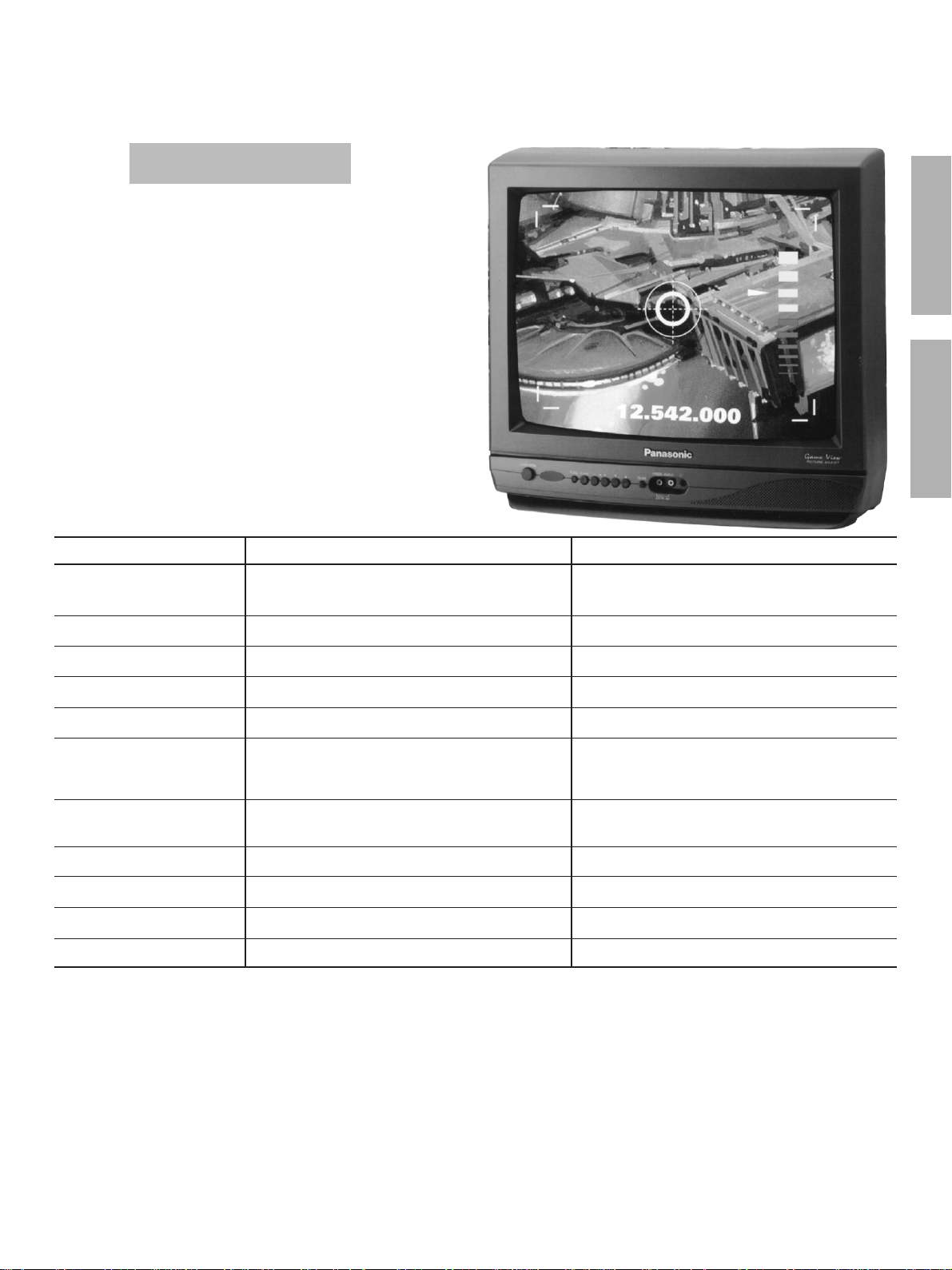
Color Television
TC-14B10P
TC-20B10P
Chassis MX5Y
Specifications
TV MODEL
Power Source
Power consumption, Max (A)
Antenna Input
Colour System
Tuning System
110/220 V AC, 50/60 Hz
75Ω - VHF/UHF/CATV
NTSC/AUTO/PAL-M/PAL-N
TC-14B10P
automatic switch
80W
F.S.T
ENGLISHESPAÑOL
TC-20B10P
110/220 V AC, 50/60 Hz
automatic switch
90W
75Ω - VHF/UHF/CATV
NTSC/AUTO/PAL-M/PAL-N
F.S.T
Channels Receiving
Picture Tube
(Measured Diagonally)
Audio Output
AV Input
Dimensions (W x H x D)
Weight
Remote Control Transmiter:
Power Source 3V (2 R6 batteries)
Infrared Length 9500 A (Angstron)
Number of Buttons 27 buttons
Dimensions (W x H x D) (51 x 28 x 150) mm
Wight 55g
Design and specifications are subject to change without notice
2 to 13 (VHF)
14 to 69 (UHF)
1 to 125 (CATV)
3W max (RMS)
1 (front) - 1 (rear)
370 x 351 x 366 mm
®
Panasonic
34 cm
9,6 kg
2 to 13 (VHF)
14 to 69 (UHF)
1 to 125 (CATV)
48 cm
3W max (RMS)
1 (front) - 1 (rear)
502 x 455 x 471 mm
17 kg
Provided accessories
l
1 Remote Control Transmiter
l
1 Balum 300Ω / 75Ω (Balum)
l
2 R6 size batteries 1,5V (ABNT/IEC)
l
1 Internal antenna (only for 14 models)
Page 2
Important Safety Notice
Special components are used in this television set which are important for safety. These parts are identified on the schematic
diagram by the symbol . It is essential that these critical parts are replaced whit the manufacturers specified replacement
parts to prevent X-ray radiation, shock, fire or other hazards. Do not modify the original design whitout manufacturers permission.
TABLE OF CONTENTS
OPERATION GUIDE ............................................................................. 03
SERVICE ADJUSTMENTS AND CALIBRATIONS
HOW TO OPERATE THE DAC CONTROLS ..................................... 06
HOW TO ENTER THE SERVICEMAN MODE ..................................... 06
HOW TO EXIT THE SERVICEMAN MODE ......................................... 06
DAC DIRECT TABLE ............................................................................ 07
MEMORY - DIRECT ACCESS METHOD ............................................. 07
EEPROM - MEMORY MAP .................................................................. 07
ELECTRICAL INSPECTION .................................................................. 07
INSPECTION OF THE DEFLECTION CIRCUITS ................................ 07
CUT OFF - PRE ADJUSTMENTS ........................................................ 08
CALIBRATION OF VIDEO IF ................................................................ 08
AFT ADJUSTMENTS ............................................................................. 09
AGC-RF ADJUSTMENTS ...................................................................... 09
NOISE LEVEL ADJUSTMENTS ............................................................ 09
VIDEO OUT ADJUSTMENTS ............................................................... 10
SUB-CONTRAST ADJUSTMENTS ....................................................... 10
COLOUR SATURATION ADJUSTMENTS .......................................... 10
SHARPNESS ADJUSTMENTS ............................................................. 10
SHUT DOWN SYSTEM COFIRMATION .............................................. 10
HORIZONTAL WIDTH AND CENTERING ADJUSTMENTS .............. 11
VERTICAL HEIGHT AND CENTERING ADJUSTMENTS ................... 11
WHITE BALANCE PRE ADJUSTMENTS ........................................... 11
CRT CUT OFF ADJUSTMENTS ........................................................... 11
FOCUS ADJUSTMENTS ..................................................................... 12
FRONT PANEL CHECKING ................................................................. 12
AV IN TERMINALS CHECKING ........................................................... 12
AUTOMATIC AND MANUAL MEMORIZATION .................................... 13
TUNE CHECKING ................................................................................. 13
AUDIO CHECKING ................................................................................ 13
PURITY AND CONVERGENCE ADJUSTMENTS .............................. 14
SCHEMATICS DIAGRAMS ................................................................... 15
IC601 BLOCK DIAGRAM / PINS AND FUNCTIONS ........................... 16
WAVE FORMS ...................................................................................... 17
CABINET PARTS LOCATION ............................................................... 19
CABINET REPLACEMENT PARTS LIST ............................................. 20
ELECTRICAL REPLACEMENT PARTS LIST ...................................... 21
General Guidelines
An Isolation Transformer should always be used during the servicing of a
receiver whose chassis is not isolated from the AC power line. Use a
transformer of adequate power rating as this protects the technician from
accidents resulting in personal injury from electrical shocks. It will also
protect the Receiver from being damaged by accidental shorting that may
occur during servicing.
When servicing, observe the original lead dress, especially in the high
voltage circuit. Replace all damaged parts (also parts that show signs of
overheating.)
Always Replace Protective Devices, such as fishpaper, isolation resistors
and capacitors, and shields after servicing the Receiver. Use only
manufacturers recommended rating for fuses, circuit breakers, etc.
High potentials are present when this Receiver is operating. Operation of
the Receiver without the rear cover introduces danger from electrical
shock. Servicing should not be performed by anyone who is not thoroughly
familiar with the necessary precautions when servicing high-voltage
equipment.
Extreme care should be practiced when Handling the Picture Tube. Rough
handling may cause it to implode due to atmospheric pressure (14.7 lbs
per sq. in). Do not sick or scratch the glass or subject it to any undue
pressure. When handling, use safety goggles and heavy gloves for
protection. Discharge the picture tube by shorting the anode to chassis
ground (not to the cabinet or to other mounting hardware). When
discharging, connect cold ground (i.e. dag ground lead) to the anode
with a well insulated wire or use a grounding probe.
Avoid prolonged exposure at close range to unshielded areas of the picture
tube to prevent exposure to X-ray radiation.
The Test Picture Tube used for servicing the chassis at the bench should
incorporate safety glass and magnetic shielding. The safety glass provides
shieldinf for the tube viewing area against X-ray radiation as well as
implosion. The magnetic shield limits X-ray radiation around the bell of
the picture tube in addition to restricting magnetic effects. When using a
picture tube test jig for service, ensure that the jig is capable of handling
31kV without causing X-ray radiation.
Before returning a serviced receiver to the owner, the service technician
must thoroughly test the unit to ensure that is completely safe to operatore.
Do not use a line isolation transformer when testing.
Warning !
It is essential that these critical parts are replaced
with the manufacturers specified replacement parts
to prevent X-ray radiation, shock, fire or other
hazards.
WARNING !!
Esquema Elétrico do chassi MX5Y ................. (em anexo)
Conserve-o sempre junto deste manual.
- 2 -
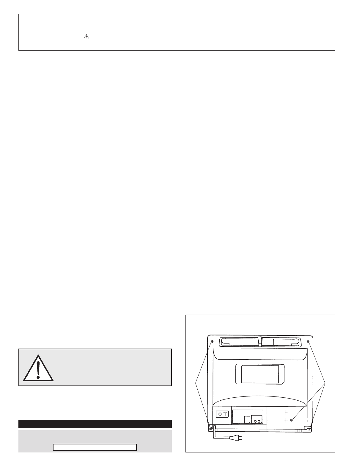
HOW TO OPEN THE CABINET
Screw
Screw
Page 3
Operation Guide TC-14B10P / TC-20B10P
ENGLISH
- 3 -
Page 4
Operation Guide TC-14B10P / TC-20B10P
- 4 -
Page 5
Operation Guide TC-14B10P / TC-20B10P
ENGLISH
- 5 -
Page 6
TC-14B10P / TC-20B10PService Adjustments and Calibrations
HOW TO OPERATE THE DAC CONTROL MX5Y
FUNCTIONS ADJUSTMENTS
1- SERVICEMAN MODE
1.1- TO ENTER CHQ MODE (SERVICE):
Set the OFF TIMER to 30 using the remote control
and adjust minimum volume at the TV panel. Press
simultaneously RECALL at the remote control and
VOL(-) at the tv panel. The white screen will appear
on receiver. Press RECALL again and the letters
CHQ will appear magenta with a blue background.
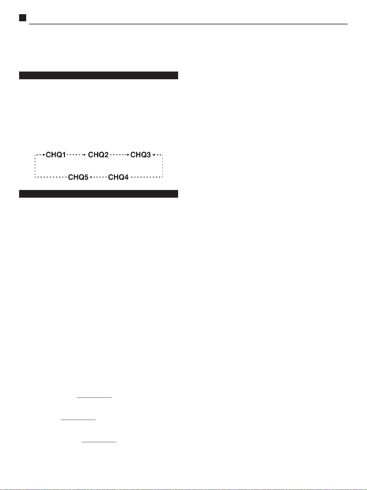
1.2- To alternate between CHQ modes, press 1 or 2
at the remote control (CHQ1 to CHQ5)
1.3- TO EXIT CHQ MODE (SERVICE):
Press N at the remote control, or just turn off the TV
using the remote control.
CHQ1
1.1- Press3or 4 to alternate the existing options: from
OP1 to OP6.
1.2- To change the data inside each sub-item press
VOL(+) or VOL(_) (the letter will be red). To memorize
the modifications press 0 (the letter will come back
to green).
OP1 (Colour system)
This option alternates between colour systems that will be
available within the TV set.
OP1=0 auto/PAL-M/NTSC (mod. Binorma)
OP2=1 auto/PAL-M/PAL-N/NTSC (mod. Trinorma)
OP1=2 Pal-M (mod.Pal-M)
OP2 (Game Function)
This option may turn the function GAME on/off.
OP3 (PANASONIC DEMO)
This option may turn the function DEMO on/off.
OP4 (TELE-TEXT) - not available
This option may turn the function TELE-TEXT on/off.
CHQ2
1.1- Press 3 or 4 to alternate between existing positions
like the sequence below:
To change between the data of each sub-item press
VOL(+) or VOL(_), the letter will stay green. No need
to memorize.
COLOUR ..........................USER
SUB-COLOUR .................CALIBRATION
TINT .................................USER
SUB-TINT ........................CALIBRATION
BRIGHT ........................... USER
SUB-BRIGHT .................. CALIBRATION
CONTRAST ..................... USER
SUB-CONTRAST ............ CALIBRATION
PURITY ............................USER
SUB-PURITY ...................CALIBRATION
CHQ3
1.1- Press 3 or 4 to alternate between the existing
options, as sequence below:
To change between the data in each sub-item press
VOL(+) or VOL(_), the letter will stay green. No need
to memorize.
HC ....................... HORIZONTAL CENTERING
VC ....................... VERTICAL CENTERING
V ALT .................. VERTICAL HEIGHT
CHQ4
1.1- Press 3 or 4 to alternate between the existing
options, as sequence below:
To change between the data in each sub-item press
VOL(+) or VOL(_), the letter will stay green. No need
to memorize.
AFT ..................... AFT CALIBRATION
VID................ VIDEO LEVEL CALIBRATION
RF..............AGC-RF CALIBRATION
CHQ5
1.1- Press 3or 4 to alternate between the existing
options, as sequence below:
To change between the data in each sub-item press
VOL(+) or VOL(_), the letter will stay green. No need
to memorize.
CHQ5 Options:
OP5 (SASO) - not available
This option may turn the function SASO on/off.
OP6 (NOISE MUTE) - not available
This operation may turn the function NOISE MUTE on/off.
Without the blue screen, it cuts off the noise when you are
working on a channel without reception or very weak signal.
B-CUT...........BLUE LOW LIGHT CALIBRATION
G-CUT.......... GREEN LOW LIGHT CALIBRATION
R-CUT...........RED LOW LIGHT CALIBRATION
B-DR......... BLUE HIGHT LIGHT CALIBRATION
R-DR......... RED HIGH LIGHT CALIBRATION
SUB-BR........ SUB BRIGHT CALIBRATION
BRIGHT........ BRIGHT CALIBRATION
- 6 -
Page 7
TC-14B10P / TC-20B10PService Adjustments and Calibrations
1.2- Press 5 at the remote control to make appear a white
line for screen calibration. In order to make tHe line
disappear press 5 again.
DAC DIRECT TABLE
CHQ1 CHQ2 CHQ3 CHQ4 CHQ5
OP1 SUB-COR HC AFT B-CUT
OP2 COR VC VID G-CUT
OP3 SUB-NITIDEZ V ALT RF R-CUT
OP4 NITIDEZ --- B-DR
OP5 SUB-CONTRAST R-DR
OP6 CONTRAST SUB BR
--- SUB-BRIGHT BRIGHT
--- BRIGHT ---
--- SUB-MATIZ ---
--- MATIZ ---
---
---
---
---
---
---
---
---
---
---
---
---
---
MEMORY - DIRECT ACCESS METHOD
1.1- To obtain direct access to memory go to item CHQ1,
press simultaneously VOL(_) at the TV set and mute
at the remote control.
1.2- To alternate between memory positions press 3or 4.
1.3- To change the contents of each memory positions
press VOL(+) or VOL(_), the letter will remain red. To
memorize the changes press 0, the letter will go
back to white.
1.4- To exit memory press 1 or 2 to alternate between
the CHQs or press N to exit SERVICE MODE .
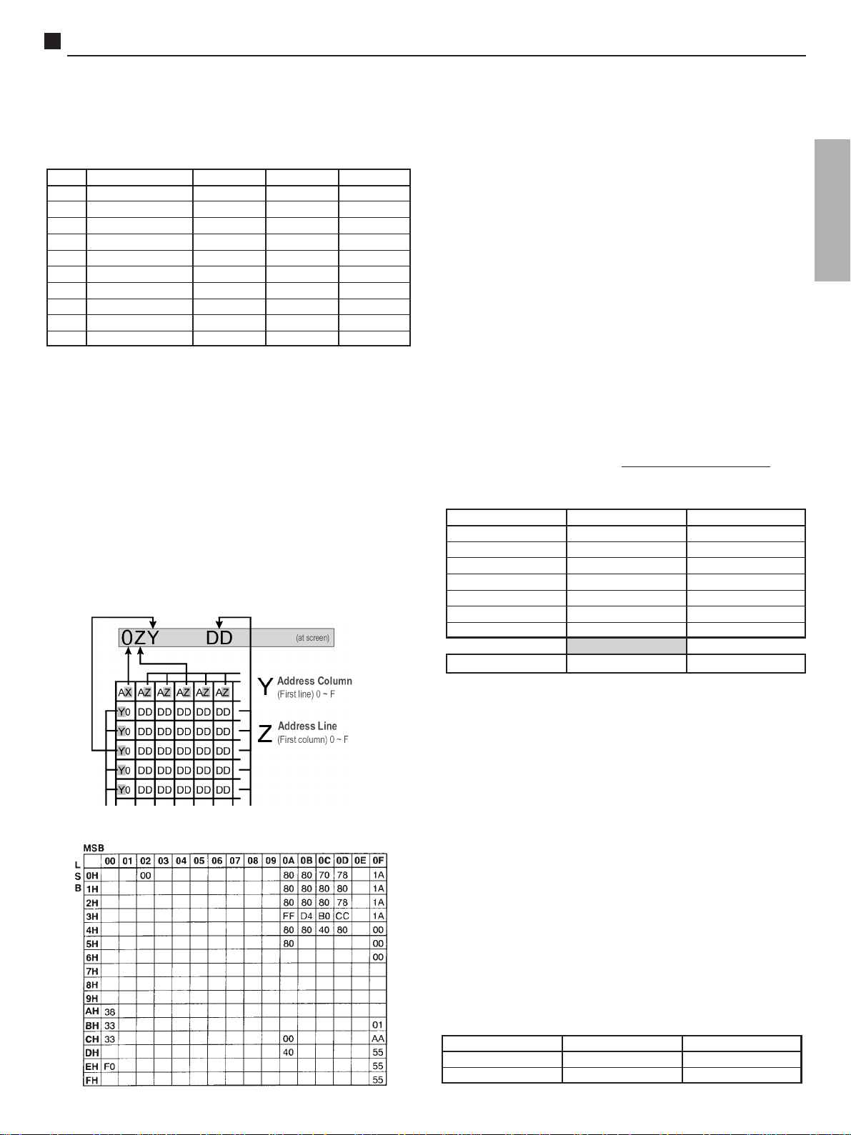
DATA MEMORY ON THE SCREEN
ELECTRICAL INSPECTION
1- EQUIPMENTS REQUIRED
1.1- High voltage meter, range to 30kv (eletrostatic or
resistive)
1.2- Voltmeter, range 30VDC, 150 VDC and 300VAC
1.3- Voltmeter RMS
1.4- DY,CY,CRT
2- PREPARATION
2.1- Position controls on the following positions:
NORMAL IMAGE....ADJUSTED
VOLUME.......... MINIMUM
TV/VIDEO............ TV
POT SCREEN................CENTER
POT FOCUS...........BEST POINT ( VISUAL)
3- VOLTAGE INSPECTION
3.1- Adjust AC input voltage to 110V.
3.2- Turn on the S801 switch.
3.3- Apply a CROSS HATCH pattern.
3.4- Adjust controls SUB BRIGHT ( SUB BR) in CHQ5
and SCREEN to obtain corrente de feixe zero.
3.5- Verify the voltage on the points below:
VOLTAGE
90V ± 2,0V
190V ± 15V E33 - PIN 1 300V
22V ± 2,0V D850 (K) 30V
44V ± 2,5V D852 (K) 50V
9V ± 1V TPE9 30V
5V ± 1V TPE10 30V
6,3 V
± 0,24V
RMS
180V ± 15V E33 - PINO 1 300V
TEST POINT METER
C823 (+) 300V
Y33 - PIN 4
For 14 models only
30V
RMS
ENGLISH
EEPROM MEMORY MAP
3.6- Position SCREEN and SUB BRIGHT ( SUB BR) to a
level where image is visible.
INSPECTION OF THE DEFLECTION
CIRCUITS AND PRE-ADJUSTMENTS
1- REQUIRED EQUIPMENTS.
1.1- High voltage meter, range up to 30Kv (eletrostatic or
resitor).
2- PROCEDURES.
2.1- Apply a PHILIPS pattern.
2.2- Select VERTICAL HEIGHT (V ALT) in CHQ3.
2.3- Adjust the heigth to obtain a correct image.
2.4- Apply a CROSS HATCH pattern.
2.5- Adjust BRIGHT, SUB BR, in CHQ5, SCREEN
minimum to obtain current=0
2.6- Measure high voltage with the voltmeter and verify if
is within the limits below:
METER
ELETROSTÁTICO
RESISTIVO
- 7 -
20 INCHES 14 INCHES
26,5 + 1,0 _ 1,5KV 24,5 + 1,0 _ 1,5KV
26,0 + 1,0 _ 1,5KV 24,0 + 1,0 _ 1,5KV
Page 8
TC-14B10P / TC-20B10PService Adjustments and Calibrations
2.7- Apply a PHILIPS pattern.
2.8- Adjust BRIGHT, SUB BR, in CHQ5, SCREEN to
obtain normal image.
2.9- Check if horizontal width is normal
2.10- Select SUB BR in CHQ5 and check if BRIGHT is
controlled by varying SUB BR in CHQ5.
2.11- Select HORIZONTAL CENTERING (HC) in CHQ3
(Service Mode) and adjust convergence.
2.12- Select VERTICAL CENTERING (VC) in CHQ3
(Service Mode) and adjust convergence.
3- PRÉ AJUSTE DO AGC RF.
3.1- Apply a PHILIPS pattern.
3.2- Adjust the signal level to 65±2bB (75Ω open).
3.3- Select RF AGC in CHQ4 Service Mode and increase
it pressing VOL(+). Verify if snow appear when the
RF AGC register is increased. Then decrease it slowly
by using VOL(_) until the snow has disappeared.
CUT OFF - PRE ADJUSTMENTS
1- REQUIRED EQUIPMENTS.
1.1- Oscilloscope.
1.2- Connect oscilloscope between TPY1 (Q352-C) and
ground.
1.3- Position controls/adjust following the information
below:
R HIGH LIGHT (R-DR)..................40H
B HIGH LIGHT (B-DR)...................40H
R LOW LIGHT (R-CUT).................000H
B LOW LIGHT (B-CUT).................000H
G LOW LIGHT (G-CUT)................ 125H
COR...............................................MINIMUM
CONTRASTE................................ MAXIMUM
SCREEN........................................MINIMUM
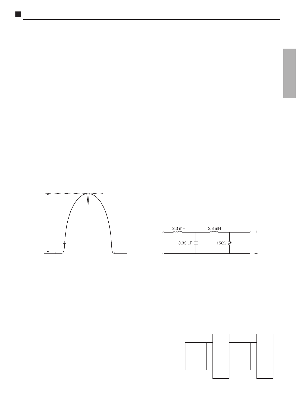
1.4- Apply a PHILIPS pattern.
1.5- Press 5 at the remote control to obtain a simple
horizontal line
1.6- Adjust G-CUT to obtain a reading at TPY1, as figure
below.(*)
1- SOUND INSPECTION
1.1- Verify if sound varies correctly pressing VOL(+) or
VOL(_).
1.2- Verify if tone is adjusted using the TONEcontrol at
the SOUND Menu.
2- INSPECTION OF COLOUR CONTROL
2.1- Apply a PHILIPS pattern.
2.2- Select Pic. Menu DYNAMIC, and adjust NORMAL
IMAGE using the remote control.
2.3- To access the function NORMAL IMAGE press MAIN
MENU and next press the < or > navigation keys to
select the function IMAGE.
Press the navigation keys to enter menu. Press the
N key at the remote control to activate function
NORMAL IMAGE.
2.4- Verify if saturation is normal and sufficcient.
2.5- Confirm the variation of the colour phase acting at the
TINT control, receiving NTSC pattern.
3- OTHER INSPECTIONS.
3.1- Tune the VHF, UHF and CATV channels and check if
there is good reception.
3.2- Press the key TV/VIDEO and verify ON SCREEN.
3.3- Return to the TV Mode.
<
CALIBRATION OF VIDEO IF
1- REQUIRED EQUIPMENT
1.1- Monitor
1.2- VIF generator
1.3- VIF detector
1.4- Power source of 9,0 ±0,1V and 4,0 ±0,1V
1.5- Bias box to AGC
1.6- Resistor Jumper of 1KΩ
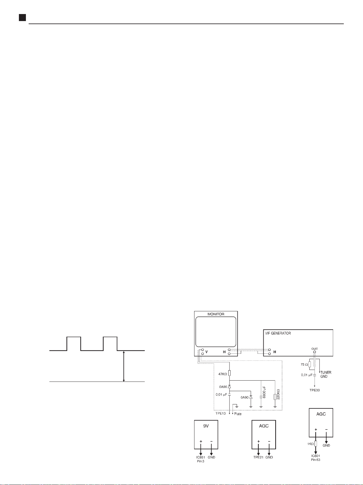
CONEXIONS
(*) 20 inch 160 ± 2Vo-p
(*) 14 inch 140 ± 2Vo-p
0V
1.7- Adjust SCREEN until a first line appears at the screen,
and dont change it after this.
1.8- Adjust the other DACs that match the other two
colours (R-CUT, B-CUT) until it turns the line white.
1.9- Exit to Normal Mode pressing NORMAL at the remote
control.
- 8 -
Page 9
TC-14B10P / TC-20B10PService Adjustments and Calibrations
CALIBRATION OF VIDEO IF ( continuing)
1- PREPARATION
2.1- Connect the VIF generator positive output cable to
TPE33 and the negative to ground.
2.2- Connect the VIF detector positive output cable to TPE13
and negative to ground.
2.3- Connect the +9V power source positive to pin 3 of IC851
and negative to ground.
2.4- Connect the +4V power source positive in series with
1KΩ resistor to pin 63 of IC601 and negative to ground.
2.5- Connect the polarization of AGC with positive to TPE21
(IF AGC) and negative to the ground.
2.6- Enter Serviceman Mode.
2- ADJUSTMENTS
3.1- Calibrate monitor to 200mVp-p
3.2- Decrease the VIF generator output to minimum signal.
3.3- First, turn on the instruments and after that, the power
sources.
3.4- Adjust bias AGC to obtain maximum gain.
3.5- Adjust the VIF generator output to obtain 200mVp-p at
the monitor.
3.6- Increase 20dB to VIF generator output and adjust the
Bias AGC to obtain 200mVp-p at the monitor
3.7- Confirm that the level of CC (42,17 MHz) and PC (
45,75 MHz) are within the especificated below.
ZERO BEAT
↓
42,75
200m Vp-p
CC 42,17
45 ± 15%
45,00
PC 45,75
45 ± 15%
3- ADJUSTMENTS
3.1- Adjust AFT using coil L167 until the voltage below
(*) is obtained at TPE29.
(*) 4,0±1,0V (after 10 seconds ON)
(*) 4.5±1,0V (after heating)
3.2- Vary the frequency of CW oscillator between
±100KHz and verify if tension variation at the
multimeter is higher than ±1,2V
AGC-RF ADJUSTMENTS
ENGLISH
1- REQUIRED EQUIPMENT
1.1- Digital Multimeter
1.2- Attenuator
2- PREPARATION
2.1- Tune a COLORBAR patten.
2.2- Adjust the input signal level to 64±2dB ( 75Ω open).
2.3- Connect Digital multimeter between TPE23 and
ground
3- ADJUSTMENTS
3.1- Select DAC AGC RF(RF) CHQ4 (Service Mode)
3.2- Adjust the DAC using the keys VOL(+) and VOL(_)
until ±6,2V at TPE23.
NOISE LEVEL ADJUSTMENTS
1- REQUIRED EQUIPMENTS
1.1- Oscilloscope
1.2- 7KHz filter
41,65
39,75
41,25
47,25
AFT ADJUSTMENTS
1- REQUIRED EQUIPMENTS
1.1- Oscilator CW 45,75 MHz
1.2- VIF detector
1.3- Digital multimeter
1.4- Short Jumper
2- PREPARATION
2.1- Disconnect the signal from the antenna terminal
2.2- Connect the multimeter between TPE29 and ground
2.3- Connect the CW oscilator using VIF detector
between TPE33 and ground
2.4- Adjust the CW oscilator output to 90+-5dBu
(75Ω open).
2.5- Position the DAC AFT in 80H.
Oscilloscope
2- PREPARATION
2.1- Tune a COLORBAR patten (no sound modulation).
2.2- Position tone control to center
2.3- Position VOLUME control to maximum.
2.4- Connect Oscilloscope to speakers terminals.
3- VERIFICATION
3.1- The maximum amplitude of the noise signal should
be less than 1,5Vp-p.
3.2- When it is higher than 1,5Vp-p, activate 7KHz filter
at the speakers terminals and verify if noise level is
less than 0,5Vp-p.
1,5Vp-p
- 9 -
Page 10

TC-14B10P / TC-20B10PService Adjustments and Calibrations
VIDEO OUT ADJUSTMENT
1- REQUIRED EQUIPMENT
1.1- Oscilloscope
1.2- Attenuator
2- PREPARATION
2.1- Apply a COLORBAR patten.
2.2- Adjust the input signal level to 75dB (75Ω open).
2.3- Connect the test tip of oscilloscope to TPE11
3- ADJUSTMENTS
3.1- Select DAC VIDEO (VID) CHQ4 (Service Mode).
3.2- Adjust the video signal level to 1,0±0,05Vo-p using
the keys VOL(+) and VOL(_).
1,0Vo-p
SUB-CONTRAST ADJUSTMENTS
1- REQUIRED EQUIPMENT
1.1- Oscilloscope
1.2- Jumper
1.3- Attenuator
COLOUR-SATURATION ADJUSTMENT
1- REQUIRED EQUIPMENT
1.1- Oscilloscope
1.2- Jumper
2- PREPARATION
2.1- Tune a COLORBAR patten.
2.2- Adjust the input signal level to 75dB (75Ω Open).
2.3- Confirm that the Picture Menu is DYNAMIC
2.4- Confirm that channel colour is NORMAL
2.5- Confirm that temperature of colour is NORMAL
2.6- Connect oscilloscope between TPE27 and ground
2.7- Connect the jumper between TPE3 and ground
2.8- Position controls at the following positions:
G LOW LIGHT (G-CUT)25H
BRIGHT.......NORMAL OR CENTER
CONTRAST.... NORMAL OR MAX.
COLOUR NORMAL OR CENTER
3- ADJUSTMENTS
3.1- Select DAC SUB BRIGHT at CHQ2.
3.2- Adjust SUB BRIGHT to make the pedestal level
remain 2,2±0,1Vp-p and confirm that there is no
deformation of waveform.
3.3- Select DAC SUB-COLOUR at CHQ2.
3.4- Adjust SUB- COLOUR level to 2,5±0,1Vp-p at
TPE27, as shown on figure below:
2- PREPARATION
2.1- Tune a COLORBAR patten.
2.2- Adjust the input signal level to 75dB (75Ω open )
2.3- Connect the jumper between TPE3 and ground
2.4- Connect the oscilloscope between TPE27 and
ground.
2.5- Confirm if Picture Menu is DYNAMIC.
2.6- Position the controls at the following positions:
G LOW LIGHT (G-CUT)...125H
BRIGHT..CENTER
CONTRASTNORMAL OR MAX.
COLOUR.MINIMUM
3- CALIBRATION
3.1- Select DAC SUB BRIGHT (SUB BR) CHQ2.
3.2- Adjust SUB BR until you have a level of 2,2±0,1Vp-p
and confirm if there is no deformation of waveform.
3.3- Select DAC SUB-CONTRAST, CHQ2.
3.4- Adjust SUB-CONTRAST level to 2,9±0,1Vp-p at
TPE27, as figure below.
Ajusted by Sub-Contraste
← 2,9 ± 0,1 Vp-p
Pedestal level
Ajusted by Sub-Bright
GND
← 2,2 ± 0,1 Vp-p
Adjusted by Sub-Color
← 2,5±0,1 Vp-p
Pedestal level
Adjusted by Sub-Bright
GND
← 2,2±0,1 Vp-p
SHARPNESS ADJUSTMENT
1- PREPARATION
1.1- Select sharpness control using Menu IMAGE
1.2- Adjust the control SHARPNESS to center.
2- ADJUSTMENTS
2.1- Select DAC SUB-SHARPNESS at CHQ2.
2.2- Adjust SUB SHARPNESS to(*) using the remote
control.
(*)14=17H
(*)20=1BH
2.3- Press key N to exit SERVICE mode.
SHUT DOWN SYSTEM CONFIRMATION
1- REQUIRED EQUIPMENT
1.1- DC power source
1.2- Voltmeter
- 10 -
Page 11
TC-14B10P / TC-20B10PService Adjustments and Calibrations
2- PREPARATION
2.1- Apply a CROSS HATCH pattern.
2.2- Adjust the controls BRIGHT and CONTRAST until
current turns to zero.
3- CONFIRMATION
3.1- Connect the DC voltmeter to cathode of D591 and
confirm that voltage is lower than level(*)A.
3.2- Adjust the DC power source to level(*)B and confirm
that SHUTDOWN is not acting.
3.3- Adjust the DC power source to level(*)C and confirm
that SHUTDOWN is not acting.
LEVELS 14 (V) 20 (V)
(*)A
(*)B
(*)C
21,60 22,30
23,60 24,10
25,60 26,10
HORIZONTAL WIDTH AND CENTERING
ADJUSTMENTS
1- ADJUSTMENT OF HORIZONTAL CENTERING
1.1- Position the control BRIGHT to minimum.
1.2- Tune to PHILIPS standards.
1.3- Select the DAC of HORIZONTAL CENTERING
(HC) at CHQ3 Service Mode.
1.4- Adjust the HORIZONTAL CENTERING using the
keys VOL(+) OR VOL(-).
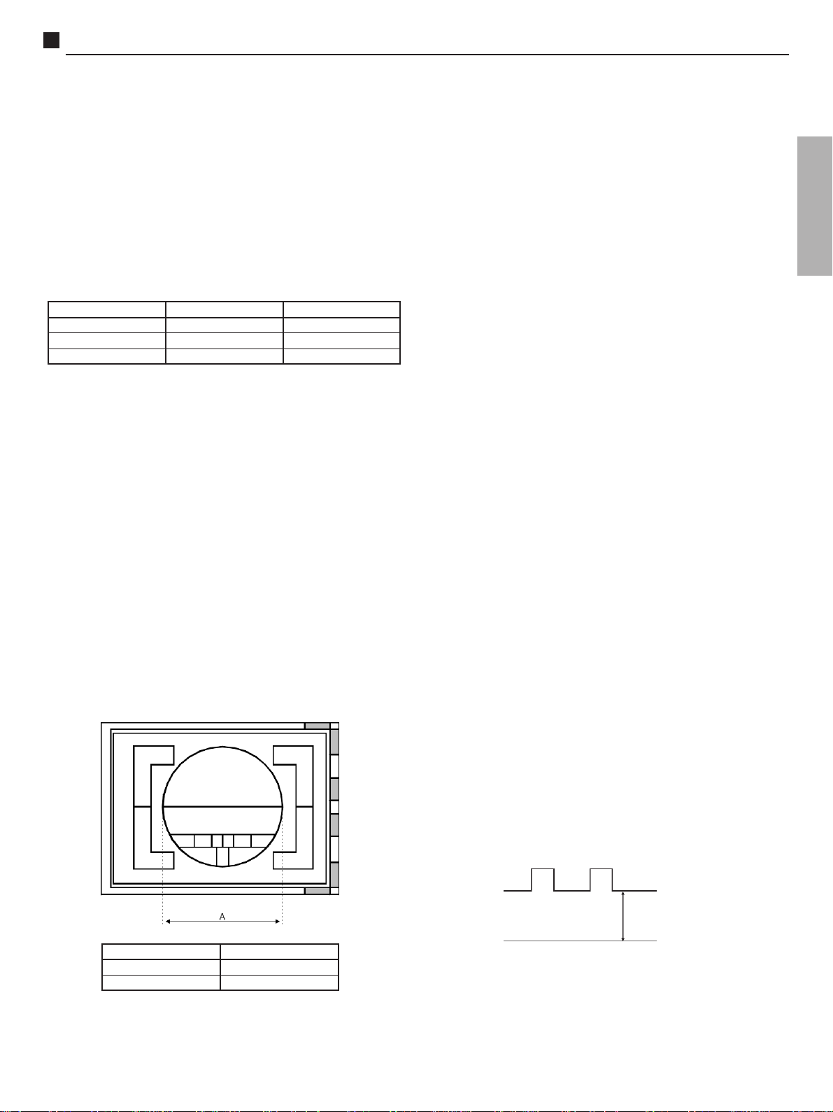
2- VERIFICATION OF HORIZONTAL WIDTH
2.1- Verify if horizontal width, is within the specifications
below:
VERTICAL HEIGHT AND CENTERING
ADJUSTMENTS
1- ADJUSTMENTS.
1.1- Tune a Philips pattern.
1.2- Select the DAC of VERTICAL CENTERING at
CHQ3 Service Mode.
1.3- Adjust the vertical placement pressing the VOL(+) or
VOL(_) keys until the image is centered.
Suggestion: the center line of CRT should coincide
with the centerline of PHILIPS pattern).
1.4- Select the DAC VERTICAL ALTITUDE (V ALT) AT
CHQ3 at SERVICE mode.
1.5- Adjust the correct altitude pressing VOL(+) or
VOL(_) keys
WHITE BALANCE PRE ADJUSTMENT AND
CRT CUT OFF ADJUSTMENT
IMPORTANT: This adjustment should be done after 15
minutes heating time.
1- REQUIRED INSTRUMENTS
1.1- Oscilloscope
2- PREPARATION.
2.1- Connect oscilloscope between TPY1 and ground.
2.2- Apply a PHILIPS pattern.
2.3- Confirm if Picture Menu is DYNAMIC
2.4- Confirm if Channel Color is NORMAL
2.5- Confirm Colour Temperature in NORMAL
2.6- Enter Service Mode at CHQ5.
2.7- Position controls at the following positions:
R HIGH LIGHT(R-DR).........40H
B HIGH LIGHT(B-DR)......... 4OH
R LOW LIGHT (R-CUT)..........000H
B LOW LIGHT(B-CUT)........000H
GLOW LIGHT(G-CUT)........125H
SCREEN........MINIMUM
ENGLISH
DIÂMETRO A MODELO
20 polegadas290 ± 5 mm
14 polegadas200 ± 5 mm
3- ADJUSTMENTS
3.1- Press 5 at the remote control to obtain a simple
horizontal line.
3.2- Confirm that the Pedestal level value at pin TPE27 is
2,2±0,1Vp-p.
3.3- Adjust G-CUT to obtain (*A) at TPY1, as figure
below:
(*A) 14 140±2Vp-p
(*A) 20 160±2Vp-p
0 V
3.4- Adjust SCREEN until a first line appears at the
screen, and dont change it after this.
3.5- Adjust the other DACs that correspond to the other
two colours (R-CUT,B-CUT) until line turns white.
3.6- Exit to normal mode pressing the key NORMAL at
the remote control.
- 11 -
Page 12

TC-14B10P / TC-20B10PService Adjustments and Calibrations
FOCUS ADJUSTMENT
1- PREPARATION
1.1- Apply a MONOSCOPE or PHILIPS pattern.
1.2- Confirm that Picture Menu is NORMAL DINAMIC
1.3- Adjust the controls to the following positions:
CONTRAST.....MAXIMUM
BRIGHT........... NORMAL
IMPORTANT:SUB BRIGHT adjustment should
have been done before.
2- ADJUSTMENTS
2.1- Adjust the FOCUS meter (FBT) until the best
focalization of image is obtained.
FRONT PANEL CHECKING
1- TV/AV VERIFICATION
1.1- Apply a PHILIPS pattern.
1.2- Press TV/AV button and verify if AV shows up ON
SCREEN
2- VOLUME VERIFICATION
2.1- Press VOL(+) or VOL(_) button and watch for a slight
variation.
2.2- Confirm that indication of volume position change
slightly on ON SCREEN.
3- CONFIRMING THE FUNCTION TURN ON/OFF OF
AC SWITCH
3.1- Turn OFF and turn ON the AC switch. Confirm that
previous memory position is saved. (it shows PHILIPS
pattern).
3.2- Confirm that volume is minimum and the other controls
are on the final adjustment condition.
3.3- Verify if led is on.
FINAL POSITION OF CONTROLS
VOLUME.........MINIMUM
COLOUR................CENTER
BRIGHT.......... CENTER
CONTRAST........MAXIMUM
6- VERIFICATION OF THE FUNC KEY
6.1- Press the FUNC key at the front panel and verify if
the following sequence appears:
AUTOMATIC TUNING
SKIPP CHANNEL OFF
ANTENNA TV
7- HOTEL MODE CONFIRMATION
7.1- Adjust the volume to 15.
7.2- Enter HOTEL MODE. To enter, set OFF TIMER to 30
and press simultaneously CH(+) at the front panel
and RECALL at the remote control.
7.3- Confirm that the MAIN MENU and OFF TIMER are
not operating.
7.4- Confirm that the maximum volume possible is 15
7.5- Exit HOTEL MODE. To exit, press simultaneously
VOL(_) at the front panel and OFF TIMER at the
remote control.
7.6- Confirm that OFF TIMER operates normally.
AV IN TERMINALS CHECKING
1- REQUIRED INSTRUMENTS
1.1- TV pattern signal generator
2- PREPARATION
2.1- The colour adjustment should already been done.
2.1- Set the TV/AV switch to AV position.
3- CONFIRMATION
3.1- Confirm that AV appears on ON SCREEN
3.2- Confirm that image and sound disappears
3.3- Connect the pattern signal generator to the rear AV
input terminal and confirm that noise and image
appears.
3.4- Connect the other source to the front AV input terminal
and confirm that the pattern signal connected to the
rear AV input terminal was substituted by the signal
of front AV input terminal.
3.5- Set the TV/AV switch to TV position.
4- CHECKING THE MICROPROCESSOR
4.1- Press the CH(+) or CH(_) button at the remote control
and confirm that ON SCREEN of the number of
channels previously tuned, up and down.
5- STAND BY OPERATION
5.1- Turn the TV on using the ON/OFF switch.
5.2- Press the ON/OFF button at the remote control to enter
in the STAND BY mode.
5.3- Disconnect and reconnect the power supply cable.
5.4- Confirm if TV set is at STAND BY.
5.5- Press the CH(+) or CH(_) button at the remote control
and verify if the TV turns on.
- 12 -
Page 13

TC-14B10P / TC-20B10PService Adjustments and Calibrations
AUTOMATIC AND MANUAL MEMORIZATION
1- VERIFICATION OF AUTOMATIC MEMORIZATION.
1.1- Adjust the input pattern signal level to 40 dB
1.2- Press FUNC at the front panel and it will appear an
indication of AUTOMATIC SINTONY.
Press VOL(+) at the front panel to begin automatic
memorization.
1.3- Verify the following items:
-Channel changes
-Automatic sintony
1.4- When memorization process is over, turn off the TV
using ON/OFF button.
1.5- Turn on the TV again using ON/OFF button and verify
the memorized channels using CH(+) or CH(_).
2- VERIFICATION OF MANUAL MEMORIZATION.
2.1- Press FUNC at front panel until select SKIP channel.
2.2- To add a channel press VOL(+) or VOL(_) until OFF
appears.
2.3- To take one channel out press VOL(+) or VOL(_) at
the set until ON appears.
2.4- To change channels press the CH(+) or CH(_).
AUDIO CHECKING
1- CONFIRMING TONE AND VOLUME
1.1- Apply a pattern signal with sound.
1.2- Confirm that high frequency sound is altered when tone
level is varied at Sound menu.
1.3- Press the VOL(+) or VOL(_) at the remote control and
notice a slight variation.
2- CONFIRMATION OF NOISE MUTE AND
BLUE SCREEN
2.1- Apply a PHILIPS pattern.
2.2- Turn on BLUE-BACK at the FUNC MENU. Confirm if
audio output is normal.
2.3- Eliminate antenna signal or reduce the signal strenght.
Confirm if blue screen appears and audio is cut off.
2.4- Turn off BLUE-BACK at the FUNC MENU. Verify if
blue screen doesnt appear and if sound exist (noise)
2.5- Turn BLUE-BACK again at FUNC MENU.
TUNE CHECKING
1- PREPARATION
1.1- Turn on the TV set using On/OFF switch.
2- VERIFICATION
2.1- Turn on signal at the TV set.
2.2- Press any existing channel number using the remote
control and verify if channel is selected.
2.3- Verify at bands VHF LOW, VHF HIGH, UHF and
CATV.
- 13 -
Page 14

TC-14B10P / TC-20B10PService Adjustments and Calibrations
PURITY AND CONVERGENCE ADJUSTMENTS
Adjustment is necessary only if the CRT or the deflection yoke is
replaced or if the setting was disturbed.
1. When the Yoke or the CRT are substituted:
1.1- Position the deflexion yoke and the convergence ring at the
neck of the CRT.
1.2- Position the convergence ring as figure below:
6 pole rings
Purity Rings
Centered
Over G3/G4 Gap
4 pole rings
1.3- Turn on the TV set and tune on a red pattern
1.4- Position the deflection coil to obtain an uniform red at the
screen.
1.5- Enter service mode and press RECALL at the remote control
to begin purity adjustment mode.
1.6- Leave the set heating up for 30 seconds at white screen.
2. Primary adjustment of estatic convergence (centering)
4.3- Overcome the red and blue lines with green adjusting the
rings 5 and 6 (adjust center)
5- DYNAMIC CONVERGENCE ADJUSTMENT
5.1-Move the DY on a horizontal and vertical way simultaneously,
to obtain a perfect side colour overcome.
5.2-Adjust the DY position for the image to stay symmetrical in
relation to the geometry of the screen.
5.3-Position the rubber parts to keep the DY in place.
5.4-If necessary, use permalloy to correct convergence on the
corners.
Note:To position the rubber parts (skids) to the DY, keep an
angle of 120 degrees between each part as is shown
on figure below:
Skids
(rubber)
°°
120
°
°°
120
°°
°
°°
°°
120
°
°°
2.1- Connect a crosshatch generator to the set and tune in signal.
Observe misconvergece at center of the screen only.
2.2- Adjust the 4 pole magnet (center rings); separate tabs and
rotate to converge blue with red.
2.2- Adjust the 6 pole magnet (rear rings); separate tabs and
rotate to convergence blue and red (magenta) with green.
Note: Precise convergence at this point is not important.
3- Purity Adjustment
3.1- Position TV set with screen pointed to the east
3.2- Fully degauss the receiver by using an external degaussing coil.
3.3- Press the RECALL button on the Remote Control again
until the Purity Check (green screen) appears.
3.4- Move away the deflection coil and adjust rings 1 and 2 in a
way that the red portion stay exactly centered in equal
proportions to blue and green. (figure below):
Red
Blue
3.5- Slowly move the deflection coil forward until an uniform red
is obtained completing the whole screen.
3.6- Fix the deflection coil in place
3.7- Keep RECALL button pressed at the remote control and
verify the purity of colours green, blue and white. Recheck
for purity and readjust if necessary.
Green
5.5- If necessary use permalloy to correct convergence on the corners.
5.6-Put procedure 3.7 into action.
5.7-Exit Service Mode.
VERIFY PURITY ADJUSTMENT WITH THE HELP OF A
MICROSCOPE
1- Apply a white pattern.
2- Using a microscope, observe the pixel with a correct format,
adjust the purity rings.
3- Using a microscope, observe the pixel on the sides of the screen
and compare figure below. To obtain a pixel with a correct
format, adjust the deflector coil moving forward and back.
4- Adjustment of estatic convergence
4.1- Apply a crosshatch pattern.
4.2- Overcome the red line to blue adjusting the rings 3 and 4
(adjust center).
- 14 -
Page 15

Y Boad (CRT 14)
TC-14B10P / TC-20B10PSchematics Diagrams
ENGLISH
Y Boad (CRT 20)
Yoke Board
- 15 -
Page 16

TC-14B10P / TC-20B10PIC601 - Block Diagram
IC601 - Pins and Functions
PINO NOME TENSÃO DESCRIÇÃO PINO NOME TENSÃO DESCRIÇÃO
01 VIF GND 0V GND for VIF/SIF Block
02 AFT OUT DC 0.3 - 8,7V AFT OUT
03 SIF LIMITER IN DC 0.5 - 4.5V SIF det. IN
04 RF AGC OUT DC 0.3 - 8.7V RF AGC OUT
05 QIF OUT DC 3.2V QIF det. OUT
06 IF AGC filter DC 1.8 - 4.6V IF AGC filter pin
07 QIF IN DC 1.8 - 4.6V QIF sound carrier input pin
08 Spot Killer DC 7.5V Spot killer capacitor pin
09 VIF IN (1) DC 1.5V VIF det. input pin
10 VIF IN (2) DC 1.5V VIF det. input pin
11 VIF Vcc (5V) DC 5.0V 5V to VIF/SIF Block
12 FAST BLK DC 0.0V TV/Half Tone/EXT RGB SW control
13 SCL SCL pin for IIC BUS
14 SCP Sand castle pulse output pin
15 HOUT H pin pre-drive output
16 VSS OV Ground pin of CMOS
17 SDA SDA pin of IIC BUS
18 VDD DC 5.0V VDD decoupling pin
19 AFC1 FILTER AFC-1 filter pin of 32fH VCO
20 H OSC DC 2.45V Pino H OSC
21 MUTE FILTER DC 0.3 - 8.7V Mute Filter
22 R OUT R output
23 G OUT G output
24 B OUT B output
25 DEFLECTION GND 0V Deflection GND
26 V OUT Vertical output
29 V RAMP feedback V RAMP feedback
30 V RAMP C V RAMP capacitor
27 START UP 9V (VCC) Deflection 9V, IIC BUS and VDD control
28 B IN DC 2.5V
37 G IN DC 2.5V
39 R IN DC 2.5V
31 Video Chroma VCC 5V 5V blocos de vídeo e croma
32 AFC2 FILTER DC 4.5V AFC2 FILTER
33 CHROMA IN DC 3.5V CHROMA input
34 ID FILTER Identification filter
35 VIDEO IN DC 2.7V Video input
36 X-RAY IN DC 0V X-RAY in
38 BLACK HOLD DC 3.1V Black level hold pin for black strech function
40 CONTRAST Detection ACL filter
41 X-TAL 3.58 DC 3.3V Crystal NTSC
42 KILLER FILTER DC 3.7V Killer filter
43 EXT IN DC 1.95V External video input
44 CHROMA APC DC 3.0V typ CHROMA APC FILTER
45 TV IN DC 1.95V Video input
46 VIDEO/CHROMA GND 0V GND for Video and Chroma blocks
47 Y SW OUT Video tuner output TV/EXT
48 H-SYNC SEP IN H-SYNC SEP IN
49 V-SYNC SEP IN V-SYNC SEP IN
50 X-TAL PAL DC 3.3V Crystal PAL
51 VIDEO CLAMP DC 3V Video Clamp
52 SECAM REF SECAM REF
53 Hi Vcc (9V) 9.0V 9V for output (RGB, AF, AFT/RF AGC)
54 -(B-Y) IN DC 2.9V SECAM signal input
55 -(R-Y) IN DC 2.9V SECAM signal input
56 VIF APC FILTER2 DC 3.0V VIF APC filter
57 OUDIO OUT DC 2.8V Audio output
58 AUDIO BYPASS DC 2.3 ~ 3.0V Audio Bypass
59 EXT AUDIO IN DC 2.5V External Audio input
60 FM DIRECT OUT DC 2.5V Audio output
61 VIF VCO(1) DC 4.2V Coil VIF VCO
62 VIF VCO(2) DC 4.2V Coil VIF VCO
63 VIF APC FILTER1 DC 3.0V VIF APC filter
64 VIF VIDEO OUT 2.2Vp-p Video Detector output
- 16 -
Page 17

TC-14B10P / TC-20B10PWave Forms / Formas de Onda - (01 to 12)
HOW TO OBTAIN WAVE FORMS
1. The indication at the schematic diagram , shows the place of measuring points of the respective wave forms, shown below. The place is not
exact, another point, in the same connection, can be used to have a measurement.
2. Connect to the terminal of antenna (RF), one signal generator - colorbar PAL-M.
3. Adjust the controls of TV set (audio /picture) to normal. Adjust the volume to minimum.
4- Every form of video wave should be visualized in the oscilloscope of wide band and low capacity test points (1 to 10 ). The form and peak amplitude
may vary depending on the oscilloscope and its adjustment.
Q802 - Coletor (Stand-By)
Nº
Q801 - Emissor
01
04
Q801 - Emissor (Off)
Q802 - Base (On)
02
05
Q802 - Coletor (On)
Q804 - Base (Off)
03
06
ENGLISH
ESPAÑOL
Q804 - Base - (On)
IC401 - Pino 4
07
10
IC1101 - Pino 40
IC401 - Pino 2 IC401 - Pino 5
08
11
Q803 - Base (On)
09
12
- 17 -
Page 18

TC-14B10P / TC-20B10PWave Forms / Formas de Onda - (13 to 24)
Como obtener las formas de onda:
1. La indicación BLK , en el esquema electrico de la placa E/Y, muestra la localización del punto de medición de las respectivas formas de onda
mostradas abajo. La localización és genérica, podiendo ser utilizado otro ponto más accecible de la conexión para se efectuar la medición.
2. Conect al terminal de antena (RF), un generador de señal Colorbar PAL-M.
3. Ajuste los controles del televisor (audio/picture) para normal. Ajuste el volumen para mínimo.
4. Todas las formas de onda de video deben ser visualizadas en osciloscopio de banda ancha y con punta de puebra de baja capacitancia (1 a 10).
La forma y amplitud de pico pueden variar dependiendo del osciloscopio y de su ajuste.
Nº
IC401 - Pino 7
IC601 - Pino 20
13
16
IC601 - Pino 32
IC601 - Pino 33
14
17
IC601 - Pino 15
IC601 - Pino 44
15
18
IC601 - Pino 48
19
22
IC601 - Pino 62
IC601 - Pino 64
20
23
IC601 - Pino 49
Q549 - BaseIC601 - Pino 50
21
24
- 18 -
Page 19

Vista por Explosión
TC-14B10P / TC-20B10PCabinet Parts Location
ENGLISHESPAÑOL
- 19 -
Page 20

Lista de Piezas Mecánicas
TC-14B10P / TC-20B10PCabinet Replacement Parts List
REF.
NO.
01 AV TERMINAL (frontal) JK2
02 ASSY, E/Y BOARD
03 SWITCHES (S1101 A S1106)
04 FUSE HOLDER
05 FLAT CABLE 4 VIAS (E33-Y33)
06 FLAT CABLE 5 VIAS (E32-Y32)
07 BASE DE PINOS E22
08 TUNER
09 POWER SWITCH (S801)
10 TRANSFORMER CHOPER - T801A
11 TRANSFORMER FLYBACK - T501
12 AV TERMINAL (rear) JK2
13 CRT SOCKET
14 TRANSFORMER DRIVE (T550)
DESCRIPTION PART NO. TO TC-14B10P PART NO. TO TC-20B10P
TJB4G605
TZGNPEY14A10
BVQPB001T
EYF52BC
TXAJTE33CB14A9-1
TXAJTE32CB14A9
BJP11V02-AP
ENV56D75G3
ESB92DA1B
ETS29AK286AC
KFT2AB281F1
TJB16664
TJS1A5081
TLH15462M
TJB4G605
TZGNPEY20A10
BVQPB001T
EYF52BC
TXAJTE33CB14A9-1
TXAJTE32CB20A9
BJP11V02-AP
ENV56D75G3
ESB92DA1B
ETS29AK286NC
KFT3AB280F1
TJB16664
TJS1A5050
TLH15462M
15 AC CORD
16 AC CORD HOLDER
17 REMOTE CONTROL SENSOR
18 RC SENSOR BRACKET
19 FUSE (F801)
20 CRT
21 SPEAKER 3W 16
22 COIL, DEGAUSSING
23 CONECTOR (E22)
24 ASSY, DAG GROUND
25 POWER BUTTON
26 INFRA RED GUIDE
27 PANA BADGE
28 BUTTON, 6 KEY
29 RC SENSOR WINDOW
30 FRONT CABINET
ΩΩ
Ω
ΩΩ
TSX2B1421SB
TMM2B202-1
RPM6937-V13
TMW2B204
XBAV2C3R1TL-BS
A34EJL01X091R
EAS-9D104ZC
TLK2B14001A
TXAJTE22CB20A8-1
TXF3A14C7
TBX2B846-1
TKK2B0304
TBM153023
TBX2B845-1
TKP2B11131-1
TKY2B1101-2
TSX2B1421SB
TMM2B202-1
RPM6937-V13
TMW2B204
XBAV2C3R1TL-BS
A48EJN05X091R
EAS-9D104ZC
TLK2B20001A
TXAJTE22CB20A8-1
TXF3A20C7-1
TBX2B846-1
TKK2B0304
TBM4G3001
TBX2B845-1
TKP2B11131-1
TKY2B1001-3
31 BALUM 300/75
32 REMOTE CONTROL UNIT
33 BACK CABINET
34 ANTENNA UNIT
35 ASSY, FRONT CABINET
ΩΩ
Ω
ΩΩ
S-U5012
TNQ2B2703
TKU2B21503-1
TSA8108-6K
TXFKY14B10P
- 20 -
S-U5012
TNQ2B2703
TKU2B21403-1
-----O-----
TXFKY20B10P
Page 21

Replacement Parts List
Lista de Piezas
TC-14B10P
ASSEMBLED MAIN BOARD / PLACAS MONTADAS
REF. NO.
PART NO. DESCRIPTION REF. NO.
TZGNPEY14B10P PLACA EY MONTADA TC-14B10P
CAPACITORS / CONDENSADORES
C104 ECA1HM3R3B CAP, ELETROLIT 3,3 UF 50V
C111 ECA1CM100B CAP, ELETROLIT 10 UF 16V
C112 ECA1HM4R7B CAP, ELETROLIT 4,7 UF 50V
C128 ECUV1H103ZFX CAP, CER SMD 10 NF 50V
C150 ECUV1H103ZFX CAP, CER SMD 10 NF 50V
C151 ECA1HM010B CAP, ELETROLIT 1 UF 50V
C152 ECA1HMR22B CAP, ELETR. 0,22 UF 50V
C155 ECA1CM470B CAP, ELETROLIT 16V 47UF
C156 ECUV1H103ZFX CAP, CER SMD 10 NF 50V
C159 ECUV1H103ZFX CAP, CER SMD 10 NF 50V
C160 ECA1HM100B CAP, ELETROLIT 10 UF/ 50V
C161 ECUV1E104ZFX CAP, CERAMIC 100 NF 25 V
C163 ECUV1H104ZFX CAP, CERAMIC 100 NF 50V
C165 ECUV1H101JCX CAP, CERAMIC 100 PF 50V
C167 ECUV1H270JCX CAP, CERAMIC 27 PF 50V
C168 ECA1HMR33B CAP, ELETR. 0,33 UF 50V
C169 ECUV1H221JCX CAP, CERAMIC 220 PF 50V
C201 ECUV1H103KBG CAP, CERAMIC 10 NF 50 V
C202 ECA1HM3R3B CAP, ELETROLIT 3,3 UF 50V
C203 ECA1CM100B CAP, ELETROLIT 10 UF 16V
C204 ECUV1H272KBX CAP, CERAMIC 2700 PF 50V
C210 ECUV1H152KBX CAP, CERAMIC 1500 PF 50V
C211 ECEA1HN010SB CAP, ELETROLITICO BIPOL 1UF 50V
C240 ECUV1H560JCX CAP, CERAMIC 56 PF 50V
C350 ECCR1H331J5 CAP, CERAMIC 330PF; 50V
C351 ECCR1H391J5 CAP, CERAMIC 390PF,50V
C352 ECCR1H331J5 CAP, CERAMIC 330PF; 50V
C353 ECCR1H391J5 CAP, CERAMIC 390PF,50V
C354 ECKW3D821KBP CAP, CERAMIC
C356 ECKW2H103PU8 CAP, CERAMIC 10NF; 500V
C401 ECA1VM102B CAP, ELETR. 1000UF - 35V
C402 ECA1HM100B CAP, ELETROLIT 10 UF/ 50V
C403 ECA1EM332E CAP, ELETR. 3300 UF 25 V
C405 ECUV1H102KBX CAP, CERAMIC 1 NF 50V
C406 ECUV1H102KBX CAP, CERAMIC 1 NF 50V
C420 ECUV1E104KBX CAP, CERAMIC 100 NF 25 V
C425 ECA1HM010B CAP, ELETROLIT 1 UF 50V
C430 ECUV1H103KBX CAP, CERAMIC 10 NF 50V
C431 ECA1CM100B CAP, ELETROLIT 10 UF 16V
C451 ECQE1224KF3 CAP, POLIESTER
C452 ECA1VM101B: CAP, ELETROL 100 UF 35V
C453 ECQB1H333JM3 CAP, POLIESTER 33NF, 50V
C501 ECA1HM0R1B CAP, 0,1 UF 50V
C503 ECKR2H471KB5 CAP, CERAMIC 470PF;500V
C504 ECKR2H471KB5 CAP, CERAMIC 470PF;500V
C505 ECKR2H561KB5 CAP, CERAMIC 560PF,500V
C506 ECEA2EU100WB CAP, ELETROLIT 10UF 250V
C507 ECA1EM471B CAP, ELETROLIT 470 UF 25V
C508 ECA1VM332E CAP, ELETR. 3300 UF 35 V
C510 ECA1CM470B CAP, ELETROLIT 16V 47UF
C519 ECUV1H330JCX CAP, CERAMIC 33 PF 50V
C520 ECA1HM010B CAP, ELETROLIT 1 UF 50V
C521 ECUV1H103KBG CAP, CERAMIC 10 NF 50 V
C522 ECQB1H822JM3 CAP, DE POLIES 8,2 NF 50 V
C525 ECA1HM4R7B CAP, ELETROLIT 4,7 UF 50V
C526 ECUV1H103ZFX CAP, CER SMD 10 NF 50V
C530 ECUV1H122KBN CAP, CERAMIC 50V 1,2NF
C531 ECA1HM010B CAP, ELETROLIT 1 UF 50V
C543 ECA1CM221B CAP, ELETROLIT 220U 25V
C546 ECA1HM010B CAP, ELETROLIT 1 UF 50V
CAPACITORS / CONDENSADORES
PART NO. DESCRIPTION
C548 ECQB1H123JM3 CAP, DE POLIESTER 12 NF 50 VV
C551 ECKD3D221JBP CAP, CERAMIC 220 PF 2 K V
C552 ECWH12H123JS CAP, POLIPROP. 12 NF 1600V
C553 ECQM4153JZW CAP, POLIESTER15NF; 400V
C554 ECKW3D222JBP CAP, CERAMIC 2200PF 2KV
C555 ECQM4223JZW CAP, POLIESTER 22NF; 400V
C558 ECKW3D272JBP CAP, CERAMIC 2700PF 2KV
C559 TAC7A2D684JC CAP, POLIPROPILENO 680 NF 200V
C559 TACFV2E684J CAP, POLIPROPILENO 680 NF 200V
C580 ECA1CM330B CAP, ELETROLIT 33 UF 16V
C582 ECA1HM010B CAP, ELETROLIT 1 UF 50V
C585 ECUV1H101JCX CAP, CERAMIC 100 PF 50V
C590 ECA1VM101B: CAP, ELETROL 100 UF 35V
C591 ECKR2H331KB5 CAP, CERAMIC 330 PF; 500V
C601 ECA1HMR22B CAP, ELETR.0,22 UF 50V
C604 ECUV1H680JCX CAP, CERAMIC 68 PF 50V
C605 ECUV1H103ZFX CAP, CER SMD 10 NF 50V
C606 ECA1CM470B CAP, ELETROLIT 16V 47UF
C607 ECUV1H220JCX CAP, CERAMIC 22 PF 50V
C608 ECUV1H220JCX CAP, CERAMIC 22 PF 50V
C610 ECA1AHG471B CAP, ELETROLIT 470 UF 10 V
C611 ECUV1E104ZFX CAP, CERAMIC 100 NF 25 V
C612 ECUV1E104ZFX CAP, CERAMIC 100 NF 25 V
C613 ECUV1E104ZFX CAP, CERAMIC 100 NF 25 V
C615 ECA0JM101B CAP, ELETROLIT 100 UF 6,3V
C616 ECUV1H223ZFX CAP, CERAMIC 22 NF 50V
C620 ECUV1H223KBX CAP, CERAMIC 22 NF 50V
C621 ECUV1H223KBX CAP, CERAMIC 22 NF 50V
C622 ECUV1C224KBX CAP, CERAMIC 220 NF 16 V
C623 ECUV1H820JCX CAP, CERAMIC 82 PF 50V
C625 ECUV1H220JCX CAP, CERAMIC 22 PF 50V
C626 ECUV1E104KBX CAP, CERAMIC 100 NF 25 V
C627 ECA1HMR47B CAP, ELETROLIT 0,47 UF 50V
C628 ECUV1H153KBX CAP, CERAMIC 15 NF 50 V
C633 ECA1CM221B CAP, ELETROLIT 220U 25V
C634 ECUV1H103ZFX CAP, CER SMD 10 NF 50V
C801 ECQU2A104MN CAP, POLIESTER 100 NF 250 VAC
C810 EC0S2GP221CB CAP, ELETROLIT 220 UF 400V
C814 ECKW3D152JBP CAP, CERAMIC 1500 PF 2KV
C815 ECQV1H154JM3 CAP, DE POLIES 0.15 UF 50 V
C816 ECQB1H103JM3 CAP, POLIESTER 50V 10NF
C817 ECQB1H473JM3 CAP, POLIESTER 47NF 50VV
C818 ECA1CM101GB CAP, ELETROLIT 100 UF 16V
C820 ECQB1H223JM3 CAP, POLIESTER 22NF, 50VV
C821 ECQB1H273JM3 CAP, DE POLIES 27NF 50V
C822 ECKW3D222JBP CAP, CERAMIC 2200PF 2KV
C823 EC0S2CA221AB CAP, ELETROLIT 220UF 160V
C823 EC0S2CA221BB CAP, ELETROLIT 220UF 160V
C828 ECA1EM331B CAP, ELETROLIT 330UF 25V
C829 ECA1CM101GB CAP, ELETROLIT 100 UF 16V
C830 ECA0JM101B CAP, ELETROLIT 100 UF 6,3V
C840 ECKCNA222MEB CAP, CERAMIC 2200 PF 4000 V
C850 ECA1EHG102B CAP, ELETROLIT 1000 UF 25 V
C851 ECKR2H471KB5 CAP, CERAMIC 470PF;500V
C852 ECKR2H222KB5 CAP, CERAMIC 2,2 KPF 500V
C853 ECA1HHG221B CAP, ELETROLIT 220 UF 50V
C854 ECA1CM100B CAP, ELETROLIT 10 UF 16V
C858 ECQB1H473JM3 CAP, POLIESTER 47NF 50VV
C870 ECA1VM101B: CAP, ELETROL 100 UF 35V
C871 ECA0JM101B CAP, ELETROLIT 100 UF 6,3V
C1051 ECUV1H103ZFX CAP, CER SMD 10 NF 50V
C1052 ECA1CM470B CAP, ELETROLIT 16V 47UF
C1053 ECUV1H101JRX CAP, CERAMIC 100 PF 50 V
ENGLISHESPAÑOL
- 21 -
Page 22

Replacement Parts List
Lista de Piezas
TC-14B10P
CAPACITORS / CONDENSADORES
REF. NO.
C1101 ECUV1H471JCX CAP, CERAMIC 470 PF 50V
C1102 ECUV1H103ZFX CAP, CER SMD 10 NF 50V
C1103 ECUV1H563KBX CAP, CERAMIC 56 NF 50 V
C1120 ECA1CM100B CAP, ELETROLIT 10 UF 16V
C1125 ECA1HM2R2B CAP, ELETROLIT 2,2UF 50V
C1130 ECA1HM4R7B CAP, ELETROLIT 4,7 UF 50V
C1131 ECA1CM470B CAP, ELETROLIT 16V 47UF
C1135 ECUV1H103ZFX CAP, CER SMD 10 NF 50V
C1137 ECA1CM220B CAP, ELETROLIT 22 UF 16V
C1138 ECUV1H103ZFX CAP, CER SMD 10 NF 50V
C1145 ECUV1H681JCX CAP, CERAMIC 680 PF 50V
C1146 ECUV1H101JCX CAP, CERAMIC 100 PF 50V
C1149 ECUV1H560JCX CAP, CERAMIC 56 PF 50V
C1151 ECUV1H820JCX CAP, CERAMIC 82 PF 50V
C1152 ECUV1H820JCX CAP, CERAMIC 82 PF 50V
C1153 ECUV1H820JCX CAP, CERAMIC 82 PF 50V
C1160 ECA1CM471B CAP, ELETROLIT 16V 470UF
C1161 ECUV1H103ZFX CAP, CER SMD 10 NF 50V
C1170 ECUV1H101JCX CAP, CERAMIC 100 PF 50V
C1171 ECUV1H101JCX CAP, CERAMIC 100 PF 50V
C1172 ECUV1H103ZFX CAP, CER SMD 10 NF 50V
C1173 ECA1CM100B CAP, ELETROLIT 10 UF 16V
C2301 ECUV1H103KBX CAP, CERAMICO 10 NF 50V
C2302 ECA1CM100B CAP, ELETROLIT 10 UF 16V
C2305 ECA1CM100B CAP, ELETROLIT 10 UF 16V
C2306 ECA1CM470B CAP, ELETROLIT 16V 47UF
C2307 ECA1EM222E CAP, ELETROLITICO 2200 UF 25V
C2308 ECUV1H103ZFX CAP, CER SMD 10 NF 50V
C2309 ECA1EM471B CAP, ELETROLIT 470 UF 25V
C2310 ECQV1H224JM3 CAP, POLIESTER 220 NF 50V
C2311 ECQV1H224JM3 CAP, POLIESTER 220 NF 50V
C2312 ECA1VM470B CAP, ELETROLIT 47 UF 35 V
PART NO. DESCRIPTION REF. NO.
DIODES / DIODOS
D401 ERA1501V3 DIODE
D402 MA4360MTA DIODE, ZENER
D501 EU2V1 DIODE, RECTIFIER
D502 EU2V1 DIODE, RECTIFIER
D503 EU2V1 DIODE, RECTIFIER
D504 MTZJT-7736A DIODE, ZENER
D510 EU2V1 DIODE, RECTIFIER
D512 MTZJT-775.6A DIODE, ZENER
D545 MA171TA5 DIODE
D551 ERB06-15V1 DIODE
D552 RU2AMV1 DIODE
D580 D1NL20UV70 DIODE, RECTIFIER
D590 MA4108JTA DIODE
D591 MA171TA5 DIODE
D801 TAP2B0001 POSISTOR, 3 PINS 7 OHMS
D802 D4SB80 DIODE RECTIFIER
D803 MTZJT-7712C DIODE, ZENER 12V 0,5W
D804 D1NL20UV70 DIODE, RECTIFIER
D805 MTZJT-7715C DIODE, ZENER 15 V 0,5 W
D806 MTZJT-775.1C DIODE, ZENER 5.1 V
D815 D1NL20UV70 DIODE, RECTIFIER
D816 D1NL20UV70 DIODE, RECTIFIER
D817 S2L60V61 DIODE
D820 SR2KSV1 DIODE
D821 0N3131LF DIODE, PHOTO COUPLER
D840 PC123F2 DIODE, PHOTO COUPLER
D850 D1NL20UV70 DIODE, RECTIFIER
D851 MTZJT-772.4B DIODE, ZENER
D852 EU02V1 DIODE
DIODES / DIODOS
PART NO. DESCRIPTION
D853 MTZJT-778.2C DIODE, ZENER 8,2 V
D854 MA27T-ATA DIODE, SIGNAL
D870 D1NL20UV70 DIODE, RECTIFIER
D1120 1SS254T77 DIODE, SIGNAL
D1145 1SS254T77 DIODE, SIGNAL
D1170 MTZJT-776.8C DIODE, ZENER 6,8 V
D1171 MTZJT-776.8C DIODE, ZENER 6,8 V
INTEGRATED CIRCUITS / CIRCUITOS INTEGRADOS
IC401 LA7840 IC VERTICAL-OUT
IC601 M52770ASP700 IC
IC801 SE090NLF4 IC REGULATOR 90V
IC850 AN78M05LB IC REGULATOR 5V
IC851 AN78M09LB IC REGULATOR 9V
IC852 AN78M05LB IC REGULATOR 5V
IC1052 RPM637CBRS2 IC
IC1052 RPM6937-V13 IC
IC1101 MN1871681TE IC
IC1102 S-24C02ADP IC EEPROM 2K
IC1103 S-80741AL-Z IC RESET
IC2301 LA4289N IC AUDIO OUTPUT
JUMPERS
JA6 ERJ6GEY0R00V RES, METAL 1/10W 0 OHM
JA11 ERJ6GEY0R00V RES, METAL 1/10W 0 OHM
JA12 ERJ6GEY0R00V RES, METAL 1/10W 0 OHM
JA13 ERJ6GEY0R00V RES, METAL 1/10W 0 OHM
JA14 ERJ6GEY0R00V RES, METAL 1/10W 0 OHM
JA16 ERJ6GEY0R00V RES, METAL 1/10W 0 OHM
JA17 ERJ6GEY0R00V RES, METAL 1/10W 0 OHM
JA21 ERJ6GEY0R00V RES, METAL 1/10W 0 OHM
JA30 ERJ6GEY0R00V RES, METAL 1/10W 0 OHM
JS1052 ERJ6GEY0R00V RES, METAL 1/10W 0 OHM
JS1054 ERJ6GEY0R00V RES, METAL 1/10W 0 OHM
JS1120 ERJ6GEY0R00V RES, METAL 1/10W 0 OHM
COILS / BOBINAS
L140 TLX180KD01 COIL, PEAKING 18 UH
L141 TLUABTA101K COIL, DE PICO 100 UH
L142 TLUABTA470K COIL, PEAKING 47 UH
L150 TLX101KD01 COIL, PEAKING 100 UH
L167 EIV7EN053B BOBINA VARIAVEL
L240 TLX100KD01 COIL, PEAKING 10 UH
L402 EXCELSA35T FERRITE
L501 EXCELSA35T FERRITE
L551 EXCELSA35B FERRITE
L552 EXCELSA24T FERRITE
L555 EXCELSA39V FERRITE
L556 EXCELSA35T FERRITE
L580 EXCELSA39V FERRITE
L611 EXCELSR35T FERRITE
L612 EXCELSR35T FERRITE
L620 EXCELSA39V FERRITE
L623 TLX100KD01 COIL, PEAKING 10 UH
L801 ELF18D290TZ LINE FILTER
L810 EXCELSA24T FERRITE
L850 EXCELSA35T FERRITE
L1152 EXCELDR25V FERRITE
- 22 -
Page 23

Replacement Parts List
Lista de Piezas
TC-14B10P
TRANSISTORS / TRANSISTORES
REF. NO.
Q140 2SD601ATX TRANSISTOR SMD
Q160 2SB709ATX TRANSISTOR SMD
Q161 2SB709ATX TRANSISTOR SMD
Q351 2SC1573AH TRANSISTOR
Q352 2SC1573AH TRANSISTOR
Q353 2SC1573AH TRANSISTOR
Q548 2SD601ATX TRANSISTOR SMD
Q549 2SD1275ARL TRANSISTOR
Q551 2SD2499LBMAM TRANSISTOR SAÍDA HORIZONTAL
Q580 2SB709ATX TRANSISTOR SMD
Q601 2SD601ATX TRANSISTOR SMD
Q602 2SD601ATX TRANSISTOR SMD
Q801 2SC5241 TRANSISTOR
Q802 2SD789ETZ TRANSISTOR
Q803 2SD789ETZ TRANSISTOR
Q804 2SC945AQR-T TRANSISTOR NPN
Q850 2SC945AQR-T TRANSISTOR NPN
Q851 2SC945AQR-T TRANSISTOR NPN
Q852 2SD1275ARL TRANSISTOR
Q1130 2SD601ATX TRANSISTOR SMD
Q1145 2SD601ATX TRANSISTOR SMD
Q1150 2SD601ATX TRANSISTOR SMD
Q2301 2SB709ATX TRANSISTOR SMD
PART NO. DESCRIPTION REF. NO.
RESISTORS / RESISTENCIAS
R102 ERJ6GEYJ133V RES, SMD 1,3K OHMS 0,1W
R106 ERDS1FJ474V RESISTOR 470K OHMS 1/2W
R108 ERJ6GEYJ122V RES, METAL 1/10W 1,2K
R115 ERJ6GEYJ393V RES, METAL 1/10W 39K
R116 ERJ6GEYJ473V RES, METAL 1/10W 47Kv
R140 ERJ6GEYJ331V RES, METAL 1/10W 330 OHMS
R147 ERJ6GEYJ271V RES, METAL 1/10W 270 OHMS
R148 ERJ6GEYJ472V RES, METAL 1/10W 4,7K
R151 ERJ6GEYJ823V RES, CHIP 1/10W 82K
R154 ERJ6ENF6040V RES, DE PRECISA 604 OHMS 0.1W
R155 ERJ6GEYJ271V RES, METAL 1/10W 270 OHMS
R156 ERDS2TJ684T RES, CARB. 680K OHM 1/5W
R158 ERJ6GEYJ472V RES, METAL 1/10W 4,7K
R159 ERJ6GEYJ223V RES, CHIP 1/10W 22K
R160 ERJ6GEYJ221V RES, METAL 1/10W 220 OHMS
R161 ERJ6GEYJ334V RES, METAL 1/10W 330K
R162 ERJ6GEYJ330V RES, METAL 1/10W 33 OHMS
R163 ERJ6GEYJ332V RES, METAL 1/10W 3,3K
R164 ERDS2TJ271T RES, CARB. 270 OHMS 0,25W
R166 ERJ6GEYJ391V RES, METAL 1/10W 390 OHMS
R167 ERJ6GEYJ181V RES, METAL 1/10W 180 OHMS
R168 ERJ6GEY0R00V RES, METAL 1/10W 0 OHM
R170 ERJ6GEYJ471V RES, METAL 1/10W 470 OHMS
R201 ERJ6GEYJ471V RES, METAL 1/10W 470 OHMS
R202 ERJ6GEYJ122V RES, METAL 1/10W 1,2K
R203 ERJ6GEYJ391V RES, METAL 1/10W 390 OHMS
R211 ERJ6GEYJ104V RES, METAL 1/10W 100K
R212 ERJ6GEYJ103V RES, METAL 1/10W 10K
R213 ERJ6GEY0R00V RES, METAL 1/10W 0 OHM
R243 ERJ6GEYJ471V RES, METAL 1/10W 470 OHMS
R251 ERJ6GEYJ221V RES, METAL 1/10W 220 OHMS
R252 ERJ6GEYJ221V RES, METAL 1/10W 220 OHMS
R253 ERJ6GEYJ750V RES, METAL 1/10W 75 OHMS
R351 ERG2ANJ153 RES, DE FILME 15K OHMS 2W
R352 ERG2ANJ153 RES, DE FILME 15K OHMS 2W
R353 ERG2ANJ153 RES, DE FILME 15K OHMS 2W
R354 ERDS1TJ272T RES, CARB. 2,7 KOHMS 0,5W
R355 ERDS1TJ272T RES, CARB. 2,7 KOHMS 0,5W
RESISTORS / RESISTENCIAS
PART NO. DESCRIPTION
R356 ERDS1TJ272T RES, CARB. 2,7 KOHMS 0,5W
R366 ERDS2TJ471T RES, CARB. 470 OHMS, 0,25W
R367 ERDS2TJ471T RES, CARB. 470 OHMS, 0,25W
R368 ERDS2TJ471T RES, CARB. 470 OHMS, 0,25W
R369 ERDS2TJ562T RES, CARB. 5K6 OHMS 1/5W
R370 ERDS2TJ562T RES, CARB. 5K6 OHMS 1/5W
R371 ERDS2TJ562T RES, CARB. 5K6 OHMS 1/5W
R372 ERDS2TJ101T RES, CARB. 100 OHMS - 1/4W
R373 ERDS2TJ101T RES, CARB. 100 OHMS - 1/4W
R374 ERDS2TJ101T RES, CARB. 100 OHMS - 1/4W
R402 ERJ6GEYJ122V RES, METAL 1/10W 1,2K
R404 ERJ6GEYJ222V RES, METAL 1/10W 2,2K
R405 ERJ6GEYJ561V RES, METAL 1/10W 560 OHMS
R406 ERDS1TJ1R8T RES, CARB. 1,8 OHMS O,5W
R407 ERJ6GEYJ102V RES, METAL 1/10W 1K
R420 ERJ6GEYJ224V RES, METAL 1/10W 220K
R421 ERJ6GEYJ271V RES, METAL 1/10W 270 OHMS
R425 ERDS2TJ273T RES, CARB. 27 KOHMS, 0,25W
R430 ERJ6GEYJ221V RES, METAL 1/10W 220 OHMS
R431 ERJ6GEYJ274V RES, CHIP 1/10W 270K
R451 ERDS1FJ2R2T RES, 2,2 OHMS 0,5W
R452 ERDS2TJ391T RES, CARB. 390 OHMS, 0,25W
R454 ERDS2TJ751T RES, CARB. 750 OHMS, 0,25W
R455 ERJ6GEY0R00V RES, METAL 1/10W 0 OHM
R501 ERQ12HJ1R0P FUSISTOR 1 OHMS 1/2W
R502 ERQ12AJ1R0E FUSISTOR 1 OHM 1/2W
R503 ER025TKF1803 RES, DE PRECISA 180K OHMS 1/4W
R504 ERJ6GEYJ223V RES, CHIP 1/10W 22K
R510 ERJ6GEYJ563V RES, METAL 1/10W 56K
R511 ERJ6GEYJ104V RES, METAL 1/10W 100K
R513 ERJ6GEYJ152V RES, METAL 1/10W 1,5K
R514 ERQ1CJP1R8S FUSISTOR 1,8 OHMS 1 W
R515 ERJ6GEYJ393V RES, METAL 1/10W 39K
R516 ERJ6GEYJ222V RES, METAL 1/10W 2,2K
R520 ERJ6GEYJ562V RES, METAL 1/10W 5,6K
R521 ERJ6GEYJ225V RES, 1/10W 2,2M
R523 ERJ6GEYJ822V RES, METAL 1/10W 8,2K
R524 ERJ6GEYJ684V RES, METAL 1/10W 680K
R525 ERJ6GEYJ224V RES, METAL 1/10W 220K
R526 ERJ6GEY0R00V RES, METAL 1/10W 0 OHM
R530 ERJ6GEYJ101V RES, METAL 1/10W 100 OHMS
R543 ERJ6GEYJ123V RES, METAL 1/10W 12K
R544 ERJ6GEYJ103V RES, METAL 1/10W 10K
R545 ERJ6GEYJ101V RES, METAL 1/10W 100 OHMS
R546 ERJ6GEY0R00V RES, METAL 1/10W 0 OHM
R547 ERG2ANJP101H RES,
R548 ERJ6GEYJ102V RES, METAL 1/10W 1K
R549 ERJ6GEYJ222V RES, METAL 1/10W 2,2K
R550 ERG2ANJP471H RES, METAL FILME 470 OHMS 2W
R580 ERD25TJ823T RES, CARB. 82K OHMS, 0,25W
R581 ERJ6GEYJ103V RES, METAL 1/10W 10K
R582 ERD2FAVJ1R5T RES, 1,5 OHM 1/4W
R585 ERJ6GEYJ334V RES, METAL 1/10W 330K
R586 ERJ6GEYJ683V RES, METAL 1/10W 68K
R589 ERJ6GEYJ223V RES, CHIP 1/10W 22K
R590 ERJ6ENF1962V RES, SMD 19.6K OHMS 0,1W
R591 ERJ6ENF1652V RES, DE PRECISA 16.5K OHMS 0.1W
R592 ERJ6GEYJ100V RES, METAL 1/10W 10 OHMS
R601 ERJ6GEYJ103V RES, METAL 1/10W 10K
R602 ERJ6GEYJ123V RES, METAL 1/10W 12K
R603 ERJ6GEYJ103V RES, METAL 1/10W 10K
R604 ERJ6GEYJ123V RES, METAL 1/10W 12K
R605 ERD25TJ100T RES, CARB. 10 OHMS, 0,25W
ENGLISHESPAÑOL
- 23 -
Page 24

Replacement Parts List
Lista de Piezas
TC-14B10P
RESISTORS / RESISTENCIAS
REF. NO.
R606 ERD25TJ100T RES, CARB. 10 OHMS, 0,25W
R620 ERJ6GEYJ221V RES, METAL 1/10W 220 OHMS
R621 ERJ6GEYJ471V RES, METAL 1/10W 470 OHMS
R625 ERJ6GEYJ565V RES, SMD 5,6 M OHMS 1/10W
R627 ERJ6GEYJ472V RES, METAL 1/10W 4,7K
R628 ERJ6GEYJ915V RES, SMD 9,1 M OHMS 1/10W
R640 ERJ6GEYJ821V RES, METAL 1/10W 820 OHMS
R641 ERJ6GEYJ821V RES, METAL 1/10W 820 OHMS
R642 ERJ6GEYJ821V RES, METAL 1/10W 820 OHMS
R643 ERJ6GEYJ331V RES, METAL 1/10W 330 OHMS
R644 ERJ6GEYJ331V RES, METAL 1/10W 330 OHMS
R645 ERJ6GEYJ331V RES, METAL 1/10W 330 OHMS
R650 ERJ6GEYJ911V RES, SMD 910 OHMS 0,1W
R651 ERJ6GEYJ911V RES, SMD 910 OHMS 0,1W
R652 ERJ6GEYJ911V RES, SMD 910 OHMS 0,1W
R653 ERJ6GEYJ562V RES, METAL 1/10W 5,6K
R654 ERD25TJ272T RES, CARB. 2,7K OHMS, 0,25W
R801 TAR26NJ2R2Z RES, DE FIO 2,2 OHMS 7 W
R802 ERG2ANJ150 RES, METAL OXID 15 OHMS 2 W
R803 ERDS1TJ154T RES, CARB. 150 K OHMS 0,5W
R804 ERDS1TJ154T RES, CARB. 150 K OHMS 0,5W
R805 ERDS2TJ393T RES, CARB. 39K OHMS 1/2W
R806 ERG3ANJ391 RES, METAL OXIDO 390 OHMS 3 W
R807 ERC12ZGK335V RES, CARB. 3,3 M OHMS 1/2 W
R810 ERDS2TJ123T RES, CARB. 12K OHMS 1/2W
R811 ERDS1TJ182T RES, CARB. 1,8 K OHMS 0,5 W
R812 ERDS2TJ751T RES, CARB. 750 OHMS, 0,25W
R815 ERG2ANJP470H RES, OXIDO METAL 47 OHMS 2 W
R816 ERG2ANJ102 RES, DE FILME 1K OHMS; 2 WATTS;
R817 ERDS1TJ222T RES, CARB. 2,2 K OHMS 0,5W
R820 ERG7ZJ272 RES, OXIDO METAL 2,7 K OHMS 7 W
R821 ERG2SJS153H RES, OXIDO METAL 15 K OHMS 2 W
R822 ERG1ANJP332H RES, OXIDO METAL 3,3 K OHMS 1 W
R840 ERD75TAJ825 RES, CARB. 8,2M OHMS 0,75W
R850 ERDS1TJ152T RES, CARB. 1,5 K OHMS 0,5 W
R851 ERDS2TJ241T RES, CARB. 240 OHMS, 0.25W
R852 ERG2ANJP222H RES, OXIDO METAL 2,2 K OHMS 2 W
R853 ERG2ANJP221H RES, OXIDO METAL 220 OHMS 2 W
R854 ERG2SJS222H RES, OXIDO METAL 2,2 K OHMS 2 W
R855 ERDS2TJ102T RES, CARB. 1K OHMS - 1/4W
R856 ERDS2TJ102T RES, CARB. 1K OHMS - 1/4W
R857 ERDS2TJ202T RES, CARB. 2,0K OHMS, 0,25W
R860 ERQ16NK1R0E FUSISTOR 1,0 OHM 1/6 W
R86X ERX2ANJ5R6 RES, OXIDO META 5,6 OHMS, 2W
R1051 ERJ6GEYJ102V RES, METAL 1/10W 1K
R1052 ERJ6GEYJ470V RES, FIXO SMD 47 OHM 1/10W
R1101 ERJ6GEYJ152V RES, METAL 1/10W 1,5K
R1102 ERJ6GEYJ101V RES, METAL 1/10W 100 OHMS
R1105 ERD25TJ391T RES, CARB. 390 OHMS, 0,25W
R1109 ERD25TJ101T RES, CARB. 100 OHMS, 0,25W
R1110 ERJ6GEYJ223V RES, CHIP 1/10W 22K
R1111 ERD25TJ331T RES, CARB. 330 OHMS, 0,25W
R1115 ERJ6ENF1002V RES, DE PRECISA 10K OHMS 0.1W
R1116 ERJ6ENF2201V RES, DE PRECISA 2,2 K OHMS 1/10W
R1117 ERJ6ENF2201V RES, DE PRECISA 2,2 K OHMS 1/10W
R1118 ERJ6ENF3301V RES, SMD 3.3K OHMS 0.1W
R1119 ERJ6ENF4701V RES, DE PRECISA 4,7 K OHMS 1/10W
R1120 ERJ6ENF1002V RES, DE PRECISA 10K OHMS 0.1W
R1121 ERJ6GEYJ333V RES, METAL 1/10W 33K
R1122 ERJ6GEYJ103V RES, METAL 1/10W 10K
R1124 ERJ6GEYJ274V RES, CHIP 1/10W 270K
R1125 ERJ6GEYJ392V RES, METAL 1/10W 3,9K
R1126 ERJ6GEYJ333V RES, METAL 1/10W 33K
PART NO. DESCRIPTION REF. NO.
RESISTORS / RESISTENCIAS
PART NO. DESCRIPTION
R1127 ERJ6GEYJ563V RES, METAL 1/10W 56K
R1130 ERJ6GEYJ182V RES, METAL 1/10W 1,8K
R1132 ERJ6GEYJ101V RES, METAL 1/10W 100 OHMS
R1143 ERD25TJ101T RES, CARB. 100 OHMS, 0,25W
R1145 ERJ6GEYJ222V RES, METAL 1/10W 2,2K
R1146 ERJ6GEYJ103V RES, METAL 1/10W 10K
R1150 ERJ6GEYJ182V RES, METAL 1/10W 1,8K
R1151 ERJ6GEYJ562V RES, METAL 1/10W 5,6K
R1152 ERJ6GEYJ562V RES, METAL 1/10W 5,6K
R1153 ERJ6GEYJ562V RES, METAL 1/10W 5,6K
R1156 ERD25TJ102T RES, CARB. 1K OHMS, 0,25W
R1157 ERJ6GEYJ101V RES, METAL 1/10W 100 OHMS
R1158 ERJ6GEYJ101V RES, METAL 1/10W 100 OHMS
R1160 ECUV1H102JCX CAP, CERAMIC 1000 PF 50 VR1161
ERJ6GEYJ104V RES, METAL 1/10W 100K
R1163 ERJ6GEYJ122V RES, METAL 1/10W 1,2K
R1164 ERJ6GEYJ682V RES, METAL 1/10W 6,8K
R1170 ERJ6GEYJ560V RES, METAL 560 OHM 1/10W
R1171 ERJ6GEYJ560V RES, METAL 560 OHM 1/10W
R1172 ERJ6GEYJ332V RES, METAL 1/10W 3,3K
R1173 ERJ6GEYJ332V RES, METAL 1/10W 3,3K
R1174 ERDS2TJ470T RES, CARB. 47 OHMS 1/5W
R2301 ERJ6GEYJ103V RES, METAL 1/10W 10K
R2302 ERDS2TJ182T RES, CARB. 1K8 OHMS 1/5W
R2304 ERDS2TJ222T RES, CARB. 2K2 OHMS 1/5W
R2310 ERDS2TJ1R0T RES, CARB.
R2311-A ERG3ANJP220H RES, OXIDO METAL 22 OHMS 3W
SWITCHES / LLAVES
S801 ESB92DA1B POWER SWITCH
S1101 BVQPB001T SWITCH
S1102 BVQPB001T SWITCH
S1103 BVQPB001T SWITCH
S1104 BVQPB001T SWITCH
S1105 BVQPB001T SWITCH
S1106 BVQPB001T SWITCH
TRANSFORMERS / TRANSFORMADORES
T501 KFT2AB281F1 FLYABACK 14"
T550 TLH15462M TRANSFORMER, DRIVE
T801A ETS29AK286AC TRANSFORMER, CHOPP
TUNER / SELECTOR DE CANALES
TNR1 ENV56D75G3 SELETOR DE CANAIS
CRYSTALS / OSCILADORES
X101 M1969M FILTER SAW 45,75MHZ
X1160 EF0EC1205B4 CERAMIC OSCILLATOR
X140 EFCT4R5MW5 FILTER TRAP CERAMIC 4.5 MHZ
X243 EFCT4R5MS5W FILTER CERAMIC
X520 TAFCSB503F18 OSC. CERAMIC 500 K HZ
X601 TSSA161 CRYSTAL OSC. PAL-M
X602 TSSA162 CRYSTAL OSC. PAL-N
X625 TSS2143TD CRYSTAL OSC. NTSC
- 24 -
Page 25

Replacement Parts List
Lista de Piezas
TC-20B10P
ASSEMBLED MAIN BOARD / PLACAS MONTADAS
REF. NO.
PART NO. DESCRIPTION REF. NO.
TZGNPEY20B10P ASSY, EY BOARD
CAPACITORS / CONDENSADORES
C104 ECA1HM3R3B CAP, ELETROLIT 3,3 UF 50V
C111 ECA1CM100B CAP, ELETROLIT 10 UF 16V
C112 ECA1HM4R7B CAP, ELETROLIT 4,7 UF 50V
C128 ECUV1H103ZFX CAP,CER SMD 10 NF 50V
C150 ECUV1H103ZFX CAP,CER SMD 10 NF 50V
C151 ECA1HM010B CAP, ELETROLIT 1 UF 50V
C152 ECA1HMR22B CAP, ELETROLITICO 0,22 UF 50V
C155 ECA1CM470B CAP, ELETROLIT 16V 47UF
C156 ECUV1H103ZFX CAP,CER SMD 10 NF 50V
C159 ECUV1H103ZFX CAP,CER SMD 10 NF 50V
C160 ECA1HM100B CAP, ELETROLIT 10 UF/ 50V
C161 ECUV1E104ZFX CAP, CERAMIC 100 NF 25 V
C163 ECUV1H104ZFX CAP, CERAMIC 100 NF 50V
C165 ECUV1H101JCX CAP, CERAMIC 100 PF 50V
C167 ECUV1H270JCX CAP, CERAMIC 27 PF 50V
C168 ECA1HMR33B CAP, ELETROLITICO 0,33 UF 50V
C169 ECUV1H221JCX CAP, CERAMIC 220 PF 50V
C201 ECUV1H103KBG CAP, CERAMIC 10 NF 50 V
C202 ECA1HM3R3B CAP, ELETROLIT 3,3 UF 50V
C203 ECA1CM100B CAP, ELETROLIT 10 UF 16V
C204 ECUV1H272KBX CAP, CERAMIC 2700 PF 50V
C210 ECUV1H152KBX CAP, CERAMIC 1500 PF 50V
C211 ECEA1HN010SB CAP,ELETROLITICO 1UF 50V
C240 ECUV1H560JCX CAP, CERAMIC 56 PF 50V
C350 ECCR1H331J5 CAP. CERAMIC 330PF; 50V
C351 ECCR1H561J5 CAP. CERAMIC 560PF;50V
C352 ECCR1H471J5 CAP. CERAMIC 470PF,50V
C353 ECCR1H561J5 CAP. CERAMIC 560PF;50V
C354 ECKW3D821KBP CAP, CERAMIC
C356 ECKW2H103PU8 CAP, CERAMIC 10NF; 500V
C401 ECA1VM102B CAP, ELETR. 1000UF - 35V
C402 ECA1HM470B CAP, ELETROLIT 47UF 50V
C403 ECA1VM222E CAP, ELETROLIT 2200 UF 35 V
C405 ECUV1H102KBX CAP, CERAMIC 1 NF +-5% 50V
C406 ECUV1H102KBX CAP, CERAMIC 1 NF +-5% 50V
C420 ECUV1E104KBX CAP, CERAMIC 100 NF 25 V
C425 ECSF1EE105VB CAP, ELETROLIT
C430 ECUV1H103KBX CAP,CER SMD 10 NF 50V
C431 ECA1CM100B CAP, ELETROLIT 10 UF 16V
C451 ECQE1224KF3 CAP, POLIESTER
C452 ECA1VM101B: CAP,ELETROL 100 UF 35V
C453 ECQB1682KF3 CAP, POLIESTER 6800 PF 100V
C501 ECA1HM0R1B CAP, ELETROLITICO 0,1 UF 50V
C503 ECKR2H471KB5 CAP, CERAMIC 470PF;500V
C504 ECKR2H471KB5 CAP, CERAMIC 470PF;500V
C505 ECKR2H561KB5 CAP. CERAMIC 560PF,500V
C506 ECEA2EU220WB CAP, ELETROLIT 22 UF 250V
C507 ECA1EM471B CAP, ELETROLIT 470 UF 25V
C508 ECA1VM332E CAP, ELETROLIT 3300 UF 35 V
C510 ECA1CM470B CAP, ELETROLIT 16V 47UF
C519 ECUV1H330JCX CAP, CERAMIC 33 PF 50V
C520 ECA1HM010B CAP, ELETROLIT 1 UF 50V
C521 ECUV1H103KBG CAP, CERAMIC 10 NF 50 V
C522 ECQB1H822JM3 CAP, DE POLIES 8,2 NF 50 V
C525 ECA1HM3R3B CAP, ELETROLIT 3,3 UF 50V
C526 ECUV1H103ZFX CAP,CER SMD 10 NF 50V
C530 ECUV1H122KBN CAP, CERAMIC 50V 1,2NF
C531 ECA1HM010B CAP, ELETROLIT 1 UF 50V
C543 ECA1CM221B CAP, ELETROLIT 220U 25V
C546 ECA1HM010B CAP, ELETROLIT 1 UF 50V
CAPACITORS / CONDENSADORES
PART NO. DESCRIPTION
C548 ECQB1H333JM3 CAP, POLIESTER 33NF, 50V
C551 ECKD3D391JBP CAP, CERAMIC 390 PF 3 KV
C552 ECWH12H123JS CAP, 12 NF 1600V
C553 ECQM4223JZW CAP. POLIESTER 22NF; 400V
C554 ECKW3D182JBP CAP,CER DISCO ALTA 1800PF; 2KV
C555 ECQM4223JZW CAP. POLIESTER 22NF; 400V
C558 ECWH12H472JS CAP, 4700 PF 1200V
C559 TAC7A2D105JC CAP, 1 UF 200 V
C580 ECA1CM330B CAP, ELETROLIT 33 UF 16V
C582 ECA1HM010B CAP, ELETROLIT 1 UF 50V
C585 ECUV1H104ZFX CAP, CERAMIC 100 NF 50V
C590 ECA1VM101B: CAP,ELETROL 100 UF 35V
C591 ECKR2H331KB5 CAP, CERAMIC 330 PF; 500V
C601 ECA1HMR22B CAP, ELETROLITICO 0,22 UF 50V
C604 ECUV1H680JCX CAP, CERAMIC 68 PF 50V
C605 ECUV1H103ZFX CAP,CER SMD 10 NF 50V
C606 ECA1CM470B CAP, ELETROLIT 16V 47UF
C607 ECUV1H220JCX CAP, CERAMIC 22 PF 50V
C608 ECUV1H220JCX CAP, CERAMIC 22 PF 50V
C610 EEUFA1A102E CAP, ELETROLIT 1000 UF 10V
C611 ECUV1E104ZFX CAP, CERAMIC 100 NF 25 V
C612 ECUV1E104ZFX CAP, CERAMIC 100 NF 25 V
C613 ECUV1E104ZFX CAP, CERAMIC 100 NF 25 V
C615 ECA0JM101B CAP, ELETROLIT 100 UF 6,3V
C616 ECUV1H223ZFX CAP, CERAMIC 22 NF 50V
C620 ECUV1H223KBX CAP, CERAMIC 22 NF 50V
C621 ECUV1H223KBX CAP, CERAMIC 22 NF 50V
C622 ECUV1C224KBX CAP, CERAMIC 220 NF 16 V
C623 ECUV1H820JCX CAP, CERAMIC 82 PF 50V
C625 ECUV1H220JCX CAP, CERAMIC 22 PF 50V
C626 ECUV1E104KBX CAP, CERAMIC 100 NF 25 V
C627 ECA1HMR47B CAP, ELETROLIT 0.47 UF 50V
C628 ECUV1H153KBX CAP, CERAMIC 15 NF 50 V
C633 ECA1CM221B CAP, ELETROLIT 220U 25V
C634 ECUV1H103ZFX CAP,CER SMD 10 NF 50V
C801 ECQU2A104MN CAP, POLIESTER 100 NF 250 VAC
C810 EC0S2GP221CB CAP, ELETROLIT 220 UF 400V
C814 ECKW3D102KBP CAP,CERAMIC 1000 PF 2KV
C815 ECQV1H224JM3 CAP, POLIESTER 220 NF 50V
C816 ECQB1H333JM3 CAP, POLIESTER 33NF, 50V
C817 ECQB1H473JM3 CAP, POLIESTER 47NF 50V
C818 ECA1CM101GB CAP, ELETROLIT 100 UF 16V
C820 ECQB1H223JM3 CAP, POLIESTER 22NF, 50V
C821 ECQB1H273JM3 CAP, DE POLIES 27NF 50V
C822 ECKW3D821KBP CAP, CERAMIC
C823 EC0S2CA391AB CAP, ELETROLIT 390UF 160V
C824 ECKW3D821KBP CAP, CERAMIC
C825 ECKW3D102KBP CAP,CERAMIC 1000 PF 2KV
C828 ECA1EM331B CAP, ELETROLIT 330UF 25
C829 ECA1CM101GB CAP, ELETROLIT 100 UF 16V
C830 ECA0JM101B CAP, ELETROLIT 100 UF 6,3V
C840 ECKCNA222MEB CAP, CERAMIC 2200 PF 4000 VAC
C850 ECA1EHG102B CAP, ELETROLIT 1000 UF 25 V
C851 ECKR2H471KB5 CAP, CERAMIC 470PF;500V
C852 ECKW3A471KBP CAP, CERAMIC 470 PF 1000V
C853 ECA1HHG471B CAP, ELETROLIT 470 UF 50V
C854 ECA1CM100B CAP, ELETROLIT 10 UF 16V
C858 ECQB1H473JM3 CAP, POLIESTER 47NF 50V
C870 ECA1VM101B: CAP,ELETROL 100 UF 35V
C871 ECA0JM101B CAP, ELETROLIT 100 UF 6,3V
C1051 ECUV1H103ZFX CAP, CER SMD 10 NF 50V
C1052 ECA1CM221B CAP, ELETROLIT 220U 25V
C1053 ECUV1H101JRX CAP, CERAMIC 100 PF 50 V
ENGLISHESPAÑOL
- 25 -
Page 26

Replacement Parts List
Lista de Piezas
TC-20B10P
CAPACITORS / CONDENSADORES
REF. NO.
C1101 ECUV1H471JCX CAP, CERAMIC 470 PF 50V
C1102 ECUV1H103ZFX CAP,CER SMD 10 NF 50V
C1103 ECUV1H563KBX CAP, CERAMIC 56 NF 50 V
C1120 ECA1CM100B CAP, ELETROLIT 10 UF 16V
C1125 ECA1HM2R2B CAP, ELETROLIT 2,2UF 50V
C1130 ECA1HM4R7B CAP, ELETROLIT 4,7 UF 50V
C1131 ECA1CM470B CAP, ELETROLIT 16V 47UF
C1135 ECUV1H103ZFX CAP,CER SMD 10 NF 50V
C1137 ECA1CM220B CAP, ELETROLIT 22 UF 16V
C1138 ECUV1H103ZFX CAP,CER SMD 10 NF 50V
C1145 ECUV1H681JCX CAP, CERAMIC 680 PF 50V
C1146 ECUV1H101JCX CAP, CERAMIC 100 PF 50V
C1149 ECUV1H560JCX CAP, CERAMIC 56 PF 50V
C1151 ECUV1H820JCX CAP, CERAMIC 82 PF 50V
C1152 ECUV1H820JCX CAP, CERAMIC 82 PF 50V
C1153 ECUV1H820JCX CAP, CERAMIC 82 PF 50V
C1160 ECA1CM471B CAP, ELETROLIT 16V 470U
C1161 ECUV1H103ZFX CAP,CER SMD 10 NF 50V
C1170 ECUV1H101JCX CAP, CERAMIC 100 PF 50V
C1171 ECUV1H101JCX CAP, CERAMIC 100 PF 50V
C1172 ECUV1H103ZFX CAP,CER SMD 10 NF 50V
C1173 ECA1CM100B CAP, ELETROLIT 10 UF 16V
C2301 ECUV1H103KBX CAP,CER SMD 10 NF 50V
C2302 ECA1CM100B CAP, ELETROLIT 10 UF 16V
C2305 ECA1CM100B CAP, ELETROLIT 10 UF 16V
C2306 ECA1CM470B CAP, ELETROLIT 16V 47UF
C2307 ECA1EM222E CAP,ELETROLITICO 2200 UF 25V
C2308 ECUV1H103ZFX CAP,CER SMD 10 NF 50V
C2309 ECA1EM471B CAP, ELETROLIT 470 UF 25V
C2310 ECQV1H224JM3 CAP, POLIESTER 220 NF 50V
C2311 ECQV1H224JM3 CAP, POLIESTER 220 NF 50V
C2312 ECA1VM470B CAP, ELETROLIT 47 UF 35 V
PART NO. DESCRIPTION REF. NO.
DIODES / DIODOS
D401 ERA1501V3 DIODE
D402 MA4360MTA DIODE, ZENER
D501 EU2V1 DIODE, RECTIFIER
D502 EU2V1 DIODE, RECTIFIER
D503 EU2V1 DIODE, RECTIFIER
D504 MTZJT-7736A DIODE, ZENER
D510 EU2V1 DIODE, RECTIFIER
D512 MTZJT-775.6A DIODE, ZENER
D517 MTZJT-7710D DIODE, ZENER 9.94~10.44 V 0,5W
D545 MA171TA5 DIODE
D551 ERB06-15V1 DIODE
D552 RU2AMV1 DIODE
D580 D1NL20UV70 DIODE, RECTIFIER
D590 MA4108JTA DIODE
D591 MA171TA5 DIODE
D801 TAP2B0001 POSISTOR 3 PINS 7 OHMS
D802 D4SB80 DIODE, RECTIFIER
D803 MTZJT-7712C DIODE, ZENER 12V 0,5W
D804 D1NL20UV70 DIODE, RECTIFIER
D805 MTZJT-7715C DIODE, ZENER 15 V 0,5W
D806 MTZJT-775.1C DIODE, ZENER 5.1 V
D815 D1NL20UV70 DIODE, RECTIFIER
D816 D1NL20UV70 DIODE, RECTIFIER
D817 S2L60V61 DIODE
D820 SR2KSV1 DIODE
D821 0N3131LF DIODE, PHOTO COUPLER
D840 PC123F2 DIODE, PHOTO COUPLER
D850 D1NL20UV70 DIODE, RECTIFIER
D851 MTZJT-772.4B DIODE, ZENER 2,4 V
CAPACITORS / CONDENSADORES
PART NO. DESCRIPTION
D852 EU02V1 DIODE
D853 MTZJT-778.2B DIODE, ZENER 8,2V 0,5W
D854 MA27T-BTA DIODE, SIGNAL
D870 D1NL20UV70 DIODE, RECTIFIER
D871 MTZJT-775.6C DIODE, ZENER 5.61~5.91 V 0,5W
D1120 1SS254T77 DIODE, SIGNAL
D1145 1SS254T77 DIODE, SIGNAL
D1160 MTZJT-775.6A DIODE, ZENER
D1170 MTZJT-776.8C DIODE, ZENER 6,8 V
D1171 MTZJT-776.8C DIODE, ZENER 6,8 V
INTEGRATED CIRCUITS / CIRCUITOS INTEGRADOS
IC401 LA7840 IC, VERTICAL OUT
IC601 M52770ASP700 IC
IC801 SE090NLF4 IC, REGULADOR 90V
IC850 AN78M05LB IC, REGULADOR 5V
IC851 AN78M09LB IC, REGULADOR 9V
IC852 AN78M05LB IC, REGULADOR 5V
IC1052 RPM637CBRS2 IC, REMOCON
IC1101 MN1871681TE IC
IC1102 S-24C02ADP IC EEPROM 2K
IC1103 S-80741AL-Z IC RESET
IC2301 LA4289N IC AUDIO OUT
JUMPERS
JA6 ERJ6GEY0R00V RES, JUMPER SMD
JA11 ERJ6GEY0R00V RES, JUMPER SMD
JA12 ERJ6GEY0R00V RES, JUMPER SMD
JA13 ERJ6GEY0R00V RES, JUMPER SMD
JA14 ERJ6GEY0R00V RES, JUMPER SMD
JA16 ERJ6GEY0R00V RES, JUMPER SMD
JA17 ERJ6GEY0R00V RES, JUMPER SMD
JA21 ERJ6GEY0R00V RES, JUMPER SMD
JA30 ERJ6GEY0R00V RES, JUMPER SMD
J212 EXCELSA35T FERRITE
J273 EXCELSA24T FERRITE
J277 EXCELSA35T FERRITE
J343 EXCELSA39V FERRITE
JS1052 ERJ6GEY0R00V RES, JUMPER SMD
JS1054 ERJ6GEY0R00V RES, JUMPER SMD
JS1120 ERJ6GEY0R00V RES, JUMPER SMD
COILS / BOBINAS
L140 TLX180KD01 COIL, PEAKING 18 UH
L141 TLUABTA101K COIL, PEAKING 100 UH
L142 TLUABTA470K COIL, PEAKING 47 UH
L150 TLX101KD01 COIL, PEAKING 100 UH
L167 EIV7EN053B COIL, VARIABLE
L240 TLX100KD01 COIL, PEAKING 10 UH
L401 EXCELSA39V FERRITE
L402 EXCELSA35T FERRITE
L501 EXCELSA35T FERRITE
L551 EXCELSA35B FERRITE
L552 EXCELSA24T FERRITE
L553 ELH5LZ09Z COIL, LINEARITY
L555 EXCELSA39V FERRITE
L556 EXCELSA35T FERRITE
L580 EXCELSA39V FERRITE
L611 EXCELSR35T FERRITE
L612 TLXR47MD01 COIL, PEAKING 0,47 UH
L620 EXCELSA39V FERRITE
L623 TLX100KD01 COIL, PEAKING 10 UH
L801 ELF18D290TZ LINE FILTER
- 26 -
Page 27

Replacement Parts List
Lista de Piezas
TC-20B10P
COILS / BOBINAS
REF. NO.
L810 EXCELSA24T FERRITE COM TERMINAL
L850 EXCELSA35T FERRITE
L870 EXCELSR35T FERRITE
L1152 EXCELDR25V FERRITE
PART NO. DESCRIPTION REF. NO.
TRANSISTORS / TRANSISTORES
Q140 2SD601ATX TRANSISTOR SMD
Q160 2SB709ATX TRANSISTOR SMD
Q161 2SB709ATX TRANSISTOR SMD
Q351 2SC1573AH TRANSISTOR
Q352 2SC1573AH TRANSISTOR
Q353 2SC1573AH TRANSISTOR
Q548 2SD601ATX TRANSISTOR SMD
Q549 2SD1275BRL TRANSISTOR
Q551 2SD2499LBMAM TRANSISTOR HORIZONTAL OUT
Q580 2SB709ATX TRANSISTOR SMD
Q601 2SD601ATX TRANSISTOR SMD
Q602 2SD601ATX TRANSISTOR SMD
Q801 2SC5241 TRANSISTOR
Q802 2SD789ETZ TRANSISTOR
Q803 2SD789ETZ TRANSISTOR
Q804 2SC945AQR-T TRANSISTOR NPN
Q850 2SC945AQR-T TRANSISTOR NPN
Q851 2SC945AQR-T TRANSISTOR NPN
Q852 2SD1275ARL TRANSISTOR
Q1130 2SD601ATX TRANSISTOR SMD
Q1145 2SD601ATX TRANSISTOR SMD
Q1150 2SD601ATX TRANSISTOR SMD
Q2301 2SB709ATX TRANSISTOR SMD
RESISTORS / RESISTENCIAS
R102 ERJ6GEYJ133V RES, SMD 1,3K OHMS 0,1W
R106 ERDS1FJ474V RES, 470K OHMS 1/2W
R108 ERJ6GEYJ122V RES, METAL 1/10W 1,2K
R115 ERJ6GEYJ393V RES, METAL 1/10W 39K
R140 ERJ6GEYJ331V RES, METAL 1/10W 330 OHMS
R147 ERJ6GEYJ271V RES, METAL 1/10W 270 OHMS
R148 ERJ6GEYJ472V RES, METAL 1/10W 4,7K
R151 ERJ6GEYJ823V RES, CHIP 1/10W 82K
R154 ERJ6ENF6040V RES, 604 OHMS 0.1W
R155 ERJ6GEYJ271V RES, METAL 1/10W 270 OHMS
R156 ERDS2TJ684T RES, CARB. 680K OHM 1/5W
R158 ERJ6GEYJ472V RES, METAL 1/10W 4,7K
R159 ERJ6GEYJ223V RES, CHIP 1/10W 22K
R160 ERJ6GEYJ221V RES, METAL 1/10W 220 OHMS
R161 ERJ6GEYJ334V RES, METAL 1/10W 330K
R162 ERJ6GEYJ330V RES, METAL 1/10W 33 OHMS
R163 ERJ6GEYJ332V RES, METAL 1/10W 3,3K
R164 ERDS2TJ271T RES, CARB. 270 OHMS 0,25W
R166 ERJ6GEYJ391V RES, METAL 1/10W 390 OHMS
R167 ERJ6GEYJ181V RES, METAL 1/10W 180 OHMS
R168 ERJ6GEY0R00V RES, JUMPER SMD
R170 ERJ6GEYJ471V RES, METAL 1/10W 470 OHMS
R201 ERJ6GEYJ471V RES, METAL 1/10W 470 OHMS
R202 ERJ6GEYJ122V RES, METAL 1/10W 1,2K
R203 ERJ6GEYJ391V RES, METAL 1/10W 390 OHMS
R211 ERJ6GEYJ104V RES, METAL 1/10W 100K
R212 ERJ6GEYJ103V RES, METAL 1/10W 10K
R213 ERJ6GEY0R00V RES, JUMPER SMD
R243 ERJ6GEYJ471V RES, METAL 1/10W 470 OHMS
R251 ERJ6GEYJ221V RES, METAL 1/10W 220 OHMS
R252 ERJ6GEYJ221V RES, METAL 1/10W 220 OHMS
R253 ERJ6GEYJ750V RES, METAL 1/10W 75 OHMS
RESISTORS / RESISTENCIAS
PART NO. DESCRIPTION
R351 ERG2ANJ153 RES, DE FILME 15K OHMS 2W
R352 ERG2ANJ153 RES, DE FILME 15K OHMS 2W
R353 ERG2ANJ153 RES, DE FILME 15K OHMS 2W
R366 ERDS2TJ391T RES, CARB. 390 OHMS, 0,25W
R367 ERDS2TJ391T RES, CARB. 390 OHMS, 0,25W
R368 ERDS2TJ391T RES, CARB. 390 OHMS, 0,25W
R369 ERDS2TJ332T RES, CARB. 3,3K OHMS - 1/4W
R370 ERDS2TJ332T RES, CARB. 3,3K OHMS - 1/4W
R371 ERDS2TJ332T RES, CARB. 3,3K OHMS - 1/4W
R372 ERDS2TJ101T RES, CARB. 100 OHMS - 1/4W
R373 ERDS2TJ101T RES, CARB. 100 OHMS - 1/4W
R374 ERDS2TJ101T RES, CARB. 100 OHMS - 1/4W
R375 ERDS1TJ272T RES, CARB. 2,7 KOHMS
R386 ERDS1TJ272T RES, CARB. 2,7 KOHMS
R387 ERDS1TJ272T RES, CARB. 2,7 KOHMS
R402 ERJ6GEYJ202V RES, DE FILME 2KOHM 1/10W
R404 ERJ6GEYJ242V RES, SMD 2,4 K OHMS 1/10W
R405 ERJ6GEYJ102V RES, METAL 1/10W 1K
R406 ERDS1TJ1R5T RES, CARB. 1,5 OHMS 0,5W
R407 ERJ6GEYJ271V RES, METAL 1/10W 270 OHMS
R420 ERJ6GEYJ224V RES, METAL 1/10W 220K
R421 ERJ6GEYJ271V RES, METAL 1/10W 270 OHMS
R425 ERDS2TJ273T RES, CARB. 27 KOHMS, 0,25W
R430 ERJ6GEYJ221V RES, METAL 1/10W 220 OHMS
R431 ERJ6GEYJ274V RES, CHIP1/10W 270K
R451 ERDS1FJ2R2T RES, UNINFLAMMABLE 2,2Ω 0,5W
R452 ERDS2TJ391T RES, CARB. 390 OHMS, 0,25W
R454 ERDS2TJ152T RES, CARB. 1,5K OHMS 1/4W
R455 ERJ6GEY0R00V RES, JUMPER SMD
R501 ERQ12HJ1R0P FUSISTOR 1 OHMS 1/2W
R502 ERQ12AJ1R0E FUSISTOR 1 OHM 1/2W
R503 ER025TKF1783 RES, 178K OHMS 0,25W
R504 ERJ6GEYJ223V RES, CHIP 1/10W 22K
R510 ERJ6GEYJ563V RES, METAL 1/10W 56K
R511 ERJ6GEYJ104V RES, METAL 1/10W 100K
R513 ERJ6GEYJ152V RES, SMD 1,5K OHMS 0,1W
R514 ERQ1CJP2R0S FUSISTOR 2 OHMS 1W
R515 ERJ6GEYJ393V RES, METAL 1/10W 39K
R516 ERJ6GEYJ222V RES, METAL 1/10W 2,2K
R520 ERJ6GEYJ562V RES, METAL 1/10W 5,6K
R521 ERJ6GEYJ225V RES, SMD 2,2M OHMS 0,1W
R523 ERJ6GEYJ822V RES, METAL 1/10W 8,2K
R524 ERJ6GEYJ684V RES, METAL 1/10W 680K
R525 ERJ6GEYJ274V RES, CHIP1/10W 270K
R526 ERJ6GEYJ471V RES, METAL 1/10W 470 OHMS
R530 ERJ6GEYJ101V RES, METAL 1/10W 100 OHMS
R543 ERJ6GEYJ123V RES, METAL 1/10W 12K
R544 ERJ6GEYJ103V RES, METAL 1/10W 10K
R545 ERJ6GEYJ101V RES, METAL 1/10W 100 OHMS
R546 ERJ6GEY0R00V RES, JUMPER SMD
R547 ERG2ANJP390H RES, OXIDO META 39 OHMS 2W
R548 ERJ6GEYJ102V RES, METAL 1/10W 1K
R549 ERJ6GEYJ182V RES, METAL 1/10W 1,8K
R550 ERG2ANJP331H RES, OXIDO META 330 OHMS 2W
R552 ERQ1CJP102S FUSISTOR 1,0K OHMS; 1,0W
R580 ERD25TJ823T RES, CARB. 82K OHMS, 0,25W
R581 ERJ6GEYJ103V RES, METAL 1/10W 10K
R582 ERD2FAVJ1R5T RES, 1,5 OHM 1/4W
R585 ERJ6GEYJ334V RES, METAL 1/10W 330K
R586 ERJ6GEYJ683V RES, METAL 1/10W 68
R589 ERJ6GEYJ223V RES, CHIP 1/10W 22K
R590 ERJ6ENF1962V RES, SMD 19.6K OHMS 0.1W
R591 ERJ6ENF1652V RES, 16.5K OHMS 0.1W
ENGLISHESPAÑOL
- 27 -
Page 28

Replacement Parts List
Lista de Piezas
TC-20B10P
RESISTORS / RESISTENCIAS
REF. NO.
R592 ERJ6GEYJ100V RES, METAL 1/10W 10 OHMS
R601 ERJ6GEYJ103V RES, METAL 1/10W 10K
R602 ERJ6GEYJ103V RES, METAL 1/10W 10K
R602 ERJ6GEYJ123V RES, METAL 1/10W 12K
R604 ERJ6GEYJ123V RES, METAL 1/10W 12K
R605 ERD25TJ100T RES, CARB. 10 OHMS, 0,25W
R606 ERD25TJ100T RES, CARB. 10 OHMS, 0,25W
R620 ERJ6GEYJ221V RES, METAL 1/10W 220 OHMS
R621 ERJ6GEYJ471V RES, METAL 1/10W 470 OHMS
R625 ERJ6GEYJ565V RES, SMD 5,6 M OHMS 1/10W
R627 ERJ6GEYJ472V RES, METAL 1/10W 4,7K
R628 ERJ6GEYJ915V RES, SMD 9,1 M OHMS 1/10W
R640 ERJ6GEYJ152V RES, SMD 1,5K OHMS 0,1W
R641 ERJ6GEYJ152V RES, SMD 1,5K OHMS 0,1W
R642 ERJ6GEYJ152V RES, SMD 1,5K OHMS 0,1W
R643 ERJ6GEYJ331V RES, METAL 1/10W 330 OHMS
R644 ERJ6GEYJ331V RES, METAL 1/10W 330 OHMS
R645 ERJ6GEYJ331V RES, METAL 1/10W 330 OHMS
R650 ERJ6GEYJ911V RES, SMD 910 OHMS 0,1W
R651 ERJ6GEYJ911V RES, SMD 910 OHMS 0,1W
R652 ERJ6GEYJ911V RES, SMD 910 OHMS 0,1W
R653 ERJ6GEYJ562V RES, METAL 1/10W 5,6K
R654 ERD25TJ272T RES, CARB. 2,7K OHMS, 0,25W
R801 TAR26NJ2R2Z RES, DE FIO 2,2 OHMS 7 W
R802 ERG2ANJ150 RES, METAL OXIDO 15 OHMS 2 W
R803 ERDS1TJ154T RES, CARB. 150 K OHMS 0,5W
R804 ERDS1TJ154T RES, CARB. 150 K OHMS 0,5W
R805 ERDS2TJ393T RES, CARB. 39K OHMS 1/2W
R806 ERG3ANJ391 RES, METAL OXIDO 390 OHMS 3 W
R807 ERC12ZGK335V RES, CARB. 3,3 M OHMS 1/2 W
R810 ERDS2TJ103T RES, CARB. 10K OHMS - 1/4W
R811 ERDS1TJ202T RES, CARB. 2K OHM 0,5W
R812 ERDS2TJ751T RES, CARB. 750 OHMS, 0,25W
R815 ERG2ANJP470H RES, OXIDO META 47 OHMS 2 W
R816 ERG2ANJ102 RES, DE FILME 1K OHMS; 2 WATTS
R817 ERDS1TJ222T RES, CARB. 2,2 K OHMS 0,5W
R820 ERG7ZJ272 RES, OXIDO META 2,7 K OHMS 7 W
R821 ERG3SJ822H RES, OXIDO META 8,2 K OHMS 3 W
R822 ERG1ANJP332H RES, OXIDO META 3,3 K OHMS 1 W
R840 ERD75TAJ825 RES, CARB. 8,2M OHMS 0,75W
R850 ERDS1TJ152T RES, CARB. 1,5 K OHMS 0,5 W
R851 ERDS2TJ241T RES, CARB. 240 OHMS, 0.25W
R852 ERG2ANJP222H RES, OXIDO META 2,2 K OHMS 2 W
R853 ERG2ANJP221H RES, OXIDO META 220 OHMS 2 W
R854 ERG2SJS222H RES, OXIDO META 2,2 K OHMS 2 W
R855 ERDS2TJ102T RES, CARB. 1K OHMS - 1/4W
R856 ERDS2TJ102T RES, CARB. 1K OHMS - 1/4W
R857 ERDS2TJ202T RES, CARB. 2,0K OHMS, 0,25W
R860 ERQ16NK1R0E FUSISTOR 1,0 OHM 1/6 W
R86X ERX2ANJ5R6 RES, OXIDO META 5,6 OHMS, 2W
R1051 ERJ6GEYJ102V RES, METAL 1/10W 1K
R1052 ERJ6GEYJ470V RES, SMD 47 OHM 1/10W
R1101 ERJ6GEYJ152V RES, SMD 1,5K OHMS 0,1W
R1102 ERJ6GEYJ101V RES, METAL 1/10W 100 OHMS
R1105 ERD25TJ391T RES, CARB. 390 OHMS, 0,25W
R1109 ERD25TJ101T RES, CARB. 100 OHMS, 0,25W
R1110 ERJ6GEYJ223V RES, CHIP 1/10W 22K
R1111 ERD25TJ331T RES, CARB. 330 OHMS, 0,25W
R1115 ERJ6ENF1002V RES, 10K OHMS
R1116 ERJ6ENF2201V RES, 2,2 K OHMS 1/10W
R1117 ERJ6ENF2201V RES, 2,2 K OHMS 1/10W
R1118 ERJ6ENF3301V RES, SMD 3.3K OHMS 0.1W
R1119 ERJ6ENF4701V RES, 4,7 K OHMS 1/10W
PART NO. DESCRIPTION REF. NO.
RESISTORS / RESISTENCIAS
PART NO. DESCRIPTION
R1120 ERJ6ENF1002V RES, 10K OHMS
R1121 ERJ6GEYJ333V RES, METAL 1/10W 33K
R1122 ERJ6GEYJ103V RES, METAL 1/10W 10K
R1124 ERJ6GEYJ274V RES, CHIP1/10W 270K
R1125 ERJ6GEYJ392V RES, METAL 1/10W 3,9K
R1126 ERJ6GEYJ333V RES, METAL 1/10W 33K
R1127 ERJ6GEYJ563V RES, METAL 1/10W 56K
R1130 ERJ6GEYJ182V RES, METAL 1/10W 1,8K
R1132 ERJ6GEYJ101V RES, METAL 1/10W 100 OHMS
R1143 ERD25TJ101T RES, CARB. 100 OHMS, 0,25W
R1145 ERJ6GEYJ222V RES, METAL 1/10W 2,2K
R1146 ERJ6GEYJ103V RES, METAL 1/10W 10K
R1150 ERJ6GEYJ182V RES, METAL 1/10W 1,8K
R1151 ERJ6GEYJ562V RES, METAL 1/10W 5,6K
R1152 ERJ6GEYJ562V RES, METAL 1/10W 5,6K
R1153 ERJ6GEYJ562V RES, METAL 1/10W 5,6K
R1156 ERD25TJ102T RES, CARB. 1K OHMS, 0,25W
R1157 ERJ6GEYJ101V RES, METAL 1/10W 100 OHMS
R1158 ERJ6GEYJ101V RES, METAL 1/10W 100 OHMS
R116 ERJ6GEYJ473V RES, METAL 1/10W 47K
R1160 ECUV1H102JCX CAP, CERAMIC 1000 PF 50 V
R1161 ERJ6GEYJ104V RES, METAL 1/10W 100K
R1163 ERJ6GEYJ122V RES, METAL 1/10W 1,2K
R1164 ERJ6GEYJ682V RES, METAL 1/10W 6,8K
R1170 ERJ6GEYJ560V RES, METAL 560 OHM 1/10W
R1171 ERJ6GEYJ560V RES, METAL 560 OHM 1/10W
R1172 ERJ6GEYJ332V RES, METAL 1/10W 3,3K
R1173 ERJ6GEYJ332V RES, METAL 1/10W 3,3K
R1174 ERDS2TJ470T RES, CARB. 0,47OHMS 1/5W
R2301 ERJ6GEYJ103V RES, METAL 1/10W 10K
R2302 ERDS2TJ182T RES, CARB. 1K8 OHM 1/5W
R2304 ERDS2TJ222T RES, CARB. 2K2 OHM 1/5W
R2310 ERDS2TJ1R0T RES, CARB.
R2311-A ERG3ANJP220H RES, OXIDO META 22 OHMS 3W
SWITCHES / LLAVES
S801 ESB92DA1B POWER SWITCH
S1101 BVQPB001T SWITCH
S1102 BVQPB001T SWITCH
S1103 BVQPB001T SWITCH
S1104 BVQPB001T SWITCH
S1105 BVQPB001T SWITCH
S1106 BVQPB001T SWITCH
TRANSFORMERS / TRANSFORMADORES
T501 KFT3AB280F1 FLY BACK 20"
T550 TLH15462M TRANSFORMADOR DRIVE
T801A ETS29AK286NC TRANSFORMADOR CHOPPER
TUNER / SELECTOR DE CANALES
TNR1 ENV56D75G3 SELETOR DE CANAIS FST 125 CANAIS
CRYSTALS / OSCILADORES
X101 M1969M FILTRO SAW 45,75MHZ
X1160 EF0EC1205B4 OSCILADOR CERAMIC
X140 EFCT4R5MW5 FILTRO TRAP CERAMIC 4.5 MHZ
X243 EFCT4R5MS5W FILTRO CERAMIC
X520 TAFCSB503F18 OSCILADOR CERAMIC 500 K HERTZ
X601 TSSA161 CRISTALOSCILADOR PAL-M
X602 TSSA162 CRISTALOSCILADOR PAL-N
X625 TSS2143TD CRISTAL OSCILADOR NTSC
- 28 -
Page 29

Orden DCS - SET2000 - 001- MS
Manual de Servicio
TV en Colores
TC-14B10P
TC-20B10P
Chasis MX5Y
Especificaciones Técnicas
MODELO
Alimentación
Consumo, Max (A)
Entrada para antena
Sistema de color
Sistema de sintonia
Recepción de canales
Cinescopio
(Diagonal Visual)
Potencia de audio
Entrada de video
Dimensiones (AN x AL x P)
Peso
TC-14B10P
110/220 V AC, 50/60 Hz
75Ω - VHF/UHF/CATV
NTSC/AUTO/PAL-M/PAL-N
14 ~ 69 (UHF)
1 ~125 (CATV)
3W máximo (RMS)
1 (frontal) - 1 (trasera)
370 x 351 x 366 mm
(automática)
80W
F.S.T
2 ~ 13 (VHF)
34 cm
9,6 kg
TC-20B10P
110/220 V AC, 50/60 Hz
(automática)
90W
75Ω - VHF/UHF/CATV
NTSC/AUTO/PAL-M/PAL-N
F.S.T
2 ~ 13 (VHF)
14 ~ 69 (UHF)
1 ~125 (CATV)
48 cm
3W máximo (RMS)
1 (frontal) - 1 (trasera)
502 x 455 x 471 mm
17 kg
Control Remoto:
Alimentación: 3V (2 pilas pequeñas - tipo AA)
Longitud infra-rojo: 9500 A (Angstron)
Cantidad de teclas: 27
Dimensiones (AN x AL x P): (51 x 28 x 150) mm
Peso: 55g
Las especificaciones arriba detalladas, están sujetas a alteraciones sin prévio aviso
®
Panasonic
Acessorios proporcionados:
l
1 Transmissor de Control Remoto
l
1 Adaptador de impedancia 300Ω / 75Ω (Balum)
l
2 pilas 1,5V (ABNT/IEC)
l
1 Antena interna (apenas para modelo 14)
Page 30

ATENCIÓN
Este manual fue alaborado para ser usado solamente por profesionales y técnicos capacitados y autorizados por la Panasonic,
y no fue direccionado para ser utilizado por el consumidor o público en general; una vez que no contiene advertencias sobre
posibles riesgos de manipulación del aparato aquí especificado, por personas no entrenadas y no familiarizadas con aparatos
electrónicos. Cualquier tentativa de reparo del producto aquí especificado por parte de persona no calificada, utilizando o no
este manual, implicará en riesgos de daños al aparato, con la pérdida total de la garantía y con serios riesgos de accidentes.
ÍNDICE
GUIA RÁPIDO DE OPERACIÓN .......................................................... 31
AJUSTES Y CALIBRACIÓN
COMO OPERAR EL CONTROL DAC MX5Y ....................................... 34
PARA ENTRAR EN EL MODO CHQ (SERVICIO) ............................ 34
PARA SALIR DEL MODO CHQ (SERVICIO) .................................... 34
TABLA DIRECTA DE LOS DACs ........................................................ 35
ACCESO DIRECTO A LA MEMORIA .................................................. 35
TABLA DEL MAPA DE LA MEMORIA EEPROM ................................. 35
INSPECCIÓN ELECTRICA ................................................................... 35
INSPECIÓN DEL CIRCUITO DE DEFLEXIÓN Y PRE AJUSTES ....... 35
PRE AJUSTE DEL CUT OFF ............................................................... 36
CALIBRACCIÓN DE FI DE VIDEO ...................................................... 36
AJUSTE DE AFT ................................................................................... 37
AJUSTE DEL AGC DE RF ................................................................... 37
AJUSTE DEL NIVEL DE ZUMBIDO ..................................................... 37
AJUSTE DEL VÍDEO OUT ................................................................... 38
AJUSTE DEL SUB-CONTRASTE ......................................................... 38
AJUSTE DE LA SATURACIÓN ............................................................ 38
AJUSTE DE SUB-NITIDEZ Y NITIDEZ ................................................ 38
CONFIRMACIÓN DEL CIRCUITO DE SHUT-DOWN........................... 38
AJUSTE DE CENTRO HORIZONTAL (HC) ......................................... 39
AJUSTE DE LARGURA HORIZONTAL ................................................ 39
AJUSTE DE LA ALTURA VERTICAL ................................................... 39
CENTRALIZACIÓN VERTICAL ............................................................. 39
PRE AJUSTE DEL WHITE BALANCE ................................................. 39
AJUSTE DEL CUT OFF DEL CRT ...................................................... 39
AJUSTE DEL FOCO ............................................................................. 40
CHEQUEO DE FUNCIONAMIENTO DEL PANEL FRONTAL ............. 40
VERIFICACIÓN DE LOS TERMINALES DE ENTRADA AV ................ 40
VERIFICACIÓN DE LA MEMORIZACIÓN ............................................ 41
VERIFICACIÓN DE LA SINTONÍA DE CANALES ............................... 41
CHEQUEO DEL SONIDO ..................................................................... 41
AJUSTE DE PUREZA Y CONVERGENCIA ....................................... 42
ESQUEMAS ELÉCTRICOS ................................................................... 15
IC601 - ESQUEMA EN BLOCOS ......................................................... 16
IC601 - DESCRIPCIÓN DE LOS TERMINALES ................................. 16
FORMAS DE ONDA .............................................................................. 17
VISTA POR EXPLOSIÓN ...................................................................... 19
LISTA DE PIEZAS MECÁNICAS .......................................................... 20
LISTA DE PIEZAS ELÉCTRICAS ......................................................... 21
Antes de Comenzar
Este aparato posee componentes sensibles a la electricidad estática.
Para efectuar servicios en este aparato, utilice una mesa limpia y sin
utensilios encima de ella. Evite desmontar otros aparatos en forma
simultánea con este, con el fin de evitar pérdida o intercambio de
componentes.
Al abrir el gabinete, verificar si hay polvo o resíduos acumulados en el
interior del aparato. Si por acaso encontrarlos, remueválos con un pincel
suave y un mini-aspirador. Si hubiese necesidad, utilice un spray limpia
placas apropiado.
Para ejecutar servicios en las placas, utilice una mesa conectada a
tierra y una pulsera anti-estática. Cerciórese de atierrar apropiadamente
el chasis del aparato a través del contacto con la superficie metálica de
la mesa. Si son utilizadas mesas con cubierta aislante (como madera,
formalita o goma) utilice una malla de atierramiento.
Para mediciones y verificaciones utilice solamente herramientas y
medidores en perfecto estado. Tome cuidado especial al hacer
mediciones en terminales de CIs con el aparato encendido. Un corto
circuito entre los terminales de CI podrá inutilizarlo.
Atención: La electricidad estática de las ropas no acostumbra a
descargarse a través de la pulsera anti-estática. Evite apoyar los
terminales de los CIs en las ropas durante el trabajo. El circuito del
CRT trabaja con voltajes muy altos. Tome bastante cuidado al trabajar
en el interior del aparato, con este encendido. El cinescopio retiene
una gran carga de electricidad, mismo después del aparato haber sido
apagado. Antes de desmontar cualquier componente del televisor,
descarregue el CRT haciendo un corto circuito con un cabo aislado
entre el ánodo y la tierra del chasis.
Importante: Este televisor fue contruído dentro de normas
internacionales para protección contra descargas eléctricas y contra
emisión de Rayos-X. Para mantener el aparato en conformidad con las
características originales del proyecto, utilice solamente componentes
originales Panasonic.
ATENCIÓN
Para la sustituición de componentes
identificados con este símbolo en el esquema
eléctrico, utilice solamente piezas originales de
la Lista de Piezas en el final de este Manual.
COMO ABRIR EL GABINETE
!
ATENCIÓN !
El Esquema Electrico de la Placa Principal (anexado)
Conservelo siempre junto a este manual
- 30 -
Tornillos
Tornillos
Page 31

Guia Rápido de Operación TC-14B10P / TC-20B10P
ESPAÑOL
- 31 -
Page 32

Guia Rápido de Operación TC-14B10P / TC-20B10P
- 32 -
Page 33

Guia Rápido de Operación TC-14B10P / TC-20B10P
ESPAÑOL
- 33 -
Page 34

TC-14B10P / TC-20B10PAjuste y Calibración
COMO OPERAR EL CONTROL DAC MX5Y
AJUSTE DE FUNCIONES
1- MODO SERVICIO
1.1- PARA ENTRAR EN EL MODO CHQ (SERVICIO):
Posicione el Off Timer en 30 la través del control remoto y ajuste el volumen en el mínimo, en el painel
del TV. Presione simultáneamente las teclas
RECALL en el control remoto e VOL(_) en el painel
del TV y la pantalla quedará blanca. Presione
RECALL otra vez y las letras CHQ aparecen en
color carmesí con fundo azul.
1.2- Para alternar entre los modos CHQs presione las
teclas 1o 2del control remoto (CHQ1 hasta CHQ5).
1.3- PARA SALIR DEL MODO CHQ (SERVICIO):
Presione la tecla N en el control remoto, o apenas
apague el aparelho a través del control remoto.
CHQ1
1.1- Presionar las teclas 3 o 4 para alternar las opciones
existentes: de OP1 hasta OP6.
1.2- Para alterar los datos dentro de cada sub-ítem,
presione VOL(+) o VOL(_) (la letra quedará roja). Para
memorizar las alteraciones presione 0 (a letra vuelve
a quedar verde).
CHQ2
1.1- Presionar las teclas 3 o 4 para alternar entre las
opciones existentes, conforme secuencia abajo:
Para alterar entre las opciones de cada sub-ítem
presione VOL(+) o VOL(_), la letra permanece verde.
No hay necesidad de memorización.
COLOR .........................................USUARIO
SUB COLOR ................................CALIBRACIÓN
MATIZ ...........................................USUARIO
SUB MATIZ ..................................CALIBRACIÓN
BRILHO ........................................ USUARIO
SUB BRILHO ............................... CALIBRACIÓN
CONTRASTE ............................... USUARIO
SUB CONTRASTE .......................CALIBRACIÓN
NITIDEZ ........................................USUARIO
SUB NITIDEZ ...............................CALIBRACIÓN
CHQ3
1.1- Presionar las teclas 3 o 4 para alternar entre las
opciones existentes, conforme secuencia abajo:
Para alterar entre las opciones de cada sub-ítem
presione VOL(+) o VOL(_), la letra permanece verde.
No hay necesidad de memorización.
HC........................ CENTRALIZACIÓN HORIZONTAL
VC........................ CENTRALIZACIÓN VERTICAL
V ALT................... ALTURA VERTICAL
CHQ4
OP1 (SISTEMA DE COLOR)
Esta opción alterna entre los sistemas de colores que
quedarán disponibles en el TV.
OP1=0 AUTO/PAL-M/NTSC (Mod. Binorma)
OP2=1 AUTO/PAL-M/PAL-N/NTSC (Mod. Trinorma)
OP1=2 PAL-M (Mod. PAL-M)
OP2 (FUNCION GAME)
Esta opción liga o no la función GAME.
OP2=ON GAME LIGADO
OP2=OFF GAME DESLIGADO
OP3 (PANASONIC DEMO)
Esta opción acciona o no la función DEMO.
OP4 (TELE-TEXTO) - (no disponible)
Esta opción acciona o no la función TELE-TEXTO.
OP5 (SASO) - (no disponible)
Esta opción acciona o no la función SASO.
OP6 (NOISE MUTE) - (no disponible)
Esta opción acciona o no la función NOISE MUTE, sin la
tela azul corta el ruido existente en el canal, sin señal o con
siñal muy débil.
1.1- Presionar las teclas 3 o 4 para alternar entre las
opciones existentes, conforme secuencia abajo:
Para alterar entre las opciones de cada sub-ítem
presione VOL(+) o VOL(_), la letra permanece verde.
No hay necesidad de memorización.
AFT..........CALIBRACIÓN DEL AFT
VID...........CALIBRACIÓN DEL NIVEL DE VIDEO
RF............CALIBRACIÓN DEL AGC DEL RF
CHQ5
1.1- Presionar las teclas 3 o 4 para alternar entre las
opciones existentes, conforme secuencia abajo:
Para alterar entre las opciones de cada sub-ítem
presione VOL(+) o VOL(_), la letra permanece verde.
No hay necesidad de memorización.
B-CUT ................. CALIBRA AZUL LOW LIGHT
G-CUT .................CALIBRA VERDE LOW LIGHT
R-CUT ................. CALIBRA ROJO LOW LIGHT
B-DR ....................CALIBRA AZUL HIGH LIGHT
R-DR ................... CALIBRA ROJO HIGH LIGHT
SUB-BR ...............CALIBRA SUB-BRILLO
BRILHO ...............CALIBRA BRILLO
- 34 -
Page 35

TC-14B10P / TC-20B10PAjuste y Calibración
1.2- Presionar la tecla 5 para aparecer la línea BLANCA
para la calibración del SCREEN. Para desaparecer la
linea, presione la tecla 5 nuevamente.
TABLA DIRECTA DE LOS DACs
CHQ1 CHQ2 CHQ3 CHQ4 CHQ5
OP1 SUB-COR HC AFT B-CUT
OP2 COR VC VID G-CUT
OP3 SUB-NITIDEZ V ALT RF R-CUT
OP4 NITIDEZ --- B-DR
OP5 SUB-CONTRASTE R-DR
OP6 CONTRASTE SUB BR
--- SUB-BRILLO BRILHO
--- BRILLO ---
--- SUB-MATIZ ---
--- MATIZ ---
---
---
---
---
---
---
---
---
---
---
---
---
---
ACCESO DIRECTO A LA MEMORIA
1.1- Para obtener acceso directo a la memoria posicionese
en el íten CHQ1, presione simultáneamente las teclas
VOL(_) en el TV y MUTE en el control remoto.
1.2- Para alterar entre las posiciones de memória presione
las teclas 3 o 4.
1.3- Para alterar el contenido de cada posición de memoria
presione VOL(+) o VOL(_), (la letra quedará roja). Para
memorizar las alteraciones presione la tecla 0 (la
letra vuelve a quedar blanca).
1.4- Para salir de la memoria presione las teclas 1 o 2
para cambiar entre los CHQs o presione la tecla N,
para salir totalmente del modo SERVICIO.
PRESENTACIÓN DE LOS DATOS EN LA PANTALLA
INSPECCIÓN ELECTRICA
1- EQUIPAMIENTOS NECESARIOS.
1.1- Medidor de Alta Tensión, Range hasta 30KV
(TIPO ELECTROSTÁTICO O RESISTIVO).
1.2- Voltímetro, Range 30VDC, 150VDC y 300 VAC.
1.3- Voltímetro RMS.
1.4- DY, CY, CRT.
2- PREPARACIÓN.
2.1- Posicionar controles en las seguientes posiciones:
IMAGEN NORMAL .......... AJUSTADO
VOLUMEN ....................... MíNIMO
TV/VÍDEO......................... TV
POT SCREEN ..................CENTRO
POT FOCO....................... MEJOR PUNTO (visual)
3- INSPECIÓN DE TENSIÓN.
3.1- Ajustar la tension AC de entrada en 110V.
3.2- Encender la llave S801.
3.3- Sintonizar padrón CROSS HATCH.
3.4- Ajustar los controles SUB-BRILLO (SUB BR) en CHQ5
y SCREEN para obtener corriente de haz cero.
3.5- Verificar las tensiones en los puntos abajo:
TENSIÓN
90V ± 2,0V
190V ± 15V E33 - PINO 1 300V
22V ± 2,0V D850 (CÁTODO) 30V
44V ± 2,5V D852 (CÁTODO) 50V
9V ± 1V TPE9 30V
5V ± 1V TPE10 30V
6,3 V
± 0,24V
RMS
180V ± 15V E33 - PINO 1 300V
PUNTO DE TESTE ESCALA DEL VOLT.
C823 (+) 300V
30V
Y33 - PINO 4
Para modelos 14 pul.
RMS
ESPAÑOL
TABLA DEL MAPA DE LA MEMORIA EEPROM
3.6- Retornar SCREEN y SUB-BRILLO (SUB BR) para un
nivel en que la imagen sea visible.
INSPECIÓN DEL CIRCUITO DE DEFLEXIÓN Y
PRE AJUSTES
1- EQUIPAMIENTOS NECESARIOS.
1.1- Medidor de Alta Tensión, Range hasta 30KV
(TIPO ELECTROSTÁTICO O RESISTIVO).
2- PROCEDIMIENTO.
2.1- Sintonizar padrón PHILIPS.
2.2- Seleccionar ALTURA VERTICAL (V ALT) en el CHQ3.
2.3- Ajustar la altura hasta obtener una imagen correcta.
2.4- Sintonizar padrón CROSS HATCH.
2.5- Ajustar BRILLO, SUB-BR en el CHQ5, SCREEN para
mínimo, hasta obtener haz cero.
2.6- Medir la alta tensión con el voltímetro y verificar si está
dentro de los limites abajo:
MEDIDOR
ELECTROSTÁTICO
RESISTIVO
- 35 -
20 PULGADAS 14 PULGADAS
26,5 + 1,0 _ 1,5KV 24,5 + 1,0 _ 1,5KV
26,0 + 1,0 _ 1,5KV 24,0 + 1,0 _ 1,5KV
Page 36

2.7- Sintonizar padrón PHILIPS.
2.8- Ajustar BRILLO, SUB-BRILLO (SUB BR) en el CHQ5,
SCREEN para obtener imagen normal.
2.9- Chequear si la anchura horizontal es normal.
2.10- Seleccionar SUB-BRILLO (SUB BR) en el CHQ5, e
chequear si el BRILLO es controlado variando SUBBRILLO (SUB BR) en el CHQ5.
2.11- Ajustar CENTRALIZACIÓN HORIZONTAL (HC) en
el CHQ3 (MODO SERVICIO).
2.12- Ajustar CENTRALIZACIÓN VERTICAL (VC) en el
CHQ3 (MODO SERVIÇO).
3- PRE AJUSTE DEL AGC RF.
3.1- Sintonizar padrón PHILIPS.
3.2- Ajustar nivel de la señal en 65 ± 2 dB (75Ω abierto).
3.3- Seleccionar AGC RF (RF) en el CHQ4 (MODO
SERVICIO) y ajustar a través de la tecla VOL(+) hasta
aparecer imagen con nieve, entonces a través de la
tecla VOL(_) ajustar en el punto en que la nieve
desaparece de la imagen.
TC-14B10P / TC-20B10PAjuste y Calibración
1- INSPECCIÓN DEL SONIDO
1.1- Verificar si el sonido varía correctamente presionando
alternadamente las teclas VOL(+) o VOL(_).
1.2- Verificar si la tonalidad es ajustada a través del control
de TONO en el Menú SONÍDO
2- INSPECCIÓN DEL CONTROL DE COLOR
2.1- Sintonizar padrón PHILIPS.
2.2- Seleccionar Pic. Menú DINÁMICO, y ajustar IMAGEN
NORMAL por el control remoto.
2.3- Para accesar la función IMAGEN NORMAL presione
la tecla MAIN MENU y en seguida las teclas de
navegación < o > para seleccionar la función
IMAGEN. Presione la tecla para entrar en el menú.
Pressione la tecla N en el control remoto para
accionar la función IMAGEN NORMAL.
2.4- Verificar si la saturación es normal y suficiente.
2.5- Confirmar la variación de fase de color actuando en el
control TINT, recibiendo padrón NTSC.
<
PRE AJUSTE DEL CUT OFF
1- EQUIPAMIENTOS NECESARIOS.
1.1- Osciloscópio.
1.2- Conectar el osciloscopio entre TPY1 (colector de Q352
en la placa Y) y tierra.
1.3- Posicionar los controles de la seguiente manera:
R HIGH LIGHT (R-DR)..................40H
B HIGH LIGHT (B-DR)...................40H
R LOW LIGHT (R-CUT).................000H
B LOW LIGHT (B-CUT).................000H
G LOW LIGHT (G-CUT)................ 125H
COR...............................................MÍNIMO
CONTRASTE.................................MÁXIMO
SCREEN........................................MÍNIMO
1.4- Sintonizar padrón PHILIPS.
1.5- Presionar la tecla 5 en el controleremoto para obtener
una línea horizontal simple.
1.6- Ajustar G-CUT para obtener una medición en el TPY1,
conforme la figura abajo. (*)
3- OTRAS INSPECCIONES
3.1- Sintonizar los canales de VHF,UHF y CATV y confir-
mar si hay buena recepción.
3.2- Presionar la tecla TV/VÍDEO y verificar ON SCREEN.
3.3- Retornar al modo TV.
CALIBRACCIÓN DE FI DE VIDEO
1- EQUIPAMIENTOS NECESARIOS.
1.1- Monitor.
1.2- Generador de barrido de VIF.
1.3- Detector de VIF.
1.4- Fuentes de 9,0 ± 0,1V y de 4,0 ± 0,1V.
1.5- Bias box para AGC.
1.6- Resistencia puente de 1KΩ.
CONEXIONES:
(*) 20 Pul. 160 ± 2Vo-p
(*) 14 Pul. 140 ± 2Vo-p
0V
1.7- Ajustar el SCREEN hasta la primera línea aparecer
en la tela, no tocar más en el potenciómetro del ajuste
SCREEN.
1.8- Ajustar los otros DACs correspondientes a los otros
dos colores (R-CUT, B-CUT) hasta tornar la línea
blanca.
1.9- Salir para el modo normal presionando la tecla NORMAL en el control remoto.
- 36 -
Page 37

TC-14B10P / TC-20B10PAjuste y Calibración
CALIBRACIÓN DE FI DE VIDEO (continuación)
2- PREPARACIÓN
2.1- Conectar el cable de salida del generador de barrido
con positivo en TPE33 y el negativo no tierra.
2.2- Conectar el cable del detector de VIF con el positivo
en TPE13 y el negativo en tierra.
2.3- Conectar la fuente de +9V con el positivo en el pino 3
del IC851 y el negativo en el tierra.
2.4- Conectar la fuente de +4V con el positivo en serie con
la resistencia de 1KΩ en el pino 63 del IC601 y el
negativo en el tierra.
2.5- Conectar la polarización del AGC con el positivo en el
TPE21 (IF AGC) y el negativo en el tierra.
2.6- Entrar en el modo SERVICIO.
3- AJUSTES
3.1- Calibrar el monitor para 200 mVp-p.
3.2- Atenuar la salida del generador de barrido para mínima
señal.
3.3- Conectar primeramente los instrumentos y despues
las fuentes de alimentación.
3.4- Ajustar bias AGC para obtener ganancia máxima.
3.5- Ajustar la salida del generador de barrido para obtener
200 mVp-p en el monitor.
3.6- Aumentar la salida del generador de barrido en 20 dB,
y ajustar bias AGC para obtener 200m Vp-p en el
monitor.
3.7- Confirmar que el nivel de CC (42,17 MHz) y PC
(45,75MHz) están dentro de lo especificado en la figura
abajo.
ZERO BEAT
↓
3- AJUSTES
3.1- Ajustar AFT a través de la bobina L167 hasta obtener
la tensión abajo (*) en el TPE29.
(*) 4,0 +/- 1,0V (después de 10 segundos)
(*) 4,5 +/- 1,0V (después del calentamiento)
3.2- Variar la frecuencia del oscilador CW entre +/- 100KHz
y verificar si la variación de tensión en el multímetro
es mayor que +/- 1,2V.
AJUSTE DEL AGC DE RF
1- EQUIPAMIENTOS NECESARIOS
Multímetro Digital y Atenuador.
2- PREPARACIÓN
2.1- Sintonizar el padrón BARRAS.
2.2- Ajustar el nivel de la señal de entrada para 64 +/- 2 dB
(75*abierto).
2.3- Conectar el Multímetro digital entre TPE23 y tierra.
3- AJUSTES
3.1- Selecionar DAC AGC RF (RF) CHQ 4 en el modo
SERVICIO.
3.2- Ajustar el DAC a través de las teclas VOL(+) o VOL(_)
hasta +/-6,2V en TPE23.
AJUSTE DEL NIVEL DE ZUMBIDO
1- EQUIPAMIENTOS NECESARIOS.
Osciloscopio y Filtro de 7KHz
ESPAÑOL
45,00
PC 45,75
45 ± 15%
47,25
200m Vp-p
39,75
42,75
CC 42,17
45 ± 15%
41,65
41,25
AJUSTE DE AFT
1- EQUIPAMIENTOS NECESÁRIOS
Oscilador CW 45,75 MHz, Detector de VIF, Multímetro
Digital y una Puente de cortocircuito.
2- PREPARACIÓN
2.1- Desconectar la señal del terminal de la antena.
2.2- Conectar el multímetro entre TPE29 y tierra.
2.3- Conectar la puente entre TP35 y tierra.
2.4- Conectar el oscilador CW a través del detector de VIF
entre TPE33 y tierra.
2.5- Ajustar la salida del oscilador CW en 90±5dBµ
(75Ωabierto).
2.6- Posicionar el DAC AFT en 80H.
Osciloscopio
2- PREPARACIÓN
2.1- Sintonizar padrón BARRAS (sin modulación de sonido).
2.2- Posicionar el control de tonalidad en el centro.
2.3- Posicionar el control de VOLUMEN en el máximo.
2.4- Conectar el osciloscopio en los terminales del parlante.
3- VERIFICACIÓN
3.1- La amplitud máxima de la señal de zumbido debe ser
menor que 1,5Vp-p.
3.2- Quando sea mayor que 1,5Vp-p, conectar el filtro de
7KHz en los terminales del parlante y verificar que el
nivel de zumbido es menor que 0,5Vp-p.
1,5Vp-p
- 37 -
Page 38

TC-14B10P / TC-20B10PAjuste y Calibración
AJUSTE DEL VÍDEO OUT
1- EQUIPAMIENTOS NECESARIOS
Osciloscopio y Atenuador.
2- PREPARACIÓN
2.1- Sintonizar el padrón BARRAS.
2.2- Ajustar e l niv el de la señal de entrada para
75dB(75Ω abierto).
2.3- Conectar la punta de prueba del osciloscopio en el
TPE11.
3- AJUSTES
3.1- Seleccionar DAC VÍDEO (VID) CHQ4 en el modo
SERVICIO
3.2- Ajustar a través de las teclas VOL(+) o VOL(_) el nivel
de la señal de video en 1,0 ± 0,05 Vp-p.
1,0Vp-p
AJUSTE DEL SUB-CONTRASTE
1- EQUIPAMIENTOS NECESARIOS
Osciloscopio, Puente de cortocircuito y Atenuador .
AJUSTE DE LA SATURACIÓN
1- EQUIPAMIENTOS NECESARIOS
Osciloscopio y Puente de cortocircuito
2- PREPARACIÓN
2.1- Sintonizar padrón BARRAS PAL-M.
2.2- Ajustar e l niv el de la señal de entrada para
75dB(75Ω abierto).
2.3- Confirmar que el Picture Menú está en DINÁMICO.
2.4- Confirmar que Color por Canal está en NORMAL.
2.5- Confirmar que la Temperatura de Color está en
NORMAL.
2.6- Conectar el osciloscopio entre TPE27 y tierra.
2.7- Conectar la puente entre TPE3 y tierra.
2.8- Posicionar los controles en las seguientes posiciones:
G LOW LIGHT (G-CUT)....125H
BRILHO.............................NORMAL o CENTRO
CONTRASTE....................NORMAL o MÁXIMO
COR..................................NORMAL o CENTRO
3- AJUSTES
3.1- seleccionar DAC SUB-BRILHO en CHQ2.
3.2- Ajustar el SUB BRILLO para que el nivel del pedestal
quede 2,2 ± 0,1 Vp-p y certificarse de que no hay
deformación en la forma de onda.
3.3- Seleccionar DAC SUB-COR em CHQ2.
3.4- Ajustar el SUB-COR para el nivel de 2,5 ± 0,1Vp-p
en TPE27, conforme indicado en la figura abajo:
2- PREPARACIÓN
2.1- Sintonizar padrón BARRAS.
2.2- Ajustar el nivel de la señal de entrada en
75dB(75Ω abierto).
2.3- Conectar la puente entre TPE3 y tierra.
2.4- Conectar la punta de prueba del osciloscopio entre
TPE27 y tierra.
2.5- Confirmar si el Picture Menú está en DINÁMICO.
2.6- Posicionar los controles en las seguientes posiciones:
G LOW LIGHT (G-CUT)....125H
BRILLO............................. CENTRO
CONTRASTE....................NORMAL O MÁXIMO
COR..................................MÍNIMO
3- CALIBRACIÓN
3.1- Seleccionar DAC SUB-BRILlO (SUB BR) CHQ2.
3.2- Ajustar SUB BR para que el nivel del pedestal quede
en 2,2 ± 0,1Vp-p y certificarse que no hay deformación
en la forma de onda.
3.3- Seleccionar DAC SUB-CONTRASTE, CHQ2.
3.4- Ajustar SUB-CONTRASTE para que el nivel de 2,9 ±
0,1Vp-p en TPE27 quede conforme la figura abajo:
Ajustado por el
Sub-Contraste
← 2,9 ± 0,1 Vp-p
Nivel do pedestal
Ajustado por el Sub-Brillo
GND
← 2,2 ± 0,1 Vp-p
Ajustado por el Sub-Color
← 2,5 ± 0,1 Vp-p
Nivel del pedestal
Ajustado por el Sub-Brillo
GND
← 2,2 ± 0,1 Vp-p
AJUSTE DE SUB-NITIDEZ Y NITIDEZ
1- PREPARACIÓN
1.1- Seleccionar el control de NITIDEZ a través del Menú
IMAGEN.
1.2- Ajustar el control de NITIDEZ para el centro
2- AJUSTES
2.1- Seleccionar DAC SUB-NITIDEZ en CHQ2.
2.2- Por el control remoto, ajuste SUB NITIDEZ conforme
el CRT del TV:
TRC de 14 pulgadas = 17H
TRC de 20 pulgadas = 1BH
2.3- Pressionar la tecla N para salir del modo SERVICIO.
CONFIRMACIÓN DEL CIRCUITO DE
SHUT-DOWN
1- EQUIPAMIENTOS NECESARIOS.
Fuente de alimentación DC y Voltímetro.
- 38 -
Page 39

TC-14B10P / TC-20B10PAjuste y Calibración
2- PREPARACIÓN
2.1- Sintonizar padrón CROSS HATCH
2.2- Ajustar los controles de BRILLO y CONTRASTE para
que la corriente del haz sea cero.
3- CONFIRMACIÓN
3.1- Conectar el voltímetro DC en el cátodo del D591 y
confirmar que la tensión es menor que el nivel (*)A.
3.2- Ajuste la fuente DC para el nivel (*)B y certifique que
el SHUTDOWN no actua.
3.3- Ajuste la fuente DC para el nivel (*)C y certifique que
el SHUTDOWN no actua.
NIVELES
(*)A
(*)B
(*)C
14 PULGADAS (V) 20 PULGADAS (V)
21,60 22,30
23,60 24,10
25,60 26,10
AJUSTE DE CENTRO HORIZONTAL (HC) Y
LARGURA HORIZONTAL
AJUSTE DE LA ALTURA VERTICAL Y
CENTRALIZACIÓN VERTICAL
1- AJUSTES
1.1- Sintonizar padrón PHILIPS.
1.2- Selecionar el DAC CENTRALIZACIÓN VERTICAL
(HC) en el CHQ3 modo SERVICIO.
1.3- Ajustar el posicionamento vertical presionando las
teclas VOL(+) o VOL(_) de modo que la imagen quede
en el centro.(Sugestión: la línea del centro do CRT
debe coincidir con la línea del centro de la
circunferencia del padrón PHILIPS).
1.4- Seleccionar el DAC ALTURA VERTICAL (V ALT) en
el CHQ3 en el modo SERVICIO.
1.5- Ajustar la altura correcta presionando VOL(+) o VOL(_).
PRE AJUSTE DEL WHITE BALANCE
Y AJUSTE DEL CUT OFF DEL CRT
NOTA: Debe ser hecho después de 15 minutos de calentamiento.
1- INSTRUMENTO NECESSÁRIO
Osciloscópio
ESPAÑOL
1- AJUSTE DA CENTRALIZACIÓN HORIZONTAL
1.1- Posicionar el control de BRILLO en el mínimo.
1.2- Sintonizar el padrón PHILIPS.
1.3- Seleccionar el DAC CENTRALIZACIÓN HORIZONTAL (HC) en el CHQ3 modo SERVICIO.
1.4- Ajustar la centralización horizontal utilizando las teclas VOL(+) o VOL(_).
2- VERIFICACIÓN DE LA ANCHURA HORIZONTAL
2.1- Verificar si la anchura horizontal, está dentro de la
especificación abajo:
2- PREPARACIÓN
2.1- Conectar el osciloscopio entre TPY1 (Q352-C) y tierra.
2.2- Sintonizar el padrón PHILIPS.
2.3- Confirmar Picture Menú en DINÁMICO
2.4- Confirmar Color por Canal en NORMAL.
2.5- Confirmar Temperatura de Color en NORMAL.
2.6- Entrar en el modo SERVICIO en el CHQ5.
2.7- Posicionar los controles en las seguientes posiciones:
R HIGH LIGHT (R DR) ...........................40H
B HIGH LIGHT (B - DR) ............................40H
R LOW LIGHT (R CUT) ......................... 000H
B LOW LIGHT (B CUT) ..........................000H
G LOW LIGHT (G CUT) ......................... 125H
SCREEN ................................................... MÍNIMO
3- AJUSTES
3.1- Presionar la tecla 5 en el control remoto para obtener
la línea horizontal simple.
3.2- Confirmar que el valor del pedestal en el pino TPE27
es de 2,2± 0,1 Vp-p.
3.3- Ajustar G-CUT para obtener en el TPY1 (*A), conforme
la figura abajo:
DIÁMETRO A MODELO
20 pulgadas290 ± 5 mm
14 pulgadas200 ± 5 mm
*A 14 140±2Vp-p
*A 20 160±2Vp-p
0 V
3.4- Ajustar el SCREEN hasta la primera línea aparecer
en la tela.
3.5- Ajustar los otros DACs correspondientes a los otros dos
colores (R-CUT, B-CUT) hasta tornar la línea blanca.
3.6- Salir para el modo normal presionando NORMAL en
el control remoto.
- 39 -
Page 40

TC-14B10P / TC-20B10PAjuste y Calibración
AJUSTE DEL FOCO
1- PREPARACIÓN
1.1- Sintonizar padrón MONOSCOPE o PHILIPS.
1.2- Confirmar Picture Menu en DINÁMICO NORMAL.
1.3- Ajustar los controles en las seguientes posiciones:
CONTRASTE....................MÁXIMO
BRILLO............................. NORMAL
NOTA: EL AJUSTE DE SUB-BRILLO YA DEBE
HABER SIDO EFECTUADO.
2- AJUSTES
2.1- Ajustar el potenciómetro de FOCO (FBT) hasta obtener
la mejor focalización de la imagen.
CHEQUEO DE FUNCIONAMIENTO DEL
PANEL FRONTAL
1- VERIFICACIÓN DEL TV/AV
1.1- Sintonizar el padrón PHILIPS
1.2- Presionar la tecla TV/AV y verificar si el AV aparece
en el ON SCREEN.
2- VERIFICACIÓN DEL VOLUMEN
2.1- Presionar VOL(+) o VOL(_) e constatar que la
variación es suave.
2.2- Confirmar que la indicación de la posición del volumen
cambia suavemente en el ON SCREEN.
3- CONFIRMACIÓN DE LA FUNCIÓN ENCIENDE/
APAGA DE LA LLAVE DE RED
3.1- Posicionar la llave de red en la posición APAGA y
llavear para la posición ENCIENDE. Confirmar que la
última posición de memoria es mantenida, (aparece
el padrón PHILIPS).
3.2- Confirmar tambien que el volumen está en el mínimo y
los otros controles, están en la condición de ajuste final.
3.3- Verificar tambien que el LED esté encendido.
POSICIÓN FINAL DE LOS CONTROLES
VOLUME .......................................MÍNIMO
COR ..............................................CENTRO
BRILLO .........................................CENTRO
CONTRASTE ................................MÁXIMO
6- VERIFICACIÓN DEL BOTÓN DE FUNCIÓN
6.1- Presione el botón FUNC en el panel del TV y verifique
si aparece la seguiente secuencia:
SINT. AUTOMÁTICA
SALTAR CANAL APAGA
ANTENA TV
7- CONFIRMACIÓN DEL MODO HOTEL
7.1- Ajustar el Volumen para la posición 15.
7.2- Entrar en el modo Hotel. Para entrar en el modo hotel
posicionar el Off Timer en 30, presionar
simultáneamente las teclas CH(+) en el TV y RECALL
en el control remoto.
7.3- Confirmar que la tecla MAIN MENU y Off Timer não
operan.
7.4- Confirmar que el máximo volumen es 15.
7.5- Salir del modo Hotel. Para salir del modo hotel
presionar simultáneamente las teclas VOL(_) en el TV
y Off Timer en el control remoto.
7.6- Confirmar que el Off Timer opera normalmente.
VERIFICACIÓN DE FUNCIONAMIENTO DE
LOS TERMINALES DE ENTRADA AV
1- INSTRUMIENTOS UTILIZADOS.
Generador de señal padrón TV.
2- PREPARACIÓN
2.1- El ajuste de color ya debe haber sido realizado.
2.2- Colocar la tecla TV/AV en la posición AV.
3- CONFIRMACIÓN
3.1- Confirmar que AV aparece en el ON SCREEN.
3.2- Confirmar que desaparecen la imagen y el sonido
(confirmación del CROSS TALK).
3.3- Conectar el generador de señal padrón en los
terminales de entrada AV en la parte de atrás del TV,
y confirmar el aparecimiento de imagen y sonido.
3.4- Conectar otra fuente en el terminal de entrada AV fron-
tal y confirmar que la señal padrón conectado en la
entrada AV en la parte de atrás del TV fue substituída
por la señal del AV frontal.
3.5- Colocar la tecla de selección TV/AV para la posición
TV.
4- CHEQUEO DEL MICROPROCESADOR
4.1- Presionar Las teclas de selección CH(+) o CH(_) y
confirmar que el ON-SCREEN del número de canales
cambia entre los canales previamente sintonizados,
en el sentido creciente y decreciente.
5- FUNCIONAMIENTO DEL STAND BY
5.1- Encender la TV por la llave ENCIENDE/APAGA.
5.2- Presione ENCIENDE/APAGA en el control remoto
para entrar en STAND BY.
5.3- Desconecte y reconecte el cordon de fuerza de la red.
5.4- Confirmar que el TV está en STAND BY.
5.5- Presione CH(+) o CH(_) en el control remoto y verifique
si el TV enciende.
- 40 -
Page 41

TC-14B10P / TC-20B10PAjuste y Calibración
VERIFICACIÓN DEL FUNCIONAMIENTO DE
LA MEMORIZACIÓN AUTOMÁTICA Y
MANUAL
1- VERIFICACIÓN DEL FUNCIONAMIENTO DE LA
MEMORIZACIÓN AUTOMÁTICA
1.1- Ajustar el nivel de señal de entrada del padrón para
40 dB (75Ω abierto).
1.2- Presionar la tecla FUNC en el panel del TV, aparecerá la indicación SINTONÍA AUTOMÁTICA.
Presionar la tecla VOL(+) en el TV para iniciar la
memorización automática.
1.3- Verificar los seguientes ítemes:
- Mudanza de canales.
- Sintonía Automática.
1.4- Cuando el proceso de memorización esté terminado,
apagar el TV a través de la llave Enciende/Apaga.
1.5- Enciender el TV nuevamente a través de la llave
Enciende/Apaga y verificar los canales memorizados
acionandose las teclas CH(+) o CH(_).
2- VERIFICACIÓN DEL FUNCIONAMIENTO DE LA
MEMORIZACIÓN MANUAL.
2.1- Presionar la tecla FUNC en el panel del TV, hasta
seleccionar la indicación SALTAR CANAL.
2.2- Para añadir un canal presione las teclas VOL(+) o
VOL(_) en el TV hasta aparecer APAGADO.
2.3- Para eliminar un canal presione las teclas VOL(+) o
VOL(_) en el TV, hasta aparecer ENCENDIDO.
2.4- Para cambiar de canal presione las teclas CH(+) o
CH(_).
VERIFICACIÓN DE LA SINTONÍA DE
CANALES
1- PREPARACIÓN
1.1- Encender el TV a través de la llave Enciende/Apaga.
2- VERIFICACIÓN
2.1- Conectar señal en el TV.
2.2- Digitar cualquier número de canal existente que está
siendo aplicado en el TV, por el control remoto, y
verificar si el canal es seleccionado.
2.3- Verificar en las fajas VHF LOW, VHF HIGH, UHF y
CATV.
CHEQUEO DEL SONIDO
1- CONFIRMACIÓN DE TONO Y VOLUMEN
1.1- Sintonizar un padrón con sonido.
1.2- Confirmar que la alta frecuencia del sonido es alterada
cuando el nivel del Tono es variado en el MENU de
SONIDO.
1.3- Presionar las teclas VOL(+) o VOL(_) en el control
remoto y constatar que la variación es suave.
2- CONFIRMACIÓN DEL NOISE MUTE Y DEL BLUE-
BACK.
2.1- Sintonizar padrón PHILIPS o gerador.
2.2- Accionar el BLUE-BACK en el Menu Funciones.
Confirmar si la salida de sonido del padrón PHILIPS
está normal.
2.3- Retirar la señal de la antena o diminuir el nivel de la
señal. Confirmar si aparece la tela azul y si el sonido
es cortado.
2.4- Desactivar el BLUE-BACK en el Menu Funciones.
Verificar si no aparece la tela azul y si existe sonido o
ruido.
2.5- Accionar nuevamente el BLUE-BACK en el Menu
Funciones.
ESPAÑOL
- 41 -
Page 42

TC-14B10P / TC-20B10PAjuste y Calibración
AJUSTE DE PUREZA Y CONVERGENCIA
El ajuste será necesario cuando el yoke de deflexión o el CRT
fueren sustituidos, o cuando la convergencia o la pureza
estuvieren desajustadas.
1. Cuando el CRT o el Yoke fueren sustituidos
1.1 Coloque el yoke de deflexión y el anillo de convergencia en
el cuello del CRT.
1.2 Para posicionar el anillo de convergencia observe la figura
abajo.
Anillos 6 polo
Anillos de pureza
centralizados
Anillos 4 polo
1.3 Encienda el aparato y sintonice un padrón rojo.
1.4 Posicione la bobina deflectora para obtenerse un rojo
uniforme en la tela.
1.5 Entre en el modo de servicio (pág. 10) y presione RECALL
en el controle remoto para iniciar el modo de ajuste de pureza.
1.6 Deje el aparato calentarse por 30 minutos en la tela blanca.
4.3 Sobreponga los trazos rojo y azul al verde ajustando los
anillos 5 y 6 (ajuste el centro).
5- Ajuste de convergencia dinámica
5.1 Dislocar el DY en el sentido horizontal y vertical
simultáneamente, para obtener una perfecta sobreposición
de los colores laterales.
5.2 Ajustar la posición del DY para que la imagen quede simétrica
en relación a la geometría de la tela.
5.3 Colocar calzos (cuñas) de goma para fijar el DY. Mantenga
un ángulo de 120° entre cada calzo.
5.4 Se fuera necesario, usar permalloy para corregir
convergencia en los cantos.
°°
120
°
°°
Cuñas de
goma
°°
120
°
°°
°°
120
°
°°
2- Ajuste inicial de convergencia estática (centro)
2.1 Conecte el generador de crosshatch (ajedrez) y verifique la
convergencia en el centro de la tela.
2.2 Ajuste los anillos 3 y 4 (4 polo) dislocando o rotacionando
para sobreponer el rojo al azul.
2.3 Ajuste los anillos 5 y 6 (6 polo) dislocando o rotacionando
para sobreponer el rojo y el azul al verde.
3- Ajuste de Pureza
3.1 Posicione el aparato con la tela girada para el este.
3.2 Desmagnetice la cara del CRT con un desmagnetizador.
3.3 Presione RECALL en el control remoto hasta la tela colocarse
roja.
Aparte la bobina deflectora y ajuste los anillos 1 y 2 de manera
3.4
que la porción roja quede exactamente en el centro, en
proporción igual para la azul y la verde como en la figura abajo.
Rojo
Azul
3.5 Lentamente, mueva la bobina deflectora hacia el frente hasta
obtener rojo en toda la tela.
3.6 Fije la bobina deflectora.
3.7 Mantenga presionada la tecla RECALL en el control remoto
y verifique la pureza en los colores verde, azul y blanco. Si
es necesario repita el procedimiento de ajuste de pureza.
Verde
Confiriendo el ajuste de pureza con auxilio de
microscopio
1- Sintonice um padrón blanco
2- Utilizando un microscopio, observe el pixel en el centro de la
tela y compare con la figura abajo. Para se obtener un pixel
con el formato correcto, ajuste los anillos de pureza.
3- Utilizando un microscopio, observe el pixel en las laterales
de la tela y compare con la figura abajo. Para se obtener un
pixel con el formato correcto, ajuste la bobina deflectora
moviéndola para adelante o para trás.
4- Ajuste de convergencia estática
4.1 Sintonice el padrón crosshatch.
4.2 Sobreponga el trazo rojo al trazo azul ajustando los anillos 3
y 4 (ajuste el centro).
- 42 -
Page 43

Panasonic do Brasil Ltda.
GRUPO CS - APOYO TÉCNICO
Rod. Presidente Dutra, Km 155
São José dos Campos - SP
 Loading...