

Panasonic tc20kl3, TC 2029KL03A Diagram
Order DCS - NOV2003 - 001 - MS
Service Manual
MX5ZB CHASSIS
TC-20KL03A
TC-29KL03A
Color Television
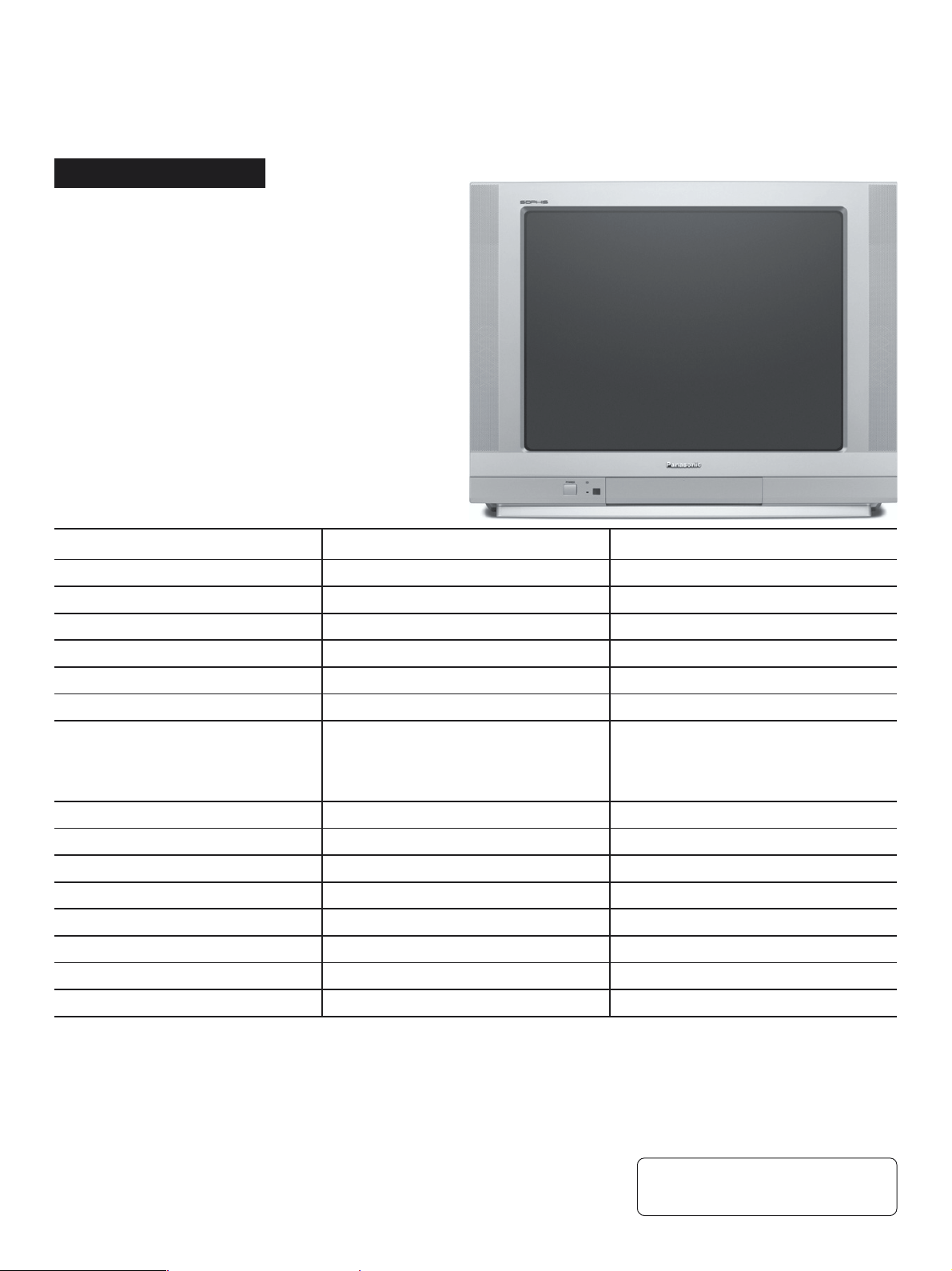
Specifications
TELEVISION
Power source
Consumption
Antenna input jack
Color systems
Tuning system
Channel capability
Picture tube (Diagonal Visual)
Audio system
Video input jack
Audio input jack
Video Outlet
Audio Outlet
Dimension (width, height, depth)
Weight
Remote Control Transmiter:
Power Source 3V (2 AA type batteries)
Infrared Length 9500 A (Angstron)
Number of Buttons 29 keys
Dimensions (W x H x D) (54 x 27 x 135) mm
110/220 V AC, 50/60 Hz automatic switch
TC-20KL03A
79 W
75 ohms - VHF/UHF/CA TV
PAL-M/NTSC/PAL-N
F.S.T.
2 to 13 (VHF)
14 to 69 (UHF)
1 to125 (CATV)
Panablack 48 cm
50 W PMPO
1 (back) + 1 (front)
1 (back) + 1 (front)
1 (back)
1 (back) + 1 (earphone)
600 x 473 x 487 (mm)
17.7 kg
TC-20KL03A
110/220 V AC, 50/60 Hz automatic switch
120 W
75 ohms - VHF/UHF/CATV
PAL-M/NTSC/PAL-N
F.S.T.
2 to 13 (VHF)
14 to 69 (UHF)
1 to125 (CATV)
Panablack 68 cm
82 W PMPO
1 (back) + 1 (front)
1 (back) + 1 (front)
1 (back)
1 (back) + 1 (earphone)
760 x 579 x 512 (mm)
34 kg
Supplied Accessories:
• 1 Remote Control Transmitter
• 1 300Ω/75Ω Balum
• 2 “AA” (or R6) batteries (1.5V; ABNT/IEC)
• 1 Internal antenna (for TC-20KL03A only)
Specifications are subject to change without notice. Weight and dimensions shown are approximate.
®
Panasonic
© 2003 Panasonic da Amazônia S/A
CS Division
Technical Support

TC-20KL03A / TC-29KL03A
Important Safety Notice
Special components are used in this television set which are important for safety. These parts are identified on the schematic
diagram by the symbol . It is essential that these critical parts are replaced whit the manufacturers specified replacement
parts to prevent X-ray radiation, shock, fire or other hazards. Do not modify the original design whitout manufacturers permission.
Table of Contents
Operating Instructions ........................................................................... 04
Feature Summary ................................................................................... 05
The DAC Control Functions and Adjustments for MX5ZB .................... 06
SERVICE MODE:
CHK1 - Options ................................................................................ 06
CHK2 - VCJ Adjustments ................................................................ 07
CHK3 - Pincushion Adjustments ..................................................... 07
CHK4 - White Balance Adjustments ............................................... 07
CHK5 - Stereo Adjustments ........................................................... 07
ADJUSTMENTS:
TEST AND MEASUREMENT EQUIPMENTS ........................................ 08
1- RF AGC CALIBRATION .............................................................. 09
2- VIF DETECTOR OUTPUT LEVEL CONFIRMATION ................ 09
3- BUZZING CONFIRMATION (AUDIO CIRCUIT) ......................... 09
4- ANODE AND HEATER VOLTAGE CONFIRMATION ............... 09
5- PAL COLOR OUTPUT LEVEL ADJUSTMENT ............................ 10
6- NTSC SUB-TINT CALIBRATION ................................................... 10
7- MTS CALIBRATION ........................................................................ 10
8- STEREO SEPARATING ADJUSTMENT ..................................... 11
9- PROTECTION CIRCUIT (SHUTDOWN) OPERATION .............. 11
10- FOCUS CALIBRATION ............................................................. 11
11- VERTICAL DEFLECTION CALIBRATION .................................. 12
12- CRT CUT OFF CALIBRATION ................................................. 12
EEPROM MEMORY MAPS ....................................................................... 13
SCHEMATICS DIAGRAMS:
CRT BOARD (L) ........................................................................................ 15
DVD CONECTION BOARD (D) ................................................................ 16
AV FRONTAL BOARD (G) ....................................................................... 17
REMOTE CONTROL RECEIVER (R) ...................................................... 17
MAI BOARD:
Power Supply ........................................................................................... 18
Microprocessor / YUV / Syntony ............................................................ 20
Audio Signal Process .............................................................................. 22
Vertical / Horizontal Process .................................................................. 24
Audio Output ............................................................................................ 26
General Guidelines
An Isolation Transformer should always be used during the servicing of a
receiver whose chassis is not isolated from the AC power line. Use a
transformer of adequate power rating as this protects the technician from
accidents resulting in personal injury from electrical shocks. It will also
protect the Receiver from being damaged by accidental shorting that may
occur during servicing.
When servicing, observe the original lead dress, especially in the high
voltage circuit. Replace all damaged parts (also parts that show signs of
overheating.)
Always Replace Protective Devices, such as fishpaper, isolation resistors
and capacitors, and shields after servicing the Receiver. Use only
manufacturers recommended rating for fuses, circuit breakers, etc.
High potentials are present when this Receiver is operating. Operation of
the Receiver without the rear cover introduces danger from electrical shock.
Servicing should not be performed by anyone who is not thoroughly familiar with the necessary precautions when servicing high-voltage equipment.
Extreme care should be practiced when Handling the Picture Tube. Rough
handling may cause it to implode due to atmospheric pressure (14.7 lbs
per sq. in). Do not sick or scratch the glass or subject it to any undue
pressure. When handling, use safety goggles and heavy gloves for
protection. Discharge the picture tube by shorting the anode to chassis
ground (not to the cabinet or to other mounting hardware). When
discharging, connect cold ground (i.e. dag ground lead) to the anode with
a well insulated wire or use a grounding probe.
Avoid prolonged exposure at close range to unshielded areas of the picture
tube to prevent exposure to X-ray radiation.
The Test Picture Tube used for servicing the chassis at the bench should
incorporate safety glass and magnetic shielding. The safety glass provides
shieldinf for the tube viewing area against X-ray radiation as well as
implosion. The magnetic shield limits X-ray radiation around the bell of the
picture tube in addition to restricting magnetic effects. When using a picture
tube test jig for service, ensure that the jig is capable of handling 31kV
without causing X-ray radiation.
Before returning a serviced receiver to the owner, the service technician
must thoroughly test the unit to ensure that is completely safe to operatore.
Do not use a line isolation transformer when testing.
CIRCUIT BOARD LAYOUT ....................................................................... 28
IC601 - Voltage and Description ............................................................... 30
IC601 - Layout ............................................................................................ 31
IC2201 - Voltage Table .............................................................................. 31
Signal Waveform ........................................................................................ 32
Exploded View ........................................................................................ 34
Mechanical Replacement Parts List ....................................................... 35
Electrical Replacement Parts List .......................................................... 36
Warning !
It is essential that these critical parts are replaced with
the manufacturers specified replacement parts to prevent X-ray radiation, shock, fire or other hazards.
- 2 -

ABOUT LEAD FREE SOLDER (PbF)
This model uses lead free solder (PbF).
CAUTION:
TC-20KL03A / TC-29KL03A
• Pb free solder has a higher melting point than standard solder; typically thmelting point is 50
- 70°F (300 - 400°C) higher . Please use a high temperature soldering iron. In case of the
soldering iron with temperature control,please set it to 700 ± 20°F (370 ± 10°C).
• Pb free solder will tend to splash when heated too high (about 1100°F/ 600°C).
When soldering or unsoldering, please completely remove all of the solder on the pins or
solder area, and be sure to heat the soldering points with the Pb free solder until it melts
enough.
- 3 -
TC-20KL03A / TC-29KL03A
Operating Instructions
CLICK HERE TO SEE THE COMPLETE OPERATING INSTRUCTIONS
- 4 -
TC-20KL03A / TC-29KL03A
Feature Summary
Model : TC-20KL03A / TC-29KL03A
Chassis : MX5ZB
Country : Brasil
System : 3 systems (PAL-M/PAL-N/NTSC) (PAL-M 50hZ)
Power Source : AC Automatic Voltage Selection 110-240 V AC, 60Hz
Memory : 125 positions
TV Tuning Range : 181 channels (TV / CATV)
Language (OSD) : Portuguese, Spanish and English
Audio System : Stereo
Vertical Magnetic field : -0.1 ±0.03 (BRASIL)
Color temperature : (High Light) x=0.270 ±0.010, y=0.275 ±0.001, Y=155 (nit)
(Low Light) x=0.245 ±0.010, y=0.235 ±0.001, Y=7.0 (nit)
Buzzing confirmation
NTSC color output
Anode (EHT) voltage
Model
TC-20KL03A
Reference Voltage
Contents Test Point
+B VOLTAGE
PAL color output
[A]=C0H, [B]=00H, [C]=00H, [D]=3BH, [E]=00H, [F]=00H, [G]=40H, [H]=09H
TPA12
TPA11
TPA10
TPA21
or TPA41
CRT ANODE
Adjustment Point
A22-3
TPL2
TPL1
TPL1
Memory data
D
C
C
Data
Voltage
140 ± 1,5V
8 ±1V
5 ±1V
215 ±1V
0.5 Vp-p
2.45 ±0.1Vo-p
2.45 ±0.5Vo-p
1.2 ±0.5Vo-p
26.5 +0.7 / -1.5 (kV)
TC-29KL03A
[A]=C0H, [B]=00H, [C]=00H, [D]=3BH, [E]=00H, [F]=00H, [G]=40H, [H]=09H
- 5 -
TC-20KL03A / TC-29KL03A
THE DAC CONTROL FOR MX5ZB FUNCTIONS ADJUSTMENTS
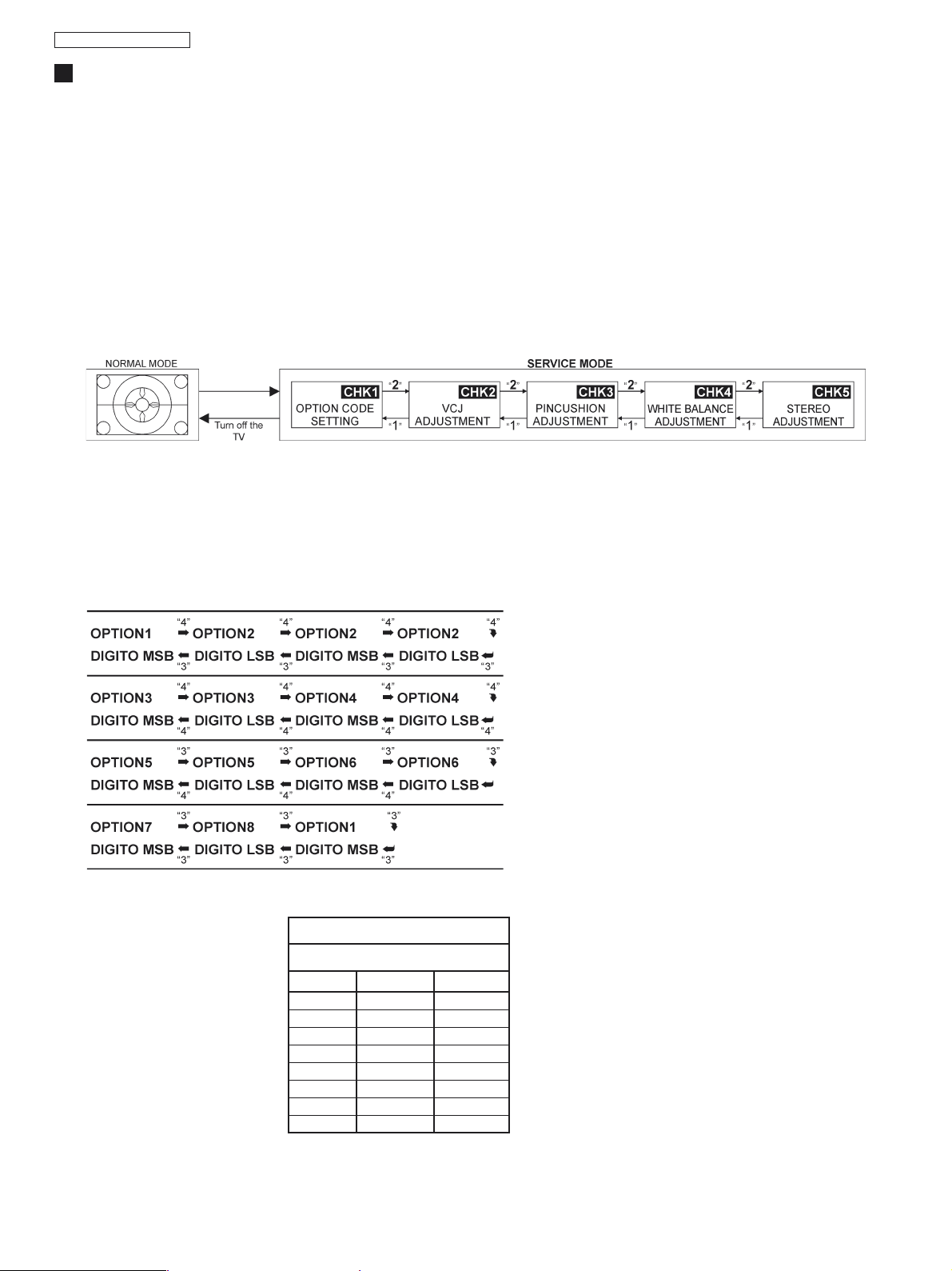
HOW TO ENTER IN THE SERVICE MODE:
1- Set the “OFF TIMER” to 30 minutes.
2- Press simultaneously RECALL key on the remote control and VOL(-) button on the unit.
After some seconds, the expression “CHK” should appear on the superior right side of the screen. (To change the
memory data, to press MUTE and e VOLUME(_) simultaneously still with OSD in the way “CHK1”. The key “4” it
moves forward in the memory, and the key “3” it retreats in the memory
Note: To alter in the way CHK1 for the CHK2, CHK3 or CHK4 mode, press the key “2” to move forward and the
key “1” to retreat, as illustrated below.
TO EXIT SERVICE MODE AND RETURN TO THE NORMAL MODE:
Press the “NORMAL” key on the remote control unit or turn off the TV.
CHK1 - OPTIONS
Being in the way CHK1, it will be possible to adjust the options below:
CHK1 OPTIONS T ABLE
MEDIUM VALUES
OPTION
OPTION 1
OPTION 2
OPTION 3
OPTION 4
OPTION 5
OPTION 6
OPTION 7
OPTION 8
TC-20KL03A
C0
00
00
3B
00
00
40
9
TC-29KL03A
C0
00
00
3B
00
00
40
09
Note:
To select the option, type “4” to move forward
and “3” to retreat.
After having selected the wanted option, adjust
it pressing the “VOL(_)” or “VOL(+)” keys.
Press “0” to memorize the adjustment.
- 6 -
TC-20KL03A / TC-29KL03A
CHK2 - VCJ ADJUSTMENTS
In the CHK2 mode is possible to adjust the items of the table.
Note:
T o select the option, type “4” to move forward and “3” to retreat.
After having selected the wanted option, adjust it pressing the “VOL(_)”
or “VOL(+)” keys.
Press “0” T o memorize the adjustment.
CHK3 - PINCUSHION ADJUSTMENTS
In the CHK2 mode is possible to adjust the items of the table.
Note:
T o select the option, type “4” to move forward and “3” to retreat.
After having selected the wanted option, adjust it pressing the “VOL(_)”
or “VOL(+)” keys.
Press “0” T o memorize the adjustment.
CHK2 TABLE
MEDIUM VALUES
ITEM
RF AGC
SUB COULOR
SUB TINT
CHK3 TABLE
MEDIUM VALUES
ITEM
V-SLOP
V-SHIFT 50Hz
V-SHIFT 60Hz
V-AMP 50Hz
V-AMP 60Hz
H-SHIFT
EW-WIDTH
EW-PARA
EW-UP COR
EW-LOW COR
EW-TRAPE
H-PARA
H-BOW
S-CORR-50Hz
S-CORR-60Hz
V-ZOOM-50Hz
V-ZOOM-60Hz
OSD H-POS
OSD V-POS-50Hz
OSD V-POS-60H
TC-20KL03A
23
35
31
TC-20KL03A
35
1
1
27
34
34
23
26
15
15
43
27
32
18
18
25
25
2
27
18
TC-29KL03A
22
37
32
TC-29KL03A
36
2
1
17
23
31
23
26
15
15
43
27
32
26
25
25
25
3
25
21
CHK4 - WHITE BALANCE ADJUSTMENTS
In the CHK2 mode is possible to adjust the items of the table.
Note:
T o select the option, type “4” to move forward and “3” to retreat.
After having selected the wanted option, adjust it pressing the “VOL(_)”
or “VOL(+)” keys.
Press “0” T o memorize the adjustment.
To obtain a horizontal line without vertical sweeping, press the “5” key
when the OSD indicates the marked mode. To return to the “CHK4”
mode, press “5” again.
CHK5 - STEREO ADJUSTMENTS
- 7 -
CHK4 TABLE
MEDIUM VALUES
ITEM
R-CUT
G-CUT
S-BRT
SUB CONTRAST
R-DRIVE
G-DRIVE
B-DRIVE
RGB CONTRASTE
T ABELA CHK5
VALORES MÉDIOS
ITEM
INPUT LEVEL
LB SEPARATION
HB SEPARATION
TC-20KL03A
29
26
26
21
26
31
33
7
TC-20KL03A
40
10
27
TC-29KL03A
33
25
25
21
27
31
35
11
TC-29KL03A
41
9
28

TC-20KL03A / TC-29KL03A
ADJUSTMENTS
TEST AND MEASUREMENT EQUIPMENTS
To do all these electrical adjustments, the following equipment is required:
• Dual-Trace Oscilloscope
Voltage Range: 0.001 V to 50 V/Div.
Frequency Range: DC to 50 MHz
Probes: 10:1, 1:1
• NTSC Video Pattern Generator
• DVM (Digital Volt Meter)
• MTS/SAP Signal Generator
• (TV Multi-Channel Sound Modulator (U.S.A.))
• Plastic Tip Driver and Non-Metal Driver
• Isolation Transformer (Variable)
• Degaussing Coil
• White Pattern Generator
• Audio Generator
- 8 -
ADJUSTMENTS
ITEM / PREPARATION PROCEDURE
TC-20KL03A / TC-29KL03A
1- RF AGC ADJUSTMENT
1. Supply a color bar pattern and adjust the RF input signal
of to 69 dB.
2. Connect the digital multimeter in TPA15.
2- VIF DETECTOR OUTPUT LEVEL
CONFIRMATION
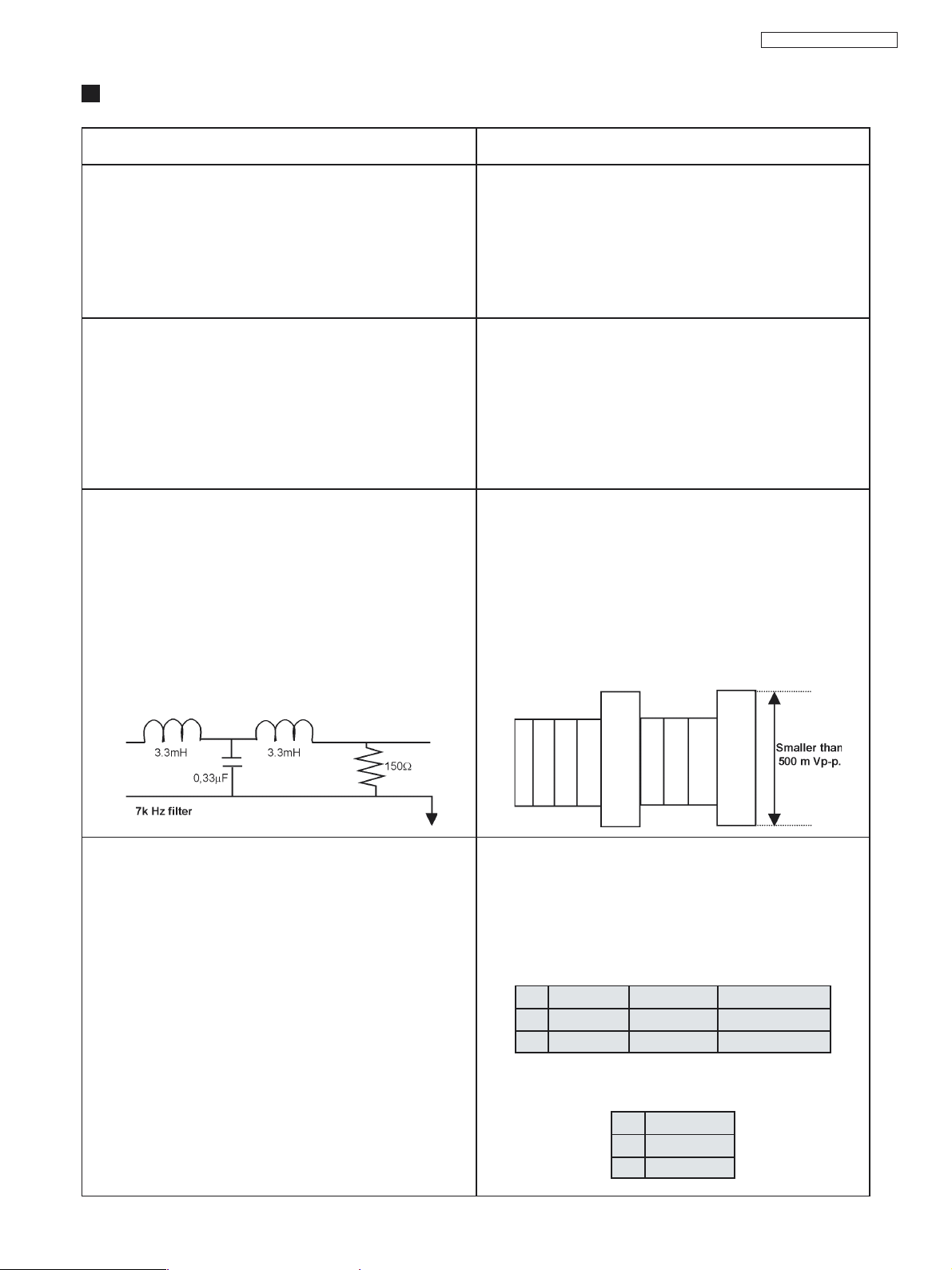
3- BUZZING CONFIRMATION
(AUDIO CIRCUIT)
1. Connect the oscilloscope with a 7kHz filter between
TPA41 and ground or between the speakers terminals
2. Adjust the sound to the maximum..
3. BALANCE : CENTER
SURROUND : OFF
AVL : OFF
SOUND MENU : DIALOGUE
ADJUSTMENT:
1. Select RF AGC in the CHK2 service mode.
2. Adjusts "RF AGC" pressing VOL(+) or (-) until obtaining
2.2±0.1V in TPA20.
3. Increase the input level by +2 dB and confirm that the
voltage decrease.
CONFIRMATION:
1. Install the chassis in the VIF calibration JIG and tune in a
63 dBU colorbar sign (75W open).
2. To connect the oscilloscope in TPA33.
3. To confirm that the output video sign is 1.05 ± 0.15 Vp-p
in TPA 33.
CONFIRMATION:
1. Supply a colorbar signal channel 2, with local frequency
adjusted and the AFC turned on (Channel with sound
bearer and without modulation).
2. Assure that the width in the buzzing waveform is smaller
than 500 m Vp-p.
4- ANODE AND HEA TER VOL T AGE CONFIRMA TION
1. Supply a crosshatch signal.
2. Adjust the bunch current in zero. (0 beam).
3. Adjust “SCREEN VR” and “CONTRAST” to minimum.
CONFIRMATION
1. Connect a voltage meter between TPA12 and ground.
Confirm that the voltage +B is within a range of 140.5V±
1.5V
2. Connect a high frequency voltage meter (VRMS.) among
the heater, and confirm that the voltage is as below:
20” PHILIPS A48EAK01X 6,15 ± 0,20 Vrms
20” SAMSUNG A48KRD89X 6,30 ± 0,24 Vrms
29” PHILIPS A68AJB82X 6,30 ± 0,24 Vrms
3. Connect the high voltage meter in the CRT anode pin,
and confirm that the high voltage is within a range of [A].
CRT [A] KV
29” 30,5 ~ 27,6
20” 27,2 ~ 25,0
- 9 -

TC-20KL03A / TC-29KL03A
ADJUSTMENTS
ITEM / PREPARATION PROCEDURE
5- PAL COLOR OUTPUT SIGNAL ADJUSTMENT
1. Supply a color bar signal and adjust the local frequency.
2. Adjust “IMAGE” to DYNAMIC NORMAL, “CONTRAST” to
63 and “SUB-CONTRAST” to 21.
3. Adjust the “COLOR FOR CHANNEL” level to NORMAL.
4. Set the CHK2 service mode option, press “5” on the remote
control unit and confirm that OSD becomes blue (AKB
turned off).
5. Connect a short circuit jumper between TPA10 and TP A20.
6. Adjust [A] for 2.3 ± 0.2V through the BRIGHT control
variation in the test point TPL2.
7. Confirm:
CRT 20” 29”
RGB Contrast 7 DAC 9 DAC
{354} 17 19
8. Fix G-DRIVE GAIN, R-DRIVE GAIN and B-DRIVE GAIN
data in 1FH or 31 DAC.
R-DRIVE GAIN: [SLV(8A), SUB (16)]
G-DRIVE GAIN: [SLV(8A), SUB (17)]
B-DRIVE GAIN: [SLV(8A), SUB (18)]
6- NTSC SUB-TINT CALIBRATION
CALIBRATION:
1. Connect the oscilloscope in TPL2 (G-OUT) with a 10KΩ
resistor and adjust CONTRAST, so that the [B] waveform
it is 2.6±0.1V according to fig. 1.
2. Adjust SUB-COLOR to obtain 2,45±0.1V in [D]
according to fig. 1.
3. Connect the oscilloscope in TPL1 (R-OUT) with a 10KΩ
resistor and confirm that the [C] waveform it is 2.45±0.1V
according to fig. 2.
4. Remove the jumper between TPA10 and TPA20, press
the key 5 (AKB ON) and confirm that OSD becomes
white.
Fig. 1
A = 2.3 ±0.2Vo-p
B = 2.4±0.1V
D = 2.45±0.1V
Fig. 2
A = 2.3 ±0.2Vo-p
C = 2.45±0.1V
NTSC 3.58 COLOR SYSTEM CALIBRATION
1. Connect the oscilloscope in TPL2 (R-OUT) with a 10KW
resistor.
2. Supply a Rainbow signal (NTSC 3.58 MHz) through
VIDEO IN.
3. Adjust IMAGE to DYNAMIC NORMAL.
4. Adjust COLOR FOR CHANNEL to NORMAL.
5. Set the CHK2 service mode option, press 5 on the
remote control unit and confirm that OSD becomes blue
(AKB turned off).
6. Connect a short circuit jumper between TPA10 and
TPA20.
7- MTS CALIBRATION
1. Connect the RMS voltage meter through the JIG filter in
TPA44.
2. Connect the RF generator in the tuner terminal.
3. Adjust AVL to ON.
1. Adjust [C] for 5.0±0.2V through the BRIGHT control
variation (CHK2) according to fig. 1.
2. Adjust the NTSC SUB-TINT level according to fig. 1
positions 2, 3 and 4.
3. Remove the jumper.
4. Press 5 and confirm that OSD becomes white (AKB
turned on).
Fig. 1 Fig. 2
ADJUSTMENT:
1. Supply the signal through RF antenna input.
VIDEO: 100 IRE FLAT FIELD , 30% of modulation.
AUDIO: 300 Hz , 100% of modulation, monoaural (70 ±
5dB, open, 75W, P/S 10dB) 75 µs with pre-enfasis OFF.
2. Adjust INPUT LEVEL (CHK5) to obtain 106 ± 6 mVrms
in the RMS voltage meter.
- 10 -
ADJUSTMENTS
ITEM / PREPARATION PROCEDURE
TC-20KL03A / TC-29KL03A
8- MTS CALIBRATION
STEREO SEPARATING ADJUSTMENT
1. Connect the oscilloscope in TPA42.
2. Connect the RF generator in the tuner terminal.
3. Adjust AVL to ON.
9- PROTECTION CIRCUIT (SHUTDOWN)
OPERATION
1. Supply a CROSS-HATCH signal.
2. Adjust CONTRAST and BRIGHT controls to minimum.
ADJUSTMENT:
1. Select stereo mode in the audio menu.
2. Supply the signal through RF antenna input:
VIDEO: 100 IRE FLAT FIELD, 30% of modulation
AUDIO: 300 Hz, 30% of modulation, stereo (left only)
(70 ± 5 dB, open, 75W, P/S 10dB)
3.Adjust LB SEPARATION (CHK5) so that the sign
visualized in the oscilloscope is minimum.
4. Supply the signal through RF antenna input:
VIDEO: 100 IRE FLAT FIELD, 30% of modulation
AUDIO: 3 kHz, 30% of modulation, stereo (left only) (70
± 5 dB, open, 75W, P/S 10dB)
5. Adjust HB SEPARATION (CHK5) so that the sign
visualized in the oscilloscope is minimum
6. Repeat the steps 2 to 5.
CONFIRMATION:
1. Connect the voLtmeter in TPA22 and confirm that the
voltage is smaller than [A].
2. Connect a DC source in TPA22 and confirm that the
protection circuit doesn't act when the voltage is [B].
3. Confirm that the protection circuit acts with smaller
voltage than [C].
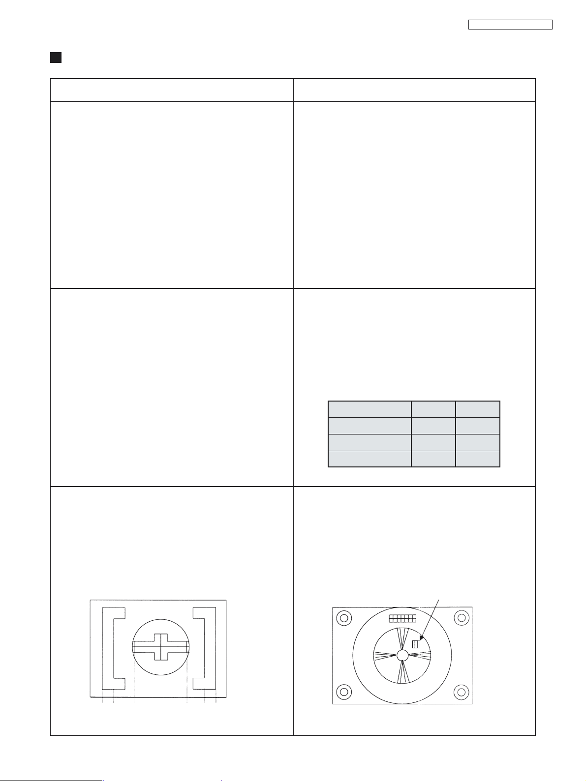
10- FOCUS CALIBRATION
• Assure that the SUB-BRIGHTNESS adjustment has been
done.
1. Supply a Philips or monoscope pattern signal.
2. Adjust MENU OF IMAGE to DYNAMIC NORMAL.
Condition / CRT 20 pol 29 pol
[A] 22,03V 24,12V
[B] 23,02V 24,50V
[C] 25,52V 27,56V
CALIBRATION:
1. Adjust the FOCUS variable resistor for the point of
better adjustment.
with PHILIPS signal .... take as reference for
adjustment the third vertical line (fig. 1).
with MONOSCOPE signal in the number 4 (fig.2).
4
1 2 3
Fig. 1
3 2 1
Fig. 2
- 11 -
TC-20KL03A / TC-29KL03A
AJUSTMENTS
ITEM / PREPARATION PROCEDURE
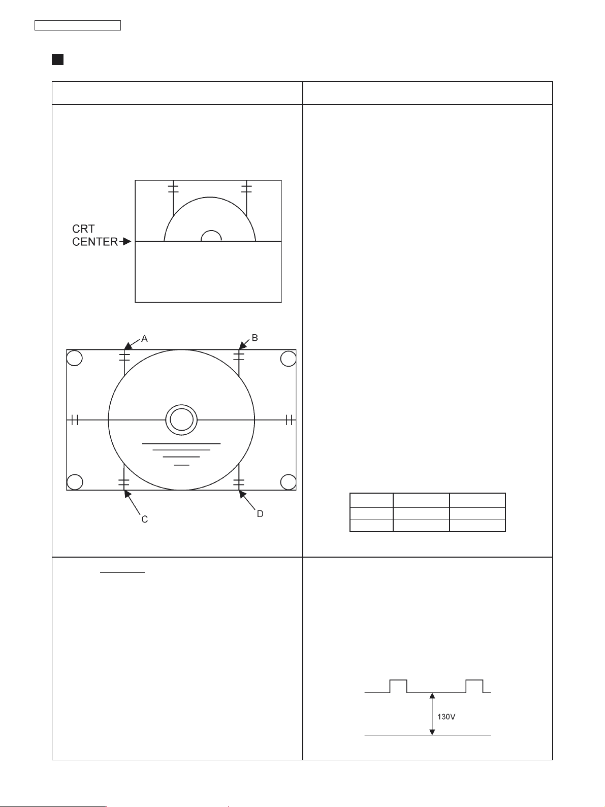
11- VERTICAL DEFLECTION CALIBRATION AND
CONFIRMATION
1. Adjust IMAGE to DYNAMIC NORMAL
Fig. 1
S-CORR CONFIRMATION AND CALIBRATION
1) Confirmation in 50Hz
1. Supply a PHILIPS PAL-N signal.
2. Confirm that S-CORR 50Hz is in [18] DAC.
2) Confirmation in 60Hz
1. Supply a MONOSCOPE signal.
2. Confirm that S-CORR 60Hz is in [18] DAC.
3) V-SLOPE calibration
1. Supply a MONOSCOPE signal.
2. Adjust V_SLOPE (CHK3) so that the beginning of the
black part of the image be aligned with the center of
the CRT as Fig. 1.
4) VERTICAL CENTRALIZATION 50 HZ CALIBRATION
1. Supply a PAL-N Philips signal.
2. Adjust V-SHIFT 50Hz (CHK3) so that the Philips
patterns center it is in the CRT center.
5) VERTICAL CENTRALIZATION 60 HZ CALIBRATION
1. Supply a MONOSCOPE signal.
2. Adjust V-SHIFT 60Hz (CHK3) so that the monoscope
patterns it is in the CRT center
6) VERTICAL HEIGHT (V-AMP 50HZ) CALIBRATION
1. Supply a PHILIPS PAL-N signal.
2. Adjust V-AMP-50Hz (CHK3) so that the Philips patterns
circle height be the same dimension of the width.
Fig. 2
12- CRT CUT OFF CALIBRATION
1. Supply a WINDOWS signal.
2. Position DACs with the data below:
BRT e S-BRT > 32H
RGB CONTRAST > 09H (29 pol) e 07H (20 pol)
SUB-CONTRAST > 21H
R,G,B DRIVE > 31H
R,G CUT > 31H
7) VERTICAL HEIGHT (V-AMP 60HZ) CALIBRATION
1. Supply a MONOSCOPE signal.
2. Adjust V-AMP-60Hz (CHK3) so that, in the Fig.2, be:
CRT->
C,D
A,B
3. MEMORIZE in EEPROM.
20
1.9 ~ 2.2
1.5 ~ 2.3
29
1.5 ~ 2.0
1.5 ~ 1.6
CALIBRATION:
1. Press 5 (AKB OFF) and confirm that OSD becomes blue.
2. Connect the oscilloscope in TPL7 and adjust BRT to obtain
130V as in the Fig. 1 below.
3. Adjust the SCREEN to obtain in the color analyzer
Y = 1.0 +1.0
-0.5
4. Press 5 (AKB OFF) and confirm that OSD becomes blue.
white.
Fig. 1
- 12 -
EEPROM MEMORY MAPS
Observation:
*/XX : Data subjects to alterations in the calibration process (values no fixed).
@ : Data of channels
[A-M] : Corresponds to the specification of specific production of each model.
: Fixed data (it doesn't alter in the calibration process)
SUB-ADDRESS
00: Any larger value than 63H will select the channel 0.
01: Bit 1, Bit 2, Bit 3, Bit 5, Bit 6 should be fixed to 0
2: Bit 4, Bit 5, Bit 6 should be 0 and Bit 7 should be 1.
N = AA = ON / 55 OFF (ADJUST: PRESET)
O = AA = ON/ 55 OFF (CLOSED CAPTION)
P = 0 – ENGLISH / CHINESE
1 – SPANISH / PORTUGUESE / ENGLISH
2 – ENGLISH / TAGLISH
3 – ENGLISH
TC-20KL03A / TC-29KL03A
[G] - STEREO
00 – NICAM STEREO (TDA9875)
01 – AV STEREO (TDA9859)
02 – US STEREO
03 – AV STEREO (TDA9870)
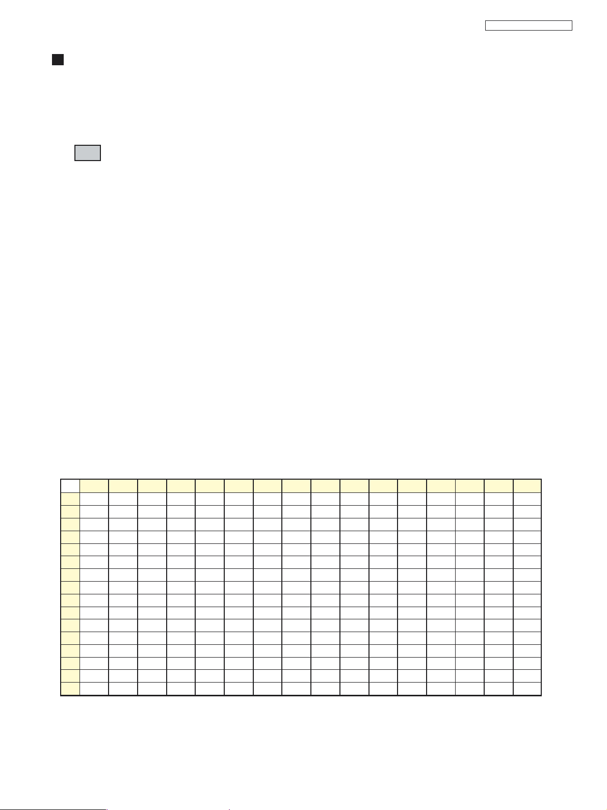
TABLE A0 (0XX)
00 01 02 03 04 05 06 07 08 09 0A 0B 0C 0 D 0E 0F
00 02 00 06 01 00 06 02 00 06 03 00 06 04 00 06 05
10 00 06 06 00 06 07 00 06 08 00 06 09 00 06 0A 00
20 06 0B 00 06 0C 00 06 0D 00 06 0E 00 06 0F 00 06
30 10 00 06 11 00 06 12 00 06 13 00 06 14 00 06 15
40 00 06 16 00 06 17 00 06 18 00 06 19 00 06 1A 00
50 06 1B 00 06 1C 00 06 1D 00 06 1E 00 06 1F 00 06
60 20 00 06 21 00 06 22 00 06 23 00 06 24 00 06 25
70 00 06 26 00 06 27 00 06 28 00 06 29 00 06 2A 00
80 06 2B 00 06 2C 00 06 2D 00 06 2E 00 06 2F 00 06
90 30 00 06 31 00 06 32 00 06 33 00 06 34 00 06 35
A0 00 06 36 00 06 37 00 06 38 00 06 39 00 06 3A 00
B0 06 3B 00 06 3C 00 06 3D 00 06 3E 00 06 3F 00 06
C0 40 00 06 41 00 06 42 00 06 43 00 06 44 00 06 45
D0 00 06 46 00 06 47 00 06 48 00 06 49 00 06 4A 00
E0 06 4B 00 06 4C 00 06 4D 00 06 4E 00 06 4F 00 06
F0 50 00 06 51 00 06 52 00 06 53 00 06 54 00 06 55
- 13 -
TC-20KL03A / TC-29KL03A
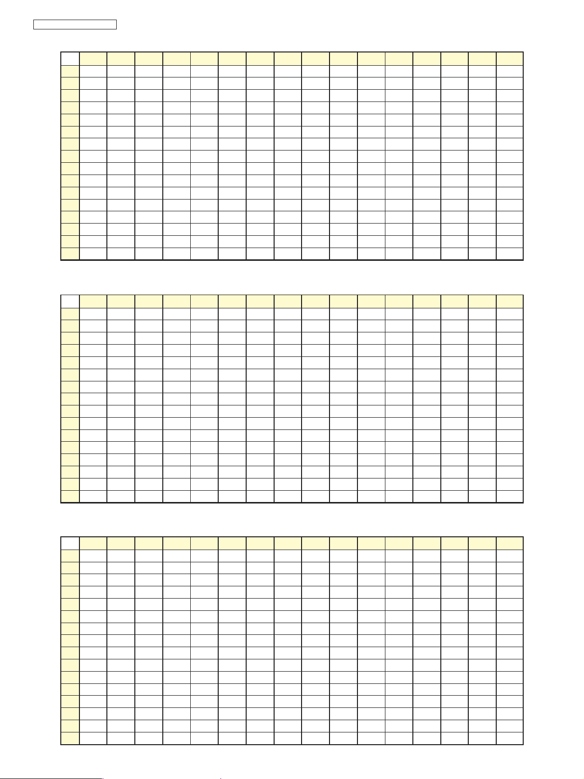
TABLE A2 (1XX)
00 01 02 03 04 05 06 07 08 09 0A 0B 0C 0D 0E 0F
00 00 06 56 00 06 57 00 06 58 00 06 59 00 06 5A 00
10 06 5B 00 06 5C 00 06 5D 00 06 5E 00 06 5F 00 06
20 60 00 06 61 00 06 62 00 06 63 00 06 64 00 06 65
30 00 06 66 00 06 67 00 06 68 00 06 69 00 06 6A 00
40 06 6B 00 06 6C 00 06 6D 00 06 6E 00 06 6F 00 06
50 70 00 06 71 00 06 72 00 06 73 00 06 74 00 06 75
60 00 06 76 00 06 77 00 06 78 00 06 79 00 06 7A 00
70 06 7B 00 06 7C 00 06 7D 00 06 00 00 00 00 00 00
80 00 00 00 00 00 00 00 00 00 00 00 00 00 00 00 00
90 00 00 00 00 00 00 00 00 00 00 00 00 00 00 00 00
A0 06 00 00 00 00 00 00 00 00 00 00 00 00 00 00 00
B0 00 00 00 00 00 00 00 00 00 00 00 00 00 00 00 00
C0 00 00 00 00 00 00 00 00 00 00 00 00 00 00 00 00
D0 00 00 00 00 00 00 00 00 00 00 00 00 00 00 00 00
E0 00 00 00 00 00 00 00 00 00 00 00 00 00 00 00 00
F0 00 00 00 00 00 00 00 00 00 00 00 00 00 00 00 00
TABLE A4 (2XX)
00 01 02 03 04 05 06 07 08 09 0A 0B 0C 0D 0E 0F
00 02 00 A5 5A 00 01 01 00 00 08 00 04 00 00 01 00
10 00 00 00 00 00 00 00 00 20 00 00 00 00 00 00 00
20 00 00 00 00 00 00 00 00 00 00 00 00 00 00 00 00
30 00 00 00 00 00 00 00 00 00 00 00 00 00 00 00 00
40 00 00 00 00 00 00 00 00 00 00 00 00 00 00 00 00
50 20 20 20 3F 2D 20 20 20 2D 20 1E 20 20 23 1E 20
60 2D 2A 34 32 24 24 00 00 00 20 20 20 00 00 00 00
70 00 00 00 00 00 00 00 00 00 00 00 00 00 00 78 BB
80 20 20 20 3F 2D 20 20 20 2D 20 1E 20 20 23 1E 34
90 32 24 24 00 00 00 2D 2A 00 00 00 00 00 00 00 00
A0 00 00 00 00 00 00 00 00 00 00 00 00 00 00 00 00
B0 *1 *2 *3 0C 00 1B 00 00 00 40 40 40 00 00 00 00
C0 00 00 00 00 00 00 00 00 00 00 00 00 00 00 00 00
D0 0C 10 15 04 06 06 00 04 00 00 00 00 00 00 00 00
E0 00 00 00 00 00 00 00 00 [A] [B] [C] [D] [E] [F] [G] [H]
F0 00 00 18 20 15 1A 00 00 00 00 00 00 00 A5 3F A5
TABLE A6 (3XX)
00 01 02 03 04 05 06 07 08 09 0A 0B 0C 0D 0E 0F
00 00 00 00 00 00 00 00 00 00 00 00 00 00 00 00 00
10 00 00 00 00 00 00 00 00 00 00 00 00 00 00 00 00
20 00 00 B6 B7 20 10 28 18 B0 00 00 00 00 00 00 00
30 1B 20 00 22 17 1A 0F 0F 2B 24 1F *4 20 19 1F 1F
40 1F 1F 1F 00 06 00 00 00 10 24 C0 00 2A 00 34 20
50 30 21 02 4A *5 44 00 00 00 00 00 *6 FE 00 00 00
60 02 FF 1C *7 19 00 00 00 00 00 00 00 00 00 00 00
70 00 00 00 00 00 00 00 00 10 00 00 00 00 00 00 00
80 00 00 00 00 00 00 00 0E 11 0D 06 0C 07 0C 02 00
90 09 00 FA F7 00 00 00 0A F8 *8 00 00 00 00 00 03
A0 01 03 02 03 03 00 34 00 00 00 20 63 03 00 20 30
B0 4A 49 4B 00 33 00 00 FF FC 04 05 05 FC F8 00 F2
C0 20 07 4F 40 40 00 00 00 00 00 00 00 00 00 00 00
D0 86 *9 *10 03 00 00 00 05 *11 *12 *13 F2 03 00 00 00
E0 20 15 02 00 00 08 00 00 00 00 00 00 00 00 00 00
F0 00 00 00 00 00 00 00 00 00 00 00 00 00 00 00 11
- 14 -
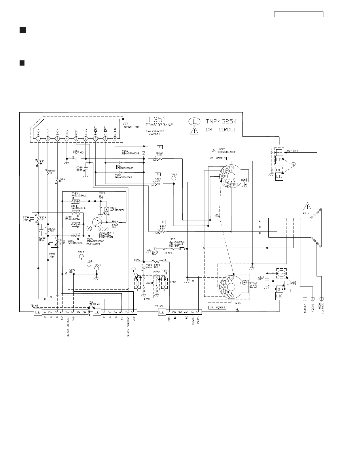
SCHEMA TIC DIAGRAMS
CRT BOARD SCHEMA TIC DIAGRAM (L)
TC-20KL03A / TC-29KL03A
- 15 -
 Loading...