

Page 1

TQB8E2999
English
Panasonic¡Panasonic¡Panasonic¡Panasonic¡Panasonic¡P
anasonic¡Panasonic¡Panasonic¡Panasonic¡Panasonic¡Pa
nasonic¡Panasonic¡Panasonic¡Panasonic¡Panasonic¡Pan
asonic¡Panasonic¡Panasonic¡Panasonic¡Panasonic¡Pana
sonic¡Panasonic¡Panasonic¡Panasonic¡Panasonic¡Panas
onic¡Panasonic¡Panasonic¡Panasonic¡Panasonic¡Panaso
nic¡Panasonic¡Panasonic¡Panasonic¡Panasonic¡Panasoni
c¡Panasonic¡Panasonic¡Panasonic¡Panasonic¡Panasonic¡
Panasonic¡Panasonic¡Panasonic¡Panasonic¡Panasonic¡P
anasonic
nasonic¡Panasonic¡Panasonic¡Panasonic¡Panasonic¡Pan
asonic¡Panasonic¡Panasonic¡Panasonic¡Panasonic¡Pana
sonic¡Panasonic¡Panasonic¡Panasonic¡Panasonic¡Panas
onic¡Panasonic¡Panasonic¡Panasonic¡Panasonic¡Panaso
nic¡Panasonic¡Panasonic¡Panasonic¡Panasonic¡Panasoni
c¡Panasonic¡Panasonic¡Panasonic¡Panasonic¡Panasonic¡
Panasonic¡Panasonic¡Panasonic¡Panasonic¡Panasonic¡P
anasonic¡Panasonic¡Panasonic¡Panasonic¡Panasonic¡Pa
nasonic¡
asonic¡Panasonic¡Panasonic¡Panasonic¡Panasonic¡Pana
sonic¡Panasonic¡Panasonic¡Panasonic¡Panasonic¡Panas
onic¡Panasonic¡Panasonic¡Panasonic¡Panasonic¡Panaso
nic¡Panasonic¡Panasonic¡Panasonic¡Panasonic¡Panasoni
c¡Panasonic¡Panasonic¡Panasonic¡Panasonic¡Panasonic¡
Panasonic¡Panasonic¡Panasonic¡Panasonic¡Panasonic¡P
anasonic¡Panasonic¡Panasonic¡Panasonic¡Panasonic¡Pa
nasonic¡Panasonic¡Panasonic¡Panasonic¡Panasonic¡Pan
asonic¡Panasonic
sonic¡Panasonic¡Panasonic¡Panasonic¡Panasonic¡Panas
onic¡Panasonic¡Panasonic¡Panasonic¡Panasonic¡Panaso
nic¡Panasonic¡Panasonic¡Panasonic¡Panasonic¡Panasoni
c¡Panasonic¡Panasonic¡Panasonic¡Panasonic¡Panasonic¡
T C --- 1 4 J R 1
Panasonic¡Panasonic¡Panasonic¡Panasonic¡Panasonic¡P
anasonic¡Panasonic¡Panasonic¡Panasonic¡Panasonic¡Pa
nasonic¡Panasonic¡Panasonic¡Panasonic¡Panasonic¡Pan
asonic¡Panasonic¡Panasonic¡Panasonic¡Panasonic¡Pana
sonic¡Panasonic¡
onic¡Panasonic¡Panasonic¡Panasonic¡Panasonic¡Panaso
nic¡Panasonic¡Panasonic¡Panasonic¡Panasonic¡Panasoni
c¡Panasonic¡Panasonic¡Panasonic¡Panasonic¡Panasonic¡
Panasonic¡Panasonic¡Panasonic¡Panasonic¡Panasonic¡P
anasonic¡Panasonic¡Panasonic¡Panasonic¡Panasonic¡Pa
nasonic¡Panasonic¡Panasonic¡Panasonic¡Panasonic¡Pan
asonic¡Panasonic¡Panasonic¡Panasonic¡Panasonic¡Pana
sonic¡Panasonic¡Panasonic¡Panasonic¡Panasonic¡Panas
onic¡Panasonic¡Panasonic
nic¡Panasonic¡Panasonic¡Panasonic¡Panasonic¡Panasoni
c¡Panasonic¡Panasonic¡Panasonic¡Panasonic¡Panasonic¡
Panasonic¡Panasonic¡Panasonic¡Panasonic¡Panasonic¡P
anasonic¡Panasonic¡Panasonic¡Panasonic¡Panasonic¡Pa
nasonic¡Panasonic¡Panasonic¡Panasonic¡Panasonic¡Pan
Operating Instructions
asonic¡Panasonic¡Panasonic¡Panasonic¡Panasonic¡Pana
sonic¡Panasonic¡Panasonic¡Panasonic¡Panasonic¡Panas
Please read these instructions before operating your set and retain them for future reference
onic¡Panasonic¡Panasonic¡Panasonic¡Panasonic¡Panaso
nic¡Panasonic¡Panasonic¡
c¡Panasonic¡Panasonic¡Panasonic¡Panasonic¡Panasonic¡
¡Panasonic¡Panasonic¡Panasonic¡Panasonic¡Pa
Panasonic¡Panasonic¡Panasonic¡Panasonic¡Pan
¡Panasonic¡Panasonic¡Panasonic¡Pana
Colour Television
Panasonic¡Panasonic¡Panasonic¡Panas
Contrast Auto Tracking System
¡Panasonic¡Panasonic¡Panaso
Panasonic¡Panasonic¡Panasoni
Page 2

Dear Panasonic Customer,
Welcome to the Panasonic family of customers. We hope that you have many years of enjoyment from your new colour television.
The best way to understand the features of this television is to read this book thoroughly, before operating the set.
This television has a low power consumption making it very cost effective to run.
To this end, the standby power consumption is merely 1 watt.
CONTENTS
D Accessories 4................................
D Fitting Remote Control Batteries 4..............
D Installation and Set---up 5......................
D Location of Controls 7.........................
D Menu Operation 8............................
D Audio / Video Connections 12...................
D VCR and Satellite Receiver Installation 13.........
D Trouble---shooting 14..........................
D General Information 14.........................
D Specifications 15.............................
D Scart Terminal Information 15...................
2
Page 3

WARNINGS AND PRECAUTIONS
D This T.V. is designed to operate on A.C. 220 --- 240V, 50Hz
and is capable of receiving the PAL I transmission
standard.
D Do not expose this TV set to rain or excessive moisture.
D WARNING: HIGH VOLTAGE !
Do not remove the rear cover, there are no user
serviceable parts inside.
D Avoid exposing the TV set to direct sunlight or other
sources of heat.
D Remove the mains plug from the wall socket when the TV
set is not to be used for a prolonged period oftime.Donot
pull the power cable to remove the mains plug from the
socket, always remove it by the plug.
FOR YOUR SAFETY PLEASE READ THE FOLLOWING CAREFULLY
This appliance is supplied with a fitted three pin mains plug for your safety and convenience. A 5 amp fuse is fitted in this plug. If
the fuse is replaced then the replacement fuse must be 5 amp rated and should be approved by ASTA or BSI to BS1362.
Check for the ASTA mark
or the BSI mark on the body of the fuse.
D CABINET AND PICTURE TUBE CARE
Remove the mains plug from the wall socket. The cabinet
and picture tube can be cleaned with a soft cloth
moistened with mild detergent and water. Do not use
solutions containing benzol or petroleum. TV sets can
produce static electricity, care must be taken whenever
touching the TV screen.
D Adequate ventilation is essential to prevent failure of
electrical components. We recommend that a gap of at
least 5cm is left all around this TV even when it is placed
inside a cabinet or between shelves.
If the fitted plug has a removable fuse cover you must ensure that it is refitted when the fuse is replaced. If you lose the fuse cover the plug
must not be used until a replacement cover is obtained.
Replacement fuse covers can be purchased through your local Panasonic dealer.
Theplugfittedtothisapplianceincorporates a mains filter circuit. If this is removed or
replaced with a non ---filtered mains plug this television will no longer meet the
European standards for Electromagnetic Compatibility (EMC). If the fitted plug is
unsuitable for the socket outlet in your home an appropriate adapter should be used.
Nonetheless,ifthefittedplugisreplaced,thefuseshouldbetakenoutandthecut---off
plug disposed of safely. There is danger of severe electrical shock if the cut off plug is
inserted into any 13amp socket.
If a new plug is to be fitted please observe the wiring code as shown below.
If in any doubt please consult a qualified electrician.
How to replace the fuse :
Lift out the removable fuse compartment with a screwdriver and replace the fuse, then refit
securely into the mains plug.
IMPORTANT :---
As the colours of the wires in the mains lead of this appliance may not correspond to the markings identifying the terminals in your plug,
proceed as follows :---
1. The BLUE
2. The BROWN
The wires in the mains lead of this appliance are coloured in accordance with the following code :---
BLUE : NEUTRAL BROWN : LIVE
wire must be connected to the terminal marked ‘N’ or coloured black.
wire must be connected to the terminal marked ‘L’ or coloured red.
Important Note :
The layout of the mains plug used
may differ from this illustration.
IMPORTANT NOTE : Under no circumstances should either of these wires be connected to the Earth terminal of the three pin plug,
marked with the letter ‘E’ or the earth symbol ( ).
3
Page 4
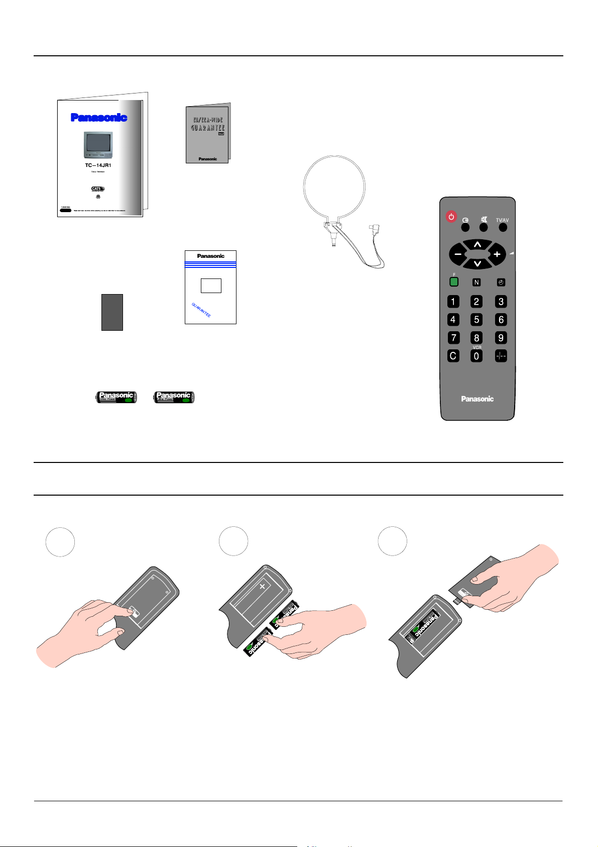
ACCESSORIES
Check that you have the accessories and items shown
Operating Instruction
book
Questionnaire
TV Guarantee
Colour
Tube
CRT Guarantee
Remote Control Transmitter.
Remote Control Transmitter
EUR511380
Loop Antenna
TSA8E001
Batteries for the
(2 x R6 (UM3) size)
FITTING REMOTE CONTROL BATTERIES
1
Slide off the battery cover
D Make sure that the batteries are fitted the correct way round.
D Do not mix old batteries with new batteries. Remove old, exhausted batteries immediately.
2 3
Insert batteries -- note correct
polarity (+ and -- )
Replace the cover
D Do not mix different battery types, i.e. Alkaline and Manganese. Do not use rechargeable (Ni--- Cad) batteries.
4
Page 5
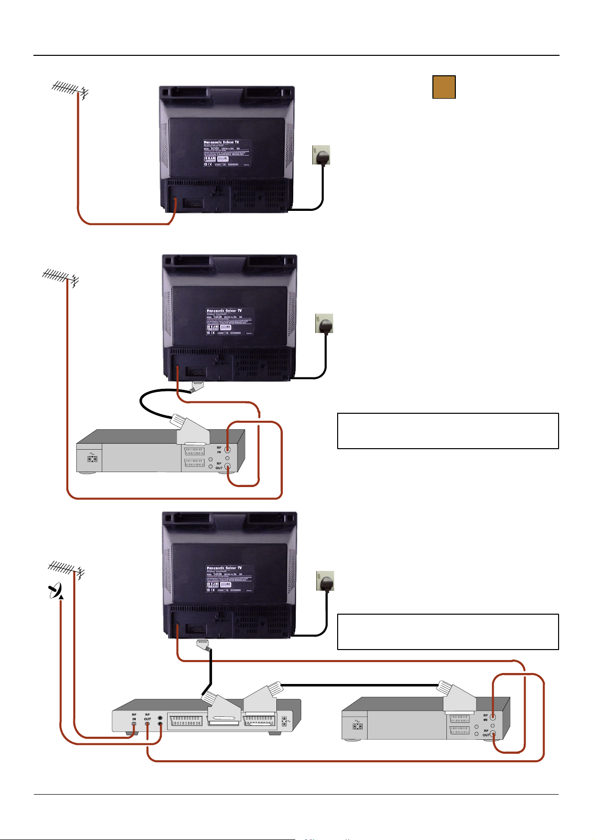
INSTALLATION AND SET---UP
1
Mains
Socket
Mains
Socket
TV only
Connect Aerial co--- axial cable direct to TV RF IN
socket.
OR
USING A VCR
Connect aerial co ---axial cable to RF Input socket of
VCR and a RF co--- axial cable from VCR RF Out
socket to TV RF IN socket.
The VCR can also be connected to the TV using a
SCART to SCART lead.
VCR
SATELLITE RECEIVER
Further details of Audio/ Video connections can
be found on page 12.
OR
USING A VCR AND SATELLITE RECEIVER
Connect aerial co ---axial cable to RF Input socket of
Satellite Receiver. An RF co---axial cable connects
from Satellite Receiver RF Out socket to VCR RF IN
socket.
Mains
Socket
A further co ---axial cable connects from the VCR RF
OUT socket to the TV RF IN socket.
The Satellite Receiver and VCR can also be linked
by SCART to SCART lead.
Further information for VCR and Satellite Rece iver
installation with this TV can be found on page 13.
VCR
Ancillary equipment and leads are not supplied.
5
Page 6

INSTALLATION AND SET---UP
2 3
Switch ON your VCR (if connected).
Switch ON your Satellite Receiver (if connected).
Plug the TV into a mains socket and switch ON.
Programmes will appear immediately if your
dealer has already tuned the TV for you.
If the TV has not been tuned for you then
Auto Tuning will begin. TV stations will be
located and stored.
CH21
Auto Tuning
21 69
4
IT IS IMPORTANT that you only use TV programme position ‘0’ to view your VCR. If your VCR picture does not appear on programme
position ‘0’ (the VCR position), it will be necessary to either adjust the RF channel of the VCR (refer to your VCR operating instructions) or
to adjust the tuning of the TV’s programme position ‘0’ or both until the RF output channel of the VCR is received, refer to page 13 for
guidance.
The first available channel will be displayed.
1
CH41
The TV stations will be stored in the order that they
have been found, if the order is not to your
preference it can be rearranged. Refer to the Tuning
menu Swap feature --- see page 9 for details.
Programme change
Volume adjust
6
Page 7

LOCATION OF CONTROLS
On Screen Displays
Menu Title
Cursor Bar
Sub Menu
Commands :
A guide to the various options available
when in On Screen Menu operations.
Front Panel Controls
Main Menu
Contrast
Brightness
Colour
Sharpness
C --- A --- T --- S
Tuning Menu
: Select
--- / + : A d j u s t
N:Exit
Mains Power On/Off switch
STR
Stores tuning and other function settings
F
Selects a function from :
Volume, Contrast, Brightness, Colour, Sharpness,
C--- A ---T ---S and Manual Tuning.
Remote Control keys
Standby On/Off
Adjusts currently selected
function. Adjusts the volume if
no function is selected
Function Select
Press to display the On Screen Menus
(Page 8)
Restores the levels previously set with STR
(TV front panel)
Headphone socket
RCA Audio/Video sockets
TV / AV
Switches between TV and AV modes
/ --- , /+
Programme up / down.
When a function is already displayed,
allows adjustment of the function.
Switches between TV and AV modes (Page 12)
Sound mute On/Off
Status : Displays programme position, channel
number and time
Channel up/down and Menu option select
Off timer
Press to select from 30, 60 or 90 minutes
Numeric keys for :
Programme change
Direct channel access
Direct channel access
Press and enter channel number using
numeric keys
Selection of programmes 10--- 60 using numeric
keys
7
Page 8

MENU OPERATION
Menu operation is to be used in conjunction with the On Screen Display commands to guide
you through function adjustments and tuning operations
Auto Tuning start
Select
Display Menu /
Previous Menu
Exit Menu
Main Menu
Contrast Colour
Brightness Sharpness
The Contrast, Brightness, Colour and Sharpness may be altered
to suit the viewing conditions and personal preferences.
Display Menu Select function and adjust
Main Menu
Contrast
F
Brightness
Colour
Sharpness
C --- A --- T --- S
Tuning Menu
Adjust/Access
Main Menu
Contrast
Brightness
Colour
Sharpness
C --- A --- T --- S
Tuning Menu
: Select
--- /+ : Adjust
N:Exit
C --- A --- T --- S : C o n t r a s t A u t o T r a c k i n g S y s t e m
Automatically adjusts the contrast setting to compensate for
any changes in the ambient lighting of the surroundings.
To obtain best results first set the Contrast to maximum, to
a l l o w a g r e a t e r op e r a t i n g ra n g e f o r C --- A --- T --- S , th e n se l e c t
one of the 3 settings as desired.
Display Menu Select C --- A---T---S and adjust
Main Menu
F
Contrast
Brightness
Colour
Sharpness
C --- A --- T --- S
Tuning Menu
: Select
--- /+ : Adjust
N:Exit
C --- A --- T --- S
C --- A --- T --- S
C --- A --- T --- S
Brightness
Medium Sensitivity
High Sensitivity
Main Menu
Contrast
Brightness
Colour
Sharpness
C --- A --- T --- S
Tuning Menu
C --- A --- T --- S
Off
8
Page 9

MENU OPERATION
Tuning Menu
The Tuning menu provides access to both manual and automatic
tuning menus.
Display Menu and select “Tuning Menu” Access “Tuning Menu”
F
Main Menu
Contrast
Brightness
Colour
Sharpness
C --- A --- T --- S
Tuning Menu
: Select
--- / + : A c c e s s
N:Exit
Auto Tuning
The Auto Tuning menu allows you to automatically retune the TV,
particularly useful if you move to an area that is served by a
different transmitter.
First access the Tuning menu as described above.
1
Access “Auto Tuning” Start
2
1
CH44
Tuning Menu
Auto Tuning
Manual Tuning
Shipping Condition
Swap
: Select
--- / + : A c c e s s
F : Previous Menu
N:Exit
3
1
CH44
Tuning Menu
Auto Tuning
Manual Tuning
Shipping Condition
Swap
: Select
--- / + : A c c e s s
F : Previous Menu
N:Exit
Confirm Start Ready to go
Auto Tuning
TV/AV : Yes
F : Previous Menu
N:Exit
Tuning data will be Erased !
Are you sure ?
4
1
CH44
Auto Tuning
TV/AV : Start
F : Previous Menu
N:Exit
Tuning data will be Erased !
9
Page 10

MENU OPERATION
p
rogram
mep
n
Shipping Condition start
Manual Tuning store
Adjust/Access
Manual Tuning search
Display Menu /
Previous Menu
Exit Menu
Manual Tuning
The Manual tuning menu allows individual programme positions
to be tuned manually.
First access the Tuning menu as described on Page 9.
Access “Manual Tuning”
Select
Manual Tuning programme select
1. Choose
2. Search for channel
3. Store
Repeat steps 1 to 3 as necessary to store
other channels
ositio
1
Tuning Menu
Auto Tuning
Manual Tuning
Shipping Condition
Swap
: Select
--- / + : A c c e s s
F : Previous Menu
N:Exit
Shipping Condition
Allows you to clear all tuning information and reset all control
levels back to the factory settings.
First access the Tuning menu as described on Page 9.
1 2
Access “Shipping Condition” Start
1
Tuning Menu
Auto Tuning
Manual Tuning
Shipping Condition
Swap
: Select
--- / + : A c c e s s
F : Previous Menu
N:Exit
1
Manual Tuning
: Programme Position
--- / + : S t a r t S e a r c h
TV/AV : Store
F : Previous Menu
N:Exit
21 69
Shipping Condition
TV/AV : Start
F : Previous Menu
N:Exit
Tuning data will be Erased !
10
Page 11

MENU OPERATION
r
A
r
Shipping Condition (Continued)
Confirm Start
Readyfo
utoTuningo
Manual Tuning.
43
Refer to Page 9 and 10.
1
Shipping Condition
TV/AV : Yes
F : Previous Menu
N:Exit
Tuning data will be Erased !
Are you sure ?
Swap
If the programme order after Auto Tuning is not to your
preference you can swap programmes between positions.
An example could be for regional variations, e.g. BBC1 Wales
and BBC1 West, where you may want to swap them so that
BBC1 West appears on programme position 1.
First access the Tuning menu as described on Page 9.
Access “Swap” Swap programmes
1
CH44
Tuning Menu
Auto Tuning
Manual Tuning
Shipping Condition
Swap
: Select
--- / + : A c c e s s
F : Previous Menu
N:Exit
Tuning Menu
Auto Tuning
Manual Tuning
Shipping Condition
Swap
: Select
--- / + : A c c e s s
F : Previous Menu
N:Exit
Swap
Position 01 CH44
with
Position 07 CH58
: Select
--- /+ : Adjust
TV/AV : Swap
F : Previous Menu
N:Exit
Manual Tuning (front panel of the television)
The stations may also be manually tuned using the controls on
the front of the television.
Press the F key (Front panel) until “Manual Tuning” is reached.
Press --- or + to access “Manual Tuning”.
Manual Tuning (Front Panel)
TV/AV : Programme Position
--- / + : S t a r t S e a r c h
STR : Store
F, N : E x i t
21 69
Store
Function select /
Exit
F
Change programme position
Search
11
Page 12

AUDIO / VIDEO CONNECTIONS (FRONT OR REAR)
AV (Audio / Video) is a dedicated input for VCR’s, Satellite Receivers and other Audio / Video equipment.
This TV is capable of switching to AV operation automatically if the equipment connected provides a switching signal to the SCART
socket.
In this condition the display will show EC and it is possible to change the programme position of the TV without changing the displayed
picture (This is not possible when using the front AV connections).
Input/Output from
Video input
to V socket
Audio input
to A socket
Output from
Headphone
socket
AV SCART Socket
SCART Cable
VCR
RCA
Video Cable
Audio Cable
VCR
CAMCORDER
RCA
Headphones
with 3.5mm
jack plug
SATELLITE RECEIVER
CAMCORDER
COMPUTER (RGB)
NOTE :
Ensure that the RGB
equipment is switched OFF
before returning to TV mode.
Ancillary equipment and cables shown are not supplied with this TV set.
Do not connect a computer with TTL output (5V) to this TV set.
The TV’s speaker will be automatically disconnected whilst the headphones are connected.
Do not connect front and rear AV inputs simultaneously, as the sound and pictures will be mixed.
12
Page 13

VCR I NSTALLATION
Your new TV is supplied with programme position ‘0’ designed specifically to receive an RF signal from a VCR.
However, depending on the VCR’s setting you may not receive any picture or sound from the VCR on programme position ‘0’ of the TV.It
will be necessary to either adjust the RF channel of the VCR or to adjust the tuning of the TV’s programme position ‘0’ or both until the RF
output channel of the VCR is received.
It is intended that this advice is used in conjunction with the instruction books for your ancillary equipment.
TO TUNE YOUR VCR TO THE TV
RF CHANNEL ADJUST
Insert
recorded tape
and select
playback
Set TV to
programme
position ‘0’
VCR
Adjust
tuning
TO TUNE YOUR TV TO THE VCR
Access the Manual tuning menu as
detailed on page 9.
Programme position and current
channel are displayed top left of screen
To select programme position ‘0’
--- + To start search for VCR playback
VCR
CH32
Manual Tuning
: Programme Position
--- /+ : St a rt Se ar c h
TV/AV : Store.
F : Previous Menu
N:Exit
21
69
rear of
VCR
Note :
Some VCR’s are capable of adjusting their
RF channel via their remote control unit.
VCR
To store position
To return to viewing screen
Operation
completed
See below for
installation of VCR
and
Satellite Receiver
If you are going to use a Satellite Receiver and a VCR, it is important, to avoid tuning problems, that they are both tuned to output their
signals on different channels. For example, if your VCR is tuned to output channel 32, your Satellite Receiver could be set to output
channel 34. Refer to your Satellite Receiver and VCR instruction books for precise tuning information.
13
Page 14

TROUBLE---SHOOTING
C
heck
Aerial
l
d
i
Before calling for service, determine the symptoms and make a few simple checks as shown below. For service please contact your local
Panasonic dealer quoting the model number and serial number (both are located at the rear of the TV).
Symptoms
Picture Sound
Snowy Picture
or
Multiple Images
Interference Noisy Sound Electrical appliances, vehicles, fluorescent lights
Normal Picture Noisy or No Sound Volume level or sound muted
No Picture No Sound
No Colour Normal Sound Colour controls set at minimum levels
Scrambled Normal or Weak Sound Retune channel(s)
GENERAL I NFORMATION
Noisy Sound
or
Normal Sound
s
ocation,
Not plugged into A.C. outlet, not switched on
picture / sound controls set at minimum levels
rection or connection
Sleep Feature
If the set is not switched off when the TV station stops transmitting , it will automatically go to standby mode after 30 minutes. This
function will not operate when in AV mode.
Last Position Memory
Certain functions have a last position memory, i.e. the setting at the time of switch off will be the setting used when the receiver is
switched on again:
Programme position Colour Volume
Contrast Brightness Standby
S h a r p n e s s S t a t u s C --- A --- T --- S
TV Games / Home Computers
Extended use of TV games or home computers with any television set can cause a permanent ‘shadow’ on the screen. This type of
irreversible picture tube damage can be limited by observing the following points :
D Reduce the brightness and contrast levels to a minimum viewing level.
D Do not operate the television set for a continuous period of time while using TV games or home computers.
This type of picture tube damage is not an operating defect and as such is not covered by the Panasonic warranty.
14
Page 15

SPECIFICATIONS
Model Number: TC--- 14JR1
Power Source: 220--- 240V 50Hz A.C.
Power Consumption: 33W
Standby Power Consumption: 1,1W
Picture Tube: 34cm visible diagonal
Audio Output (music) 6W , 8Ω impedance, mono
Dimensions: 352 (H) x 371 (W) x 371,5 (D) mm
Weight: 9,5 kg
Receiving Systems: PAL I UHF E21--- 69
PAL 525/60
Aerial (rear): UHF
Headphones (front): 3,5mm, 8Ω impedance, mono
A V --- R e a r : 21 pin terminal --- Audio/Video in/out, RGB in
A V --- F r o n t : RCA Audio in/RCA Video in
Design and specifications are subject to change without notice.
Weight and dimensions shown are approximate.
SCART TERMINAL INFORMATION
1. Audio out (R)
2. Audio in (R)
3. Audio out (L)
4. Ground
5. Ground
6. Audio in (L)
7. Blue in
8. Status CVBS
9. Ground
1 0 . --- ---
11. Green in
1 2 . --- ---
13. Ground
14. Ground
15. Red in
16. Status RGB
17. Ground
18. RGB Status ground
19. CVBS out (video)
20. CVBS in (video)
21. Socket ground
2468101214161820
13579111315171921
15
Page 16

2000CX
16
Panasonic (U.K.) Ltd
Willoughby Road,
Bracknell,
Berks.
RG12 8FP
 Loading...