

Panasonic TC-1471AR User Manual
Panasonic
Colour Television
Model Nos. TC-1480Z
TC-1471ZR
TC-1471AR
Operating Instructions
Please read these instructions completely before operating this set.
TQB620531
B
Dear Panasonic Customer
Welcome to the Panasonic family of customers.
We hope that you will have many years of enjoyment from your new colour television set.
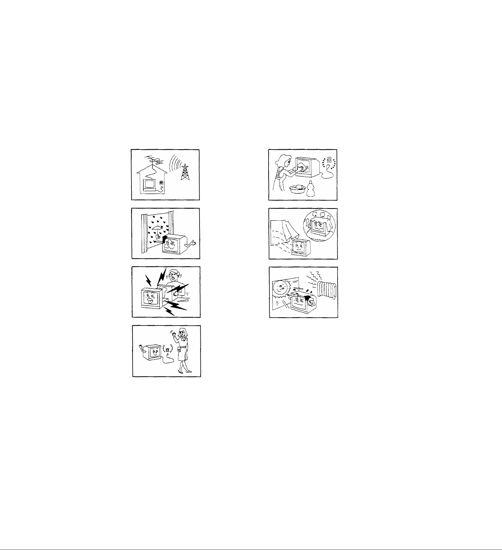
Warning and Cautions
Power Source and TV System
TC-1471AR:
This TV set can be operated
on AC 240 V, 50 Hz. It is de
signed exclusively for broad
cast systems PAL B & G.
TC-1480Z / 14712R:
AC 230 V, 50Hz.
To prevent damage which
may result in fire or electrical
shock, do not expose the TV
set to rain or excessive
moisture.
High Voltage :
Do not remove the rear
cover, as live parts are ac
cessible when it is removed.
Cabinet and Picture Tube Care
The cabinet and picture tube
can be kept in good condition
by simply wiping with a clean,
soft cloth moistened with mild
detergent and water. Do not
use solutions containing
benzol, petroleum or a chemi
cal cloth. For safety, turn the
TV set off when cleaning it.
Adequate ventilation is essen
tial to prevent failure of elec
trical components.
Avoid exposing the TV set to
direct sunlight and other
sources of heat.
Remove the plug from the
wait outlet { Power point )
when the TV set is not used
for a prolonged period of
time.
Contents
Location of controls.............................................................................................................................2
Operating Instructions ( Tuning Procedure ) ..................................................................................3-4
General Operation .............................................................................................................................5
Remote Control Operation { TC-1471AR/ZR only ) ...........................................................................6
Battery Replacement and Installation ( TC-1471AR/ZR only )
Troubleshooting .................................................................................................................................8
Specifications .....................................................................................................................................9
- 1 -
.........................................................
7
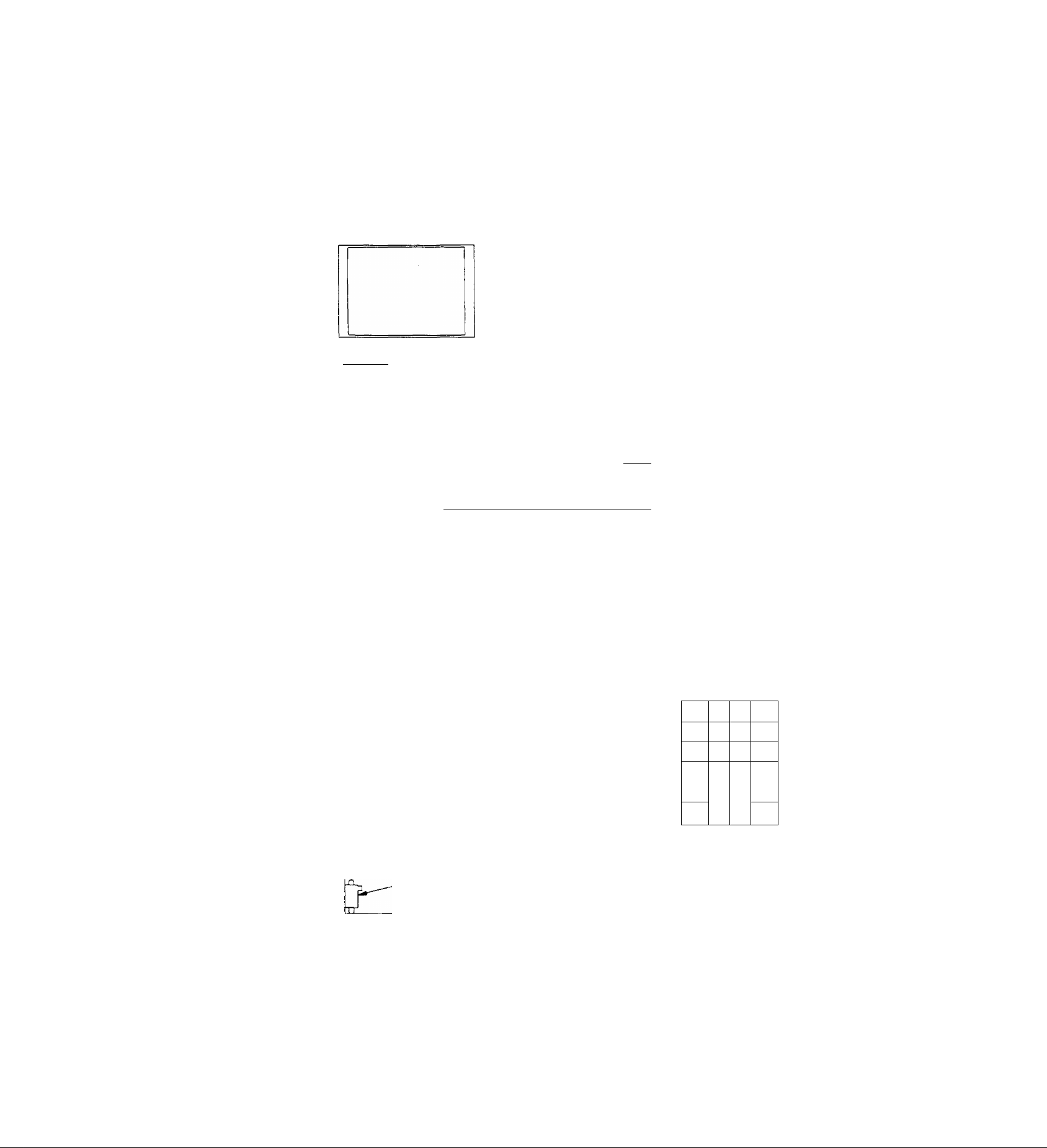
Location of Controls
( The numbers on this page are explained on pages 5 and 6.)
( Front View )
l""l I i~n[
^ Pull here to open
( Behind the door )
o
CE
Í
1
(7)
Remote Control Sensor
( Remote control model only )
O O
CD »
t f t
t
(5) (4)
(Front)
It
G) V A
ó
Sz
_____
I -njwia
—I ® @ @ (D
a)
~o
+
1
o
b)
SKP T RUT A PTE.
o ooo o
(6) Skip Tuning Preset (8)
button buttons button
( Remote Controt)
( Remote control model only )
Point the head towards
the remote control sensor.
F=i
(3) (2) (1)
( Rear View )
u
Cr
stand-by Power
indicator switch
( Remote control
model only )
Model Number
Aerial Terminal
Serial Number
JJ
2 -
(20)
(24) -
(28)(29)(25) -
(27)
(26)
1
2
- a
n
Á
0
- n
□
G t
7
- n
□
N
1 0
► n
□
□
*
□
□
3
□
□
6
5
□
6
□
1 I
□
n
-(21)
□ -
9
□
1 2
□
V
(22)
(23)
y
 Loading...