

Page 1
Before attempting to connect or operate this product,
please read these instructions carefully and save this manual for future use.
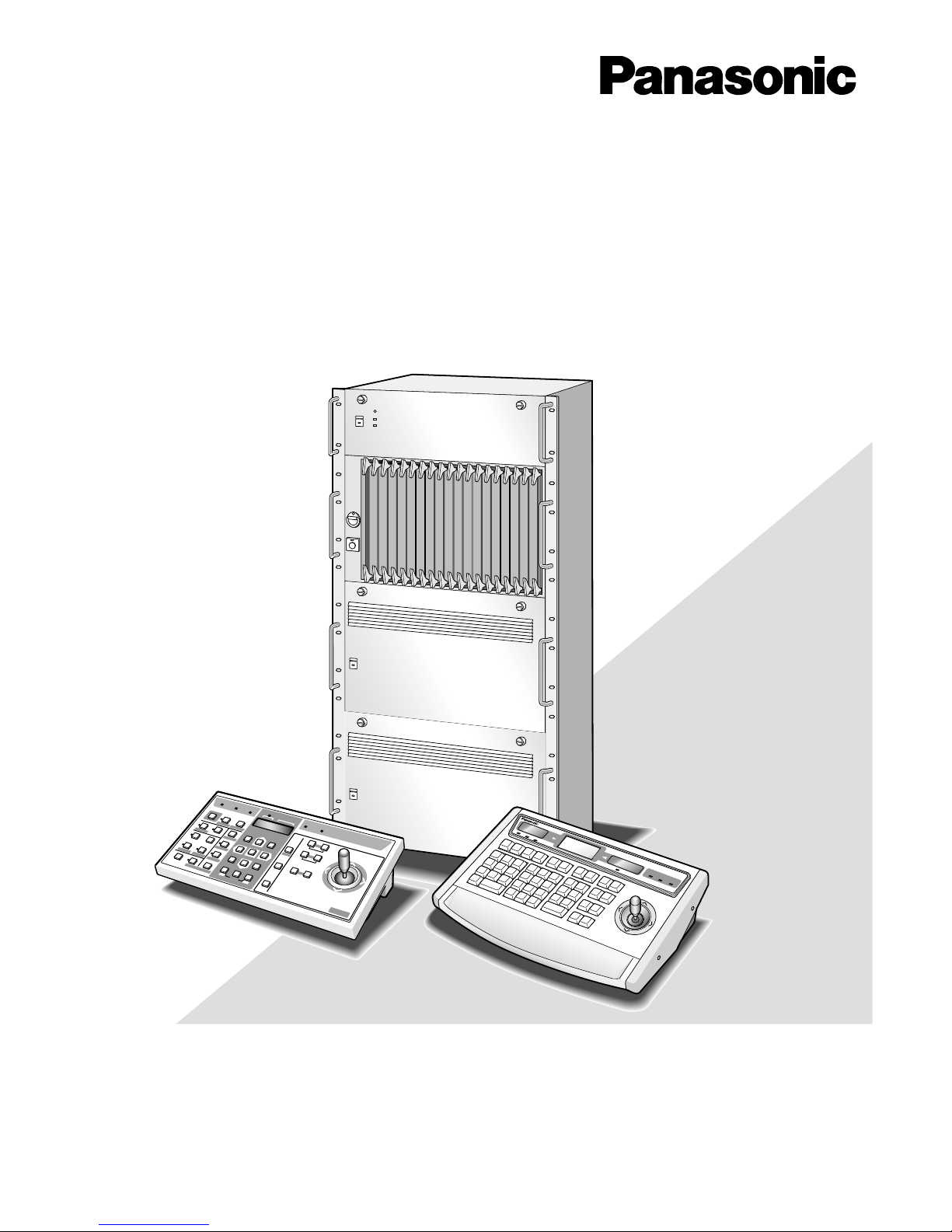
System 850 Matrix Switcher
Operating Instructions
System Controller WV-CU
850
Page 2
2
NOTE: This equipment has been tested and found to comply with the limits for a Class A digital device, pursuant to
Part 15 of the FCC Rules. These limits are designed to provide reasonable protection against harmful interference
when the equipment is operated in a commercial environment. This equipment generates, uses, and can radiate
radio frequency energy and, if not installed and used in
accordance with the instruction manual, may cause harmful
interference to radio communications.
Operation of this equipment in a residential area is likely to
cause harmful interference in which case the user will be
required to correct the interference at his own expense.
FCC Caution: To assure continued compliance, (example use only shielded interface cables when connecting to computer or peripheral devices). Any changes or modifications
not expressly approved by the party responsible for compliance could void the user’s authority to operate this equipment.
For U.S.A
WARNING:
To reduce the risk of fire or electric shock, do not expose this appliance to rain or moisture.
The lightning flash with arrowhead symbol, within an equilateral triangle, is
intended to alert the user to the presence of uninsulated "dangerous voltage"
within the product's enclosure that may
be of sufficient magnitude to constitute a
risk of electric shock to persons.
The exclamation point within an equilateral triangle is intended to alert the user
to the presence of important operating
and maintenance (servicing) instructions
in the literature accompanying the appliance.
CAUTION: TO REDUCE THE RISK OF ELECTRIC SHOCK,
DO NOT REMOVE COVER (OR BACK).
NO USER-SERVICEABLE PARTS INSIDE.
REFER SERVICING TO QUALIFIED SERVICE PERSONNEL.
CAUTION
RISK OF ELECTRIC SHOCK
DO NOT OPEN
SA 1965
SA 1966
Trademarks
• OS-9 is a registered trademark of Microware Systems Corporation.
• IBM is a trademark of International Business Machines Corporation.
• Intel and Pentium are trademarks of Intel Corporation.
• MS-DOS is a registered trademark of Microsoft Corporation in the U.S.A. and other countries.
• Windows is a trademark of Microsoft Corporation in the U.S.A. and other countries.
• VD2 is the original synchronization system of Matsushita Communication Industrial Co., Ltd. and Matsushita Electric Industrial Co.,
Ltd.
• Herb-OS is the original real-time operation system for the Matrix Switcher of Matsushita Communication Industrial Co., Ltd. and
Matsushita Electric Industrial Co., Ltd.
• Other company names and product names appearing in the manual are registered trademarks or trademarks of the company concerned.
Page 3

3
CONTENTS
PREFACE ................................................................................................................................................................................. 4
FEATURES ............................................................................................................................................................................... 4
PRECAUTIONS ........................................................................................................................................................................ 5
OUTLINE OF THE SYSTEM 850 MATRIX SWITCHER .............................................................................................................. 6
DETAILED PRODUCT DESCRIPTION ...................................................................................................................................... 9
WJ-SX850 Matrix Switcher Card Cage ............................................................................................................................... 10
WJ-PB85X08 Camera Input Board ..................................................................................................................................... 15
WJ-PB85D01 Character Board .......................................................................................................................................... 18
WJ-PB85Y08 Loop-Through Board .................................................................................................................................... 19
WJ-PB85R08 RS-485 Data Board....................................................................................................................................... 21
WJ-PB85C16 Crosspoint Input Board ................................................................................................................................ 24
WJ-PB85M16 Crosspoint Output Board ............................................................................................................................. 29
WJ-PB85T08 OSD (On-Screen Display) Board .................................................................................................................. 33
WJ-PB85A32 Alarm Input Board ........................................................................................................................................ 36
WJ-PB85L32 Alarm Output Board ...................................................................................................................................... 39
WJ-MPU850 Central Processing Unit ................................................................................................................................. 42
WJ-MPU855 Central Processing Unit ................................................................................................................................. 44
WJ-CA85L❑❑ Extension Cable .......................................................................................................................................... 46
WV-CU850 System Controller ............................................................................................................................................ 47
WV-CU350 System Controller ............................................................................................................................................ 52
INSTALLATIONS AND SYSTEM CONNECTIONS .................................................................................................................... 57
INSTALLATIONS ................................................................................................................................................................ 58
INSTALLATION OF SYSTEM COMPONENTS .................................................................................................................... 58
BOARD SELECTION FOR SYSTEM EXPANSION .............................................................................................................. 62
SYSTEM CONNECTIONS ................................................................................................................................................... 70
OPERATING PROCEDURE (with WV-CU850) ......................................................................................................................... 77
Log-in and Log-out ............................................................................................................................................................. 78
Monitor and Camera Selection ........................................................................................................................................... 79
Display Setting for Controller .............................................................................................................................................. 81
Controlling Camera Site Accessories ................................................................................................................................. 82
Camera Function Control ................................................................................................................................................... 85
Running Sequence ............................................................................................................................................................. 88
Monitor Display Control ...................................................................................................................................................... 90
Alarm Control ...................................................................................................................................................................... 95
Other Functions .................................................................................................................................................................. 97
OPERATING PROCEDURES (when a WV-CU350 is connected) ............................................................................................ 99
Log-in and Log-out ........................................................................................................................................................... 100
Monitor and Camera Selection ........................................................................................................................................... 102
Controlling Camera Site Accessories ................................................................................................................................. 104
Camera Function Control ................................................................................................................................................... 107
Running Sequence ............................................................................................................................................................. 110
Monitor Display Control ...................................................................................................................................................... 112
Alarm Control ...................................................................................................................................................................... 117
SPECIFICATIONS .................................................................................................................................................................... 119
SPECIFICATIONS ............................................................................................................................................................... 120
Page 4

4
FEATURES
PREF ACE
The Panasonic System 850 is a large-scale Matrix Switcher
System allowing control of up to 8 192 video inputs, 1 024
video outputs and 128 system controllers. It consists of
Main CPUs, Card Cages, Functional Boards, System
Controllers, Administration Console and other components.
The communication standard used is 10Base-T Ethernet,
which ensures system reliability and quick operation
response.
The System 850 is the ideal solution for applications requiring wide area coverage, reliability and system flexibility,
such as hotels, transportation facilities, stadiums, buildings
and so on.
The System 850 offers many features, the key feature being
its scale. It can support configurations of up to 8 192 video
inputs, 1 024 video outputs and 128 Ethernet system controllers. Moreover, its flexible, scalable and high-density
modular system architecture allows for easy expansion.
The System 850 is controlled and programmed via an
Ethernet or RS-485 port by standard, enhanced or highspeed CPUs. The standard CPU is designed for systems
having up to 512 inputs and 64 outputs, and the enhanced
CPU for systems having up to 1 024 inputs and 256 outputs. The high-speed CPU allows expansion of the system
from 1 024 inputs and 256 outputs to a maximum of 8 192
inputs and 1 024 outputs.
All of the components within this system are controlled via
an Ethernet (10Base-T) network allowing operators to perform the following operations.
• Logging in and out
• Switching camera video signals to monitors
• Controlling camera functions such as pan, tilt, zoom
and focus
• Setting and calling camera preset positions
• Activating pre-programmed group presets, tour and
group sequences
• Acknowledging and resetting alarms
Page 5

5
PRECAUTIONS
• Refer all work related to the installation of this product to qualified service personnel or system
installers.
• Do not block the ventilation opening or slots on the
cover.
To prevent the appliance from overheating, place it at
least 5 cm (2 inches) away from the wall.
• Do not drop metallic parts through slots.
This could permanently damage the appliance. Turn
the power off immediately and contact qualified service
personnel for service.
• Do not attempt to disassemble the appliance.
To prevent electric shock, do not remove screws or
covers.
There are no user-serviceable parts inside. Contact
qualified service personnel for maintenance.
• Handle the appliance with care.
Do not strike or shake, as this may damage the appliance.
• Do not expose the appliance to water or moisture,
nor try to operate it in wet areas.
Take immediate action if the appliance becomes wet.
Turn the power off and refer servicing to qualified service personnel. Moisture may damage the appliance
and also cause electric shock.
• Do not use strong or abrasive detergents when
cleaning the appliance body.
Use a dry cloth to clean the appliance when it is dirty.
When the dirt is hard to remove, use a mild detergent
and wipe gently.
• Do not operate the appliance beyond its specified
temperature, humidity or power source ratings.
Use the appliance at temperatures within –10°C +50°C (14°F - 122°F) and a humidity below 90%.
The input power source for these appliances is 120 V
AC 60 Hz.
Page 6
6
OUTLINE OF THE SYSTEM 850 MATRIX SWITCHER
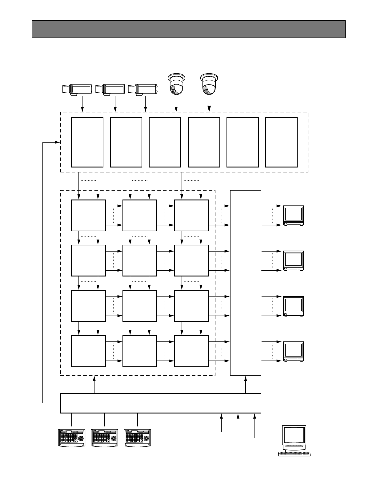
The diagram below shows an example of the System 850 Matrix Switcher controlling 768 inputs and 128 outputs.
641-768
128 ch
On-Screen
Display
MXOSD
Camera
Control
MXCONT 6
513-640
Camera
Control
MXCONT 5
385-512
Camera
Control
MXCONT 4
257-384
Camera
Control
MXCONT 3
129-256
Camera
Control
MXCONT 2
1-128
Camera
Control
MXCONT 1
Through OUT
256 IN
Cascadein32
OUT
Through OUT
256 IN
Cascadein32
OUT
Through OUT
256 IN
Cascadein32
OUT
Through OUT
256 IN
Cascadein32
OUT
C768
C513
Through OUT
256 IN
Cascadein32
OUT
Through OUT
256 IN
Cascadein32
OUT
Through OUT
256 IN
Cascadein32
OUT
Through OUT
256 IN
Cascadein32
OUT
C512 C257
M32
M1
M64
M33
M96
M65
M128
M97
M32
M1
M64
M33
M96
M65
M128
M97
4
3
32
Main CPU
2
1
ALARM
ACK
RESET
ALL
RESET
ARM
GROUP
PRESET
PREV
S-CTL IDOPE ID
NEXT
GROUP
SEQ
PAUSE STOP
TOUR
SEQ
REV
RUN
FWD
RUN
OSD
F.1 F.2 F.3
CMENU
OFF
F.4
CMENU
ON
F.5 F.6
CLOSE
IRIS
WIPER
OPEN
NEAR FAR
UP
BUSY
ACK
LOCK
CAMERA
INFORMATION
MONITOR
ALARM LINK OPERATE
DOWN
R
L
WIDE TELE
AUTO FOCUS
ZOOM
MONITOR
LOCK
LOGOUT
AUX1 OFF AUX1 ON
CALL
PRESET
PGM
PRESET
CAM
POSI
DIGITAL
OUT
CAMERA
(ENTER)
CAM ID GEN
(
ALARM
)
0
87
DEF OFF
AUTO PAN
DEF ON
MSTATUS
ALL
5964
231
SHIFT
CLEAR
(
ESC
)
System Controller WU–CU
850
BUSY
AREA
AUX2 OFF AUX2 ON
DEFAULT
FOCUS
ALARM
ACK
RESET
ALL
RESET
ARM
GROUP
PRESET
PREV
S-CTL IDOPE ID
NEXT
GROUP
SEQ
PAUSE STOP
TOUR
SEQ
REV
RUN
FWD
RUN
OSD
F.1 F.2 F.3
CMENU
OFF
F.4
CMENU
ON
F.5 F.6
CLOSE
IRIS
WIPER
OPEN
NEAR FAR
UP
BUSY
ACK
LOCK
CAMERA
INFORMATION
MONITOR
ALARM LINK OPERATE
DOWN
R
L
WIDE TELE
AUTO FOCUS
ZOOM
MONITOR
LOCK
LOGOUT
AUX1 OFF AUX1 ON
CALL
PRESET
PGM
PRESET
CAM
POSI
DIGITAL
OUT
CAMERA
(ENTER)
CAM ID GEN
(
ALARM
)
0
87
DEF OFF
AUTO PAN
DEF ON
MSTATUS
ALL
5964
231
SHIFT
CLEAR
(
ESC
)
System Controller WU–CU
850
BUSY
AREA
AUX2 OFF AUX2 ON
DEFAULT
FOCUS
ALARM
ACK
RESET
ALL
RESET
ARM
GROUP
PRESET
PREV
S-CTL IDOPE ID
NEXT
GROUP
SEQ
PAUSE STOP
TOUR
SEQ
REV
RUN
FWD
RUN
OSD
F.1 F.2 F.3
CMENU
OFF
F.4
CMENU
ON
F.5 F.6
CLOSE
IRIS
WIPER
OPEN
NEAR FAR
UP
BUSY
ACK
LOCK
CAMERA
INFORMATION
MONITOR
ALARM LINK OPERATE
DOWN
R
L
WIDE TELE
AUTO FOCUS
ZOOM
MONITOR
LOCK
LOGOUT
AUX1 OFF AUX1 ON
CALL
PRESET
PGM
PRESET
CAM
POSI
DIGITAL
OUT
CAMERA
(ENTER)
CAM ID GEN
(
ALARM
)
0
87
DEF OFF
AUTO PAN
DEF ON
MSTATUS
ALL
5964
231
SHIFT
CLEAR
(
ESC
)
System Controller WU–CU
850
BUSY
AREA
AUX2 OFF AUX2 ON
DEFAULT
FOCUS
Alarm Input
Serial/Parallel
Administration
Software (AD-GUI)
Camera Control Bay
MXSW 1-3
MXSW 2-3
MXSW 1-2
1
32
33
MXSW 3-3
65
64
MXSW 4-3
97
128
96
MXSW 2-2
MXSW 3-2
MXSW 4-2
MXSW 2-1
MXSW 3-1
MXSW 4-1
Through OUT
256 IN
Cascadein32
OUT
Through OUT
256 IN
Cascadein32
OUT
Through OUT
256 IN
Cascadein32
OUT
Through OUT
256 IN
Cascadein32
OUT
C256 C1
1
MXSW 1-1
Crosspoint Bay
Page 7

7
This manual uses the following abbreviations:
Component Description Abbreviation
Main Central Processing Unit ; MCPU
Local CPU Board ; LCPU
Camera Control Card cage ; MXCONT
Crosspoint Card cage ; MXSW
On-Screen Display Card cage ; MXOSD
Alarm Interface Card cage ; MXALM
Video Camera ; CAM or C
Video Monitor ; MON or M
Administration Console ; AD-GUI
The main components of the system are descried below.
● Camera Control Bay
The Camera Control Bay is a newly designed high-density combination unit which controls camera site and
video receiving.
A single camera control cage (MXCONT) allows for
flexible control of up to 128 cameras. A maximum of
8 192 cameras can be connected to several camera
control cages (MXCONTs).
The camera control cage (MXCONT) provides:
• 128-camera input in a Card Cage
• Control of external devices and cameras by means
of control data multiplexed on the video signal
• Display of camera title and clock using an installed
optional character board
• Detection of video input signal loss
● Crosspoint Bay
The Crosspoint Bay is a scalable distributed spacedivision switch. The basic card cage (MXSW) has a
maximum capacity of 256 inputs and 32 outputs.
Multiple MXSWs can be combined to support up to
8 192 inputs and 1 024 outputs.
The crosspoint cage (MXSW) features:
• 256-input and 32-output crosspoint switches in a
Card Cage
• Looped-through output
• 32-slave monitor input for cascade connection
• Ethernet interface for external control of crosspoint
switches
● On-Screen Display (OSD) Bay
The function of the On-Screen Display Bay is to display
the camera title, clock and system status on the active
monitors. The basic card cage (MXOSD) has a maximum of 128 video inputs and outputs. Multiple
MXOSDs can be combined to support up to 1 024
inputs and outputs.
The on-screen display cage (MXOSD) provides:
• A maximum of 128-monitor output in a Card Cage
• Display of monitor number, monitor status, camera
title and clock.
● Main CPU (Central Processing Unit)
The Main CPU controls the functions of the entire system. There are three types of CPUs, a Standard, an
Enhanced and a High-Speed (custom made configuration) CPU, each of which incorporates a high-performance Intel X86 processor running the OS-9 real-time
operating system. The Standard CPU supports up to
512 inputs and 64 outputs with 16 system controllers.
The Enhanced CPU is designed for a system size of
513 to 1 024 inputs and 65 to 256 outputs with 17 to 64
system controllers. The High-Speed CPU allows further expansion to up to 8 192 inputs and 1 024 outputs
with 128 system controllers.
The Main CPU provides:
• Central processing Board (CPU) and communication interface for controlling the entire system
• Ports for controlling the entire system, such as card
cages, system controllers and alarm interface
● Matrix Alarm Interface
The Matrix Alarm Interface is a scalable distributed digital input/output unit. Alarm input/output ports, each
with a specific functions, control the alarm processes.
The basic input/output element (MXALM) has a maximum capacity of 512 digital inputs or 512 digital outputs. Capacity can be expanded up to 1 024
inputs/outputs by combining two units.
● Administration Console
Administration Console is a GUI software that performs
system setup in a Window PC.
The PC is linked with main CPU via Ethernet. The system features can be programmed using Administration
Console.
● System Controllers
A system controller is a device used by an operator to
control specific components. There are two types of
system controllers, the RS-485 type corresponding to
an RS-485 and the Ethernet type to an Ethernet interface. A maximum of 128 system controllers can be
installed to control and operate the system.
Page 8
9
DETAILED PRODUCT
DESCRIPTION
Page 9
10
DETAILED PRODUCT DESCRIPTION
WJ-SX850 Matrix Switcher Card Cage
■ Preface
The WJ-SX850 is a card cage designed to allow flexible system expansion of the System 850 Matrix Switcher.
It is provided with a power supply for the boards installed, and a Local CPU board to control boards in the cage.
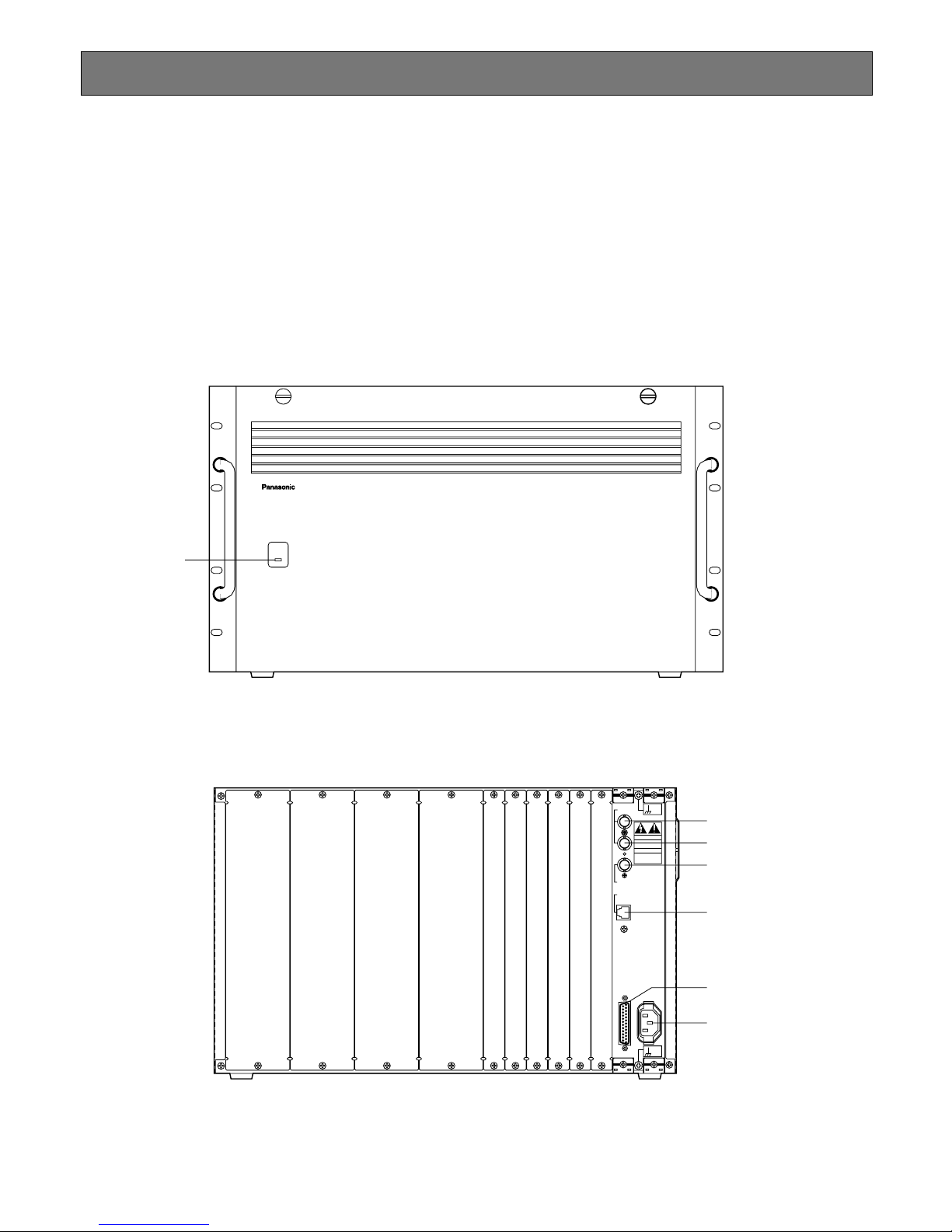
■ Appearance
DO NOT OPEN
RISK OF ELECTRIC SHOCK.
SIGNAL
GND
SIGNAL
GND
RS-232C
CAUTION
ATTENTION
NE PAS OUVRIR
RISQUE DE CHOCS
ELECTROUES
VS / VD
IN
OUT
VD OUT
ETHERNET
AC IN
850
u
y
t
r
e
w
● Rear View
OPERATE
Matrix Switcher WJ-SX
850
q
● Front View
Page 10
11
q Operate Indicator (OPERATE)
Is on when the power of the WJ-SX850 Matrix Switcher
Card Cage is turned on.
Note: The power switch of this cage is located under-
neath the front panel.
Remove the front panel by removing two screws on
the panel.
w VS/VD Input Connector (VS/VD IN)
Accepts either the VD (Vertical Drive) pulse or the VS
(Video Sync) signal for synchronizing the system.
Notes:
• This input is looped through to the VS/VD Output
Connector.
• When the VD (or VS) signal is supplied to the VS/VD
Input Connector, turn the VS/VD selection switch
(SW7) on the circuit board to the VD (or VS) position. The factory default setting of the VS/VD selection switch (SW7) is VD. Ask qualified service personnel about setting up this switch.
• The external sync signal should meet EIA RS-170
specifications and should not contain any jitters,
such as a VCR playback signal.
e VS/VD Output Connector (VS/VD OUT)
Outputs either the VD (Vertical Drive) pulse or the VS
(Video Sync) signal for synchronizing other system
components.
Note: The input at the VS/VD Input Connector is looped
through to this output. These inputs and outputs are
connected internally.
r VD Output Connector (VD OUT)
Outputs VD (Vertical Drive) pulses for synchronizing
other system components.
Notes:
• The internal VD pulse or the looped-through external VD pulse is provided at this connector.
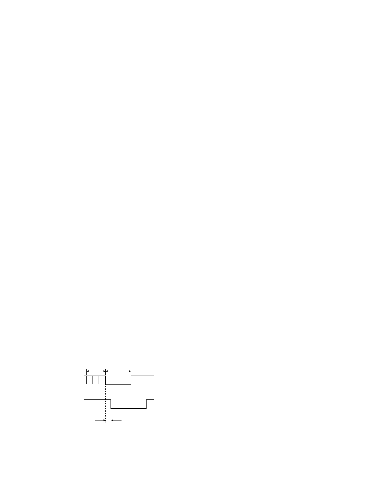
• When the VS signal is supplied to the VS/VD Input
Connector, the VD output signal from the VD Output
Connector will be delayed by approximately 15 µs
with respect to the V-sync of the VS input signal.
t Ethernet Port (ETHERNET)
For exchanging control data with the Central
Processing Unit (CPU) via Ethernet.
y RS-232C Port (RS-232C)
This port is used only for factory tests.
u AC Inlet Socket (AC IN)
Plug the power cord (supplied as a standard accessory) into this socket and connect the cord to an AC outlet.
VS input signal
VD output signal
approx. 15 µsec
3H V
Page 11
12
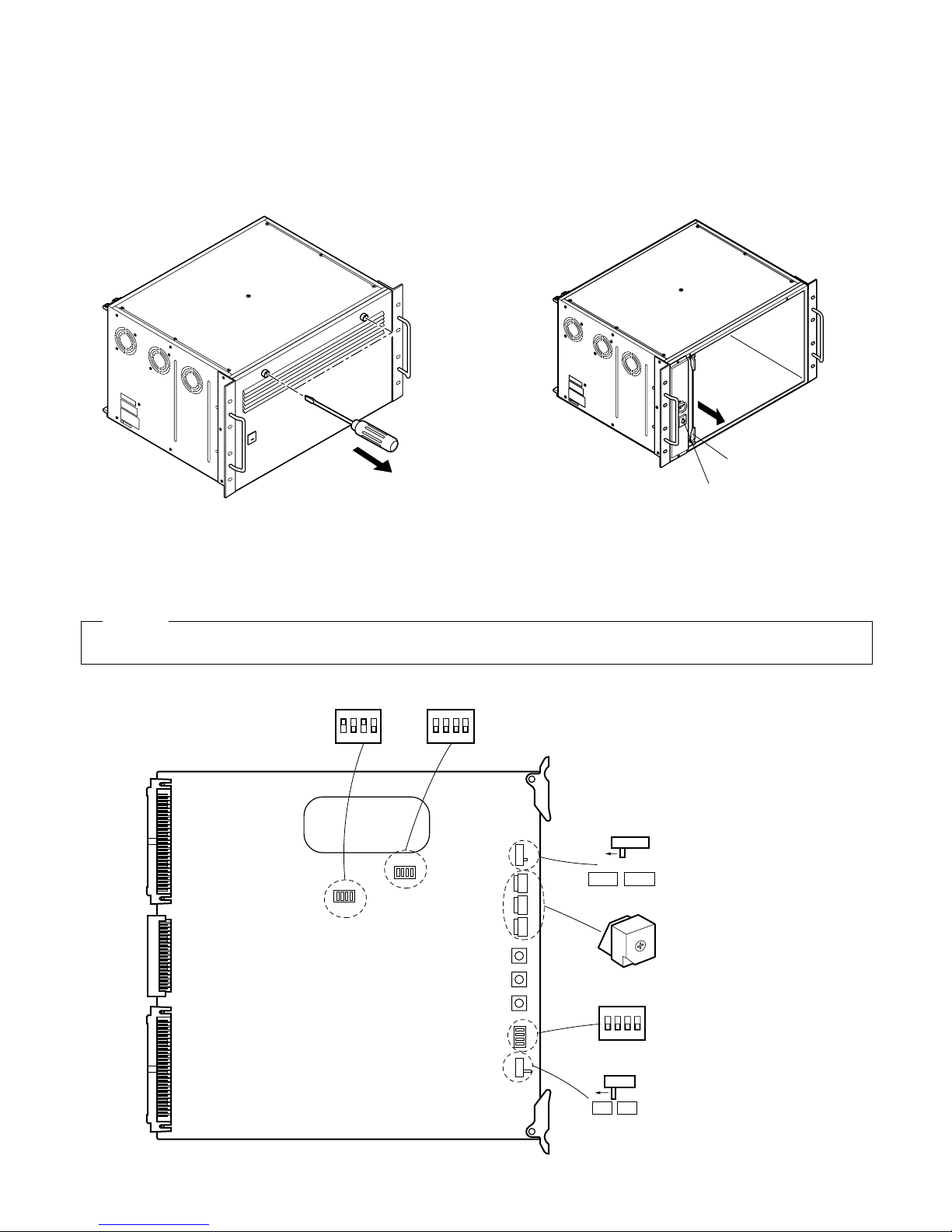
■ Board Setting
The following settings should be made by qualified service personnel or system installers.
1. Remove the front panel by removing two screws on the
panel.
Power Switch
Card Puller
2. Extract the Local CPU board by raising up the card
puller.
1234
ON
1234
ON
SW8
SW4
1234
ON
SW13
SW7
SW7
VD VS
SW11SW12SW10SW9
SW11
SH-F
E2P
CPU BOARD
0
1
2
3
4
5
6
7
8
9
A
B
C
D
E
F
SW1SW3SW2
Hold this board only by its edges. Otherwise components on the board may be damaged by static electricity.
Caution
SW1: Factory use only
SW3: LCPU Reset Switch
SW2: Card Cage Reset Switch
Page 12
13
Cage No.
1
2
3
4
5
6
7
8
9
10
11
12
13
14
15
SW Setting
SW12
0
0
0
0
0
0
0
0
0
0
0
0
0
0
0
0
0
0
0
0
0
0
0
1
1
1
1
2
2
2
1
2
3
4
5
6
7
8
1
2
3
4
1
2
3
SW10 SW9
Cage No.
16
17
18
19
20
21
22
23
24
25
26
27
28
29
30
SW Setting
SW12
0
0
0
0
0
0
0
0
0
0
0
0
0
0
0
2
3
3
3
3
4
4
4
4
5
5
5
5
6
6
4
1
2
3
4
1
2
3
4
1
2
3
4
1
2
31
32
33
34
35
36
37
38
39
40
41
42
43
44
1
1
1
1
1
1
1
1
1
1
1
1
1
1
6
6
7
7
7
7
8
8
8
8
9
9
9
9
3
4
1
2
3
4
1
2
3
4
1
2
3
4
SW10 SW9
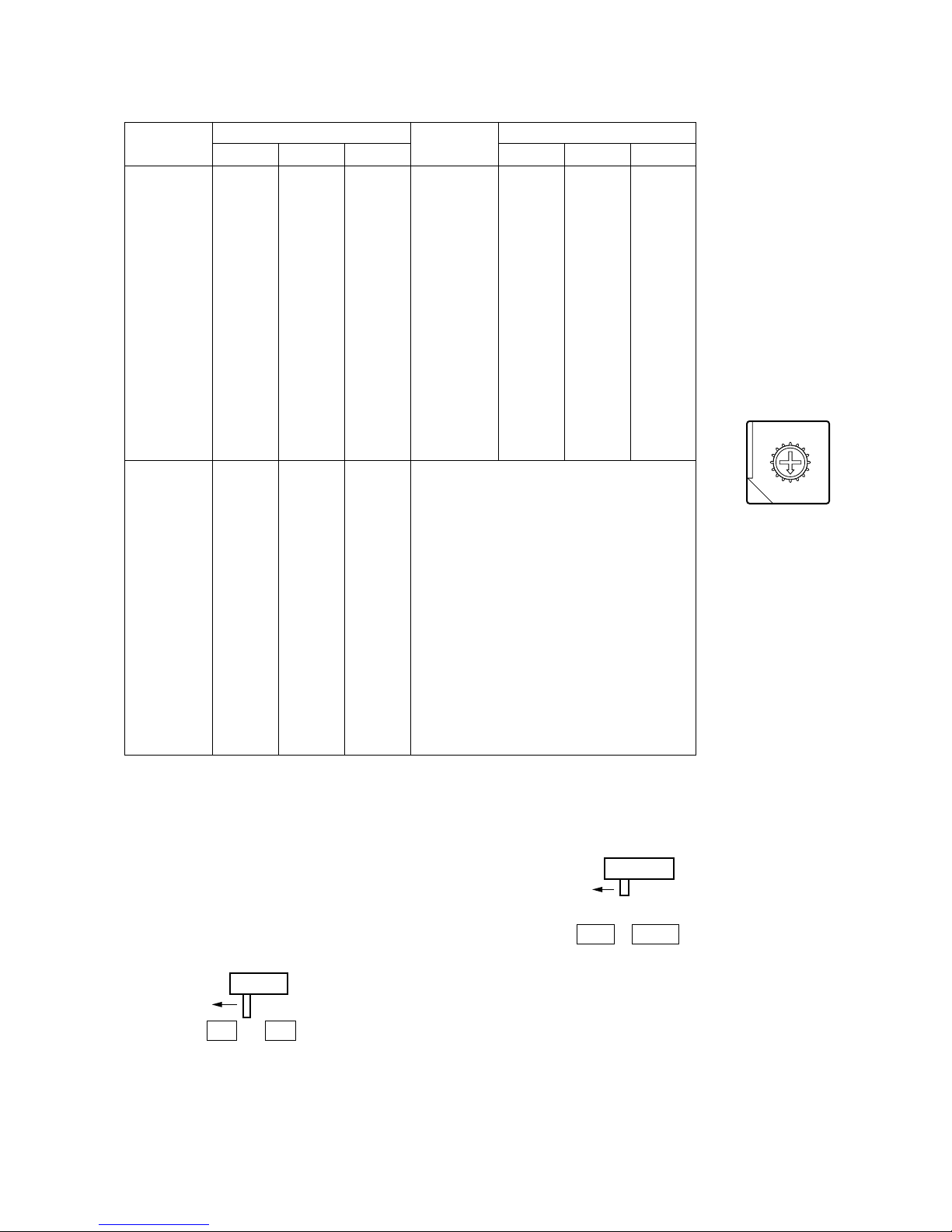
Designate further cage numbers, referring to the above
address table.
Cage numbers are available up to 1 024.
4. Set switch (SW7) on the board to select either VD or VS
for the Sync input signal, if applicable. The factory
default setting is VD.
SW7
VSVD
5. Confirm that switch (SW11) on the board is set to E2P
position.
SW11
SH-FE2P
8
9
A
B
C
D
E
F
0
1
2
3
4
5
6
7
3. Set switches (SW9, SW10 and SW12) on the board to designate the cage number as shown below.
The cage number and corresponding switch settings are given in the following address table.
The factory default setting is 000.
Page 13
14
Switch
Number
SW4
SW8
SW13
Setting Positions
1
ON
ON
OFF
OFF
ON
OFF
ON
ON
OFF
OFF
ON
OFF
234
7. Place the board into the CPU slot in the front of the
cage by sliding it along the board guide.
DIP SW8
1
4
OFF ON
PROM Mode
MAC Address
Write-enable
Mode
Normal Mode
Normal Mode
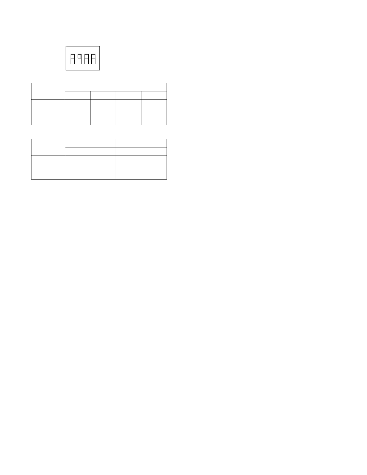
6. Confirm that switches (SW4, SW8 and SW13) on the
board are set as follows:
1234
ON
Page 14
15
WJ-PB85X08 Camera Input Board
■ Preface
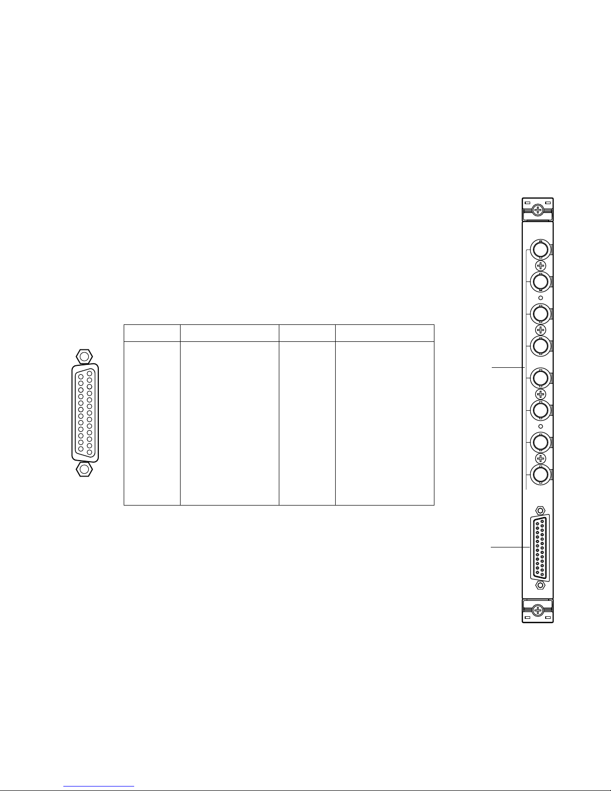
The WJ-PB85X08 Camera Input Board is an optional board for expanding the camera input capability of the System 850 Matrix
Switcher.
■ Appearance
Pin No. Designation
25
24
23
22
21
20
19
18
17
16
15
14
CAMERA 1
CAMERA 2
CAMERA 3
CAMERA 4
CAMERA 5
CAMERA 6
CAMERA 7
CAMERA 8
Not used
Not used
Not used
Not used
Pin No. Designation
13
12
11
10
9
8
7
6
5
4
3
2
1
Ground
Ground
Ground
Ground
Ground
Ground
Ground
Ground
Ground
Ground
Ground
Ground
Ground
q Camera Input Connector (CAMERA IN, 1 - 8)
These connectors accept either a color or B/W composite video signal from a camera.
In addition, the VD2 signal for synchronizing the vertical timing of the cameras, and data to
control camera site devices are multiplexed through this connector.
w Video Output Port (VIDEO OUT)
The video signal connected to the Camera Input Connector (CAMERA IN) is present at this
port.
The camera control data multiplexed on the video signal is not available at this port. When
the power of the Matrix Switcher Card cage is turned off, no signal is present at this port.
Connect between this output port and the VIDEO IN Port on the WJ-PB85C16 Crosspoint
Input Board of the Crosspoint Cage (MXSW) for switching camera input.
1
2
3
4
5
6
7
8
CAMERA IN
VIDEO OUT
CAMERA
q
w
17
16
15
14
5
4
3
2
1
20
19
18
8
6
23
22
21
11
10
9
7
25
24
13
12
Page 15
16
SW1
SW1
SW5SW4SW2
CN5
CN4
CANERA CNT
CN 101
CN 103
CN 102
CN 201
CN 203
CN 202
CN 301
CN 303
CN 302
CN 401
CN 403
CN 402
CN 501
CN 503
CN 502
CN 601
CN 603
CN 602
CN 701
CN 703
CN 702
CN 801
CN 803
CN 802
OFF
1234
0
1
2
3
4
5
6
7
8
9
A
B
C
D
E
F
Reset Switch
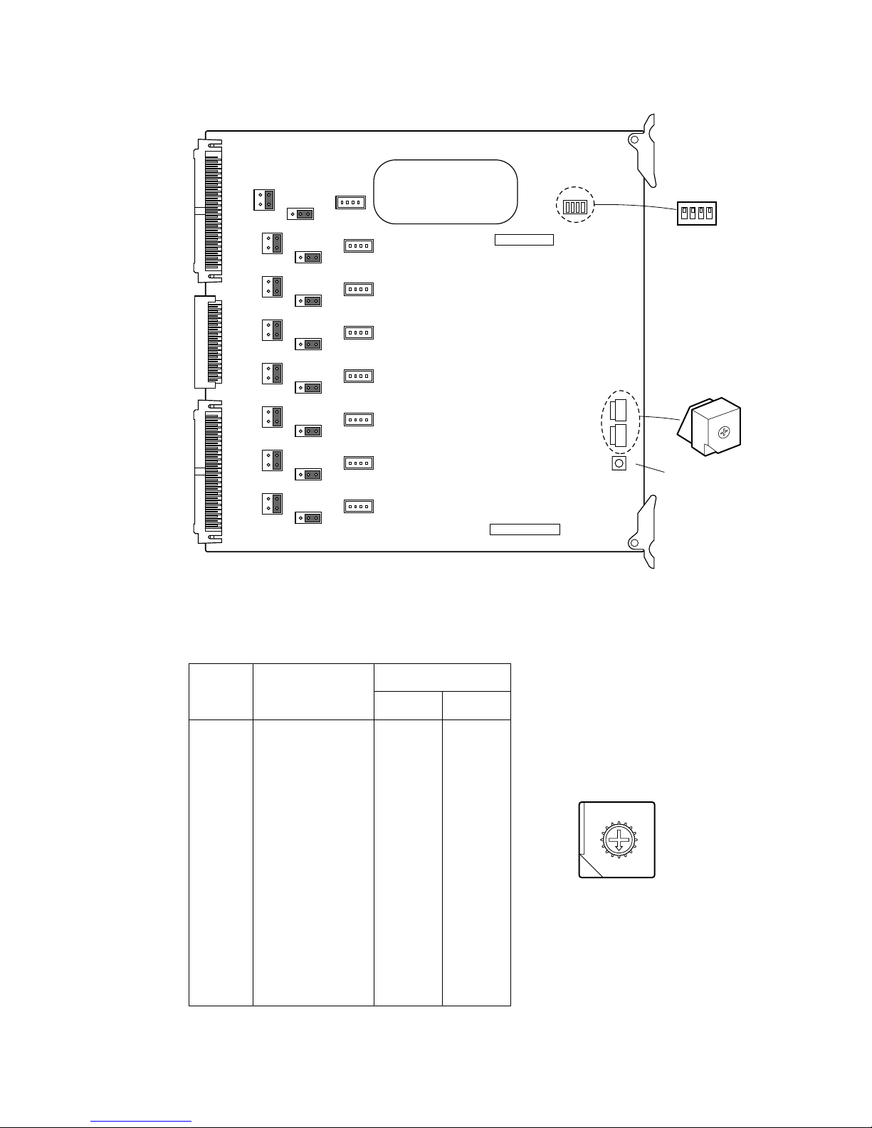
1. Set switches (SW4 and SW5) on the board to designate the camera input board number as shown in the following table.
The factory default setting is Board Number 1 (00)
Board
No.
Camera Input
SW Positions
SW5 SW4
1
2
3
4
5
6
7
8
9
10
11
12
13
14
15
16
0
0
0
0
0
0
0
0
0
0
0
0
0
0
0
0
0
1
2
3
4
5
6
7
8
9
A
B
C
D
E
F
1 - 8
9 - 16
17 - 24
25 - 32
33 - 40
41 - 48
49 - 56
57 - 64
65 - 72
73 - 80
81 - 88
89 - 96
97 - 104
105 - 112
113 - 120
121 - 128
8
9
A
B
C
D
E
F
0
1
2
3
4
5
6
7
■ Board Setting
Before installing this board, the following settings should be made by qualified service personnel or system installers.
Page 16
17
DIP
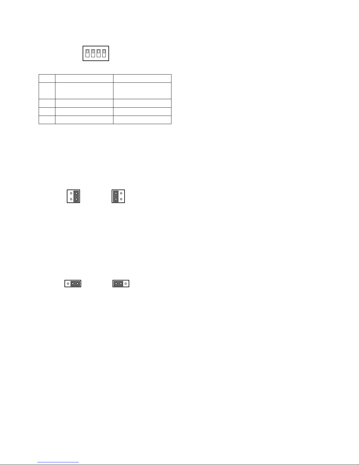
2. Confirm that switches (SW1) on the board are set to the
OFF position as shown below.
SW1
OFF
1234
3. Position jumper connectors (CN101, CN201, CN301,
CN401, CN501, CN601, CN701, and CN801) on the
board as shown below.
The factory default setting is positions 3 and 4
(Multiplexed Camera).
4. If the Character Board is installed on the Camera Input
Board, position jumper connectors (CN103, CN203,
CN303, CN403, CN503, CN603, CN703, and CN803)
on the board as shown below.
The factory default setting is positions 1 and 2.
CN101
13
24
CN101
Multiplexed Camera
Default Setting
Others
13
24
CN103
31
CN103
Default Setting Installed
Character Board
13
ON
1
Character display
without camera input
2 No retry mode
3 Reserved
4 Reserved (P)
OFF
No display
without camera input
3 retries mode
Reserved
Reserved (N)
Page 17
18
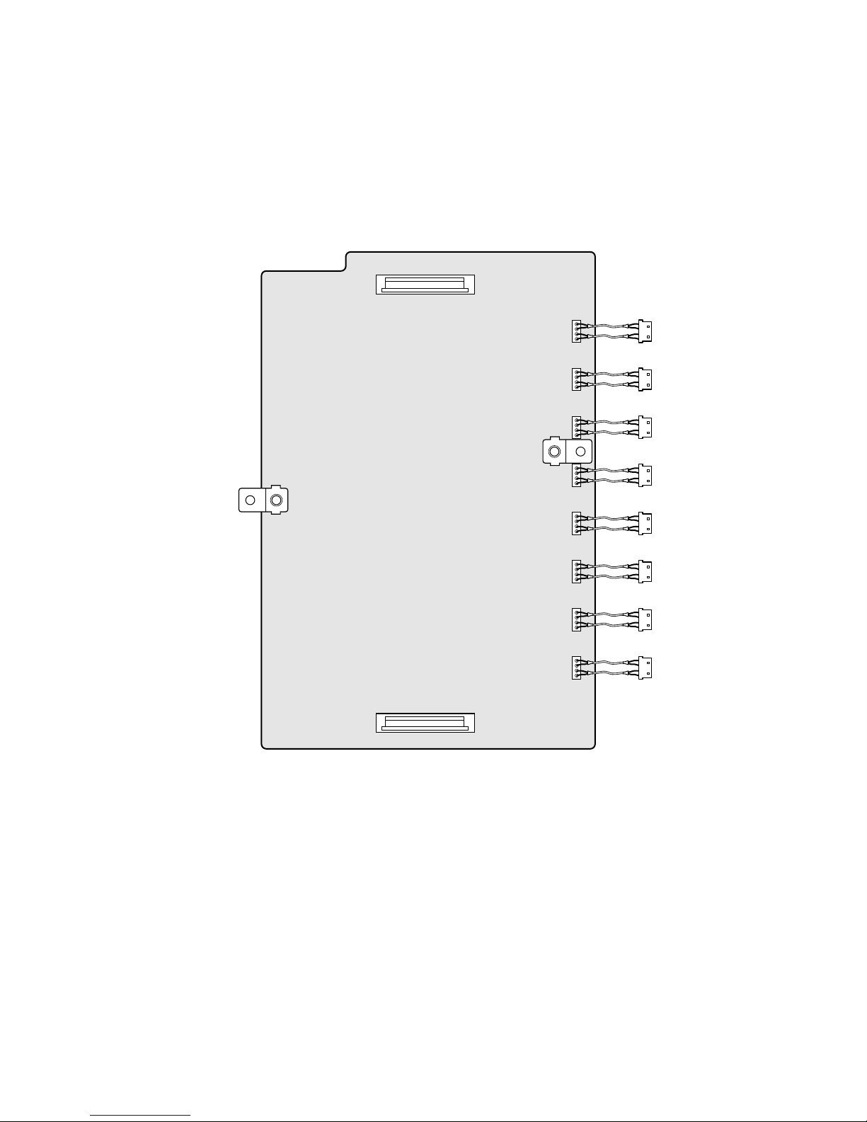
WJ-PB85D01 Character Board
■ Preface
The WJ-PB85D01 Character Board is an optional board installed on the WJ-PB85X08 Camera Input Board to enable display of
the time and date and camera number through the Video Output Port on the Camera Input Board.
■ Appearance
CN2
CN1
Page 18
19
WJ-PB85Y08 Loop-Through Board
■ Preface
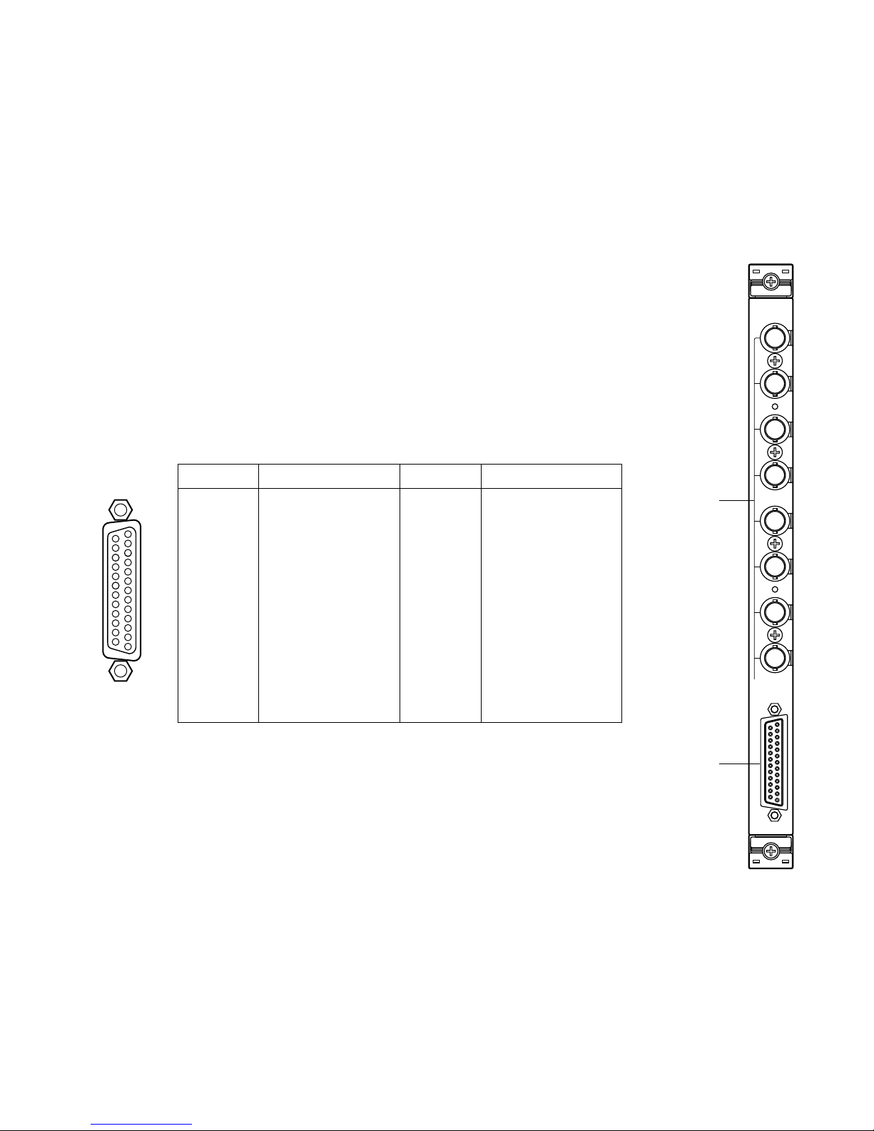
The WJ-PB85Y08 Loop-Through Board is an optional board used to exchange the BNC video input/output for the D-Sub video
output/input in order to expand the capabilities of the System 850 Matrix Switcher.
■ Appearance
q Through I/O Connectors (IN / OUT, 1 - 8)
These connectors accept the composite video output from the associated video equipment,
or provide the looped through video outputs connected to the Through I/O Port.
w Through I/O Port (IN / OUT)
This port accepts the composite video output from the associated video equipment, or provides the looped through video outputs connected to the Through I/O Connectors.
1
2
3
4
5
6
7
8
IN/OUT
IN/OUT
THRU
q
w
17
16
15
14
5
4
3
2
1
20
19
18
8
6
23
22
21
11
10
9
7
25
24
13
12
Pin No. Designation
25
24
23
22
21
20
19
18
17
16
15
14
VIDEO 1
VIDEO 2
VIDEO 3
VIDEO 4
VIDEO 5
VIDEO 6
VIDEO 7
VIDEO 8
Not used
Not used
Not used
Not used
Pin No. Designation
13
12
11
10
9
8
7
6
5
4
3
2
1
Ground
Ground
Ground
Ground
Ground
Ground
Ground
Ground
Ground
Ground
Ground
Ground
Ground
Page 19
20
CN801
1
2
CN601CN401CN201
CN701CN501
CN301CN101
CN801
■ Board Setting
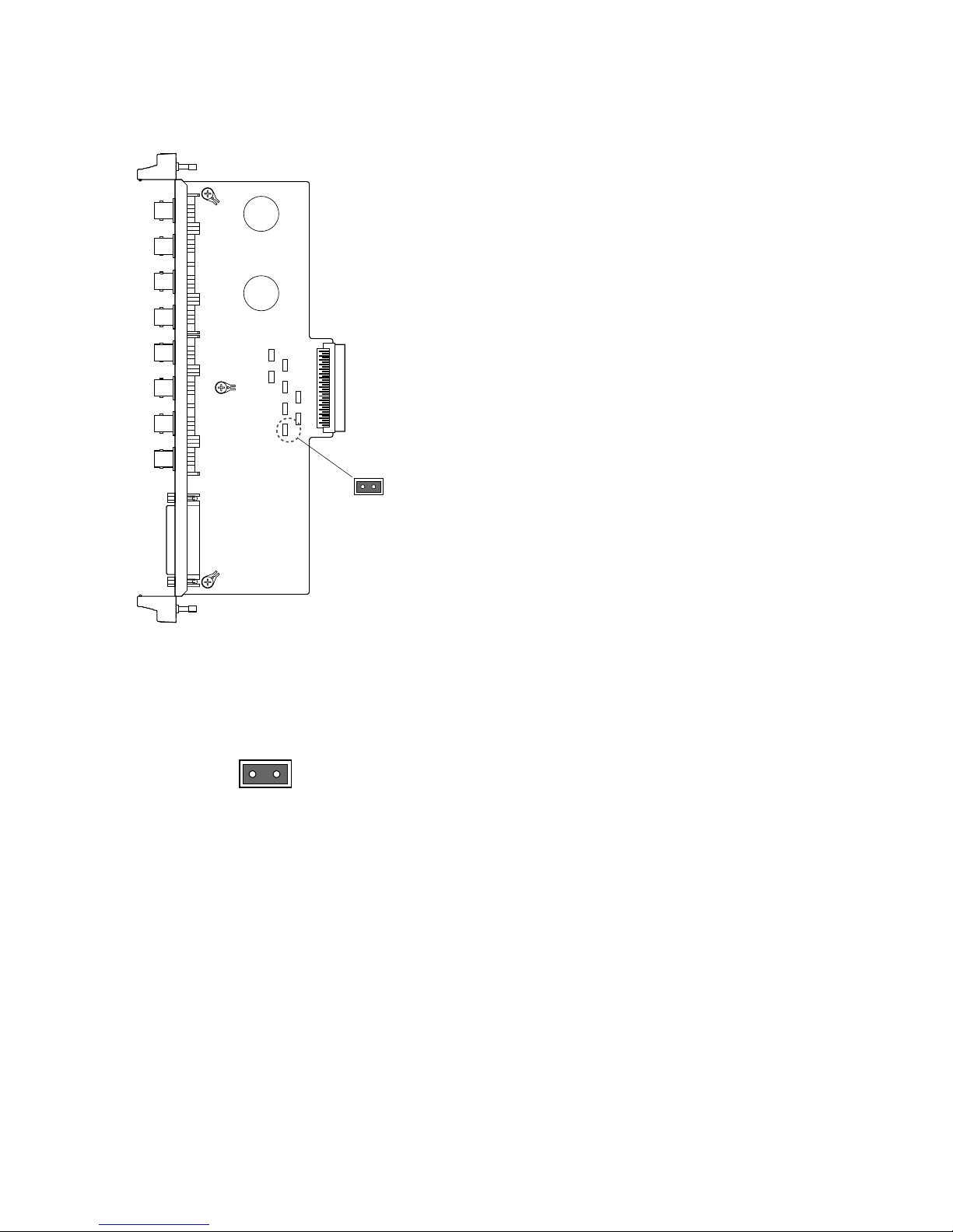
Before installing this board, the following settings should be
made by qualified service personnel or system installers.
1. Confirm that jumper connectors (CN101, CN201,
CN301, CN401, CN501, CN601, CN701, and CN801)
on the board are positioned as shown below.
CN101
12
Page 20
21
WJ-PB85R08 RS-485 Data Board
■ Preface
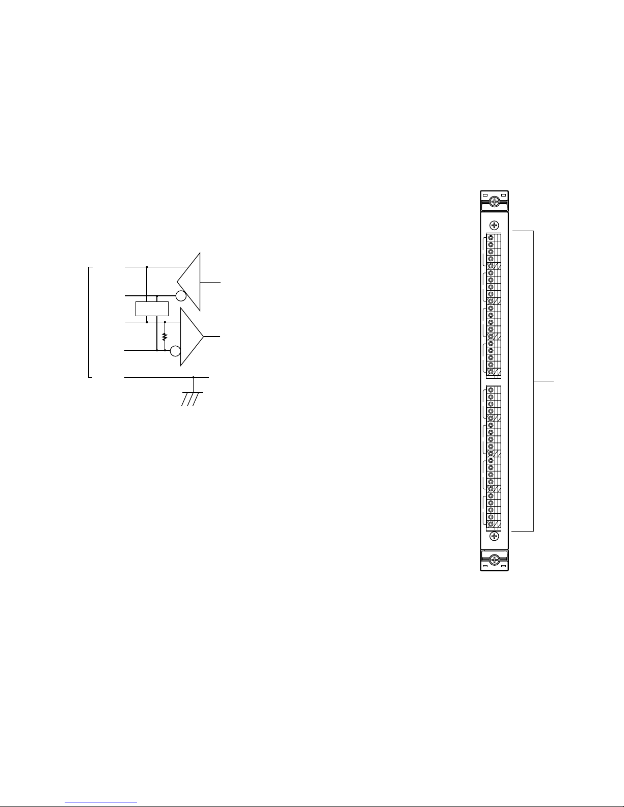
The WJ-PB85R08 RS-485 Data Board is an optional board for exchange of control data between the Camera Control Cage
(MXCONT) and the camera site.
■ Appearance
TXD
TB
RA (+)
RB
GND
RXDRT
TA (+)
S W
1
RT: Termination Resistor
SW: Selection Switch, Full Duplex/ Half Duplex
GND: Ground; Connected to each channel and
common ground.
q Data Connectors (TA/TB/RA/RB/G 1 - 8)
These connectors are used to exchange control data with the camera site devices. For connection, use a data grade shielded 4-wire twisted pair cable suitable for RS-485 communication.
q
RS485
A
T
B
A
R
B
G
A
T
B
A
R
B
G
A
T
B
A
R
B
G
A
T
B
A
R
B
G
1
2
3
4
A
T
B
A
R
B
G
A
T
B
A
R
B
G
A
T
B
A
R
B
G
A
T
B
A
R
B
G
5
6
7
8
Page 21
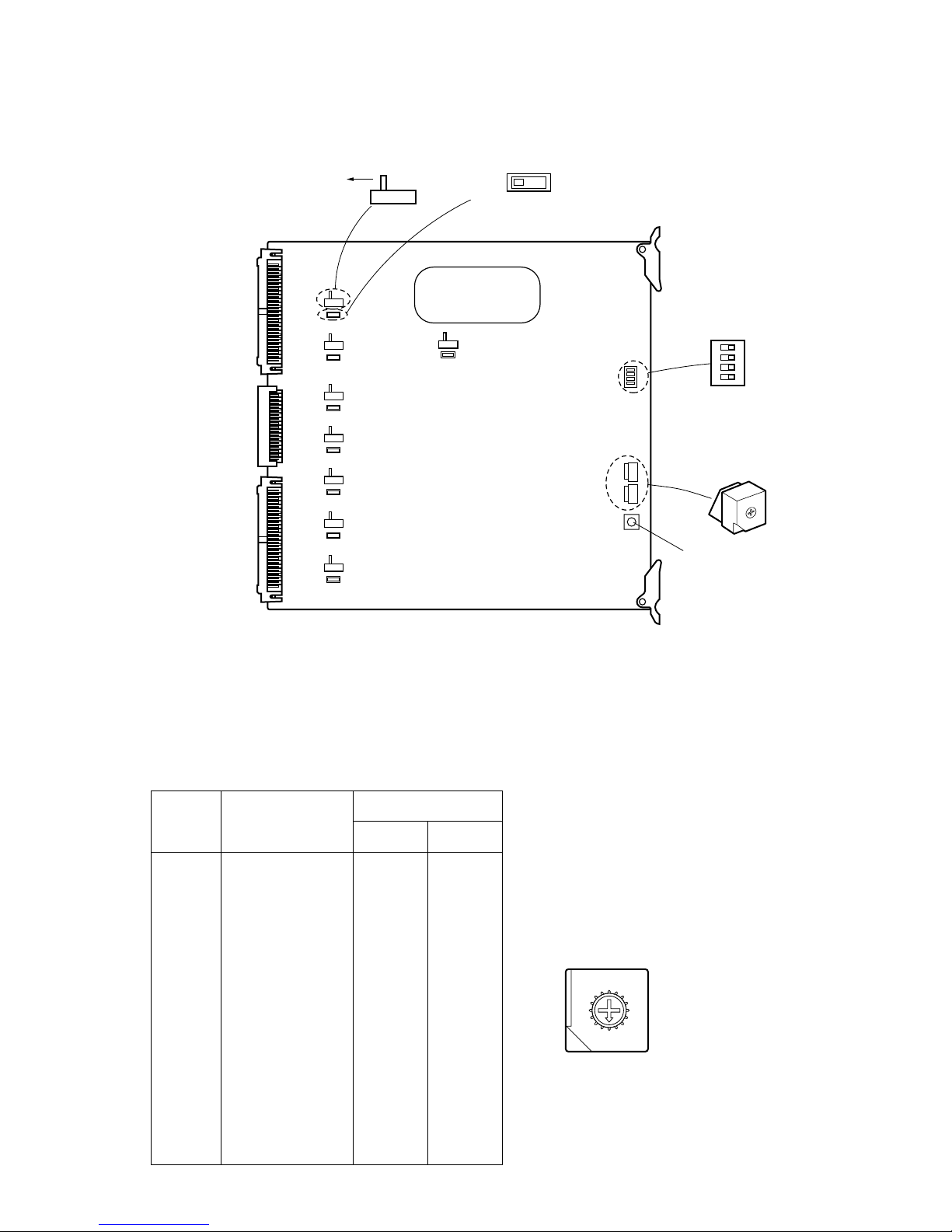
22
■ Board Setting
Before installing this board, the following settings should be made by qualified service personnel or system installers.
1234
OFF
SW3
SW2SW1SW4
RS-485 DATA BOARD
0
1
2
3
4
5
6
7
8
9
A
B
C
D
E
F
SW102
SW101
SW302
SW301
SW202
SW201
SW402
SW401
SW502
SW501
SW602
SW601
SW702
SW701
SW802
SW801
4LINE 2LINE
TERM
ON
TERM
OFF
Reset Switch
Board
No.
Data I/O
SW Positions
SW2 SW1
1
2
3
4
5
6
7
8
9
10
11
12
13
14
15
16
0
0
0
0
0
0
0
0
0
0
0
0
0
0
0
0
0
1
2
3
4
5
6
7
8
9
A
B
C
D
E
F
1 - 8
9 - 16
17 - 24
25 - 32
33 - 40
41 - 48
49 - 56
57 - 64
65 - 72
73 - 80
81 - 88
89 - 96
97 - 104
105 - 112
113 - 120
121 - 128
1. Set switches (SW1 and SW2) on the board to designate the RS-485 data board number as shown in the following table.
The factory default setting is Board Number 1 (00).
8
9
A
B
C
D
E
F
0
1
2
3
4
5
6
7
Page 22
23
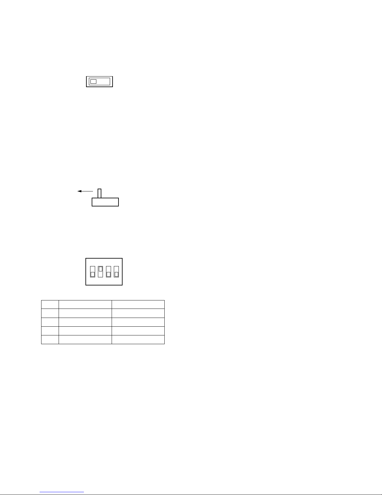
2. Set switches (SW101, SW201, SW301, SW401, SW501,
SW601, SW701, and SW801) on the board to choose
either data termination ON or OFF as shown below.
The factory default settings are TERM ON.
TERM
ON
TERM
OFF
3. Set switches (SW102, SW202, SW302, SW402, SW502,
SW602, SW702, and SW802) on the board to choose
either Full Duplex (4 LINE) or Half Duplex (2 LINE) communication lines as shown below.
The factory default settings are Full Duplex (4 LINE).
4LINE 2LINE
4. Confirm that switches (SW3) on the board are set to the
positions as shown below.
1234
OFF
DIP ON
1 One way mode
2 No retry mode
3 Reserved
4 Reserved
OFF
Handshake mode
3 retries mode
Reserved
Reserved
Page 23
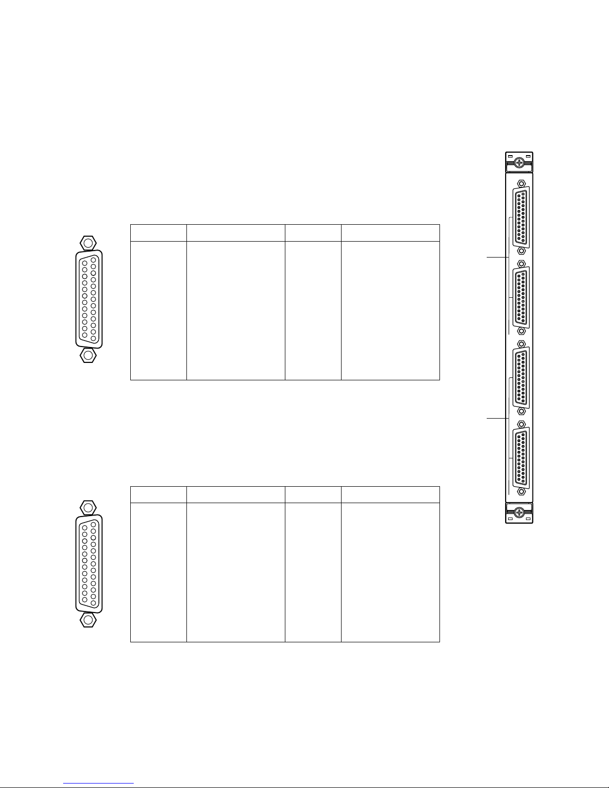
24
WJ-PB85C16 Crosspoint Input Board
■ Preface
The WJ-PB85C16 Crosspoint Input Board is an optional board for expanding the crosspoint input
capability of the System 850 Matrix Switcher.
■ Appearance
q Video Input Port (VIDEO IN, 1 - 2)
These ports accept either video signal from the VIDEO OUT port on the Camera Input Board
of the Camera Control Cage (MXCONT) or from the VIDEO OUT port on the Crosspoint Input
Board of another Crosspoint Cage (MXSW).
q
w
1
2
VIDEO IN
1
2
VIDEO OUT
INPUT
17
16
15
14
5
4
3
2
1
20
19
18
8
6
23
22
21
11
10
9
7
25
24
13
12
1
VIDEO 1
VIDEO 2
VIDEO 3
VIDEO 4
VIDEO 5
VIDEO 6
VIDEO 7
VIDEO 8
Not Used
Not Used
Not Used
Not Used
Pin No. Designation
25
24
23
22
21
20
19
18
17
16
15
14
Pin No. Designation
13
12
11
10
9
8
7
6
5
4
3
2
1
Ground
Ground
Ground
Ground
Ground
Ground
Ground
Ground
Ground
Ground
Ground
Ground
Ground
w Video Output Port (VIDEO OUT, 1 - 2)
The video signal connected to the VIDEO IN port is looped through to these ports.
If video output extensions are required, connect between these ports and the VIDEO IN ports
on the WJ-PB85C16 Crosspoint Input Board of another Crosspoint Cage (MXSW) for switching camera input.
17
16
15
14
5
4
3
2
1
20
19
18
8
6
23
22
21
11
10
9
7
25
24
13
12
2
VIDEO 9
VIDEO 10
VIDEO 11
VIDEO 12
VIDEO 13
VIDEO 14
VIDEO 15
VIDEO 16
Not Used
Not Used
Not Used
Not Used
Pin No. Designation
25
24
23
22
21
20
19
18
17
16
15
14
Pin No. Designation
13
12
11
10
9
8
7
6
5
4
3
2
1
Ground
Ground
Ground
Ground
Ground
Ground
Ground
Ground
Ground
Ground
Ground
Ground
Ground
Page 24
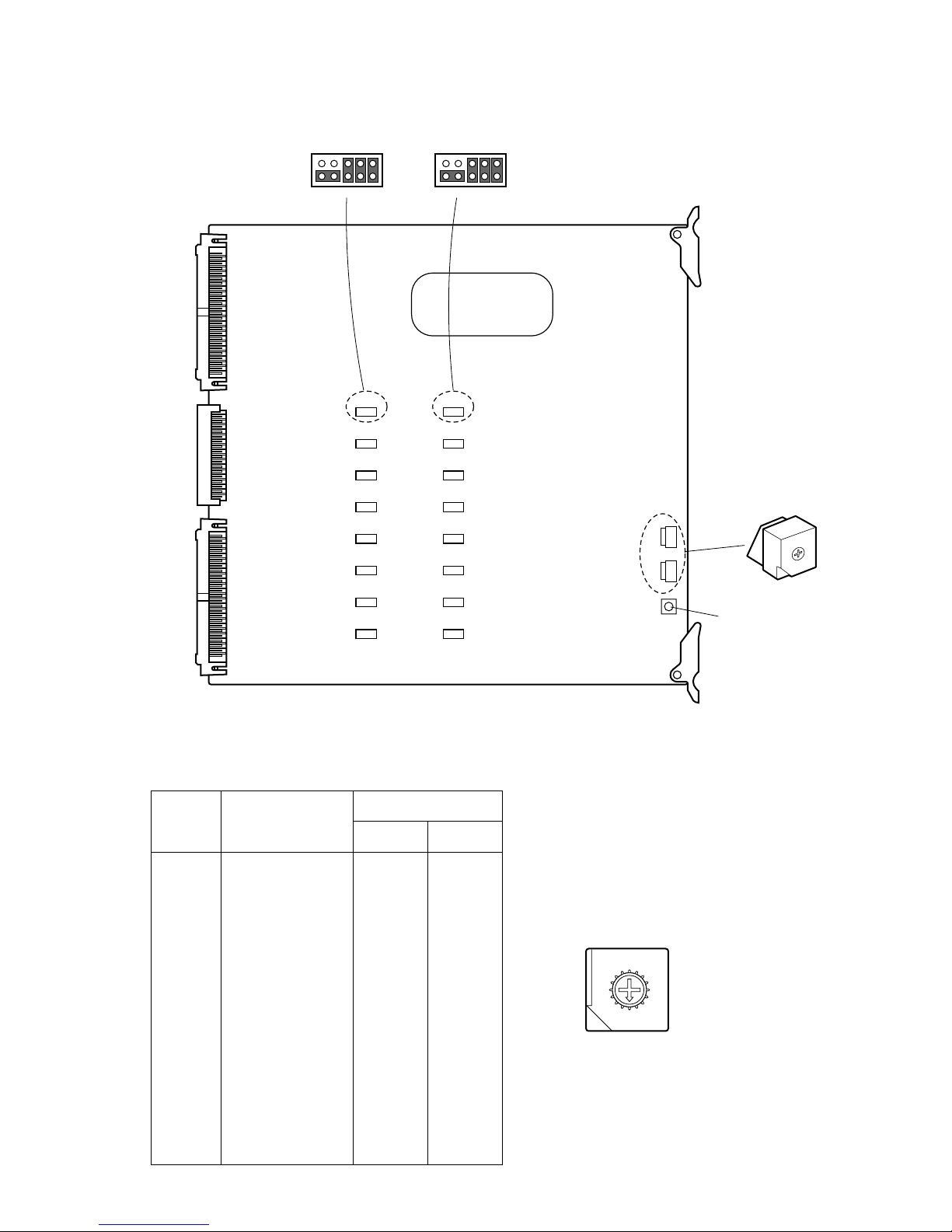
25
SW903SW902
0
1
2
3
4
5
6
7
8
9
A
B
C
D
E
F
CN151 CN101
CN251 CN201
CN351 CN301
CN451 CN401
CN551 CN501
CN651 CN601
CN751 CN701
CN851 CN801
VIDEO CROSS POINT
CN151
2
19
10
CN101
2
19
10
SW951
Reset Switch
Board
No.
VIDEO IN/OUT
SW Positions
SW903 SW902
1
2
3
4
5
6
7
8
9
10
11
12
13
14
15
16
0
0
0
0
0
0
0
0
0
0
0
0
0
0
0
0
0
1
2
3
4
5
6
7
8
9
A
B
C
D
E
F
1 - 16
17 - 32
33 - 48
49 - 64
65 - 80
81 - 96
97 - 112
113 - 128
129 - 144
145 - 160
161 - 176
177 - 192
193 - 208
209 - 224
225 - 240
241 - 256
1. Set switches (SW902 and SW903) on the board to designate the crosspoint input board number as shown in the following
table.
The factory default setting is Board Number 1 (00).
8
9
A
B
C
D
E
F
0
1
2
3
4
5
6
7
■ Board Setting
Before installing this board, the following settings should be made by qualified service personnel or system installers.
Page 25
26
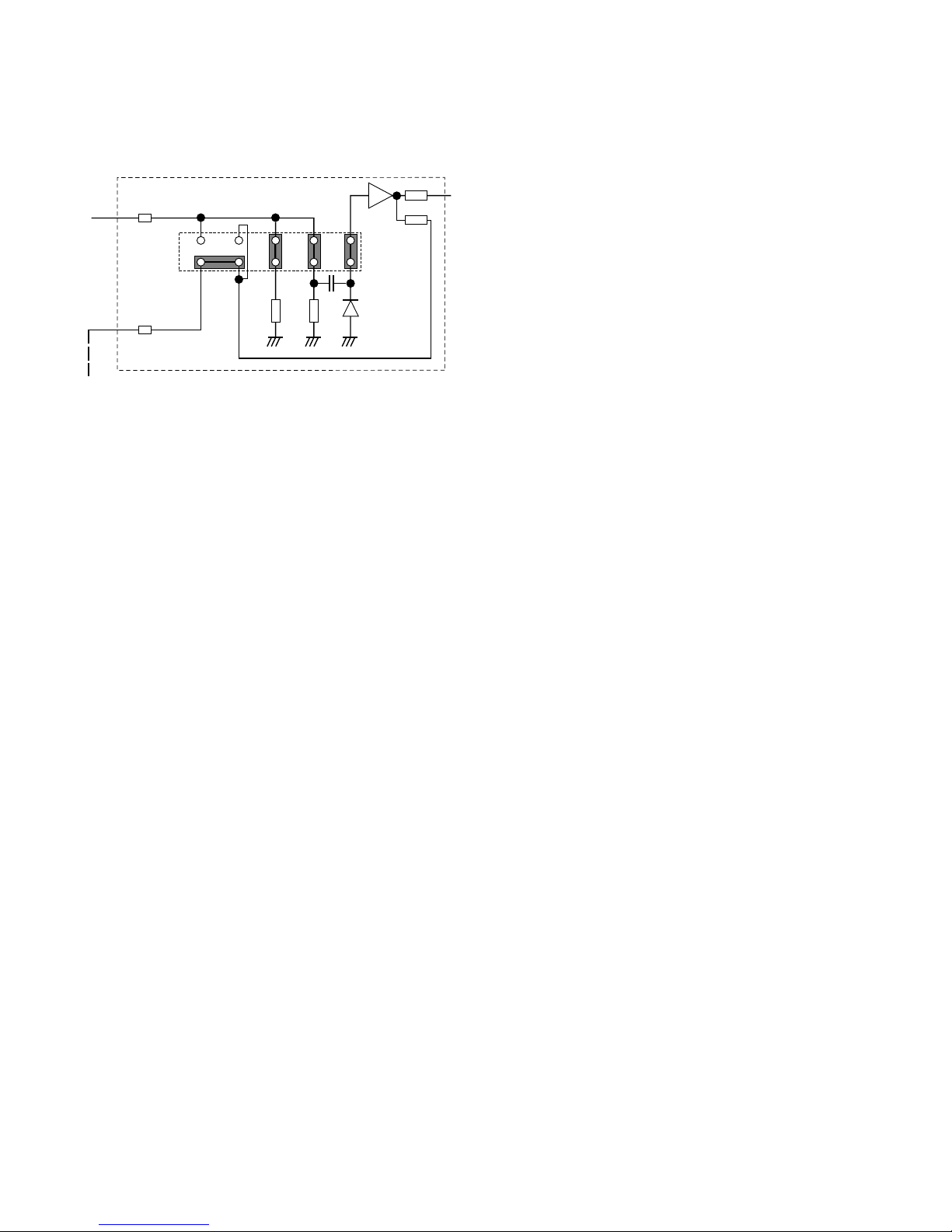
2. Position jumper connectors (CN101, CN151, CN201,
CN251, CN301, CN351, CN401, CN451, CN501,
CN551, CN601, CN651, CN701, CN751, CN801, and
CN851) on the board as shown below.
246810
1579
75 Ω
75 Ω
Clamping
Circuit
VIDEO IN
VIDEO OUT
3
Crosspoint input for 1 channel
The jumper connector positions designate the following
functions:
• Video Input Termination
5 and 6 Closed: 75 Ω termination
5 and 6 Open: High Z (impedance) termination
• Clamping Circuit
8 and 10 , 7 and 9 Closed: Off
7 and 8 , 9 and 10 Closed: On
• Video Output Mode
1 and 2 , 3 and 4 Closed: Wired Loop-Through
1 and 3 , 2 and 4 Closed: Buffered Through
For further details on settings, refer to the
appendix.
Page 26
27
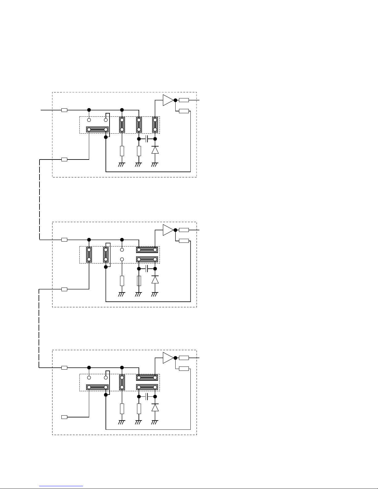
■ Appendix
● Jumper Connector Positions for Cage Extension
Examples of jumper connector settings are shown below.
Note: If the system is smaller than 1 024 inputs times 128 outputs, the settings (factory default) may not need to be
changed for extensions.
246810
1579
75 Ω
75 Ω
Clamping
Circuit
VIDEO IN
VIDEO OUT
2468
153
3
7
10
9
75 Ω
75 Ω
Clamping
Circuit
VIDEO IN
VIDEO OUT
2468
1
3
57
10
9
75 Ω
75 Ω
Clamping
Circuit
VIDEO IN
VIDEO OUT
Crosspoint input for 1 channel
75 Ω input, Buffered through, Clamp ON
75 Ω input, Buffered through, Clamp OFF
HI-Z input, Wired through, Clamp off
Initial-stage cage: (example MXSW 1-1, 1-2
and 1-3)
• Video input is received at the input circuit terminated at 75 Ω.
• The through circuit used to transfer the same input
signal to another cage is buffered in this cage
before 75 Ω transmission.
• The signal output is clamped before sending it out
to the board circuit to adjust the black level to that of
another input signal.
• The above are the factory default settings.
Middle-stage cage: Other than the initial and
final stages
• No clamping circuit is required because the signal
input has already been clamped at the initial stage
and buffered by the DC amplifier.
• To transfer the same input signal to the next-stage
cage, position the jumper connectors for wired loopthrough. With a wired system, a failure of the power
supply to the middle-stage cage would not cause
any problem in the successive stages.
Note: If the video output is 65 or more, this middle-
stage cage may need further extension.
Final-stage cage: (example MXSW 4-1, 4-2 and
4-3)
• In the final stage, the signal sent from the initial
stage is matched to 75 Ω. The video signal therefore
is received at the input circuit terminated at 75 Ω.
• No clamping is required here because the signal
input is already clamped as in the middle stage.
• The output signal for monitoring and other equipment is buffered through.
Page 27
28
246810
13579
75 Ω
75 Ω
Clamping
Circuit
VIDEO IN
VIDEO OUT
246810
13579
75 Ω
75 Ω
Clamping
Circuit
VIDEO IN
VIDEO OUT
246810
13579
75 Ω
75 Ω
Clamping
Circuit
VIDEO IN
VIDEO OUT
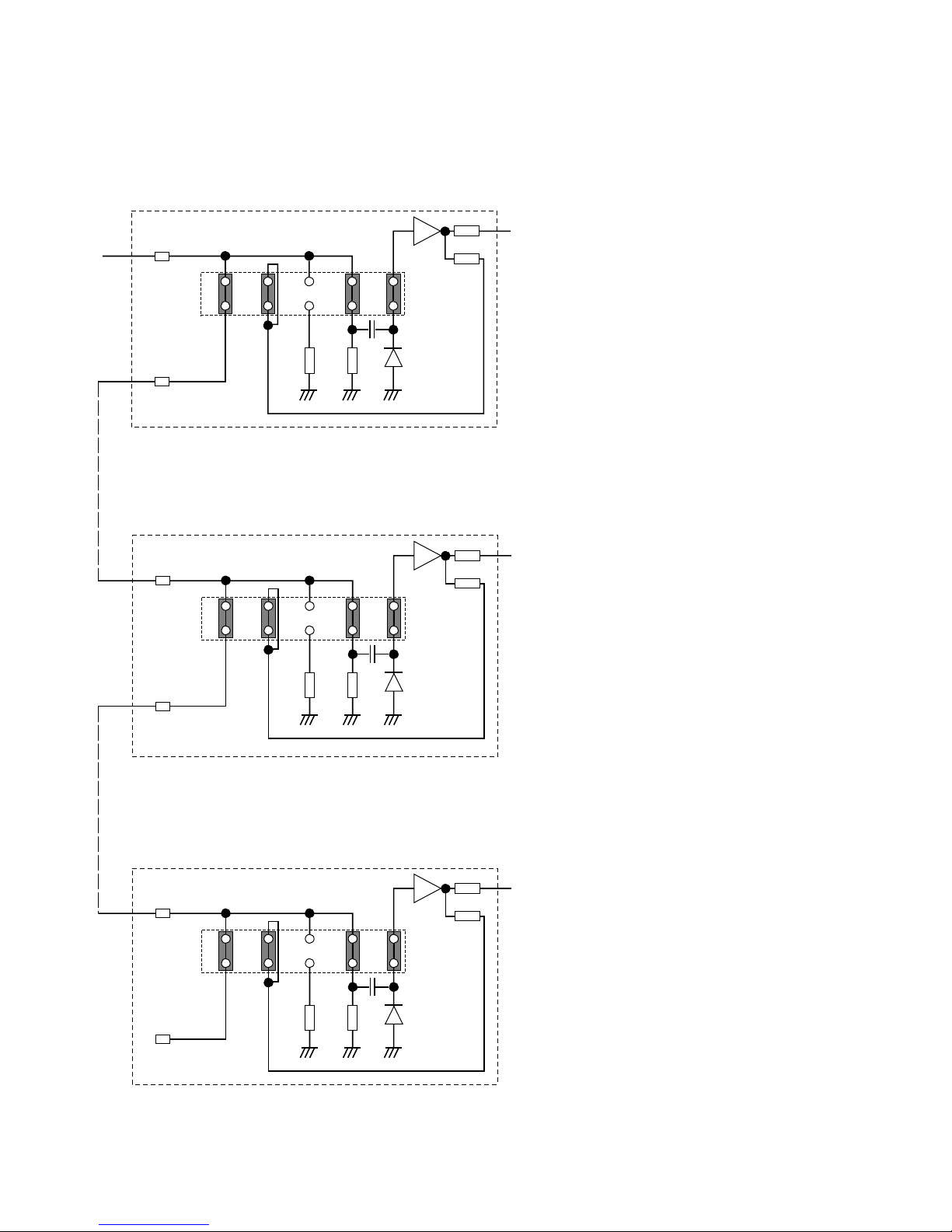
Hi-Z input, Wired through, Clamp on
Hi-Z input, Wired through, Clamp on
Hi-Z input, Wired through, Clamp on
Crosspoint input for 1 channel
Initial-stage cage:
• Video input is received at the input circuit terminated at a high impedance.
• Wire the through circuit to be used for transferring
the same input signal to another cage.
• The signal output is clamped before sending it out
to the board circuit to adjust the black level to that of
another input signal.
Middle-stage cage:
• Position the jumper connectors as for the initial
stage cage.
Final-stage cage:
• Position the jumper connectors as for the initialstage cage.
• When the jumper connectors are in this position,
there is no 75 Ω drive for VIDEO OUT. If output is
required at 75 Ω termination, change jumper positions 1-2 and 3-4 to 1-3.
● Jumper Connector Positions for Cage Extension
When the input video signal is terminated at another unit and it need be received at a Hi-Z impedance, position jumper
connectors on the board to the position shown below.
Page 28
29
WJ-PB85M16 Crosspoint Output Board
■ Preface
The WJ-PB85M16 Crosspoint Output Board is an optional board for expanding the crosspoint
output capability of the System 850 Matrix Switcher.
■ Appearance
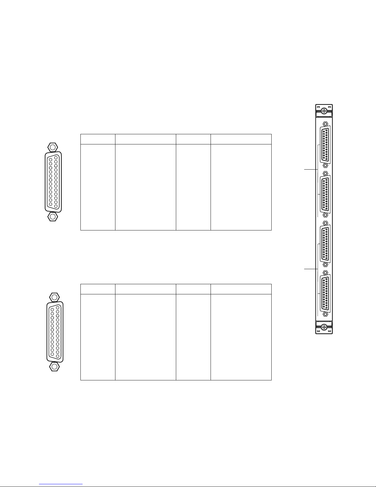
q Video Input Port (VIDEO IN, 1 - 2)
These ports accept the video signal from the VIDEO OUT Port on the WJ-PB85M16
Crosspoint Output Board of another Crosspoint Cage (MXSW) for cascade input.
q
w
1
2
VIDEO IN
1
2
VIDEO OUT
OUTPUT
17
16
15
14
5
4
3
2
1
20
19
18
8
6
23
22
21
11
10
9
7
25
24
13
12
1
VIDEO 1
VIDEO 2
VIDEO 3
VIDEO 4
VIDEO 5
VIDEO 6
VIDEO 7
VIDEO 8
Not Used
Not Used
Not Used
Not Used
Pin No. Designation
25
24
23
22
21
20
19
18
17
16
15
14
Pin No. Designation
13
12
11
10
9
8
7
6
5
4
3
2
1
Ground
Ground
Ground
Ground
Ground
Ground
Ground
Ground
Ground
Ground
Ground
Ground
Ground
17
16
15
14
5
4
3
2
1
20
19
18
8
6
23
22
21
11
10
9
7
25
24
13
12
2
VIDEO 9
VIDEO 10
VIDEO 11
VIDEO 12
VIDEO 13
VIDEO 14
VIDEO 15
VIDEO 16
Not Used
Not Used
Not Used
Not Used
Pin No. Designation
25
24
23
22
21
20
19
18
17
16
15
14
Pin No. Designation
13
12
11
10
9
8
7
6
5
4
3
2
1
Ground
Ground
Ground
Ground
Ground
Ground
Ground
Ground
Ground
Ground
Ground
Ground
Ground
w Video Output Port (VIDEO OUT, 1 - 2)
These ports provide the video signal to the VIDEO IN Port on the WJ-PB85M16 Crosspoint
Output Board of another Crosspoint Cage (MXSW), or to the VIDEO IN Port on the WJPB85T08 On-Screen Display Board of the On-Screen Display Cage (MXOSD) for expanding
video output capability.
Page 29
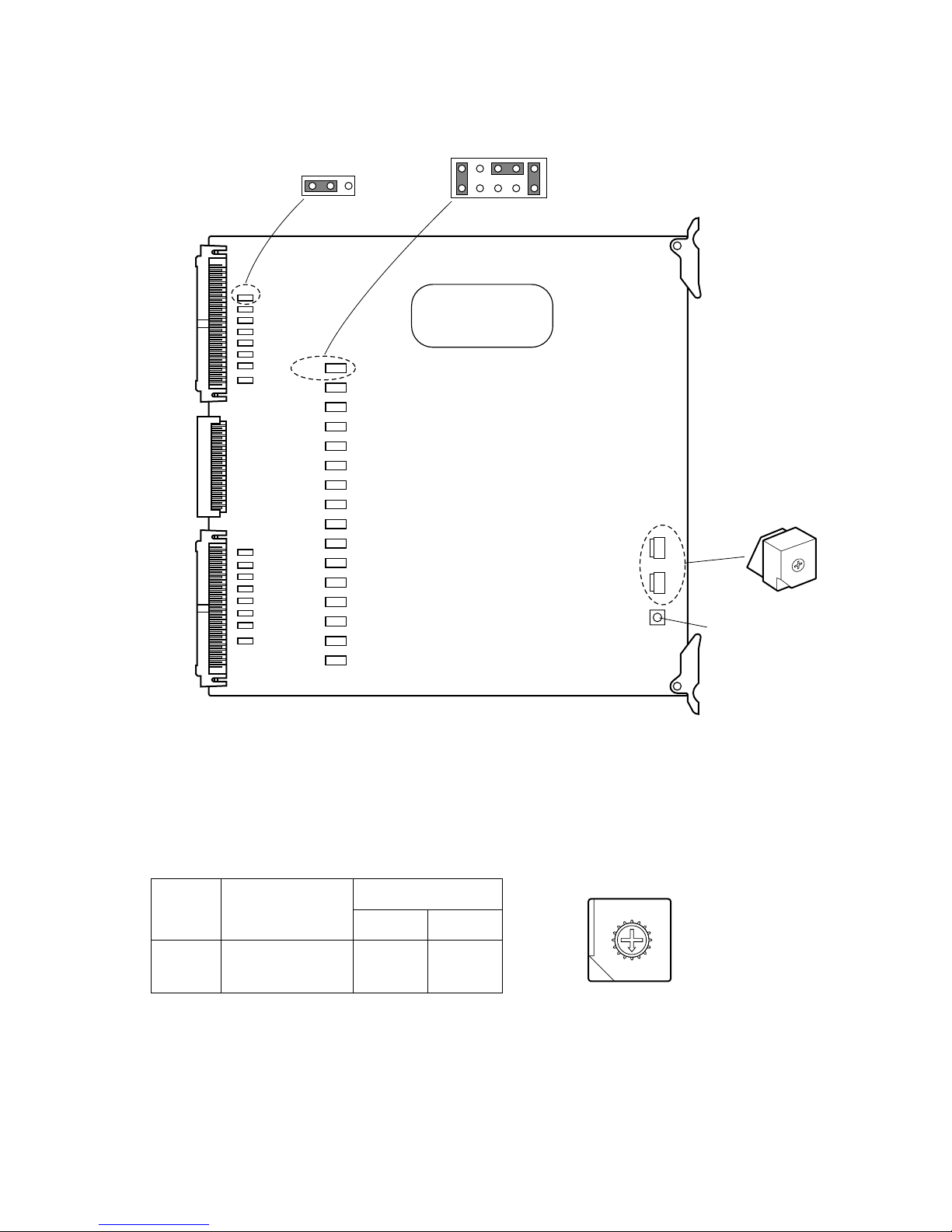
30
SW703SW702
0
1
2
3
4
5
6
7
8
9
A
B
C
D
E
F
CN201
CN202
CN203
CN204
CN205
CN206
CN207
CN208
CN209
CN210
CN211
CN212
CN213
CN214
CN215
CN216
CN232
CN225
CN224
CN223
CN217
CN232
CN201
13
2
10
1
9
SW1
Reset Switch
Board
No.
VIDEO IN/OUT
SW Positions
SW703 SW702
1
2
0
0
0
1
1 - 16
17 - 32
1. Set switches (SW702 and 703) on the board to designate the crosspoint output board number as shown in the following
table.
The factory default setting is Board Number 1 (00).
8
9
A
B
C
D
E
F
0
1
2
3
4
5
6
7
■ Board Setting
Before installing this board, the following settings should be made by qualified service personnel or system installers.
Page 30
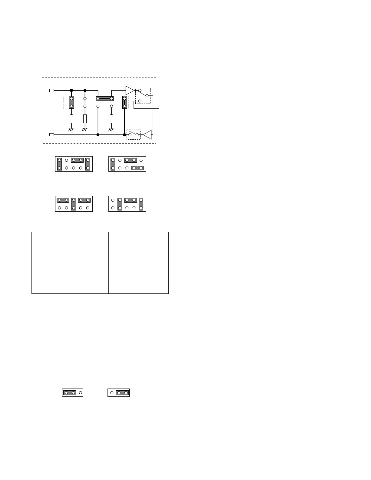
31
2. Position jumper connectors (CN201, CN202, CN203,
CN204, CN205, CN206, CN207, CN208, CN209,
CN210, CN211, CN212, CN213, CN214, CN215,
CN216) on the board as shown below.
The factory default setting is position MODE A (Normal).
246 10
13579
150 Ω150 Ω75 Ω
VIDEO IN
VIDEO OUT
S2
S
246810
13579
MODE A
Default Setting
246810
13579
MODE B
246810
13579
MODE C
246810
13579
MODE D
MODE Input Spec. Output Spec.
MODE A
MODE B
MODE C
MODE D
75 Ω Termination
75 Ω Termination
Hi-Z Termination
150 Ω Termination
75 Ω Buffered Output
75 Ω with 150 Ω
Termination Buffered
Output
Wired Loop-Through
75 Ω Buffered Output
For further details on settings, refer to the appendix.
3. When two crosspoint output boards are installed in a
Crosspoint Cage (MXSW), position jumper connectors
(CN217, CN218, CN219, CN220, CN221, CN222,
CN223, CN224, CN225, CN226, CN227, CN228,
CN229, CN230, CN231, CN232) on the board to assign
outputs as shown below.
The factory default setting is positions 1 and 2.
13
Output 1-16
Default Setting
13
Output 17-32
Page 31
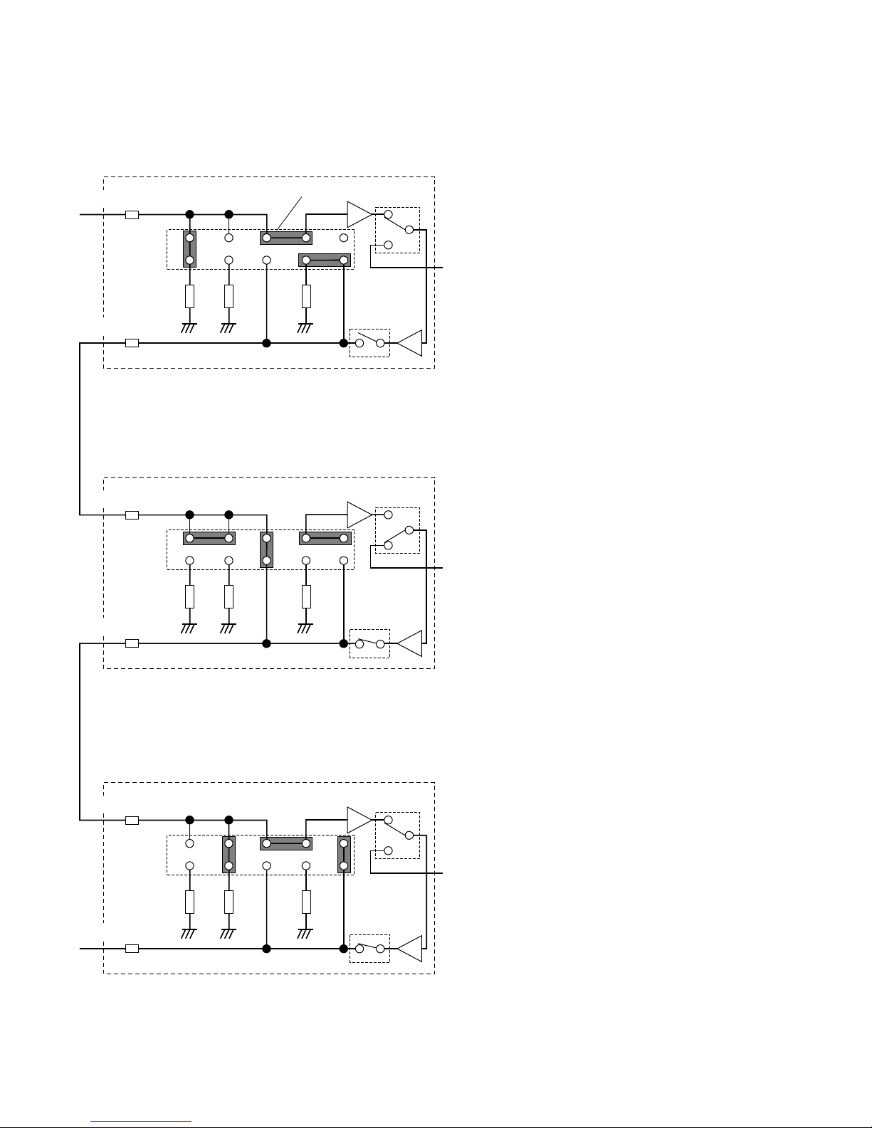
32
■ Appendix
● Jumper Connector Positions for Cage Extension
Examples of jumper connector settings are shown below.
Note: If the system is smaller than 1 024 inputs times 128 outputs, the settings (factory default settings) may not
need to be changed for extensions.
246 10
1357
150 Ω150 Ω75 Ω
VIDEO IN
VIDEO OUT
268
13579
150 Ω150 Ω75 Ω
VIDEO IN
VIDEO OUT
246 10
13579
150 Ω150 Ω75 Ω
VIDEO IN
VIDEO OUT
S2
S2
S2
S
S
S
Termination for 75 Ω input and 150 Ω output
Hi-Z input
Termination for 150 Ω input
Crosspoint output for 1 channel
Jumper post on the board
Initial-stage cage: (example MXSW 1-3, 2-3, 3-3
and 4-3)
• This stage has a configuration that enables it to
accept an extended video input in the form of an
input terminated at 75 Ω. Actually, however, this
external input terminal is invalid.
• When an input of this cage is selected, S of this
cage is turned on and S of other cages is turned off.
• In order to secure 75 Ω for signal send-out from the
initial stage, a 150 Ω termination is provided for the
75 Ω impedance drive and another 150 Ω termination is provided at the final stage.
Middle-stage cage: Other than the initial and
final stages
• When an input of this cage is selected, S of this
cage is turned on and S of other cages is turned off.
• A wired loop-through system is used for the common output video bus of the cage. Therefore, a failure of the power supply to the middle-stage cage
would not cause any problem in the successive
stages.
Note: If the video input is 768 or more, this middle-
stage cage may need further extension.
Final-stage cage: (example MXSW 1-1, 2-1, 3-1
and 4-1)
• The selected output of all crosspoint inputs obtained
at the final stage is generated from the VIDEO OUT
terminal of this cage and can be applied to a video
monitor.
• S of this cage is turned on at all times. S2 is used for
the changeover between the crosspoint input of this
cage and that of other cages.
Page 32
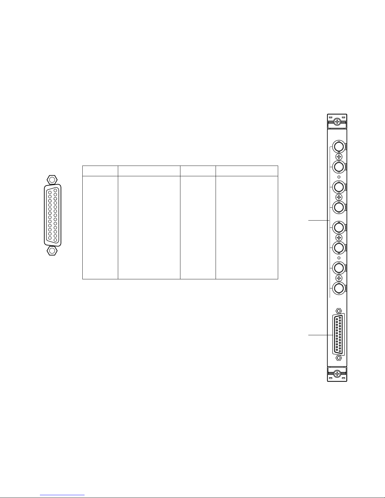
33
WJ-PB85T08 OSD (On-Screen Display) Board
■ Preface
The WJ-PB85T08 On-Screen Display Board is an optional board for displaying the camera title,
clock, and system status on the active monitors.
■ Appearance
q Monitor Output Connector (MONITOR OUT, 1 - 8)
Outputs the video signal connected to the VIDEO IN port with the character display for the
video monitor.
w Video Input Port (VIDEO IN)
Accepts the video signal from the VIDEO OUT Port on the WJ-PB85M16 Crosspoint Output
Board of the Crosspoint Card cage (MXSW).
1
2
3
4
5
6
7
8
MONITOR OUT
VIDEO IN
OSD
q
w
17
16
15
14
5
4
3
2
1
20
19
18
8
6
23
22
21
11
10
9
7
25
24
13
12
Pin No. Designation
25
24
23
22
21
20
19
18
17
16
15
14
VIDEO 1
VIDEO 2
VIDEO 3
VIDEO 4
VIDEO 5
VIDEO 6
VIDEO 7
VIDEO 8
Not used
Not used
Not used
Not used
Pin No. Designation
13
12
11
10
9
8
7
6
5
4
3
2
1
Ground
Ground
Ground
Ground
Ground
Ground
Ground
Ground
Ground
Ground
Ground
Ground
Ground
Page 33
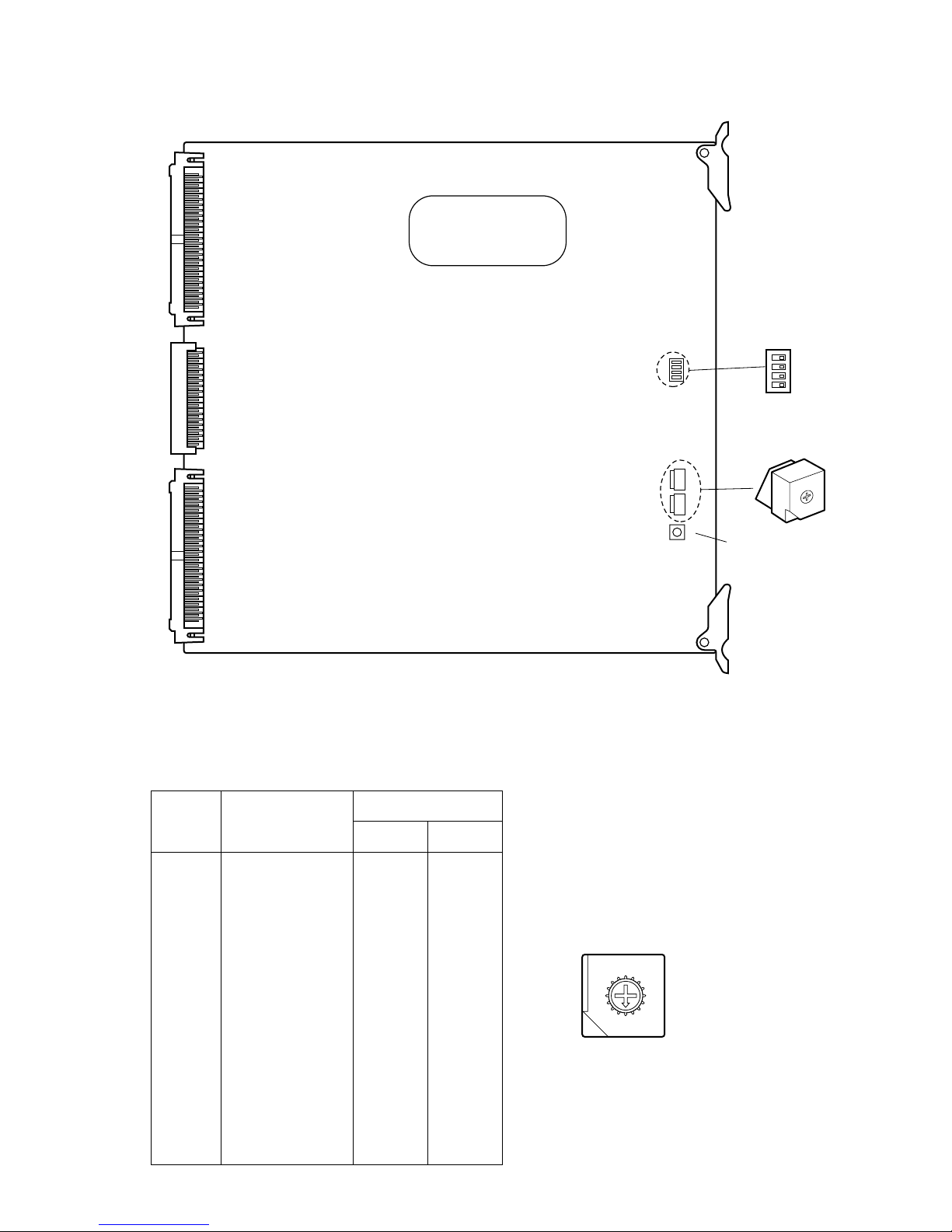
34
SW Positions
Monitor Output
Board
No.
SW2 SW1
1
2
3
4
5
6
7
8
9
10
11
12
13
14
15
16
0
0
0
0
0
0
0
0
0
0
0
0
0
0
0
0
0
1
2
3
4
5
6
7
8
9
A
B
C
D
E
F
1 - 8
9 - 16
17 - 24
25 - 32
33 - 40
41 - 48
49 - 56
57 - 64
65 - 72
73 - 80
81 - 88
89 - 96
97 - 104
105 - 112
113 - 120
121 - 128
■ Board Setting
Before installing this board, the following settings should be made by qualified service personnel or system installers.
SW3
SW2SW1SW5
OFF
1234
0
1
2
3
4
5
6
7
8
9
A
B
C
D
E
F
Reset Switch
1. Set switches (SW1 and SW2) on the board to designate the on-screen display board number as shown in the following
table.
The factory default setting is Board Number 1 (00).
8
9
A
B
C
D
E
F
0
1
2
3
4
5
6
7
Page 34
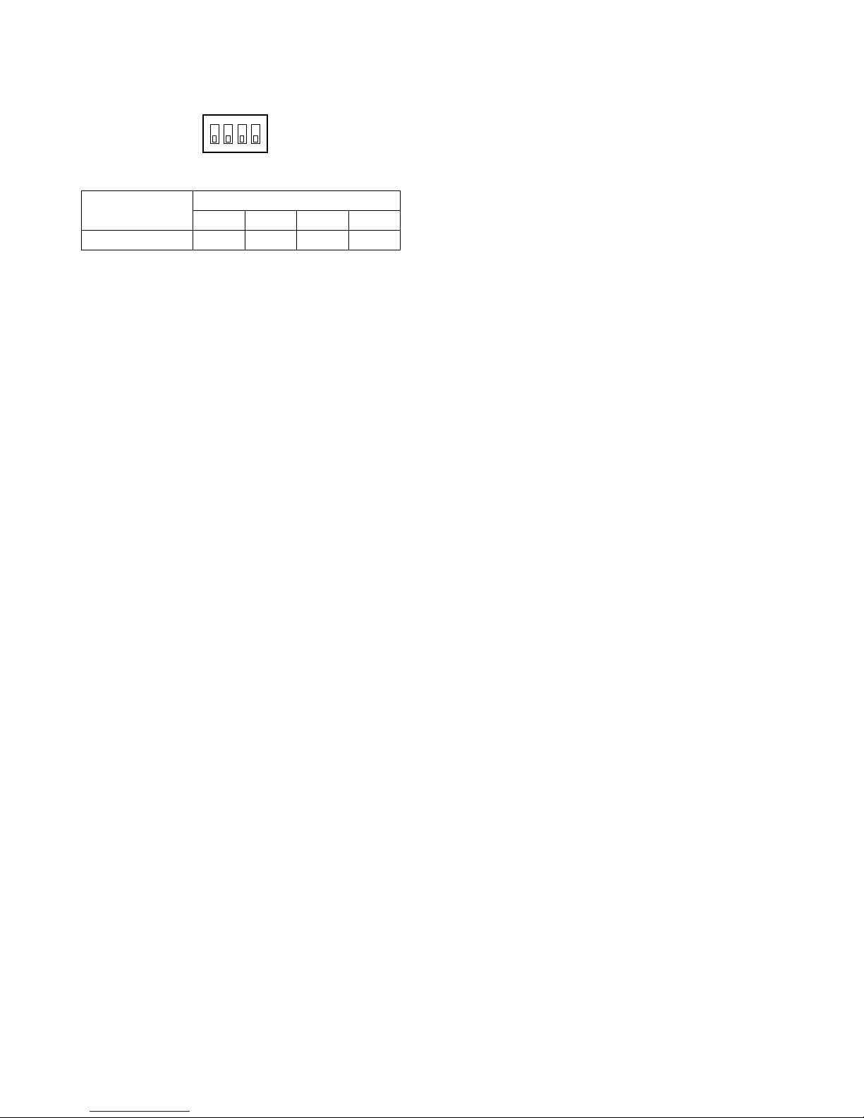
35
1
Switch Positions
2. Confirm that switches (SW3) on the board are set to the
OFF position as shown below.
SW3
OFF
1234
432
Switch Number
OFFOFFOFFOFFSW3
Page 35
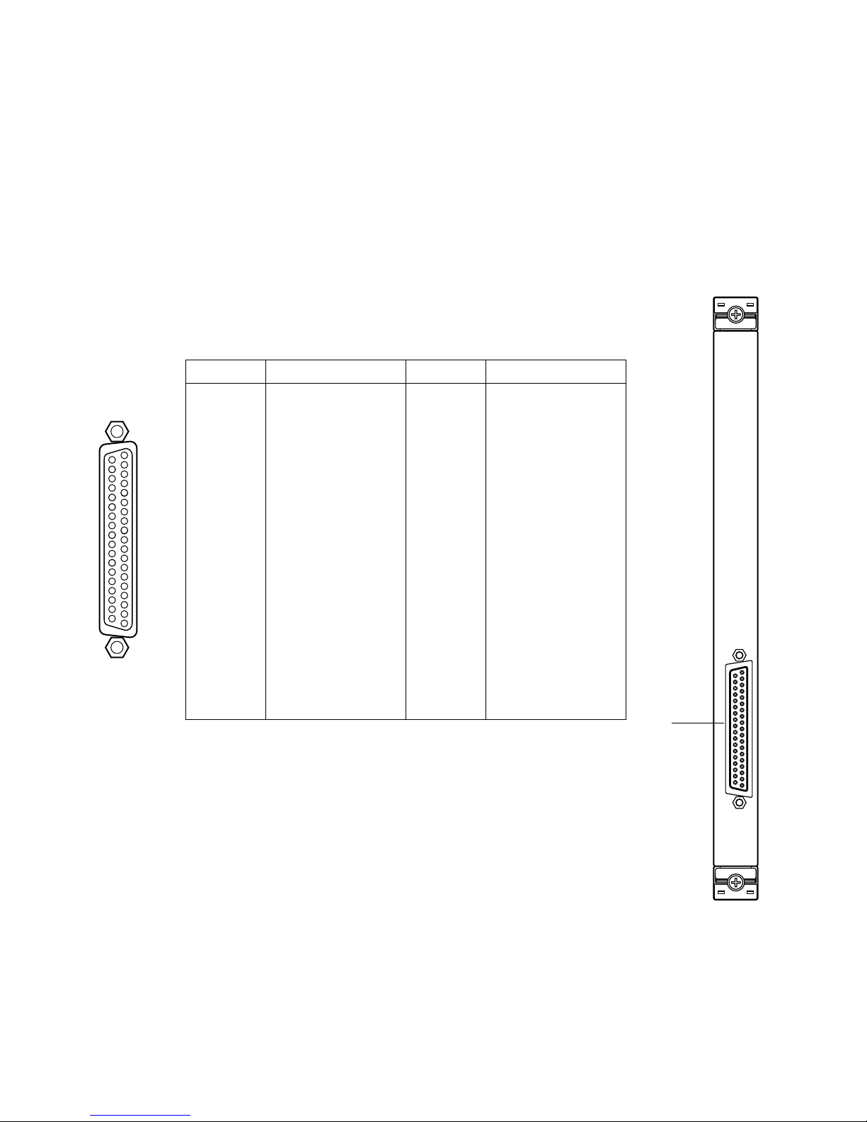
36
1-32
ALARM
IN
q
Ground
Ground
Not used
Not used
Not used
Alarm 32
Alarm 31
Alarm 30
Alarm 29
Alarm 28
Alarm 27
Alarm 26
Alarm 25
Alarm 24
Alarm 23
Alarm 22
Alarm 21
Alarm 20
Pin No. Designation
37
36
35
34
33
32
31
30
29
28
27
26
25
24
23
22
21
20
Pin No. Designation
19
18
17
16
15
14
13
12
11
10
9
8
7
6
5
4
3
2
1
Alarm 19
Alarm 18
Alarm 17
Alarm 16
Alarm 15
Alarm 14
Alarm 13
Alarm 12
Alarm 11
Alarm 10
Alarm 9
Alarm 8
Alarm 7
Alarm 6
Alarm 5
Alarm 4
Alarm 3
Alarm 2
Alarm 1
23
22
21
20
5
4
3
2
1
26
25
24
8
6
29
28
27
11
10
9
7
32
31
30
14
13
12
33
15
36
35
34
18
37
19
17
16
WJ-PB85A32 Alarm Input Board
■ Preface
The WJ-PB85A32 Alarm Input Board is an optional board for expanding the capabilities of the
System 850 Matrix Switcher.
It transmits a received alarm signal to the CPU (Central Processing Unit) via Ethernet to activate
the assigned alarm event.
The board can also be used an as alarm output board by changing the position of internal
switches.
■ Appearance
q Alarm Input Port (1 - 32)
This port accepts alarm input from the associated alarm sensors through either Normally
Open (N.O) or Normally Closed (N.C) contacts.
Page 36
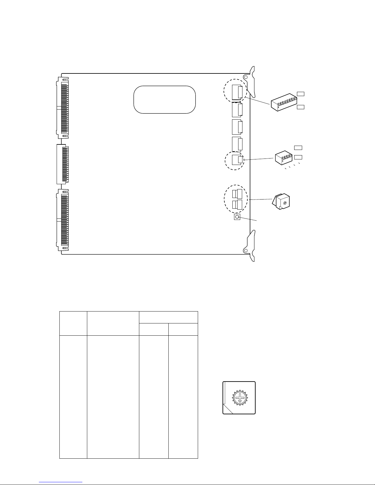
37
■ Board Setting
Before installing this board, the following settings should be made by qualified service personnel or system installers.
SW3 SW7 SW6 SW5 SW4
SW2
SW1SW8
ALARM INPUT BOARD
0
1
2
3
4
5
6
7
8
9
A
B
C
D
E
F
Reset Switch
1 2 3 4 5 6 7 8
ON
SW4
ON
OFF
CH1 - 8
1 2 3 4
SW3
OFF
ON
C
H
1 9 17 25
8 16 24 32
ON
Board
No.
Alarm Input
SW Positions
SW2 SW1
1
2
3
4
5
6
7
8
9
10
11
12
13
14
15
16
0
0
0
0
0
0
0
0
0
0
0
0
0
0
0
0
0
1
2
3
4
5
6
7
8
9
A
B
C
D
E
F
1 - 32
33 - 64
65 - 96
97 - 128
129 - 160
161 - 192
193 - 224
225 - 256
257 - 288
289 - 320
321 - 352
353 - 384
385 - 416
417 - 448
449 - 480
481 - 512
1. Set switches (SW1 and SW2) on the board to designate the alarm input board number as shown in the following table.
The factory default setting is Board Number 1 (00).
8
9
A
B
C
D
E
F
0
1
2
3
4
5
6
7
Page 37

38
2. Set switches (SW4, SW5, SW6, and SW7) on the board
to meet the alarm input requirements.
ON: Normally Closed (N.C)
OFF: Normally Open (N.O)
The factory default settings are OFF.
1 2 3 4 5 6 7 8
ON
SW4
ON
OFF
CH1 - 8
3. If this board is used for Alarm Output, set switches
(SW3) on the board as follows.
ON: Output mode
OFF: Input mode
The factory default settings are OFF.
1 2 3 4
SW3
OFF
ON
C
H
1 9 17 25
8 16 24 32
ON
Page 38
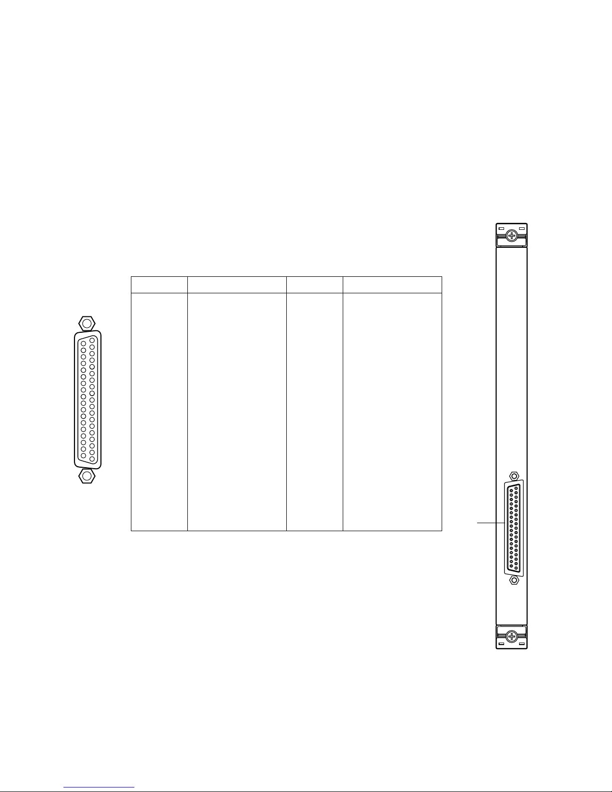
39
WJ-PB85L32 Alarm Output Board
■ Preface
The WJ-PB85L32 Alarm Output Board is an optional board for expanding the capabilities of the
System 850 Matrix Switcher.
A received alarm signal, and a pulse generated in the Digital Output operation by the controller,
are transmitted to the CPU (Central Processing Unit) via Ethernet to enable control of the alarm
contacts on this board.
The board can also output the status of any alarm activated by the camera's motion detector,
alarm acknowledgment and alarm reset.
■ Appearance
q Alarm Output Port (1 - 32)
This port supplies alarm output to the actuators connected to it through either Normally Open
(N.O) or Normally Closed (N.C) contacts on this board.
1-32
ALARM
OUT
q
23
22
21
20
5
4
3
2
1
26
25
24
8
6
29
28
27
11
10
9
7
32
31
30
14
13
12
33
15
36
35
34
18
37
19
17
16
Ground
Ground
Not used
Not used
Not used
Alarm 32
Alarm 31
Alarm 30
Alarm 29
Alarm 28
Alarm 27
Alarm 26
Alarm 25
Alarm 24
Alarm 23
Alarm 22
Alarm 21
Alarm 20
Pin No. Designation
37
36
35
34
33
32
31
30
29
28
27
26
25
24
23
22
21
20
Pin No. Designation
19
18
17
16
15
14
13
12
11
10
9
8
7
6
5
4
3
2
1
Alarm 19
Alarm 18
Alarm 17
Alarm 16
Alarm 15
Alarm 14
Alarm 13
Alarm 12
Alarm 11
Alarm 10
Alarm 9
Alarm 8
Alarm 7
Alarm 6
Alarm 5
Alarm 4
Alarm 3
Alarm 2
Alarm 1
Page 39
40
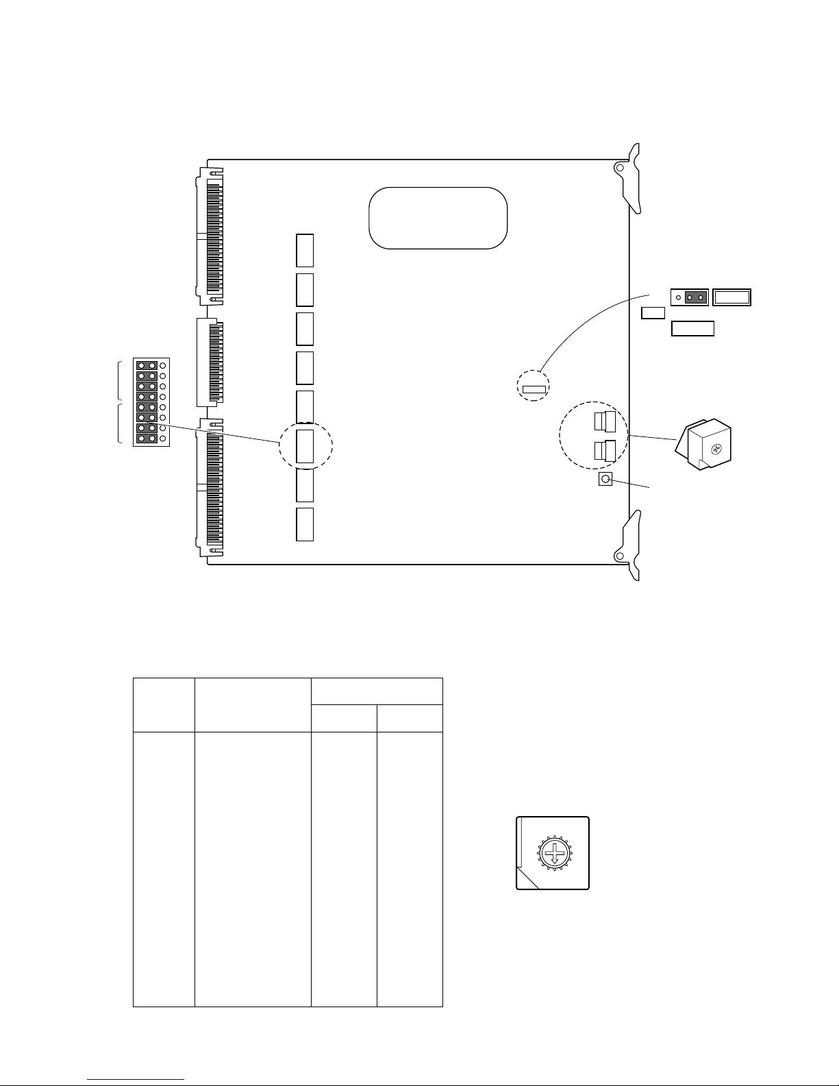
■ Board Setting
Before installing this board, the following settings should be made by qualified service personnel or system installers.
CN 290 CN 250 CN 210 CN 170 CN 130 CN 90 CN 50 CN 10
ALARM OUTPUT BOARD
0
1
2
3
4
5
6
7
8
9
A
B
C
D
E
F
21
22
23
24
21
22
23
24
NO/NC
GND/COM
CN210
SW 2
CN4
SW 1
SW 3
CN4
13
NOR
INV
Polarity
Reset Switch
Board
No.
Alarm Output
SW Positions
SW2 SW1
1
2
3
4
5
6
7
8
9
10
11
12
13
14
15
16
0
0
0
0
0
0
0
0
0
0
0
0
0
0
0
0
0
1
2
3
4
5
6
7
8
9
A
B
C
D
E
F
1 - 32
33 - 64
65 - 96
97 - 128
129 - 160
161 - 192
193 - 224
225 - 256
257 - 288
289 - 320
321 - 352
353 - 384
385 - 416
417 - 448
449 - 480
481 - 512
1. Set switches (SW1 and SW2) on the board to designate the alarm output board number as shown in the following table.
The factory default setting is Board Number 1 (00).
8
9
A
B
C
D
E
F
0
1
2
3
4
5
6
7
Page 40
41
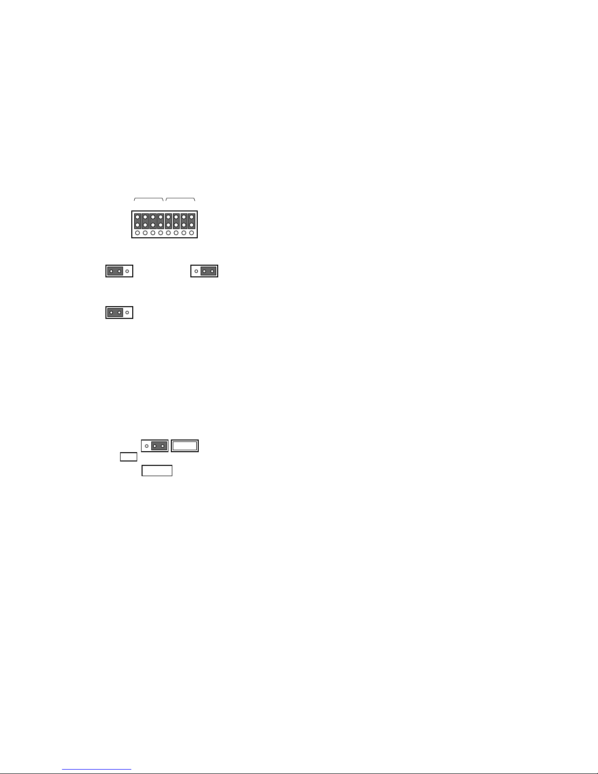
2. Position jumper connectors (CN10, CN50, CN90,
CN130, CN170, CN210, CN250, and CN290) on the
board to meet the alarm output requirements.
Select either Normally Open (N.O) or Normally Closed
(N.C) for the contact output, and then confirm that the
jumper connectors are positioned at Ground (GND) as
shown below.
The factory default settings are Normally Open (N.O).
21
22
23
24
21
22
23
24
NO/NC
GND/COM
CN210
Normally Open (N.O)
Default Setting
Normally Closed (N.C)
Ground (GND)
Default Setting
3. Confirm that the jumper connector (CN4) on the board
is positioned on 1 and 2.
This setting lets you select the output polarity.
CN4
13
NOR
INV
Polarity
Default Setting
Page 41
PARALLEL
SATELLITE
MODE
REDUNDANT
CPU
ETHERNET
1
CAMERA
CROSS POINT
OSD
GYGTEM
CONTROLLER
DATA 6 DATA 5 DATA 4 DATA 3 DATA 2 DATA 1
PERIFERAL INTERFACE (RS–232C
)
(
RS–485
)
SYSYTEM
CONTROLLER
23
SATELLITE
STANDALONE
YESNO
AC IN
Central Processing Unit
125V 3.0A
SIGNAL
GND
y u
o !0 !1
!2
!3
i
!4
42
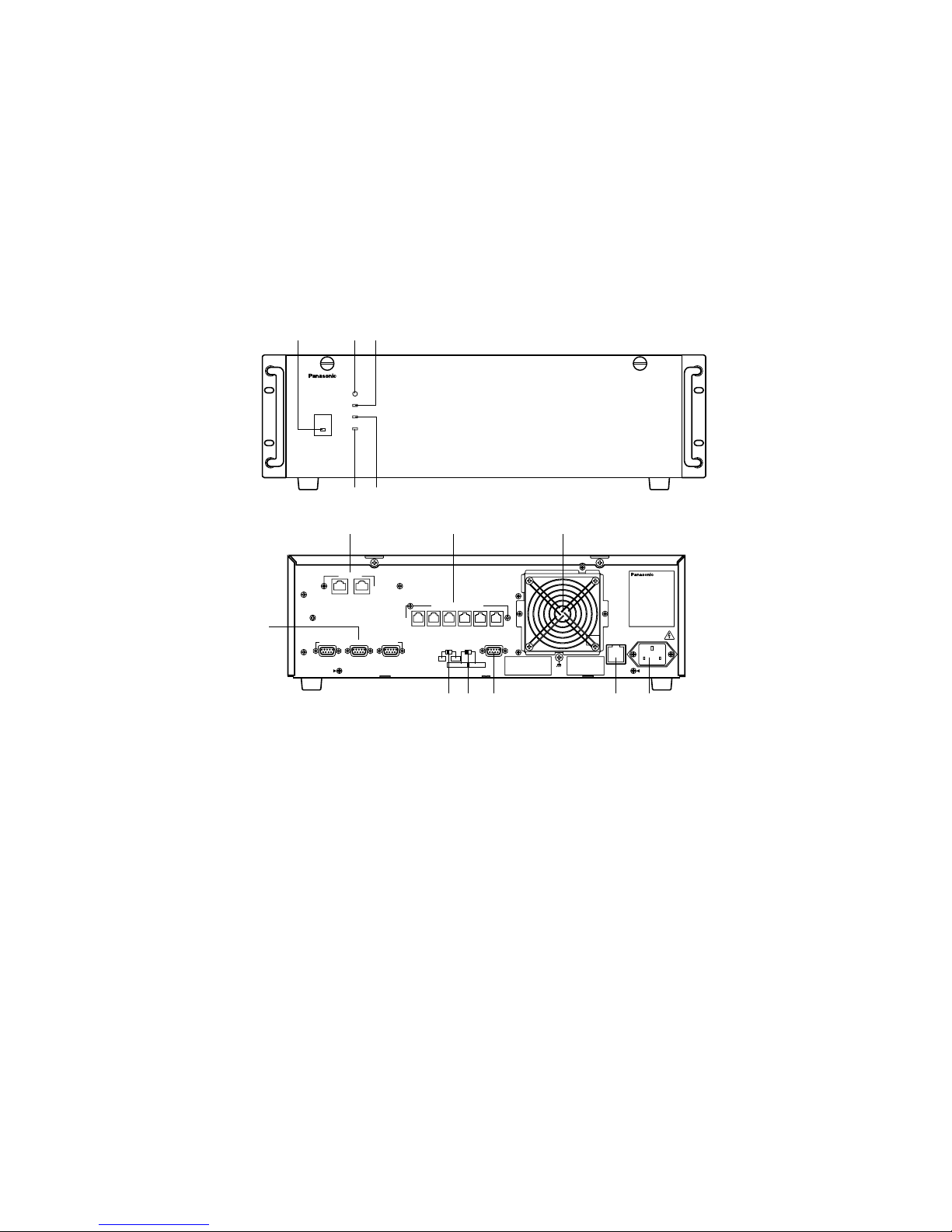
WJ-MPU850 Central Processing Unit
■ Preface
The WJ-MPU850 CPU is the Central Processing Unit for the System 850 Matrix Switcher. The System 850 Matrix Switcher is a
CCTV surveillance system having multiple video inputs, multiple video outputs, and multiple control stations. The WJ-MPU850
is capable of controlling a maximum of 512 video input sources and a maximum of 64 video outputs, such as monitors, with 16
system controllers.
The WJ-MPU850 is a high-performance Intel X86 processor based computer running the OS-9 real time operating system
allowing you to build up a redundant system of duplicate CPUs.
■ Appearance
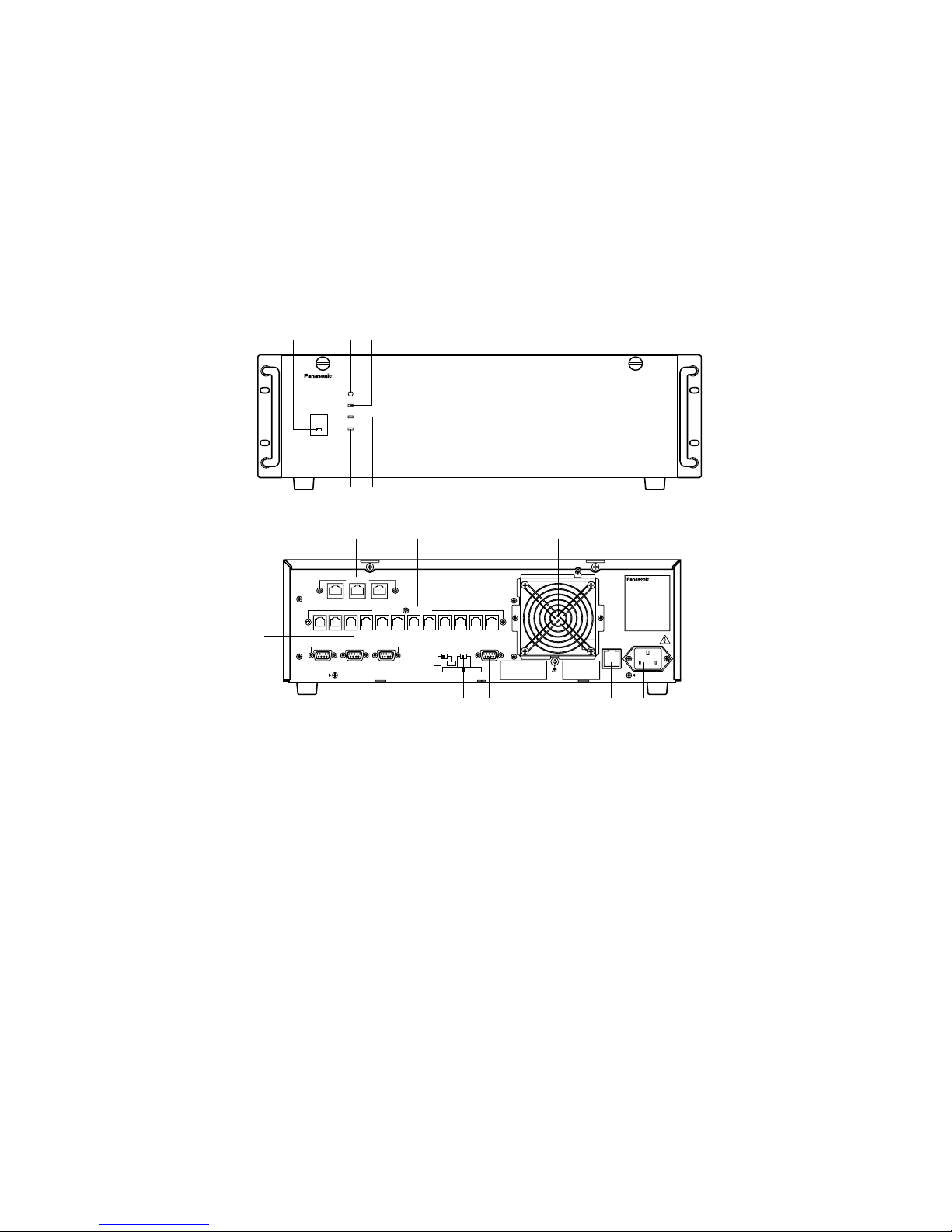
q Operate Indicator (OPERATE)
Is on when the power of the WJ-MPU850 CPU is turned
on.
Note: The power switch of the CPU is located under-
neath the front panel.
Remove the front panel by removing two screws on
the panel.
w Reset Button (RESET)
The RESET button is recessed inside the front panel
hole to the right of the OPERATE indicator.
Press this button when the CPU rejects control from
outboard equipment.
e Fan Alarm Indicator (FAN ALARM)
Indicates the cooling fan status.
This LED lights when a temperature rise in the CPU is
detected. Turn the power off and refer servicing to
qualified service personnel.
r HDD (Hard Disk Drive) Indicator (HDD)
Indicates the hard disk drive status.
OPERATE
RESET
FAN ALARM
HDD
ACTIVE
Control Processing Unit WJ–MPU
850
qw
tr
e
● Front View
● Rear View
t Active Indicator (ACTIVE)
Indicates the system status of the CPU.
y Ethernet Ports (ETHERNET)
Exchange control data via Ethernet.
• SYSTEM CONTROLLER
This port is provided for controlling the 850 System with
the WV-CU850 system controllers. Up to 16 controllers
can be connected to this port through a hub.
Note: The total number of system controllers connect-
ed via RS-485 and Ethernet is limited to 16.
• CAMERA/CROSS POINT/OSD
This port is used to exchange control data between the
cages through a hub.
u Controller Ports [SYSTEM CONTROLLER (RS-485)]
These ports are provided for controlling the 850 System
with the WV-CU350 system controllers. Up to 6 controllers can be connected
i Peripheral Interface Ports [PERIPHERAL
INTERFACE (RS-232C)]
These ports are reserved for future use or factory tests.
Page 42

43
o Redundant CPU selector (REDUNDANT CPU)
Selects either a redundant system or a standalone system.
The factory default setting is NO.
!0 Mode Selector (SATELLITE MODE)
Always keep in STANDALONE position.
!1 Parallel Port (PARALLEL)
This port is used to connect to the WJ-MPS850 CPU
Switch Unit for a redundant system.
!2 Cooling Fan Unit
Prevents the temperature of the CPU from rising.
Do not block the ventilation opening on the cover.
!3 Fuse Holder
!4 AC Inlet Socket (AC IN)
Plug the power cord (supplied as a standard accessory) into this socket and connect it to an AC outlet.
Page 43
44
WJ-MPU855 Central Processing Unit
■ Preface
The WJ-MPU855 CPU is the Central Processing Unit for the System 850 Matrix Switcher. The System 850 Matrix Switcher is a
CCTV surveillance system having multiple video inputs, multiple video outputs, and multiple control stations. The WJ-MPU855
is capable of controlling a maximum of 1 024 video input sources and a maximum of 256 video outputs, such as monitors, with
64 system controllers.
The WJ-MPU855 is a high-performance Intel X86 processor based computer running the OS-9 real time operating system
allowing you to build up a redundant system of duplicate CPUs.
■ Appearance
OPERATE
RESET
FAN ALARM
HDD
ACTIVE
Central Processing Unit WJ–MPU
855
qw
tr
e
● Front View
PARALLEL
REDUNDANT
CPU
RSATELLITE
MODE
ETHERNET
1
OTHER
CAMERA
CROSS POINT
OSD
GYGTEM
CONTROLLER
DATA 12 DATA 11 DATA 10 DATA 9 DATA 8 DATA 7 DATA 6 DATA 5 DATA 4 DATA 3 DATA 2 DATA 1
PERIFERAL INTERFACE (RS–232C
)
(
RS–485
)
SYSYTEM
CONTROLLER
23
SATELLITE
STANDALONE
YESNO
AC IN
Central Processing Unit
125V 3.0A
SIGNAL
GND
y u
o !0 !1
!2
!3
i
!4
● Rear View
q Operate Indicator (OPERATE)
Is on when the power of the WJ-MPU855 CPU is turned
on.
Note: The power switch of the CPU is located under-
neath the front panel.
Remove the front panel by removing two screws on
the panel.
w Reset Button (RESET)
The RESET button is recessed inside the front panel
hole to the right of the OPERATE indicator.
Press this button when the CPU rejects control from
outboard equipment.
e Fan Alarm Indicator (FAN ALARM)
Indicates the cooling fan status.
This LED lights when a temperature rise in the CPU is
detected. Turn the power off and refer servicing to
qualified service personnel.
r HDD (Hard Disk Drive) Indicator (HDD)
Indicates the hard disk drive status.
t Active Indicator (ACTIVE)
Indicates the system status of the CPU.
y Ethernet Ports (ETHERNET)
Exchange control data via Ethernet.
• SYSTEM CONTROLLER
This port is provided for controlling the 850 System with
the WV-CU850 system controllers. Up to 64 controllers
can be connected to this port through a hub.
Note: The total number of system controllers connect-
ed via RS-485 and Ethernet is limited to 64.
• CAMERA/CROSS POINT/OSD
This port is used to exchange control data between the
cages through a hub.
• OTHER
Reserved for future use.
u Controller Ports [SYSTEM CONTROLLER (RS-485)]
These ports are provided for controlling the 850 System
with the WV-CU350 system controllers. Up to 12 controllers can be connected.
Page 44

45
i Peripheral Interface Ports [PERIPHERAL
INTERFACE (RS-232C)]
These ports are reserved for future use or factory tests.
o Redundant CPU selector (REDUNDANT CPU)
Selects either a redundant system or a standalone system.
The factory default setting is NO.
!0 Mode Selector (SATELLITE MODE)
Always keep in STANDALONE position.
!1 Parallel Port (PARALLEL)
This port is used to connect to the WJ-MPS850 CPU
Switch Unit for a redundant system.
!2 Cooling Fan Unit
Prevents the temperature of the CPU from rising.
Do not block the ventilation opening on the cover.
!3 Fuse Holder
!4 AC Inlet Socket (AC IN)
Plug the power cord (supplied as a standard accessory) into this socket and connect it to an AC outlet.
Page 45
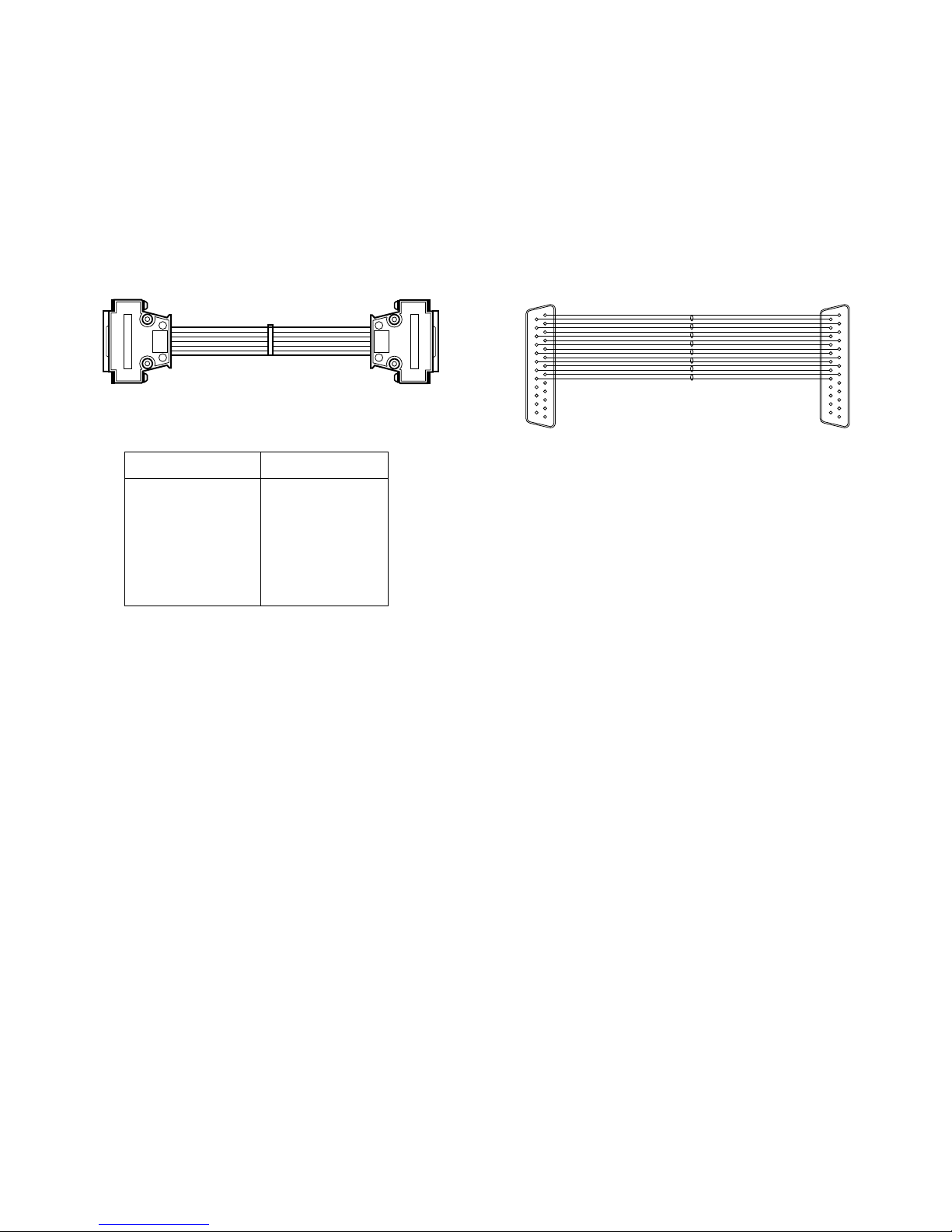
46
WJ-CA85L❑❑ Extension Cable
■ Preface
The WJ-CA85L series is an optional extension cable for connecting between cages. Cables are supplied in seven different
lengths.
■ Appearance
1.0 m
1.0 m
Model Number Cable Length
WJ-CA85L05 0.5 m (1.6 ft)
WJ-CA85L10 1.0 m (3.3 ft)
WJ-CA85L15 1.5 m (4.9 ft)
WJ-CA85L20 2.0 m (6.6 ft)
WJ-CA85L25 2.5 m (8.2 ft)
WJ-CA85L30 3.0 m (9.8 ft)
WJ-CA85L50 5.0 m (16.4 ft)
13
11
25
14
13
25
14
Page 46
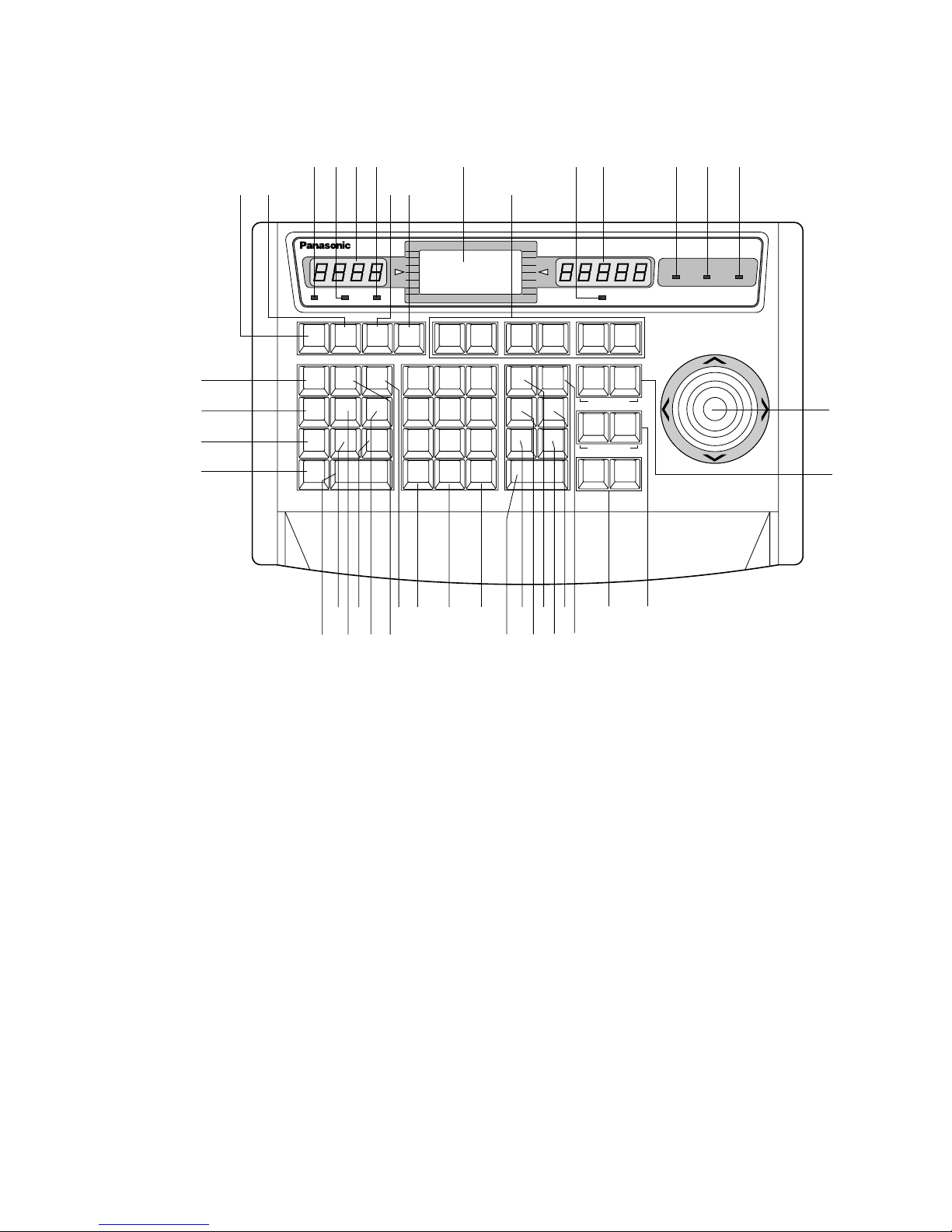
47
WV -CU850 System Controller
■ Appearance
● Front View
ALARM
ACK
RESET
ALL
RESET
ARM
GROUP
PRESET
PREV
S-CTL IDOPE ID
NEXT
GROUP
SEQ
PAUSE STOP
TOUR
SEQ
REV
RUN
FWD
RUN
OSD
F.1 F.2 F. 3
CMENU
OFF
F.4
CMENU
ON
F.5 F.6
CLOSE
IRIS
WIPER
OPEN
NEAR FAR
UP
BUSY
ACK
LOCK
CAMERA
INFORMATION
MONITOR
ALARM LINK OPERATE
DOWN
R
L
WIDE TELE
AUTO FOCUS
ZOOM
MONITOR
LOCK
OSD SERVICE
LOGOUT
AUX1 OFF AUX1 ON
CALL
PRESET
PGM
PRESET
CAM
POSI
DIGITAL
OUT
CAMERA
(ENTER)
CAM ID
VLD S
T&D
ALM S
GEN
SYS S
(
ALARM
)
0
87
DEF OFF
AUTO PAN
DEF ON
MSTA TUS
VLD H
ALL
ALM H
BLK
5964
231
SHIFT
CLEAR
(
ESC
)
EXIT
System Controller WV
–
CU 850
BUSY
AREA
AUX2 OFF AUX2 ON
DEFAULT
FOCUS
VER
CAM
FUNC
q rwe t y u i o !0
!1 !2 !3 !4 !5
!6
!7
!8!9
@0
@1@5@7
@8
@22
@4
@3
@6
#1#2#3#6
@9#4 #0#5
#8
#7
#9
$0
q Alarm Acknowledge indicator (ACK)
Lights up (red) when the activated alarm is acknowledged.
w Monitor Busy indicator (BUSY)
Lights up (red) when you attempt to control a monitor
that is already used by a higher priority operator, or
when a higher priority operator selects the monitor you
are currently operating.
Operations from the System Controller are disabled
until this indicator goes off.
e Monitor LED Display (MONITOR)
Displays the Monitor Number currently controlled.
r Monitor Lock Indicator (LOCK)
Lights (red) to indicate that the currently selected monitor is priority locked, and retains control of a monitor by
an operator.
Pressing the MONITOR key, while holding down the
SHIFT key, will toggle the indicator on and off.
t LCD (Liquid Crystal Display) Display
(INFORMATION)
Displays numeric input, system status, general status,
etc.
y Camera Busy indicator (BUSY)
Lights up (red) when you attempt to control a camera
that is already used by a higher priority operator, or
when a higher priority operator selects the camera you
are currently operating.
Operations from the System Controller are disabled
until this indicator goes off.
u Camera LED Display (CAMERA)
Displays the Camera Number currently controlled.
i Alarm Indicator (ALARM)
Lights (red) to indicate that an alarm condition exists.
To turn off the indicator, select the alarm by pressing
the Numeric and ALARM keys, then press the RESET
key.
Page 47

48
o Link Indicator (LINK)
Is on (green) when communication is established with
the Main CPU.
!0 Operate Indicator (OPERATE)
Is on (green) while the controller’s power is turned on.
!1 Alarm key (ALARM)
This key, in combination with the Numeric keys, is used
to select an alarm. To select an activated alarm, press
the Numeric keys, followed by the ALARM key.
!2 Alarm Acknowledge key (ACK)
Acknowledges an activated alarm.
To acknowledge the activated alarm, first select the
alarm by pressing the Numeric keys, followed by the
ALARM key. Select the desired alarm action number by
pressing the Numeric keys, then press the ACK key.
The ACK indicator will light.
After acknowledging the alarm, press the RESET key to
reset the alarm. The ACK indicator will go off.
!3 Alarm Reset key (RESET)
Cancels an activated alarm.
Press this key to reset an alarm activated in the currently active unit.
Pressing this key while holding down the SHIFT key
cancels all currently activated alarms at a time (ALL
RESET).
Pressing RESET in the Camera Menu will reset the
parameter of a selected item or open the Special
Camera Menu when the cursor is positioned on SPECIAL in the menu. Pressing it while holding down the
SHIFT key will restore all factory default settings.
!4 Alarm Arm key (ARM)
This key, in combination with the Numeric keys and
ALARM key, is used to arm or disarm cameras and
monitor for alarm response. Select an alarm number by
pressing the Numeric keys, followed by the ALARM
key. Then pressing this key repeatedly will enable or
disable the alarm activation with the selected alarm
input.
!5 Function keys (F1 - F6)
These keys provide access to camera attributes and
operating functions.
F1: Reserved for future use.
F2: Reserved for future use.
F3: Pressing F3 while holding down the SHIFT key will
close the Camera Menu on the active monitor
screen (CMENU OFF).
F4: Pressing F4 while holding down the SHIFT key will
open the Camera Menu on the active monitor
screen (CMENU ON).
F5: Reserved for future use.
F6: Pressing this key will select the mode for control-
ling selected camera function (CAM FUNC).
!65 Joystick Controller (L / R / UP / DOWN)
The joystick is used to manually operate the PAN/Tilt
Head, or move the cursor in the Camera Menu on the
active monitor screen.
UP: Upward
DOWN: Downward
L: Left
R: Right
!7 Iris Control keys (IRIS, CLOSE / OPEN)
Close or open the lens iris of cameras equipped with
the specified lens.
When these keys are pressed at the same time, the lens
iris is reset to the factory default setting.
These keys are also used to turn on the camera site
accessories. Pressing the CLOSE key while holding
down the SHIFT key will turn on the housing wiper of the
camera until the keys are released (WIPER).
!8 Focus Control keys (FOCUS, NEAR / FAR)
Adjust the lens focus of cameras equipped with the
specified lens.
Pressing these keys at the same time will automatically
set the lens focus if the specified camera with the auto
focus feature is equipped.
!9 Zoom Control keys (ZOOM, WIDE / TELE)
These keys are used for zooming cameras equipped
with the specified lens.
@0 Area key (AREA)
This key, in combination with the Numeric keys, is used
to change the monitoring area. Access is limited to
super users. Access by regular operators is prohibited.
The function allows users to apply logical numbers to
monitors.
Pressing this key while holding down the SHIFT key will
turn on the user's auxiliary 1 switch of the Receiver
(AUX1 ON).
@1 Program Preset key (PGM PRESET)
This key, in combination with the Numeric keys and
CAMERA (ENTER) key, is used to save a preset position of camera in a system equipped with the specified
cameras.
To save a preset position, move the camera to the position to be preset and select a preset number by pressing the Numeric keys. Hold down this key, then press
the CAMERA (ENTER) key.
Pressing this key while holding down the SHIFT key will
turn on the user's auxiliary 2 switch of the Receiver
(AUX2 ON).
Page 48

49
@2 Digital Output key (DIGITAL OUT)
This key, in combination with the Numeric keys, is used
to select a logical output number and produce a one
shot pulse for activating an assigned event.
Pressing this key while holding down the SHIFT key will
turn on the housing defroster of the camera (DEF ON).
@3 Log-out key (LOGOUT)
This key, in combination with the CAMERA (ENTER)
key, is used to log out from the system.
To prevent a log-out error, press CAMERA (ENTER)
while holding down the LOGOUT key.
Pressing this key while holding down the SHIFT key will
turn off the user's auxiliary 1 switch of the Receiver
(AUX1 OFF).
@4 Call Preset key (CALL PRESET)
This key, in combination with the Numeric keys, is used
to move to a preset position of the selected camera in a
system equipped with the specified cameras.
Pressing this key while holding down the SHIFT key will
turn off the user's auxiliary 2 switch of the Receiver
(AUX2 OFF).
@5 Camera Position key (CAM POSI)
This key, in combination with the Numeric keys, is used
to move the camera to the preset position programmed
in advance in a system equipped with the specified
cameras.
Pressing this key while holding down the SHIFT key will
turn off the housing defroster of the camera (DEF OFF).
@6 Camera / Enter key [CAMERA(ENTER)]
CAMERA: This key is used for camera selection. Press
the desired Numeric keys, then press this key to
select the camera.
ENTER: This key, in combination with the Numeric
keys, is used to enter numeric input, such as operator ID and password.
It is also used to execute the currently highlighted
selection and to enter a submenu of the Camera
Menu.
Pressing CAMERA (ENTER) while holding down the
SHIFT key will activate the auto panning function of the
selected camera (AUTO PAN).
@7 Clear / Escape key [CLEAR (ESC)]
Clear: This key is used to clear numeric input from the
LCD Display.
Escape: This key is used to escape from the currently
highlighted selection and return to the previous
page of the Camera Menu.
This key is also used to exit from alarm selecting mode
to normal operation mode.
@8 Numeric keys (0 - 9)
These keys are used for numeric input into the system
such as the camera and monitor number, sequence
number, preset position, etc.
@9 Shift key (SHIFT)
Pressing this key in combination with keys to which
special functions have been assigned will activate
these functions.
#0 Next key (NEXT)
When a Tour Sequence running in forward direction has
been paused with the Pause key, pressing this key will
move the sequence one frame to the next step (in forward run direction). If the sequence was running in
reverse direction, the key will move the sequence one
frame to the next step (in reverse run direction).
The key is also used to select a camera. Pressing it
while holding down the CAMERA (ENTER) key will
replace the currently selected camera with the next
higher camera number, if the active monitor is in Spot
mode.
Similarly pressing this key while holding down the
MONITOR key will select the next higher monitor number.
When selecting alarms, pressing this key while holding
down the ALARM key will select the next alarm.
Pressing this key while holding down the SHIFT key will
display the software version of the system on the LCD
Display of the controller.
#1 Previous key (PREV)
When a Tour Sequence running in forward direction has
been paused with the Pause key, pressing this key will
move the sequence one frame to the previous step (in
forward run direction). If the sequence was running in
reverse direction, the key will move the sequence one
frame to the previous step (in reverse run direction).
The key is also used to select a camera. Pressing it
while holding down the CAMERA (ENTER) key will
replace the currently selected camera with the next
lower camera number, if the active monitor is in Spot
mode.
Similarly pressing this key while holding down the
MONITOR key will select the next lower monitor number.
When selecting alarms, pressing this key while holding
down the ALARM key will select the previous alarm.
Pressing this key while holding down the SHIFT key will
display the controller ID on the LCD display (S-CTL ID).
#2 Stop key (STOP)
This key is used to end a Tour Sequence that is being
run on the active monitor.
To end a Group sequence, select one of the monitors
that are being run on the sequence, then press this key.
#3 Pause key (PAUSE)
This key is used to pause a Tour or Group Sequence
that is being run on the active monitor.
Page 49

50
#4 Forward Run key (FWD RUN)
This key is used to run a selected Tour Sequence in forward direction on the active monitor.
It also restarts a Tour or Group Sequence forward from
the next step that was previously paused by pressing
the PAUSE key.
#5 Reverse Run key (REV RUN)
This key is used to run a selected Tour Sequence in
reverse direction on the active monitor.
It also restarts a Tour Sequence backward from the
next step that was previously paused by pressing the
PAUSE key.
#6 Monitor key (MONITOR)
This key is used to select a monitor.
To select a monitor, press the corresponding Numeric
keys, followed by the MONITOR key.
Pressing this key, in combination with the Numeric
keys, will display the status and history tables on the
active monitor screen.
#7 Group Preset key (GROUP PRESET)
This key, in combination with the Numeric keys, is used
to activate a previously programmed Group Preset
function.
Pressing this key while holding down the SHIFT key will
display the Operator ID on the LCD display (OPE ID).
#8 Group Sequence key (GROUP SEQ)
This key, in combination with the Numeric keys, is used
to run a Group Sequence forward on the assigned monitors.
#9 Tour Sequence key (TOUR SEQ)
This key, in combination with the Numeric and FWD
RUN (REV RUN) keys, is used to run a Tour Sequence
forward (backward) on the active monitor.
Select the desired tour number by pressing the
Numeric keys. Hold down this key and then press the
FWD RUN (REV RUN) key.
Note: By default, pressing TOUR SEQ after numeric
input will run the selected Tour Sequence forward.
$0 OSD (On-Screen Display) key (OSD)
This key is used to toggle the currently selected display
on and off on the active monitor.
Pressing one of the numeric keys shown below while
holding down the OSD key will toggle the following display items on the active monitor on and off.
1: Clock Display (T & D)
2: Camera Title (CAM ID)
3: General Status (GEN)
5: Monitor Status (MSTATUS)
6: All Displays except clock (ALL)
Page 50
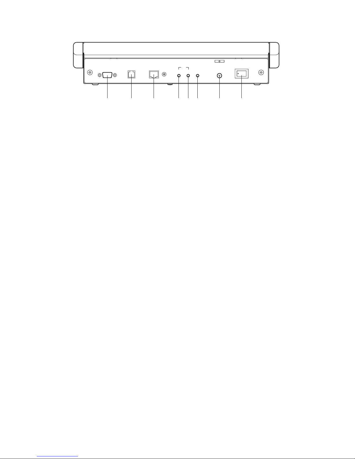
51
● Rear View
$1 Power Switch (POWER, ON / OFF)
This switch turns the power of the System Controller on
and off.
$2 DC12V Input Jack (DC12V IN)
This jack is used to connect the AC Adapter supplied
with the System Controller.
$3 LED Brightness Control (LED BRIGHT)
Adjusts the brightness of the monitor and camera LED
display.
$4 LCD Brightness Control (LCD BRIGHT)
Adjusts the back light brightness of the LCD.
$5 LCD Contrast Control (LCD CONTRAST)
Adjusts the contrast of the characters displayed on the
LCD.
$6 Ethernet Port (ETHERNET)
Exchanges control data with the Central Processing
Unit (CPU) via Ethernet.
$7 Data Port (DATA)
Reserved for future use.
$8 RS-232C Port (RS-232C)
This port is used only for factory tests.
RS–232C DATA
ETHERNET
CONTRAST BRIGHT BRIGHT
DC12V IN
ON OFF
POWER
LEDLCD
$1$2$3$4$5$6$7$8
Page 51
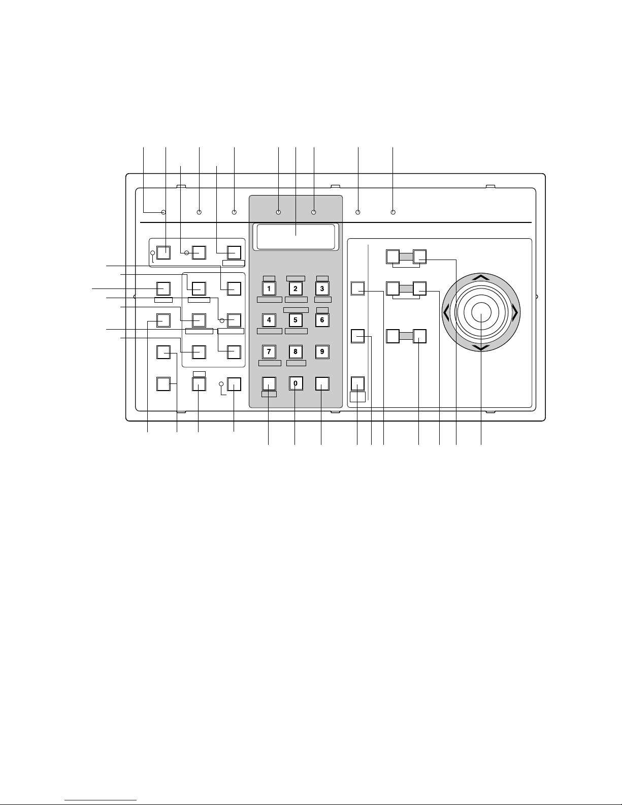
52
WV -CU350 System Controller
■ Appearance
The System controller comes with three templates for use with the Matrix Switcher or Video Multiplexer. Make sure to place the
template for the Matrix Switcher (System 850) on the controller.
● Front View
q Operate indicator (OPERATE)
Is on (green) while the controller’s power is turned on.
w Link indicator (LINK)
Is on (green) when communication is established with
the Main CPU.
e Alarm indicator (ALARM)
Lights (red) to indicate that an alarm condition exists.
To turn off the indicator, select the alarm by pressing
the Numeric and ALARM buttons, then press the RESET
button.
r Monitor indicator (MONITOR)
Is on (orange) when the monitor number is displayed on
the LED Display.
t LED Display
Displays the number of monitors and cameras currently
controlled.
It also displays numeric input and error status, etc.
y Camera indicator (CAMERA)
Is on (orange) when the camera number is displayed
on the LED Display.
u Busy indicator (BUSY)
Lights up (red) when you attempt to control a monitor
(or camera) that is already used by a higher priority
operator, or when the higher priority operator selects
the camera or monitor you are currently operating.
Operations from the System Controller are disabled
until this indicator goes off.
OPERATE LINK ALARM MONITOR CAMERA BUSY PROHIBITED
PROGRAM
PRESET
IRIS
System Controller WV-CU
350
For Matrix Switcher (System 850
)
OPENCLOSE
AUTO IRIS
CALL
PRESET
AUX1 OFF
ALM S
CAM IDT&D
AUX1 ON
VLD S
RESETACK
NEXTPREV
S-CTL ID
STOPPAUSE
CAM MENU ONCAM MENU OFF
TOUR
SEQ
GROUP
SEQ
MONITOR
LOCK
OSD SERVICE
CAM FUNC
OSD
ALARM
DISARM
ALL RESET
OPE ID
GROUP PRESET
LOG OUT
F1
F2
GEN
WIPER
SYS S
AUX2 OFF
ALM H
MON STATUS
AUX2 ON
VDL H
ALL
SHIFT BLK EXIT
CLEAR
(
ESC
)
DEF OFF DEF ON
CAMERA
(
ENTER
)
AUTO
PAN
FOCUS
FARNEAR
AUTO FOCUS
ZOOM
DOWN
UP
RL
TELEWIDE
qwer y uti
!6!7
@2
@4
@5
@8
@6
@7
@3
#1@9 #0
#2
!8
@1@0
o!0!1!2!3!4!5
!9
Page 52

53
i Prohibited indicator (PROHIBITED)
This indicator (red) lights up for 3 seconds when an
attempt is made to gain access to a function that is prohibited by the partition.
o Joystick Controller (UP / DOWN / L / R)
The joystick is used to manually operate the Pan / Tilt
Head, or move the cursor in the Camera Menu on the
active monitor screen.
UP: Upward
DOWN: Downward
L: Left
R: Right
!0 Iris buttons (IRIS, CLOSE / OPEN)
Closes or opens the lens iris of cameras equipped with
the specified lens.
When these buttons are pressed at the same time, the
lens iris is reset to the factory default setting.
!1 Focus buttons (FOCUS, NEAR / FAR)
Adjusts the lens focus of cameras equipped with the
specified lens.
When these buttons are pressed at the same time, the
lens focus is set automatically if the specified camera
with the auto focus feature is equipped.
!2 Zoom buttons (ZOOM, WIDE / TELE)
These buttons are used for zooming cameras equipped
with the specified lens.
!3 Program Preset button (PROGRAM PRESET)
This button, in combination with the Numeric buttons
and CAMERA (ENTER) button, is used to save a preset
position of the camera in a system equipped with the
specified cameras.
To save a preset position, move the camera to the position to be preset and select a preset number by pressing the Numeric buttons. Hold down the PROGRAM
PRESET button, then press the CAMERA (ENTER) button.
!4 Call Preset button (CALL PRESET)
This button, in combination with the Numeric buttons, is
used to move to a preset position of the selected camera in a system equipped with the specified cameras.
!5 Camera / Enter button [CAMERA (ENTER)]
CAMERA: This button is used for camera selection.
Select a camera by pressing the corresponding
Numeric buttons, followed by the CAMERA (ENTER)
button.
ENTER: This button, in combination with the Numeric
buttons, is used to enter numeric input, such as
operator ID and password.
It is also used to execute the currently highlighted
selection and enter a submenu of the Camera
Menu.
Pressing CAMERA (ENTER) while holding down the
SHIFT button will activate the auto panning function of
the selected camera (AUTO PAN).
!6 Clear / Escape button [CLEAR (ESC)]
Clear: This button is used to clear numeric input from
the LED Display.
Escape: This button is used to escape from the current-
ly highlighted selection and return to the previous
page of the Camera Menu.
This button is also used to exit from alarm selecting
mode to normal operation mode.
!7 Numeric buttons (0 - 9)
These buttons are used for numeric input into the system such as the camera and monitor number,
sequence number, preset position, etc..
Pressing the buttons shown below while holding down
the SHIFT button will select special functions.
1: Turns off the user auxiliary 1 switch of the receiver.
(AUX1 OFF)
2: Turn on the user auxiliary 1 switch of the receiver.
(AUX1 ON)
3: Turns on the housing wiper of the camera until
these buttons are released. (WIPER)
4: Turns off the user auxiliary 2 switch of the receiver.
(AUX2 OFF)
5: Turns on the user auxiliary 2 switch of the receiver.
(AUX2 ON)
7: Turns off the housing defroster of the camera. (DEF
OFF)
8: Turns on the housing defroster of the camera. (DEF
ON)
!8 Shift button (SHIFT)
Pressing this button in combination with buttons to
which special functions have been assigned will activate these functions.
!9 Alarm button (ALARM)
This button, in combination with the Numeric buttons, is
used to select an alarm. To select an activated alarm,
press the Numeric buttons, followed by the ALARM button.
This button is also used to arm or disarm cameras and
monitor for alarm response. Select an alarm number by
pressing the Numeric buttons, follqwed by the ALARM
button. Then pressing this button repeatedly will arm or
disarm the active monitor with the selected alarm. The
indicator lights to indicate that the selected alarm is disarmed.
@0 Alarm Acknowledge button (ACK)
Acknowledges an activated alarm.
To acknowledge the activated alarm, first select the
alarm by pressing the Numeric buttons, followed by the
ALARM button. Select the desired alarm action number
by pressing the Numeric buttons, then press the ACK
button. The indicator will light.
After acknowledging the alarm, press the RESET button
to reset the alarm. The ACK indicator will go off.
Page 53

54
@1 Alarm Reset button (RESET)
Cancels an activated alarm.
Press this button to reset an alarm activated in the currently active unit.
Pressing this button while holding down the SHIFT button cancels all currently activated alarms at a time (ALL
RESET).
Pressing RESET in the Camera Menu will reset the
parameter of a selected item or open the Special
Camera Menu when the cursor is positioned on SPECIAL in the menu. Pressing it while holding down the
SHIFT button will restore all factory default settings.
@2 Next button (NEXT)
This button is used to move a Tour Sequence one step
forward from the step that was previously paused on
the active monitor by pressing the PAUSE button.
The button is also used to select a camera. Pressing
NEXT while holding down the CAMERA (ENTER) button
will replace the currently selected camera with the next
higher camera number, if the active monitor is in Spot
mode.
Similarly pressing NEXT while holding down the MONITOR button will select the next higher monitor number.
When selecting alarms, pressing NEXT while holding
down the ALARM button will select the next alarm.
@3 Previous button (PREV)
This button is used to move a Tour Sequence one step
backward from the step that was previously paused on
the active monitor by pressing the PAUSE button.
This button is also used to select a camera. Pressing
PREV while holding down the CAMERA (ENTER) button
will replace the currently selected camera with the next
lower camera number, if the active monitor is in Spot
mode.
Similarly pressing PREV while holding down the MONITOR button will select the next lower monitor number.
When selecting alarms, pressing PREV while holding
down the ALARM button will select the previous alarm.
Pressing this button while holding down the SHIFT button will display the Controller ID number on the LED
Display for about 3 seconds (S-CTL ID).
@4 Stop button (STOP)
This button is used to end a Tour Sequence that is
being run on the active monitor.
To end a Group sequence, select one of the monitors
that are being run on the selected sequence, then
press this button.
Pressing STOP while holding down the SHIFT button
will open the Camera Menu on the active monitor. The
STOP indicator will light. (CAM MENU ON)
@5 Pause button (PAUSE)
This button is used to pause a Tour or Group Sequence
that is being run on the active monitor.
Pressing PAUSE while holding down the SHIFT button
will close the Camera Menu on the active monitor. The
STOP indicator will go off. (CAM MENU OFF)
@6 Tour Sequence button (TOUR SEQ)
This button, in combination with the Numeric buttons, is
used to run a Tour Sequence on the active monitor.
Pressing TOUR SEQ will restart a forward sequence
from the next step that was previously paused by
pressing the PAUSE button.
@7 Group Sequence button (GROUP SEQ)
This button, in combination with the Numeric buttons, is
used to run a Group Sequence on the assigned monitors.
Pressing GROUP SEQ will restart a forward sequence
from the next step that was previously paused by
pressing the PAUSE button.
@8 Group Preset button (GROUP PRESET)
This button, in combination with the Numeric buttons, is
used to activate a previously programmed Group
Preset function.
Pressing This button while holding down the SHIFT button will display the Operator ID number on the LED
Display for about 3 seconds (OPE ID).
@9 Log Out button (LOGOUT)
This button, in combination with the CAMERA (ENTER)
button, is used to log out from the system.
To prevent a log-out error, press CAMERA (ENTER)
while holding down the LOGOUT button.
#0 Function buttons (F1, F2)
These buttons provide access to camera attributes and
operating functions.
F1: Reserved for future use.
F2: Pressing this button will select the mode for control-
ling selected camera function (CAM FUNC).
#1 OSD (On-Screen Display) button (OSD)
This button is used to toggle the currently selected display on and off on the active monitor.
Pressing the numeric buttons shown below while holding down the OSD button will toggle the following display items on the active monitor on and off.
1: Clock Display (T&D)
2: Camera Title Display (CAM ID)
3: General Status Display (GEN)
5: Monitor Status Display (MON STATUS)
6: All Displays except clock (ALL)
#2 Monitor button (MONITOR)
This button is used to select a monitor.
To select a monitor, press the corresponding Numeric
buttons, followed by the MONITOR button.
Pressing this button while holding down the SHIFT button will toggle the indicator on and off. The indicator
lights to indicate that the currently selected monitor is
priority locked, and retains control of a monitor by an
operator.
This button, in combination with the Numeric buttons, is
also used to display the status and history tables on the
active monitor screen.
Page 54
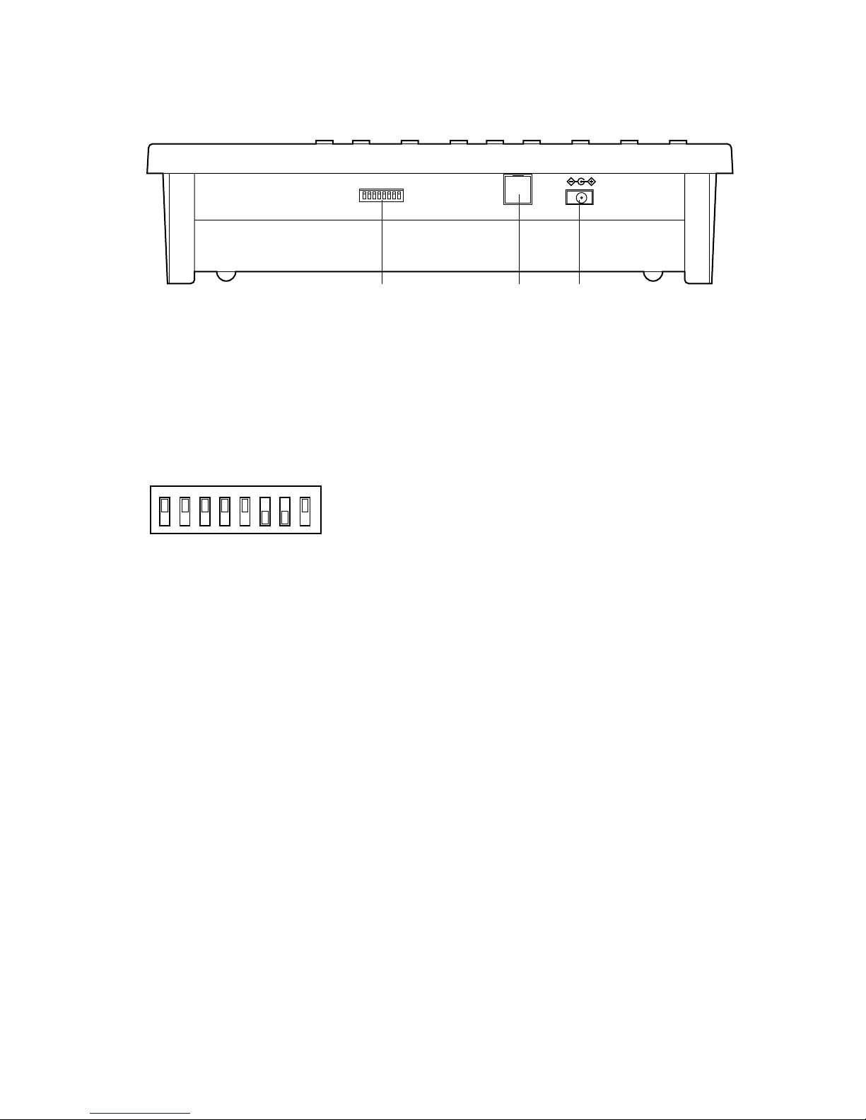
55
12345678
OFF
ON
● Rear View
MODE
DATE OUT DC 9V IN
$1 $2 $3
$1 Mode Selection Switches (MODE)
These switches are used to select the mode of the
System Controller.
Set the switches to the required positions shown below.
Caution: Turn the controller’s power off when changing
the DIP switch setting.
$2 Data Output Port (DATA OUT)
Exchanges control data with the Central Processing
Unit (CPU).
$3 DC 9V Input Jack (DC 9V IN)
This jack is used to connect the AC Adapter supplied
with the System Controller.
Page 55
57
INSTALLATIONS AND
SYSTEM CONNECTIONS
Page 56
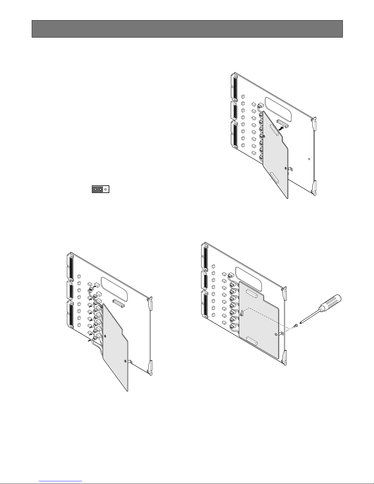
58
INSTALLATIONS
The installation described below should be made by
qualified service personnel or system installers and
should conform to all local codes.
INSTALLA TION OF SYSTEM
COMPONENTS
■ Installing a Character Board
If the WJ-PB85D01 Character Board is installed on the WJPB85X08 Camera Input Board, follow the procedure shown
below.
1. Position jumper connectors (CN103, CN203, CN303,
CN403, CN503, CN603, CN703, and CN803) on the
Camera Input board as shown below.
CN103
13
2. Insert the connectors of the Character board into the
specified connectors (CN102, CN202, CN302, CN402,
CN502, CN602, CN702, and CN802) on the Camera
Input board.
3. Place the Character board on the Camera Input board
and plug in the boards.
4. Fix both boards with the two supplied screws (M3x6)
as shown below.
Page 57
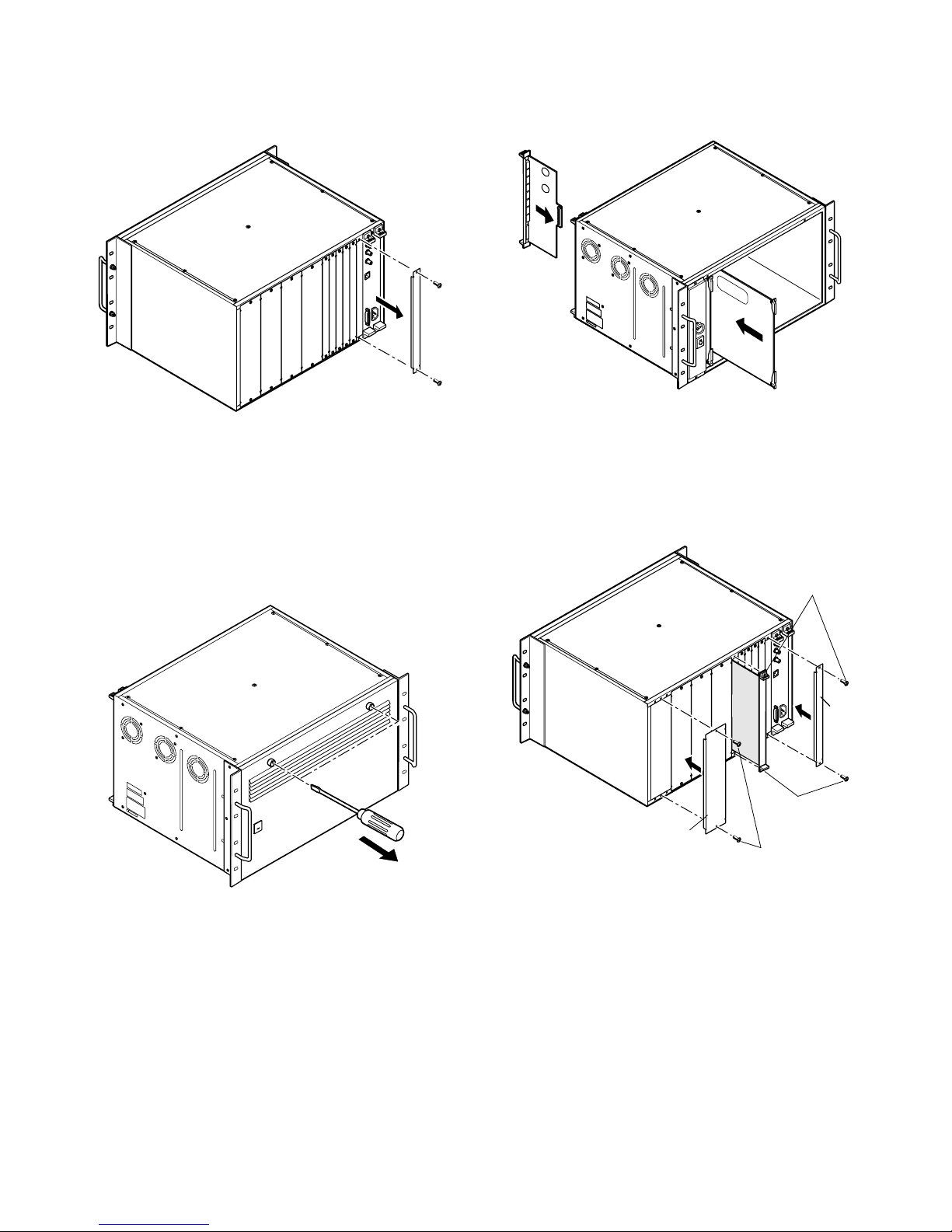
59
■ Installing Additional Extension Boards
1. Remove the screws from the rear panel(s) of the WJSX850 Matrix Switcher Card Cage.
2. Remove the rear panel(s).
3. Remove the front panel of the cage by removing the
two screws on the panel shown below when installing
the boards into the WJ-SX850 Card cage.
4. Place the Boards into the specified positions in the
front or rear of the Cage by sliding them along the
board guides as shown below.
5. Make sure to push in the Boards until they are seated
firmly.
6. Secure the rear board by tightening the two screws on
the board.
Board
Tighten screws
Tighten screws
Rear
panel
Rear
panel
Tighten screws
7. Close open spaces on the rear of the Cage with the
supplied rear panel(s).
8. Close the front of the cage by fixing the front panel.
Page 58
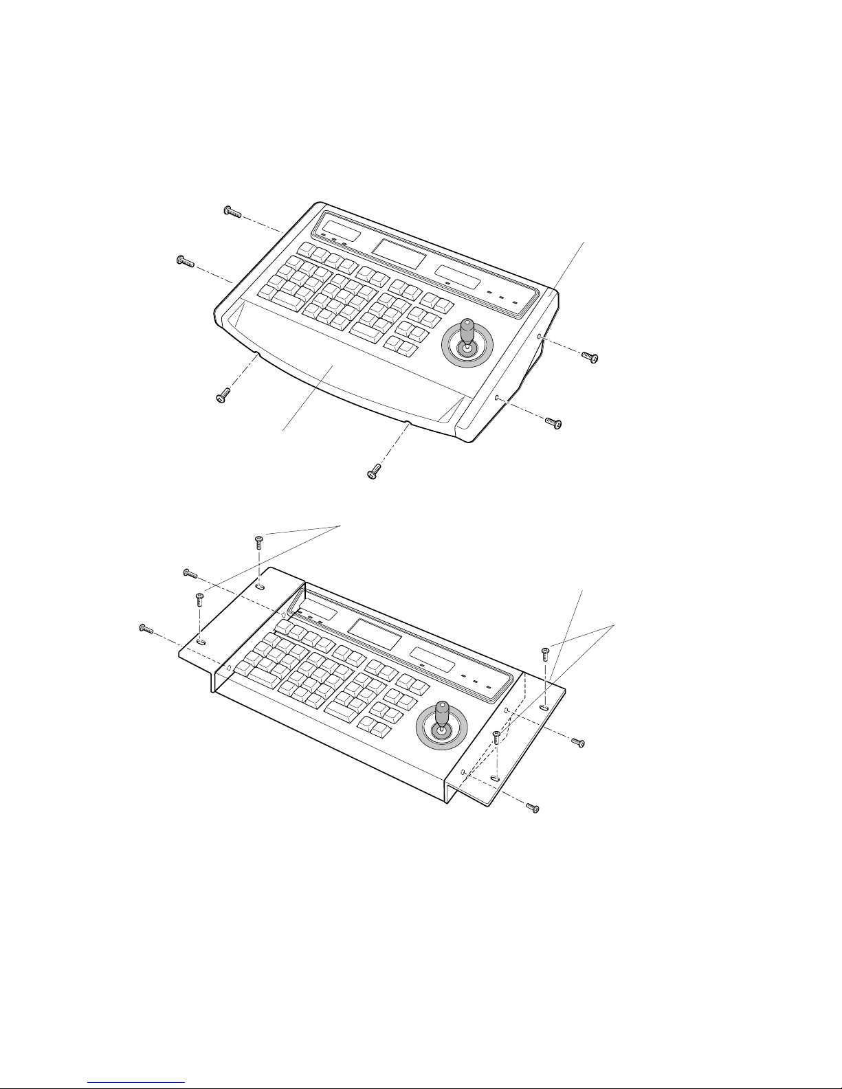
60
■ WV-CU850 System Controller
● Replacing the Side Panels with the optional WV-Q62 Rack Mounting Brackets
1. Remove both the left and right side panels of the System Controller by removing four screws.
2. Remove the palm-rest located on the front of the System Controller by removing two screws.
3. Place the Rack Mounting Brackets on both sides of the System Controller and tighten with the four supplied screws.
4. Install the System Controller with Rack Mounting Brackets in the rack by using four screws (not included).
Remove screws.
Tighten screws.
Rack Mounting Bracket
Palm-rest
Side Panel
Rack Mounting Screws
Rack Mounting Screws
Page 59
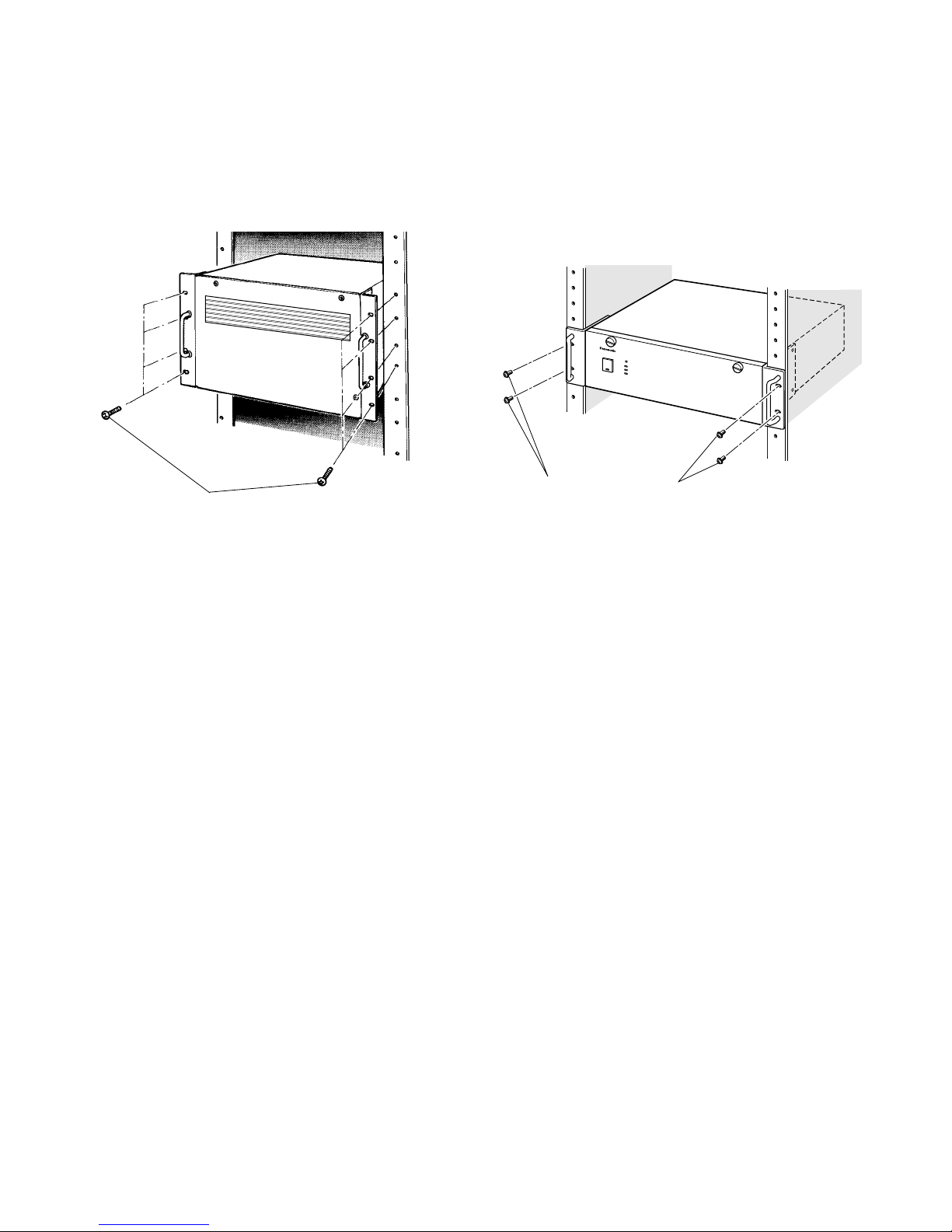
61
■ WJ-SX850 Matrix Switcher Card Cage
● Mounting into the Rack
1. Remove the four rubber feet by removing four screws
from the bottom of the Matrix Switcher.
2. Install the Matrix Switcher in the rack securing it with
eight screws (not included).
Rack Mounting Screws
Cautions:
• The cooling fans inside the card cage are subject
to wear and need to be replaced periodically.
• Do not block the ventilation opening or slots on the
cover to prevent the temperature from rising inside
the unit.
Always keep the temperature in the rack within
45˚C (113˚F).
• If the rack is subject to vibration, secure the rear of
the unit to the rack using additional mounting
brackets (procured locally).
■ WJ-MPU850 Central Processing Unit
WJ-MPU855 Central Processing Unit
● Mounting into the Rack
1. Remove the four rubber feet by removing four screws
from the bottom of the CPU.
2. Install the CPU in the rack securing it with four screws
(not included).
C
o
ntro
l Proc
ess
in
g U
nit W
J-M
P
U
850
Rack Mounting Screws
Cautions:
• The cooling fans inside the CPU are subject to
wear and need to be replaced periodically.
• Do not block the ventilation opening or slots on the
cover to prevent the temperature from rising inside
the unit.
Always keep the temperature in the rack within
45˚C (113˚F).
• If the rack is subject to vibration, secure the rear of
the unit to the rack using additional mounting
brackets (procured locally).
Page 60
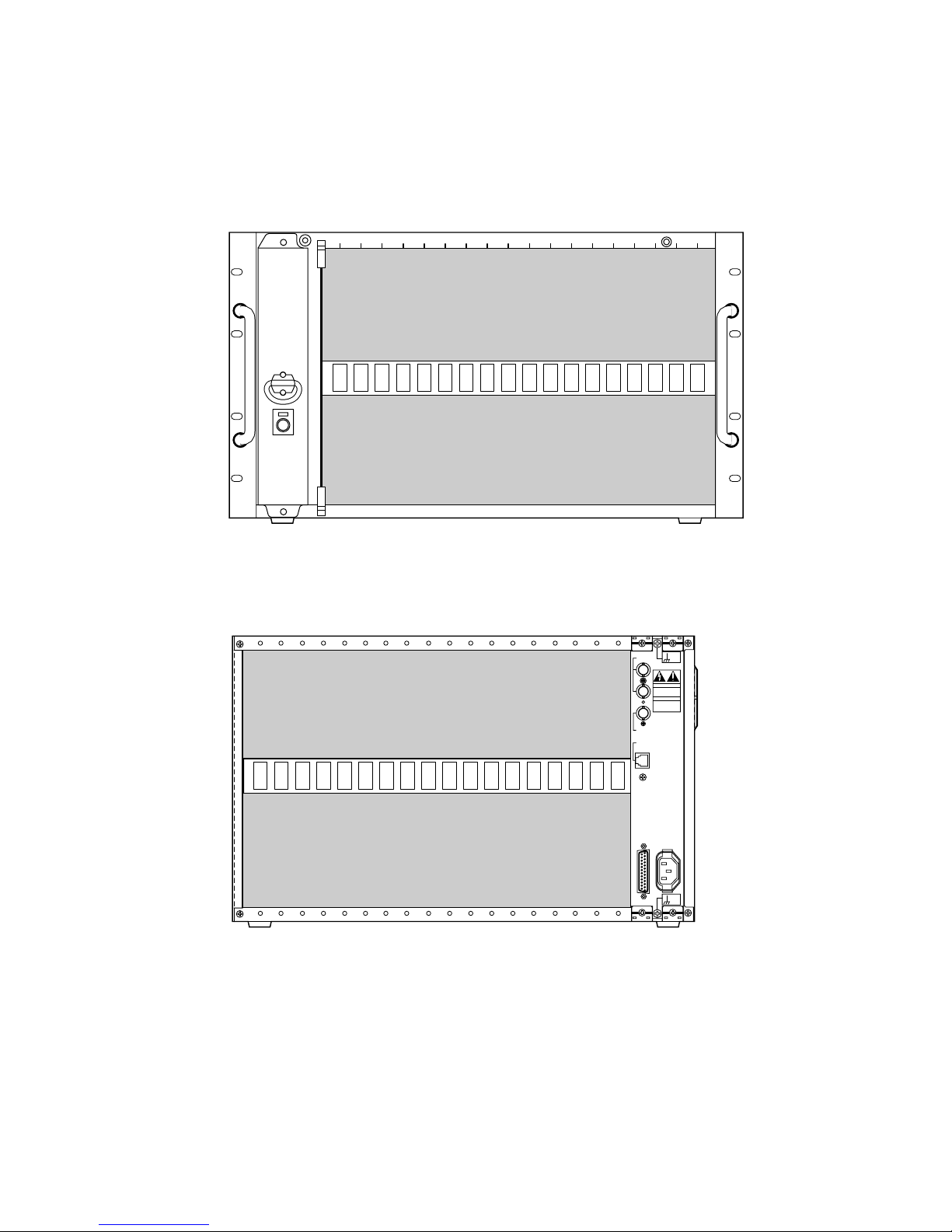
62
BOARD SELECTION FOR SYSTEM EXPANSION
The WJ-SX850 Card Cage has 18 slots.
Install the optional extension boards in the WJ-SX850 Card Cage depending on the number of camera inputs and monitor outputs required.
Front View
1 2 3 4 5 6 7 8 9 10 11 12 13 14 15 16 17 18
CPU
DO NOT OPEN
RISK OF ELECTRIC SHOCK.
SIGNAL
GND
SIGNAL
GND
RS-232C
CAUTION
ATTENTION
NE PAS OUVRIR
RISQUE DE CHOCS
ELECTROUES
VS / VD
IN
OUT
VD OUT
ETHERNET
AC IN
18 17 16 15 14 13 12 11 10 9 8 7 6 5 4 3 2 1
Rear View
Page 61
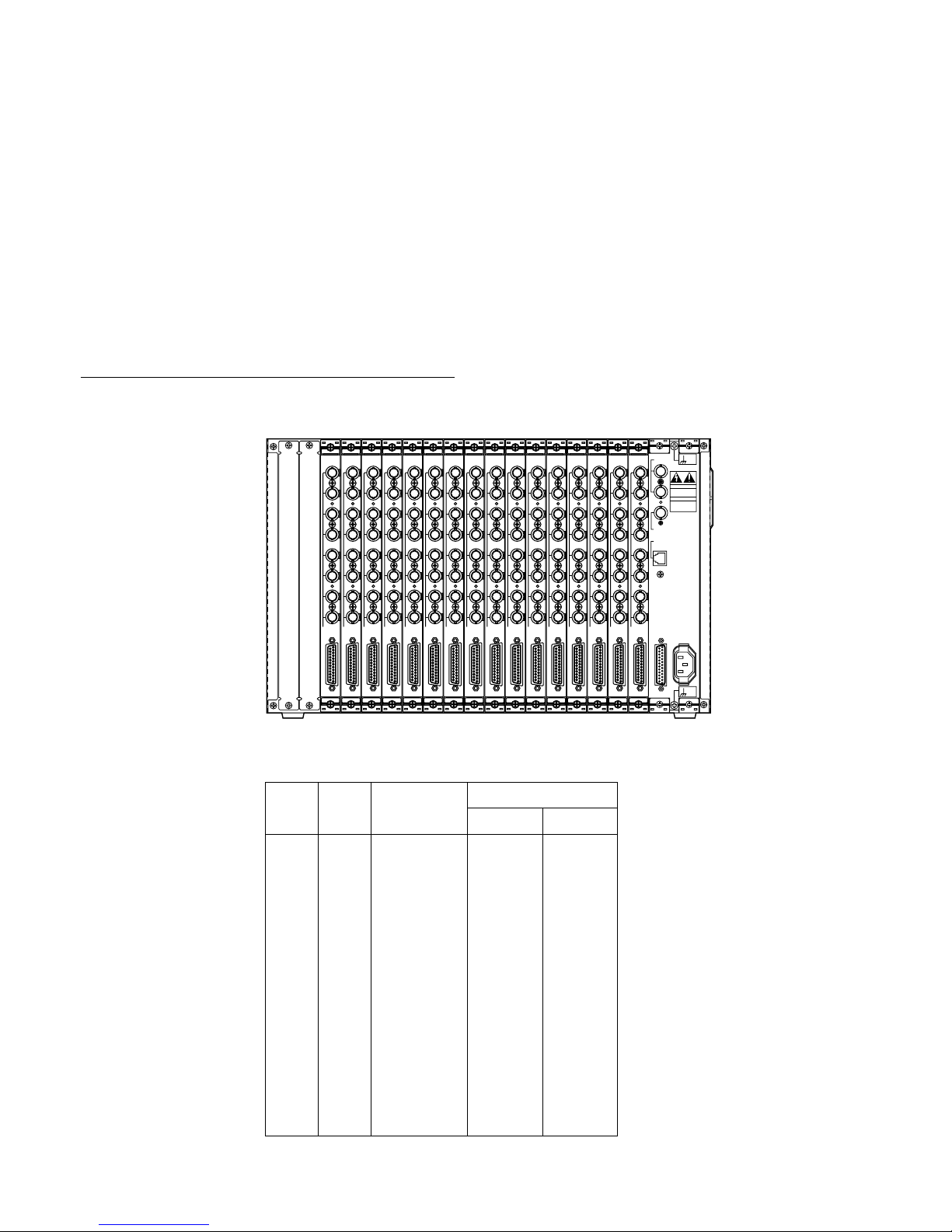
63
■ Camera Control Bay
The Camera Control Bay is a newly designed density combination unit which controls camera site and video receiving.
A single camera control cage (MXCONT) allows for flexible control of up to 128 cameras. A maximum of 8 192 cameras can
be connected to several camera control cages (MXCONTs).
Two types of interface boards, an 8-channel Camera Input Board and an 8-channel RS-485 Data Board, are available to meet
different requirements with regard to the type of video and data connections between cameras and camera site devices.
The MXCONT is composed of the following individual functional modules:
• Card Cage WJ-SX850
• 8ch Camera Input Board WJ-PB85X08
• Character Board WJ-PB85D01
• 8ch RS-485 Data Board WJ-PB85R08
• 8ch Loop-Through Board WJ-PB85Y08
● Application 1
An MXCONT fully equipped for 128 cameras (Data Multiplexed Cameras) contains the following:
Description Model No. Qty.
Card Cage WJ-SX850 1
Camera Input Board WJ-PB85X08 16
Install the Camera Input Boards into the slots (1 to 16) in
the Card Cage as shown below.
1
2
3
4
5
6
7
8
CAMERA IN
VIDEO OUT
CAMERA
1
2
3
4
5
6
7
8
CAMERA IN
VIDEO OUT
CAMERA
1
2
3
4
5
6
7
8
CAMERA IN
VIDEO OUT
CAMERA
1
2
3
4
5
6
7
8
CAMERA IN
VIDEO OUT
CAMERA
1
2
3
4
5
6
7
8
CAMERA IN
VIDEO OUT
CAMERA
1
2
3
4
5
6
7
8
CAMERA IN
VIDEO OUT
CAMERA
1
2
3
4
5
6
7
8
CAMERA IN
VIDEO OUT
CAMERA
1
2
3
4
5
6
7
8
CAMERA IN
VIDEO OUT
CAMERA
1
2
3
4
5
6
7
8
CAMERA IN
VIDEO OUT
CAMERA
1
2
3
4
5
6
7
8
CAMERA IN
VIDEO OUT
CAMERA
1
2
3
4
5
6
7
8
CAMERA IN
VIDEO OUT
CAMERA
1
2
3
4
5
6
7
8
CAMERA IN
VIDEO OUT
CAMERA
1
2
3
4
5
6
7
8
CAMERA IN
VIDEO OUT
CAMERA
1
2
3
4
5
6
7
8
CAMERA IN
VIDEO OUT
CAMERA
1
2
3
4
5
6
7
8
CAMERA IN
VIDEO OUT
CAMERA
1
2
3
4
5
6
7
8
CAMERA IN
VIDEO OUT
CAMERA
DO NOT OPEN
RISK OF ELECTRIC SHOCK.
SIGNAL
GND
SIGNAL
GND
RS-232C
CAUTION
ATTENTION
NE PAS OUVRIR
RISQUE DE CHOCS
ELECTROUES
VS / VD
IN
OUT
VD OUT
ETHERNET
AC IN
[Board Setting]
• Set switches (SW4 and SW5) on the WJ-PB85X08 Camera Input Boards to designate the board numbers as shown in the
following table.
Slot
No.
Camera
Input
SW Positions
SW5 SW4
1
2
3
4
5
6
7
8
9
10
11
12
13
14
15
16
Board
No.
1
2
3
4
5
6
7
8
9
10
11
12
13
14
15
16
0
0
0
0
0
0
0
0
0
0
0
0
0
0
0
0
0
1
2
3
4
5
6
7
8
9
A
B
C
D
E
F
1 - 8
9 - 16
17 - 24
25 - 32
33 - 40
41 - 48
49 - 56
57 - 64
65 - 72
73 - 80
81 - 88
89 - 96
97 - 104
105 - 112
113 - 120
121 - 128
For other DIP switch settings, refer to the Board Setting of the individual board.
Page 62
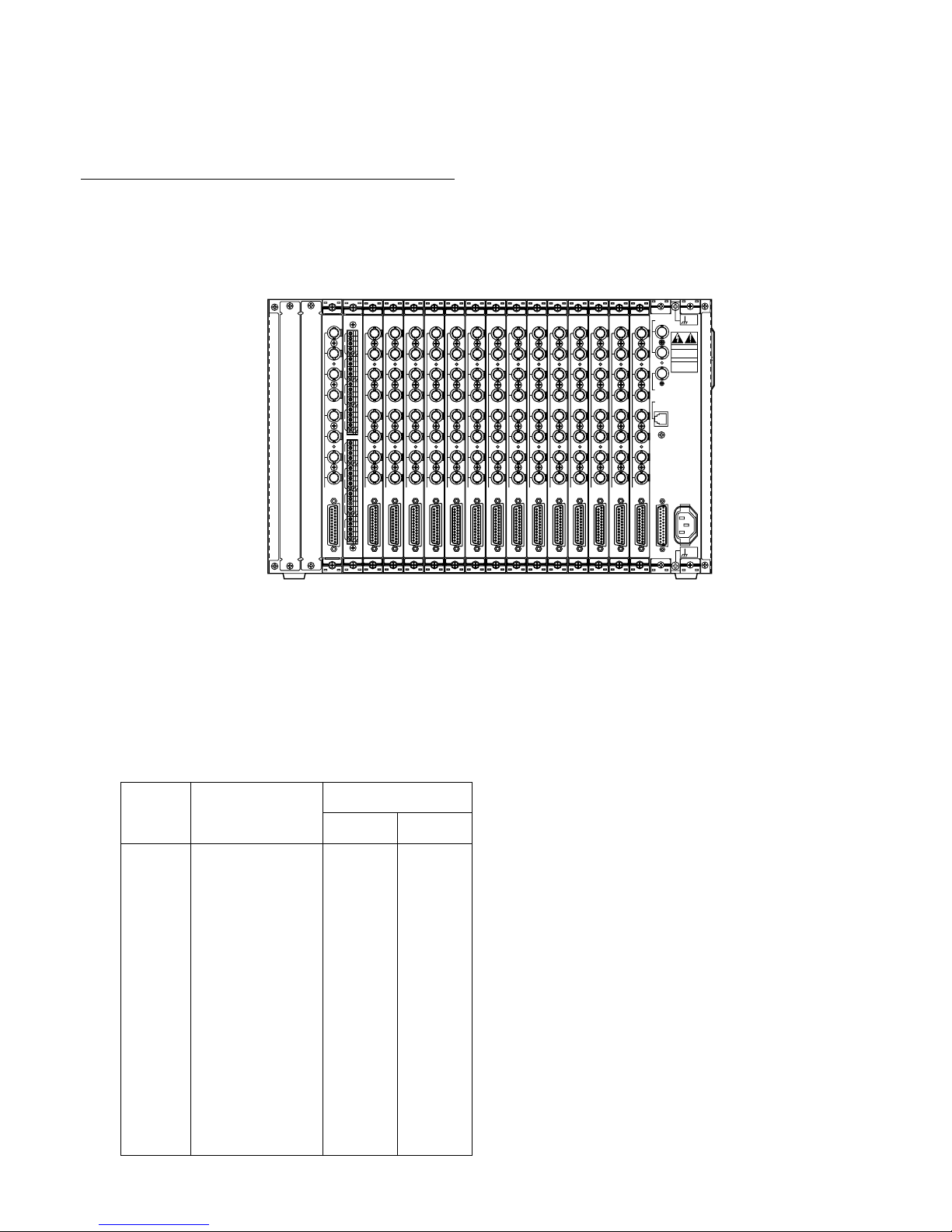
64
● Application 2
If both Data Multiplexed Cameras and RS-485 Cameras are used in the system, install extension boards as shown below.
In the example, multiplexed cameras at Camera Inputs (113 - 128) have been replaced with RS-485 cameras.
Description Model No. Qty.
Card Cage WJ-SX850 1
Camera Input Board WJ-PB85X08 14
RS-485 Data Board WJ-PB85R08 1
Loop-Through Board WJ-PB85Y08 1
Install the Camera Input Boards into the slots (1 to 14)
in the Card Cage, the RS-485 Data Board into slot 15,
and the Loop-Through Board into slot 16 as shown
below.
1
2
3
4
5
6
7
8
CAMERA IN
VIDEO OUT
CAMERA
1
2
3
4
5
6
7
8
CAMERA IN
VIDEO OUT
CAMERA
1
2
3
4
5
6
7
8
CAMERA IN
VIDEO OUT
CAMERA
1
2
3
4
5
6
7
8
CAMERA IN
VIDEO OUT
CAMERA
1
2
3
4
5
6
7
8
CAMERA IN
VIDEO OUT
CAMERA
1
2
3
4
5
6
7
8
CAMERA IN
VIDEO OUT
CAMERA
1
2
3
4
5
6
7
8
CAMERA IN
VIDEO OUT
CAMERA
1
2
3
4
5
6
7
8
CAMERA IN
VIDEO OUT
CAMERA
1
2
3
4
5
6
7
8
CAMERA IN
VIDEO OUT
CAMERA
1
2
3
4
5
6
7
8
CAMERA IN
VIDEO OUT
CAMERA
1
2
3
4
5
6
7
8
CAMERA IN
VIDEO OUT
CAMERA
1
2
3
4
5
6
7
8
CAMERA IN
VIDEO OUT
CAMERA
1
2
3
4
5
6
7
8
CAMERA IN
VIDEO OUT
CAMERA
1
2
3
4
5
6
7
8
CAMERA IN
VIDEO OUT
CAMERA
DO NOT OPEN
RISK OF ELECTRIC SHOCK.
SIGNAL
GND
SIGNAL
GND
RS-232C
CAUTION
ATTENTION
NE PAS OUVRIR
RISQUE DE CHOCS
ELECTROUES
VS / VD
IN
OUT
VD OUT
ETHERNET
AC IN
1
2
3
4
5
6
7
8
IN/OUT
IN/OUT
THRU
RS485
A
T
B
A
R
B
G
A
T
B
A
R
B
G
A
T
B
A
R
B
G
A
T
B
A
R
B
G
1
2
3
4
A
T
B
A
R
B
G
A
T
B
A
R
B
G
A
T
B
A
R
B
G
A
T
B
A
R
B
G
5
6
7
8
Caution: Do not install Camera Input Boards and the RS-485 Data Boards into slots 17 and 18. These are reserved for
installing Crosspoint Output Boards.
[Board Setting]
• Set switches (SW4 and SW5) on the WJ-PB85X08 Camera Input Boards to designate the board numbers as shown in the
table for Application 1.
• Set switches (SW1 and SW2) on the WJ-PB85R08 RS-485 Data Boards to designate the board number as 15 in the table
shown below.
Board
No.
Data I/O
SW Positions
SW2 SW1
1
2
3
4
5
6
7
8
9
10
11
12
13
14
15
16
0
0
0
0
0
0
0
0
0
0
0
0
0
0
0
0
0
1
2
3
4
5
6
7
8
9
A
B
C
D
E
F
1 - 8
9 - 16
17 - 24
25 - 32
33 - 40
41 - 48
49 - 56
57 - 64
65 - 72
73 - 80
81 - 88
89 - 96
97 - 104
105 - 112
113 - 120
121 - 128
For other DIP switch settings, refer to the Board
Setting of the individual board.
Page 63
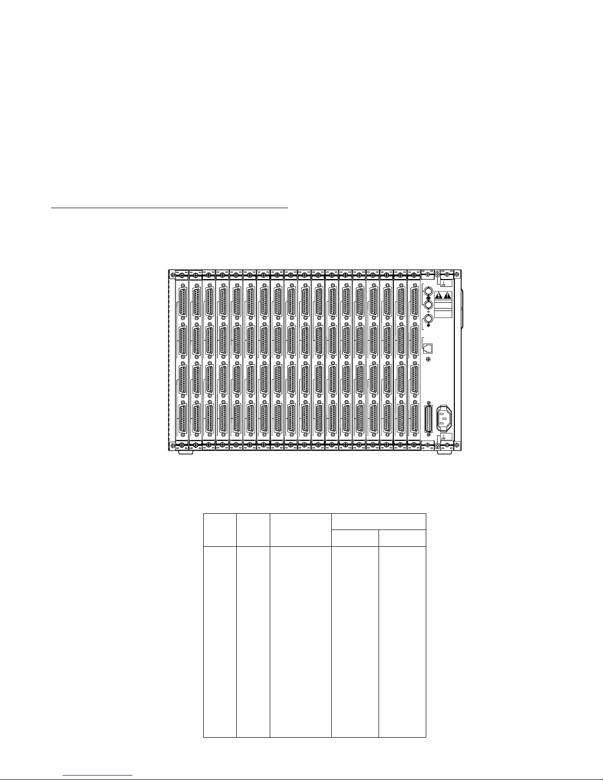
65
■ Crosspoint Bay
The Crosspoint Bay is a scalable distributed space-division switch.
The basic card cage (MXSW) has a maximum capacity of 256 inputs and 32 outputs. Multiple MXSWs can be combined to
support up to 8 192 inputs and 1 024 outputs.
The MXSW is composed of the following individual functional modules:
• Card cage WJ-SX850
• 16ch Crosspoint Input Board WJ-PB85C16
• 16ch Crosspoint Output Board WJ-PB85M16
● Application
An MXSW fully equipped for 256 inputs and 32 outputs contains the following:
Description Model No. Qty.
Card Cage WJ-SX850 1
Crosspoint Input Board WJ-PB85C16 16
Crosspoint Output Board WJ-PB85M16 2
Install the Crosspoint Input Boards into the slots (1 to
16) in the Card Cage and the Crosspoint Output
Boards into slots 17 and 18 in the Card Cage as shown
below.
1
2
VIDEO IN
1
2
VIDEO OUT
INPUT
1
2
VIDEO IN
1
2
VIDEO OUT
INPUT
1
2
VIDEO IN
1
2
VIDEO OUT
INPUT
1
2
VIDEO IN
1
2
VIDEO OUT
INPUT
1
2
VIDEO IN
1
2
VIDEO OUT
INPUT
1
2
VIDEO IN
1
2
VIDEO OUT
INPUT
1
2
VIDEO IN
1
2
VIDEO OUT
INPUT
1
2
VIDEO IN
1
2
VIDEO OUT
INPUT
1
2
VIDEO IN
1
2
VIDEO OUT
INPUT
1
2
VIDEO IN
1
2
VIDEO OUT
INPUT
1
2
VIDEO IN
1
2
VIDEO OUT
INPUT
1
2
VIDEO IN
1
2
VIDEO OUT
INPUT
1
2
VIDEO IN
1
2
VIDEO OUT
INPUT
1
2
VIDEO IN
1
2
VIDEO OUT
INPUT
1
2
VIDEO IN
1
2
VIDEO OUT
INPUT
1
2
VIDEO IN
1
2
VIDEO OUT
INPUT
1
2
VIDEO IN
1
2
VIDEO OUT
OUTPUT
1
2
VIDEO IN
1
2
VIDEO OUT
OUTPUT
DO NOT OPEN
RISK OF ELECTRIC SHOCK.
SIGNAL
GND
SIGNAL
GND
RS-232C
CAUTION
ATTENTION
NE PAS OUVRIR
RISQUE DE CHOCS
ELECTROUES
VS / VD
IN
OUT
VD OUT
ETHERNET
AC IN
[Board Setting]
Crosspoint Input Boards
• Set switches (SW902 and SW903) on the WJ-PB85C16 Crosspoint Input Boards to designate the board numbers as shown
in the following table.
Slot
No.
Video In/Out
SW Positions
SW903 SW902
1
2
3
4
5
6
7
8
9
10
11
12
13
14
15
16
Board
No.
1
2
3
4
5
6
7
8
9
10
11
12
13
14
15
16
0
0
0
0
0
0
0
0
0
0
0
0
0
0
0
0
0
1
2
3
4
5
6
7
8
9
A
B
C
D
E
F
1 - 16
17 - 32
33 - 48
49 - 64
65 - 80
81 - 96
97 - 112
113 - 128
129 - 144
145 - 160
161 - 176
177 - 192
193 - 208
209 - 224
225 - 240
241 - 256
Page 64
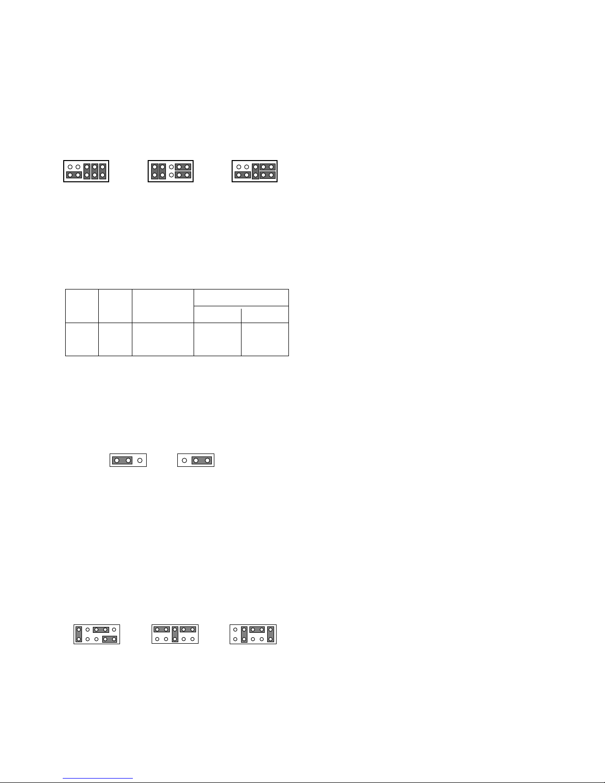
66
• Position jumper connectors (CN101, CN151, CN201,
CN251, CN301, CN351, CN401, CN451, CN501,
CN551, CN601, CN651, CN701, CN751, CN801, and
CN851) on the board as shown below. The jumper connector positions designate the stage of cages as
described previously.
Note: If the system is smaller than 1 024 inputs
times 128 outputs, the settings (factory default
settings) may not need to be changed for extensions.
CN101
2
19
10
CN101
2
19
10
CN101
2
19
10
Initial-stage cage Middle-stage cage Final-stage cage
Crosspoint Output Boards
• Set switches (SW702 and SW703) on the WJ-PB85M16
Crosspoint Output Boards to designate the board numbers as shown in the following table.
Slot
No.
Video In/Out
SW Positions
SW703 SW702
17
18
Board
No.
1
2
0
0
0
1
1 - 16
17 - 32
• Position jumper connectors (CN217, CN218, CN219,
CN220, CN221, CN222, CN223, CN224, CN225,
CN226, CN227, CN228, CN229, CN230, CN231,
CN232) on the board to assign outputs as shown
below.
13
Output 1-16
13
Output 17-32
• Position jumper connectors (CN201, CN202, CN203,
CN204, CN205, CN206, CN207, CN208, CN209,
CN210, CN211, CN212, CN213, CN214, CN215,
CN216) on the board as shown below. The jumper connector positions designate the stage of cages as
described previously.
Note: If the system is smaller than 1 024 inputs
times 128 outputs, the settings (factory default
settings) may not need to be changed for extensions.
CN201
2
10
1
9
Initial-stage cage
CN201
2
10
1
9
Middle-stage cage
CN201
2
10
1
9
Final-stage cage
For other DIP switch settings, refer to the Board
Setting of the individual board.
Page 65
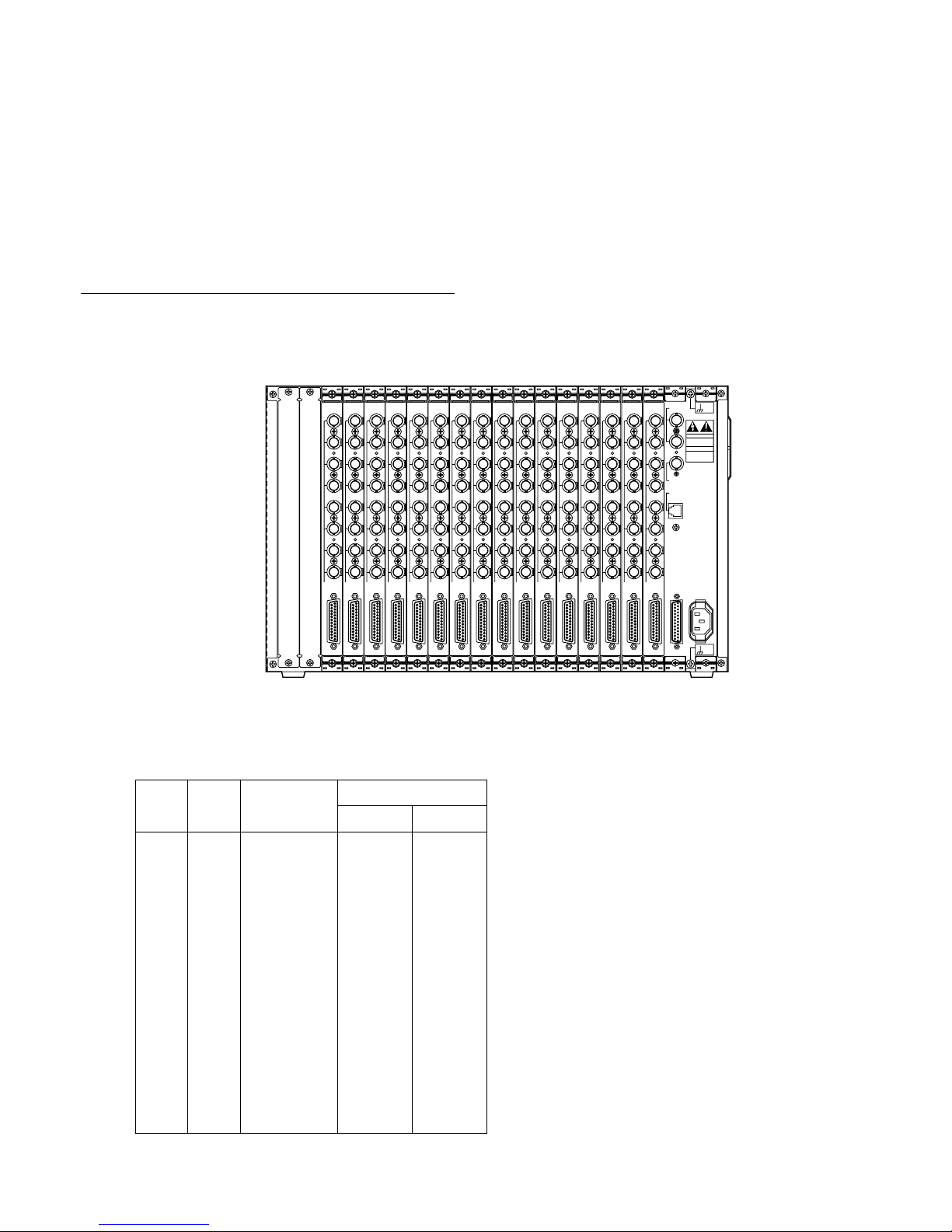
67
■ On-Screen Display (OSD) Bay
The function of the On-Screen Display Bay is to display the camera title, clock and system status on the active monitors. The
basic card cage (MXOSD) has a maximum of 128 video inputs and outputs. Multiple MXOSDs can be combined to support up
to 1 024 inputs and outputs.
The MXOSD is composed of the following individual functional modules:
• Card cage WJ-SX850
• 8ch On-Screen Display Board WJ-PB85T08
● Application
An MXOSD fully equipped for 128 inputs and outputs contains the following:
Description Model No. Qty.
Card Cage WJ-SX850 1
8ch On-Screen Display Board WJ-PB85T08 16
Install the On-Screen Display Boards into the slots (1 to 16) in the Card cage as shown below.
DO NOT OPEN
RISK OF ELECTRIC SHOCK.
SIGNAL
GND
SIGNAL
GND
RS-232C
CAUTION
ATTENTION
NE PAS OUVRIR
RISQUE DE CHOCS
ELECTROUES
VS / VD
IN
OUT
VD OUT
ETHERNET
AC IN
1
2
3
4
5
6
7
8
MONITOR OUT
VIDEO IN
OSD
1
2
3
4
5
6
7
8
MONITOR OUT
VIDEO IN
OSD
1
2
3
4
5
6
7
8
MONITOR OUT
VIDEO IN
OSD
1
2
3
4
5
6
7
8
MONITOR OUT
VIDEO IN
OSD
1
2
3
4
5
6
7
8
MONITOR OUT
VIDEO IN
OSD
1
2
3
4
5
6
7
8
MONITOR OUT
VIDEO IN
OSD
1
2
3
4
5
6
7
8
MONITOR OUT
VIDEO IN
OSD
1
2
3
4
5
6
7
8
MONITOR OUT
VIDEO IN
OSD
1
2
3
4
5
6
7
8
MONITOR OUT
VIDEO IN
OSD
1
2
3
4
5
6
7
8
MONITOR OUT
VIDEO IN
OSD
1
2
3
4
5
6
7
8
MONITOR OUT
VIDEO IN
OSD
1
2
3
4
5
6
7
8
MONITOR OUT
VIDEO IN
OSD
1
2
3
4
5
6
7
8
MONITOR OUT
VIDEO IN
OSD
1
2
3
4
5
6
7
8
MONITOR OUT
VIDEO IN
OSD
1
2
3
4
5
6
7
8
MONITOR OUT
VIDEO IN
OSD
1
2
3
4
5
6
7
8
MONITOR OUT
VIDEO IN
OSD
[Board Setting]
• Set switches (SW1 and SW2) on the WJ-PB85T08 On-Screen Display Boards to designate the board numbers as shown in
the following table.
Slot
No.
Monitor
Output
SW Positions
SW2 SW1
1
2
3
4
5
6
7
8
9
10
11
12
13
14
15
16
Board
No.
1
2
3
4
5
6
7
8
9
10
11
12
13
14
15
16
0
0
0
0
0
0
0
0
0
0
0
0
0
0
0
0
0
1
2
3
4
5
6
7
8
9
A
B
C
D
E
F
1 - 8
9 - 16
17 - 24
25 - 32
33 - 40
41 - 48
49 - 56
57 - 64
65 - 72
73 - 80
81 - 88
89 - 96
97 - 104
105 - 112
113 - 120
121 - 128
For other DIP switch settings, refer to the Board
Setting of the individual board.
Page 66
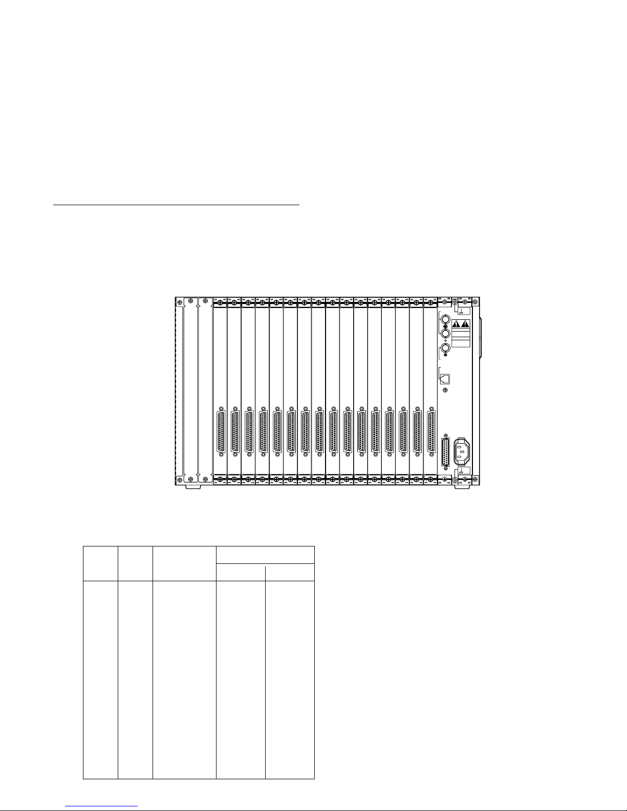
68
■ Matrix Alarm Interface
The Matrix Alarm Interface is a scalable distributed digital input/output unit. Alarm input/output ports, each with a specific
functions, control the alarm processes. The basic input/output element (MXALM) has a maximum capacity of 512 digital inputs
or 512 digital outputs. Capacity can be expanded up to 1 024 inputs/outputs by combining two units.
The MXALM is composed of the following individual functional modules:
• Card cage WJ-SX850
• 32ch Alarm Input Board WJ-PB85A32
• 32ch Alarm Output Board WJ-PB85L32
● Application
An MXALM fully equipped for 512 inputs or outputs contains the following:
Description Model No. Qty.
Card Cage WJ-SX850 1
32ch Alarm Input Board WJ-PB85A32 16
or
32ch Alarm Output Board WJ-PB85L32 16
Install the Alarm Input Boards (or Alarm Output Boards) into the slots (1 to 16) in the Card Cage as shown below.
DO NOT OPEN
RISK OF ELECTRIC SHOCK.
SIGNAL
GND
SIGNAL
GND
RS-232C
CAUTION
ATTENTION
NE PAS OUVRIR
RISQUE DE CHOCS
ELECTROUES
VS / VD
IN
OUT
VD OUT
ETHERNET
AC IN
1-32
ALARM
IN
1-32
ALARM
IN
1-32
ALARM
IN
1-32
ALARM
IN
1-32
ALARM
IN
1-32
ALARM
IN
1-32
ALARM
IN
1-32
ALARM
IN
1-32
ALARM
IN
1-32
ALARM
IN
1-32
ALARM
IN
1-32
ALARM
IN
1-32
ALARM
IN
1-32
ALARM
IN
1-32
ALARM
IN
1-32
ALARM
IN
[Board setting]
• Set switches (SW1 and SW2) on the WJ-PB85A32 Alarm Input Boards or the WJ-PB85L32 Alarm Output Boards to designate the board numbers as shown in the following table.
Slot
No.
Alarm In/Out
SW Positions
SW2 SW1
1
2
3
4
5
6
7
8
9
10
11
12
13
14
15
16
Board
No.
1
2
3
4
5
6
7
8
9
10
11
12
13
14
15
16
0
0
0
0
0
0
0
0
0
0
0
0
0
0
0
0
0
1
2
3
4
5
6
7
8
9
A
B
C
D
E
F
1 - 32
33 - 64
65 - 96
97 - 128
129 - 160
161 - 192
193 - 224
225 - 256
257 - 288
289 - 320
321 - 352
353 - 384
385 - 416
417 - 448
449 - 480
481 - 512
For other DIP switch settings, refer to the Board
Setting of the individual board.
Page 67
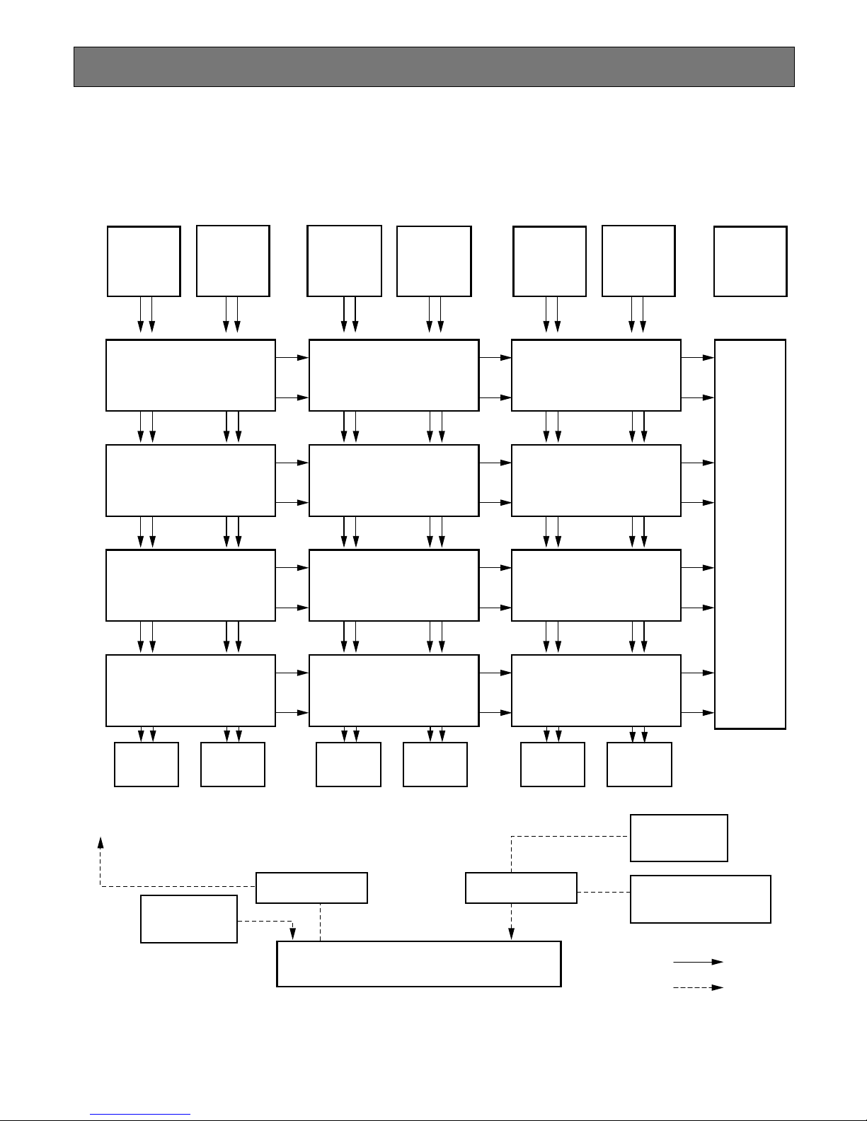
70
SYSTEM CONNECTIONS
The connections described below should be made by qualified service personnel or system installers in accordance
with all local codes.
The diagram below shows how the system components are connected within the system.with all local codes.
MXOSD
MXCONT
6
256 IN
256 OUT
MXSW 13
32
OUT
32
IN
C768
C641 C640 C513
M CPU
1
32
256 IN
256 OUT
MXSW 23
32
OUT
32
IN
33
64
256 IN
256 OUT
MXSW 33
32
OUT
32
IN
65
96
256 IN
256 OUT
MXSW 43
32
OUT
32
IN
97
128
256 IN
256 OUT
MXSW 12
32
OUT
32
IN
C512
C385 C384 C257
256 IN
256 OUT
MXSW 22
32
OUT
32
IN
256 IN
256 OUT
MXSW 32
32
OUT
32
IN
256 IN
256 OUT
MXSW 42
32
OUT
32
IN
256 IN
256 OUT
MXSW 11
32
OUT
32
IN
C256
C129 C128 C1
M1
M32
M33
M64
M65
M96
M97
M128
256 IN
256 OUT
MXSW 21
32
OUT
32
IN
256 IN
256 OUT
MXSW 31
32
OUT
32
IN
256 IN
256 OUT
MXSW 41
32
OUT
32
IN
128 OUT
MXCONT
5
128 OUT
MXCONT
4
128 OUT
MXCONT
3
128 OUT
MXCONT
2
128 OUT
MXCONT
1
128 OUT
MXALM
Ethernet Hub
Controllers
WV-CU350
Ethernet Hub
Controllers
WV-CU850
Personal Computer
AD-GUI
To Cages
Video
Data
Loop
Through
Loop
Through
Loop
Through
Loop
Through
Loop
Through
Loop
Through
Page 68
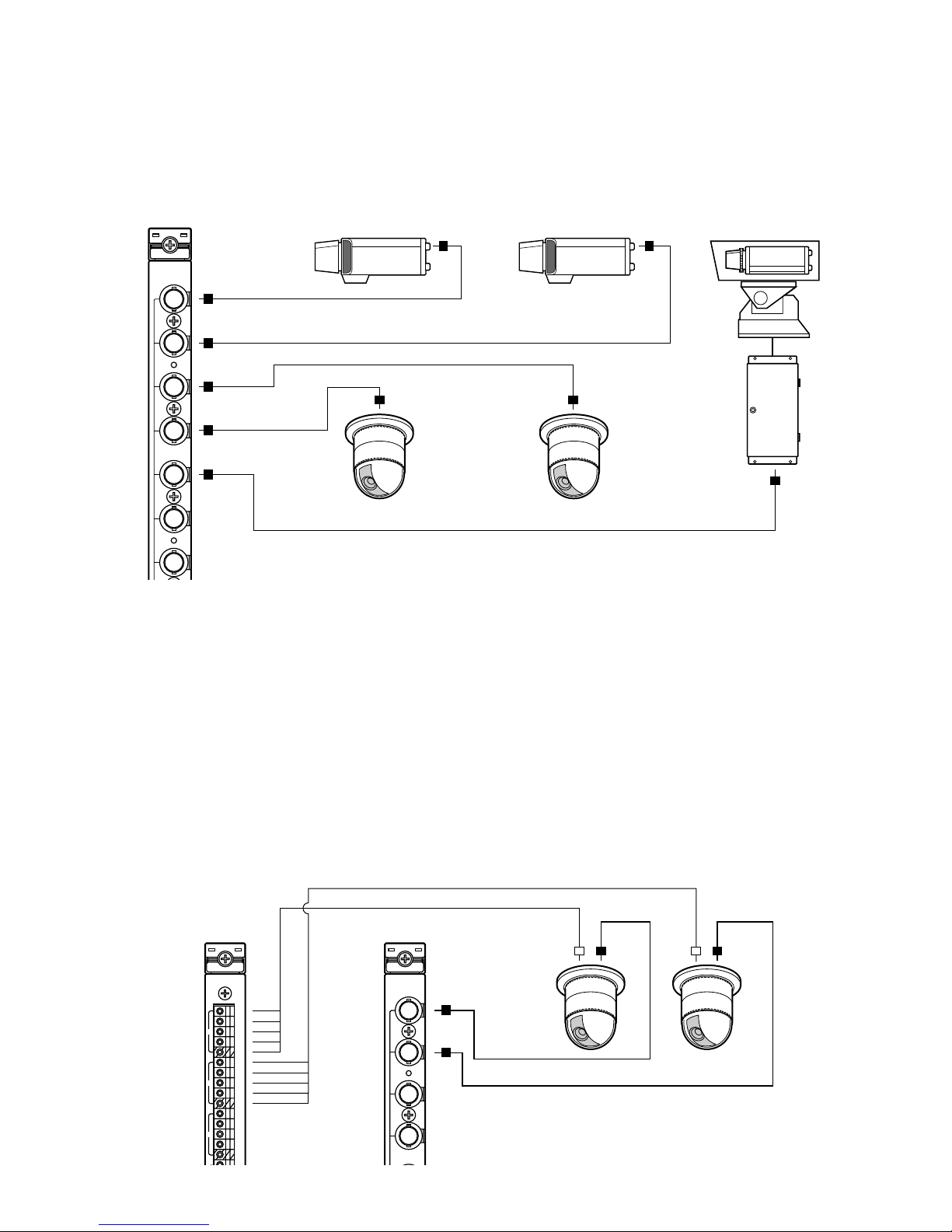
71
■ Connection with the Camera Sites
● Data Multiplexed Cameras
Connect data multiplexed cameras (or camera site equipment) to the Camera Input (CAMERA IN, 1 - 8) connectors on the
Camera Input Board in the Camera Control Cage (MXCONT).
Caution: Make sure that the cable length between the camera site and the MXCONT is less than 900 m (3 000 ft) when using
RG-59/U, BELDEN 9259 or equivalent cable.
1
2
3
4
5
6
7
CAMERA
Receiver
● RS-485 Cameras
For cameras equipped with RS-485 communication feature, this will lower signal loss and extend the distance as video
signal and data are transmitted separately.
Connect the video output of the camera (or camera site equipment) to the Through I/O connector on the Loop-Through
Board in the Camera Control Cage (MXCONT).
Connect RS-485 cable between camera and Data connector on the RS485 Data Board of the Camera Control Cage
(MXCONT).
Note: If you use cables assembled from locally procured materials, it is important that only high quality, data grade cable,
suitable for RS-485 interface “shielded 4-wire twisted pair cable, BELDEN 9406 or equivalent, is used.
Low grade cable will result in unstable operation of the system.
RS485
A
T
B
A
R
B
G
A
T
B
A
R
B
G
A
T
B
A
R
B
G
1
2
3
1
2
3
4
THRU
Page 69
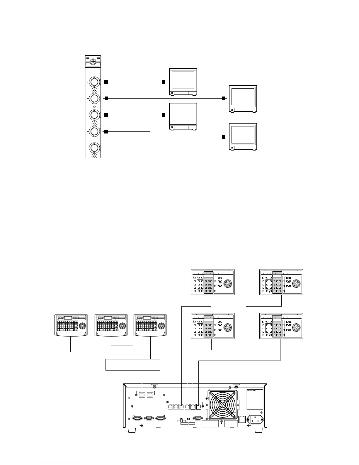
72
■ Connection with the Monitors
Connect the monitors to the Monitor Output (MONITOR OUT, 1 - 8) connector on the On-Screen Display Board in the OnScreen Display Cage (MXOSD).
1
2
3
4
5
OSD
■ Connection with the System Controllers
There are two types of system controllers, the RS-485 type corresponding to an RS-485 and the Ethernet type to an Ethernet
interface.
● WV-CU850 Controller (Ethernet)
Connect the controllers to the Ethernet Port (SYSTEM CONTROLLER) on the rear of the Main CPU via an Ethernet Hub
(equipped for 10Base-T).
● WV-CU350 Controller (RS-485)
Connect the controllers to the SYSTEM CONTROLLER (RS-485) Ports on the rear of the Main CPU.
ALARM
ACK
RESET
ALL
RESET
ARM
GROUP
PRESET
PREV
S-CTL IDOPE ID
NEXT
GROUP
SEQ
PAUSE STOP
TOUR
SEQ
REV
RUN
FWD
RUN
OSD
F.1 F.2 F.3
CMENU
OFF
F.4
CMENU
ON
F.5 F.6
CLOSE
IRIS
WIPER
OPEN
NEAR FAR
UP
BUSY
ACK
LOCK
CAMERA
INFORMATION
MONITOR
ALARM LINK OPERATE
DOWN
R
L
WIDE TELE
AUTO FOCUS
ZOOM
MONITOR
LOCK
LOGOUT
AUX1 OFF AUX1 ON
CALL
PRESET
PGM
PRESET
CAM
POSI
DIGITAL
OUT
CAMERA
(ENTER)
CAM ID GEN
(
ALARM
)
0
87
DEF OFF
AUTO PAN
DEF ON
MSTATUS
ALL
5964
231
SHIFT
CLEAR
(
ESC
)
System Controller WU–CU
850
BUSY
AREA
AUX2 OFF AUX2 ON
DEFAULT
FOCUS
ALARM
ACK
RESET
ALL
RESET
ARM
GROUP
PRESET
PREV
S-CTL IDOPE ID
NEXT
GROUP
SEQ
PAUSE STOP
TOUR
SEQ
REV
RUN
FWD
RUN
OSD
F.1 F.2 F.3
CMENU
OFF
F.4
CMENU
ON
F.5 F.6
CLOSE
IRIS
WIPER
OPEN
NEAR FAR
UP
BUSY
ACK
LOCK
CAMERA
INFORMATION
MONITOR
ALARM LINK OPERATE
DOWN
R
L
WIDE TELE
AUTO FOCUS
ZOOM
MONITOR
LOCK
LOGOUT
AUX1 OFF AUX1 ON
CALL
PRESET
PGM
PRESET
CAM
POSI
DIGITAL
OUT
CAMERA
(ENTER)
CAM ID GEN
(
ALARM
)
0
87
DEF OFF
AUTO PAN
DEF ON
MSTATUS
ALL
5964
231
SHIFT
CLEAR
(
ESC
)
System Controller WU–CU
850
BUSY
AREA
AUX2 OFF AUX2 ON
DEFAULT
FOCUS
PARALLEL
SATELLITE
MODE
REDUNDANT
CPU
ETHERNET
1
CAMERA
CROSS POINT
OSD
GYGTEM
CONTROLLER
DATA 6 DATA 5 DATA 4 DATA 3 DATA 2 DATA 1
PERIFERAL INTERFACE (RS–232C
)
(
RS–485
)
SYSYTEM
CONTROLLER
23
SATELLITE
STANDALONE
YESNO
AC IN
Central Processing Unit
125V 3.0A
SIGNAL
GND
OPERATE LINK ALARM MONITOR CAMERA BUSY PROHIBITED
PROGRAM
PRESET
IRIS
System ControllerWV-CU
350
For Matrix Switcher (System 850
)
OPENCLOSE
AUTO IRIS
CALL
PRESET
AUX1 OFF
CAM ID
AUX1 ON
RESETACK
NEXTPREV
S-CTL ID
STOPPAUSE
CAM MENU ONCAM MENU OFF
TOUR
SEQ
GROUP
SEQ
MONITOR
LOCK
OSD
ALARM
DISARM
ALL RESET
OPE ID
GROUP
PRESET
LOG OUT
F1
F2
GEN
WIPER
AUX2 OFF
MON STATUS
AUX2 ON
ALL
SHIFT
CLEAR
(
ESC
)
DEF OFF DEF ON
CAMERA
(
ENTER
)
AUTO
PAN
FOCUS
FARNEAR
AUTO FOCUS
ZOOM
DOWN
UP
RL
TELEWIDE
OPERATE LINK ALARM MONITOR CAMERA BUSY PROHIBITED
PROGRAM
PRESET
IRIS
System ControllerWV-CU
350
For Matrix Switcher (System 850
)
OPENCLOSE
AUTO IRIS
CALL
PRESET
AUX1 OFF
CAM ID
AUX1 ON
RESETACK
NEXTPREV
S-CTL ID
STOPPAUSE
CAM MENU ONCAM MENU OFF
TOUR
SEQ
GROUP
SEQ
MONITOR
LOCK
OSD
ALARM
DISARM
ALL RESET
OPE ID
GROUP
PRESET
LOG OUT
F1
F2
GEN
WIPER
AUX2 OFF
MON STATUS
AUX2 ON
ALL
SHIFT
CLEAR
(
ESC
)
DEF OFF DEF ON
CAMERA
(
ENTER
)
AUTO
PAN
FOCUS
FARNEAR
AUTO FOCUS
ZOOM
DOWN
UP
RL
TELEWIDE
OPERATE LINK ALARM MONITOR CAMERA BUSY PROHIBITED
PROGRAM
PRESET
IRIS
System ControllerWV-CU
350
For Matrix Switcher (System 850
)
OPENCLOSE
AUTO IRIS
CALL
PRESET
AUX1 OFF
CAM ID
AUX1 ON
RESETACK
NEXTPREV
S-CTL ID
STOPPAUSE
CAM MENU ONCAM MENU OFF
TOUR
SEQ
GROUP
SEQ
MONITOR
LOCK
OSD
ALARM
DISARM
ALL RESET
OPE ID
GROUP
PRESET
LOG OUT
F1
F2
GEN
WIPER
AUX2 OFF
MON STATUS
AUX2 ON
ALL
SHIFT
CLEAR
(
ESC
)
DEF OFF DEF ON
CAMERA
(
ENTER
)
AUTO
PAN
FOCUS
FARNEAR
AUTO FOCUS
ZOOM
DOWN
UP
RL
TELEWIDE
OPERATE LINK ALARM MONITOR CAMERA BUSY PROHIBITED
PROGRAM
PRESET
IRIS
System ControllerWV-CU
350
For Matrix Switcher (System 850
)
OPENCLOSE
AUTO IRIS
CALL
PRESET
AUX1 OFF
CAM ID
AUX1 ON
RESETACK
NEXTPREV
S-CTL ID
STOPPAUSE
CAM MENU ONCAM MENU OFF
TOUR
SEQ
GROUP
SEQ
MONITOR
LOCK
OSD
ALARM
DISARM
ALL RESET
OPE ID
GROUP
PRESET
LOG OUT
F1
F2
GEN
WIPER
AUX2 OFF
MON STATUS
AUX2 ON
ALL
SHIFT
CLEAR
(
ESC
)
DEF OFF DEF ON
CAMERA
(
ENTER
)
AUTO
PAN
FOCUS
FARNEAR
AUTO FOCUS
ZOOM
DOWN
UP
RL
TELEWIDE
Ethernet Hub
ALARM
ACK
RESET
ALL
RESET
ARM
GROUP
PRESET
PREV
S-CTL IDOPE ID
NEXT
GROUP
SEQ
PAUSE STOP
TOUR
SEQ
REV
RUN
FWD
RUN
OSD
F.1 F.2 F.3
CMENU
OFF
F.4
CMENU
ON
F.5 F.6
CLOSE
IRIS
WIPER
OPEN
NEAR FAR
UP
BUSY
ACK
LOCK
CAMERA
INFORMATION
MONITOR
ALARM LINK OPERATE
DOWN
R
L
WIDE TELE
AUTO FOCUS
ZOOM
MONITOR
LOCK
LOGOUT
AUX1 OFF AUX1 ON
CALL
PRESET
PGM
PRESET
CAM
POSI
DIGITAL
OUT
CAMERA
(ENTER)
CAM ID GEN
(
ALARM
)
0
87
DEF OFF
AUTO PAN
DEF ON
MSTATUS
ALL
5964
231
SHIFT
CLEAR
(
ESC
)
System Controller WU–CU
850
BUSY
AREA
AUX2 OFF AUX2 ON
DEFAULT
FOCUS
Page 70
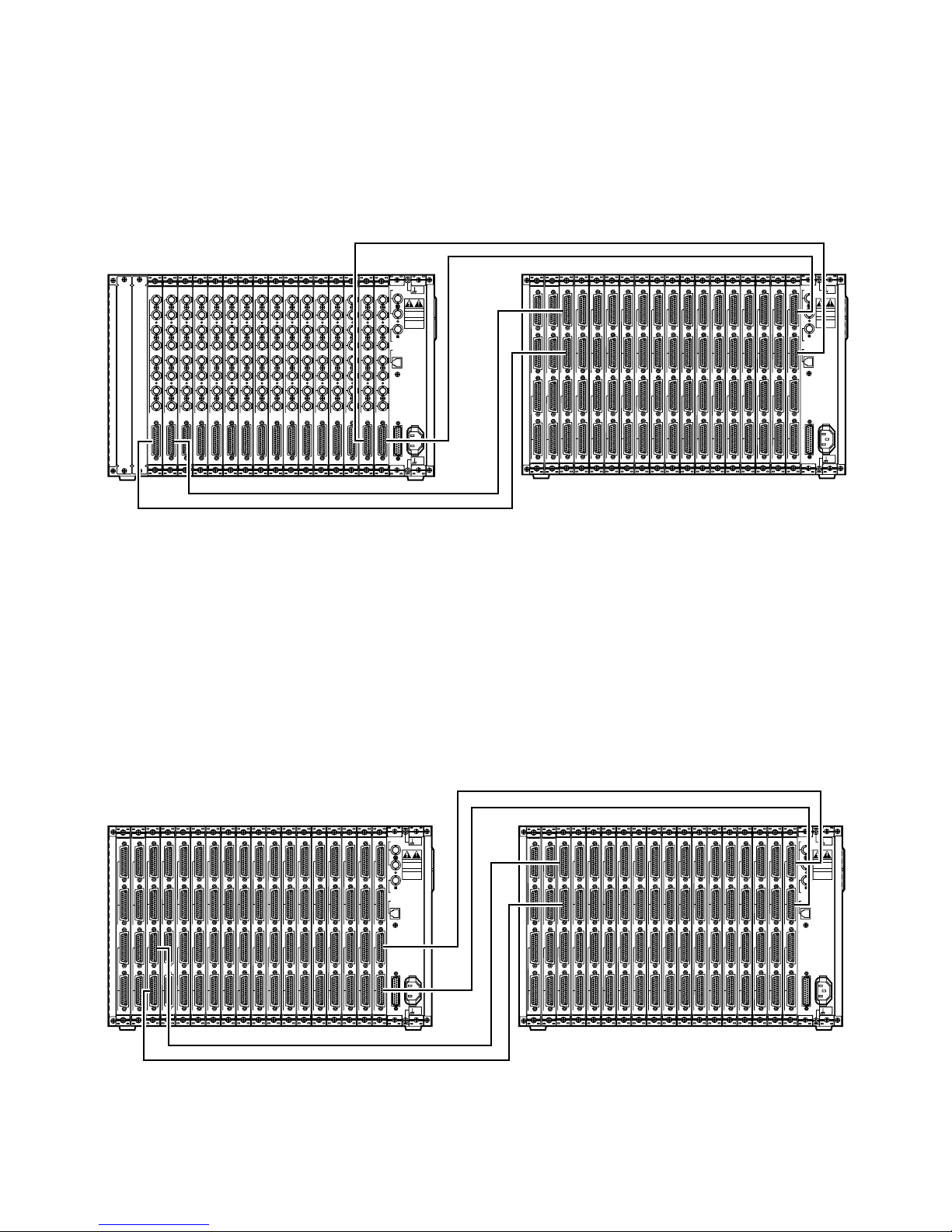
73
■ Connections between the Cages
Connect the extension boards in the cages with the WJ-CA85L Series Extension Cables.
● Connections between the MXCONT and MXSW
For example, connect the VIDEO OUT port on the Camera Input Board (Board 1) in the MXCONT1 and the VIDEO IN 1
port on the Crosspoint Input Board (Board 1) in the MXSW11 with the Extension Cable.
Similarly, connect other extension boards as shown in the figure below.
1
2
3
4
5
6
7
8
CAMERA IN
VIDEO OUT
CAMERA
1
2
3
4
5
6
7
8
CAMERA IN
VIDEO OUT
CAMERA
1
2
3
4
5
6
7
8
CAMERA IN
VIDEO OUT
CAMERA
1
2
3
4
5
6
7
8
CAMERA IN
VIDEO OUT
CAMERA
1
2
3
4
5
6
7
8
CAMERA IN
VIDEO OUT
CAMERA
1
2
3
4
5
6
7
8
CAMERA IN
VIDEO OUT
CAMERA
1
2
3
4
5
6
7
8
CAMERA IN
VIDEO OUT
CAMERA
1
2
3
4
5
6
7
8
CAMERA IN
VIDEO OUT
CAMERA
1
2
3
4
5
6
7
8
CAMERA IN
VIDEO OUT
CAMERA
1
2
3
4
5
6
7
8
CAMERA IN
VIDEO OUT
CAMERA
1
2
3
4
5
6
7
8
CAMERA IN
VIDEO OUT
CAMERA
1
2
3
4
5
6
7
8
CAMERA IN
VIDEO OUT
CAMERA
1
2
3
4
5
6
7
8
CAMERA IN
VIDEO OUT
CAMERA
1
2
3
4
5
6
7
8
CAMERA IN
VIDEO OUT
CAMERA
1
2
3
4
5
6
7
8
CAMERA IN
VIDEO OUT
CAMERA
1
2
3
4
5
6
7
8
CAMERA IN
VIDEO OUT
CAMERA
DO NOT OPEN
RISK OF ELECTRIC SHOCK.
SIGNAL
GND
SIGNAL
GND
RS-232C
CAUTION
ATTENTION
NE PAS OUVRIR
RISQUE DE CHOCS
ELECTROUES
VS / VD
IN
OUT
VD OUT
ETHERNET
AC IN
1
2
VIDEO IN
1
2
VIDEO OUT
INPUT
1
2
VIDEO IN
1
2
VIDEO OUT
INPUT
1
2
VIDEO IN
1
2
VIDEO OUT
INPUT
1
2
VIDEO IN
1
2
VIDEO OUT
INPUT
1
2
VIDEO IN
1
2
VIDEO OUT
INPUT
1
2
VIDEO IN
1
2
VIDEO OUT
INPUT
1
2
VIDEO IN
1
2
VIDEO OUT
INPUT
1
2
VIDEO IN
1
2
VIDEO OUT
INPUT
1
2
VIDEO IN
1
2
VIDEO OUT
INPUT
1
2
VIDEO IN
1
2
VIDEO OUT
INPUT
1
2
VIDEO IN
1
2
VIDEO OUT
INPUT
1
2
VIDEO IN
1
2
VIDEO OUT
INPUT
1
2
VIDEO IN
1
2
VIDEO OUT
INPUT
1
2
VIDEO IN
1
2
VIDEO OUT
INPUT
1
2
VIDEO IN
1
2
VIDEO OUT
INPUT
1
2
VIDEO IN
1
2
VIDEO OUT
INPUT
1
2
VIDEO IN
1
2
VIDEO OUT
OUTPUT
1
2
VIDEO IN
1
2
VIDEO OUT
OUTPUT
DO NOT OPEN
RISK OF ELECTRIC SHOCK.
SIGNAL
GND
SIGNAL
GND
RS-232C
CAUTION
ATTENTION
NE PAS OUVRIR
RISQUE DE CHOCS
ELECTROUES
VS / VD
IN
OUT
VD OUT
ETHERNET
AC IN
MXCONT MXSW
● Connections between the MXSWs
1. For example, connect the VIDEO OUT 1 port on the Crosspoint Input Board (Board 1) in the MXSW11 and the VIDEO
IN 1 port on the Crosspoint Input Board (Board 1) in the MXSW21 with the Extension Cable.
Similarly, connect other extension boards as shown in the figure below.
1
2
VIDEO IN
1
2
VIDEO OUT
INPUT
1
2
VIDEO IN
1
2
VIDEO OUT
INPUT
1
2
VIDEO IN
1
2
VIDEO OUT
INPUT
1
2
VIDEO IN
1
2
VIDEO OUT
INPUT
1
2
VIDEO IN
1
2
VIDEO OUT
INPUT
1
2
VIDEO IN
1
2
VIDEO OUT
INPUT
1
2
VIDEO IN
1
2
VIDEO OUT
INPUT
1
2
VIDEO IN
1
2
VIDEO OUT
INPUT
1
2
VIDEO IN
1
2
VIDEO OUT
INPUT
1
2
VIDEO IN
1
2
VIDEO OUT
INPUT
1
2
VIDEO IN
1
2
VIDEO OUT
INPUT
1
2
VIDEO IN
1
2
VIDEO OUT
INPUT
1
2
VIDEO IN
1
2
VIDEO OUT
INPUT
1
2
VIDEO IN
1
2
VIDEO OUT
INPUT
1
2
VIDEO IN
1
2
VIDEO OUT
INPUT
1
2
VIDEO IN
1
2
VIDEO OUT
INPUT
1
2
VIDEO IN
1
2
VIDEO OUT
OUTPUT
1
2
VIDEO IN
1
2
VIDEO OUT
OUTPUT
DO NOT OPEN
RISK OF ELECTRIC SHOCK.
SIGNAL
GND
SIGNAL
GND
RS-232C
CAUTION
ATTENTION
NE PAS OUVRIR
RISQUE DE CHOCS
ELECTROUES
VS / VD
IN
OUT
VD OUT
ETHERNET
AC IN
1
2
VIDEO IN
1
2
VIDEO OUT
INPUT
1
2
VIDEO IN
1
2
VIDEO OUT
INPUT
1
2
VIDEO IN
1
2
VIDEO OUT
INPUT
1
2
VIDEO IN
1
2
VIDEO OUT
INPUT
1
2
VIDEO IN
1
2
VIDEO OUT
INPUT
1
2
VIDEO IN
1
2
VIDEO OUT
INPUT
1
2
VIDEO IN
1
2
VIDEO OUT
INPUT
1
2
VIDEO IN
1
2
VIDEO OUT
INPUT
1
2
VIDEO IN
1
2
VIDEO OUT
INPUT
1
2
VIDEO IN
1
2
VIDEO OUT
INPUT
1
2
VIDEO IN
1
2
VIDEO OUT
INPUT
1
2
VIDEO IN
1
2
VIDEO OUT
INPUT
1
2
VIDEO IN
1
2
VIDEO OUT
INPUT
1
2
VIDEO IN
1
2
VIDEO OUT
INPUT
1
2
VIDEO IN
1
2
VIDEO OUT
INPUT
1
2
VIDEO IN
1
2
VIDEO OUT
INPUT
1
2
VIDEO IN
1
2
VIDEO OUT
OUTPUT
1
2
VIDEO IN
1
2
VIDEO OUT
OUTPUT
DO NOT OPEN
RISK OF ELECTRIC SHOCK.
SIGNAL
GND
SIGNAL
GND
RS-232C
CAUTION
ATTENTION
NE PAS OUVRIR
RISQUE DE CHOCS
ELECTROUES
VS / VD
IN
OUT
VD OUT
ETHERNET
AC IN
MXSWMXSW
MXSW11 → MXSW21→ MXSW31 → MXSW41
MXSW12 → MXSW22→ MXSW32 → MXSW42
MXSW13 → MXSW23→ MXSW33 → MXSW43
Page 71
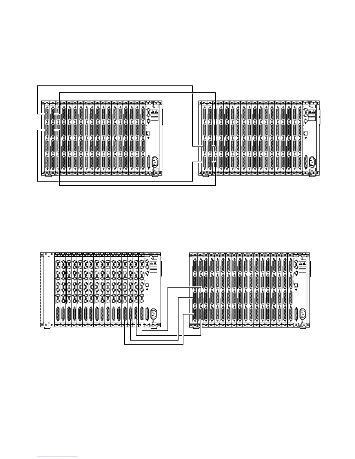
74
2. Connect the VIDEO OUT 1 port on the Crosspoint Output Board (Board 1) in the MXSW13 and the VIDEO IN 1 port on
the Crosspoint Output Board (Board 1) in the MXSW12 with the Extension Cable.
Similarly, connect other extension boards as shown in the figure below.
1
2
VIDEO IN
1
2
VIDEO OUT
INPUT
1
2
VIDEO IN
1
2
VIDEO OUT
INPUT
1
2
VIDEO IN
1
2
VIDEO OUT
INPUT
1
2
VIDEO IN
1
2
VIDEO OUT
INPUT
1
2
VIDEO IN
1
2
VIDEO OUT
INPUT
1
2
VIDEO IN
1
2
VIDEO OUT
INPUT
1
2
VIDEO IN
1
2
VIDEO OUT
INPUT
1
2
VIDEO IN
1
2
VIDEO OUT
INPUT
1
2
VIDEO IN
1
2
VIDEO OUT
INPUT
1
2
VIDEO IN
1
2
VIDEO OUT
INPUT
1
2
VIDEO IN
1
2
VIDEO OUT
INPUT
1
2
VIDEO IN
1
2
VIDEO OUT
INPUT
1
2
VIDEO IN
1
2
VIDEO OUT
INPUT
1
2
VIDEO IN
1
2
VIDEO OUT
INPUT
1
2
VIDEO IN
1
2
VIDEO OUT
INPUT
1
2
VIDEO IN
1
2
VIDEO OUT
INPUT
1
2
VIDEO IN
1
2
VIDEO OUT
OUTPUT
1
2
VIDEO IN
1
2
VIDEO OUT
OUTPUT
DO NOT OPEN
RISK OF ELECTRIC SHOCK.
SIGNAL
GND
SIGNAL
GND
RS-232C
CAUTION
ATTENTION
NE PAS OUVRIR
RISQUE DE CHOCS
ELECTROUES
VS / VD
IN
OUT
VD OUT
ETHERNET
AC IN
1
2
VIDEO IN
1
2
VIDEO OUT
INPUT
1
2
VIDEO IN
1
2
VIDEO OUT
INPUT
1
2
VIDEO IN
1
2
VIDEO OUT
INPUT
1
2
VIDEO IN
1
2
VIDEO OUT
INPUT
1
2
VIDEO IN
1
2
VIDEO OUT
INPUT
1
2
VIDEO IN
1
2
VIDEO OUT
INPUT
1
2
VIDEO IN
1
2
VIDEO OUT
INPUT
1
2
VIDEO IN
1
2
VIDEO OUT
INPUT
1
2
VIDEO IN
1
2
VIDEO OUT
INPUT
1
2
VIDEO IN
1
2
VIDEO OUT
INPUT
1
2
VIDEO IN
1
2
VIDEO OUT
INPUT
1
2
VIDEO IN
1
2
VIDEO OUT
INPUT
1
2
VIDEO IN
1
2
VIDEO OUT
INPUT
1
2
VIDEO IN
1
2
VIDEO OUT
INPUT
1
2
VIDEO IN
1
2
VIDEO OUT
INPUT
1
2
VIDEO IN
1
2
VIDEO OUT
INPUT
1
2
VIDEO IN
1
2
VIDEO OUT
OUTPUT
1
2
VIDEO IN
1
2
VIDEO OUT
OUTPUT
DO NOT OPEN
RISK OF ELECTRIC SHOCK.
SIGNAL
GND
SIGNAL
GND
RS-232C
CAUTION
ATTENTION
NE PAS OUVRIR
RISQUE DE CHOCS
ELECTROUES
VS / VD
IN
OUT
VD OUT
ETHERNET
AC IN
MXSW MXSW
● Connections between the MXSW and MXOSD
For example, connect the VIDEO OUT 1 port on the Crosspoint Output Board (Board 1) in the MXSW11 and the VIDEO IN
port on the On-Screen Board (Board 1) in the MXOSD with the Extension Cable.
Similarly, connect other extension boards as shown in the figure below.
1
2
VIDEO IN
1
2
VIDEO OUT
INPUT
1
2
VIDEO IN
1
2
VIDEO OUT
INPUT
1
2
VIDEO IN
1
2
VIDEO OUT
INPUT
1
2
VIDEO IN
1
2
VIDEO OUT
INPUT
1
2
VIDEO IN
1
2
VIDEO OUT
INPUT
1
2
VIDEO IN
1
2
VIDEO OUT
INPUT
1
2
VIDEO IN
1
2
VIDEO OUT
INPUT
1
2
VIDEO IN
1
2
VIDEO OUT
INPUT
1
2
VIDEO IN
1
2
VIDEO OUT
INPUT
1
2
VIDEO IN
1
2
VIDEO OUT
INPUT
1
2
VIDEO IN
1
2
VIDEO OUT
INPUT
1
2
VIDEO IN
1
2
VIDEO OUT
INPUT
1
2
VIDEO IN
1
2
VIDEO OUT
INPUT
1
2
VIDEO IN
1
2
VIDEO OUT
INPUT
1
2
VIDEO IN
1
2
VIDEO OUT
INPUT
1
2
VIDEO IN
1
2
VIDEO OUT
INPUT
1
2
VIDEO IN
1
2
VIDEO OUT
OUTPUT
1
2
VIDEO IN
1
2
VIDEO OUT
OUTPUT
DO NOT OPEN
RISK OF ELECTRIC SHOCK.
SIGNAL
GND
SIGNAL
GND
RS-232C
CAUTION
ATTENTION
NE PAS OUVRIR
RISQUE DE CHOCS
ELECTROUES
VS / VD
IN
OUT
VD OUT
ETHERNET
AC IN
MXOSD MXSW
DO NOT OPEN
RISK OF ELECTRIC SHOCK.
SIGNAL
GND
SIGNAL
GND
RS-232C
CAUTION
ATTENTION
NE PAS OUVRIR
RISQUE DE CHOCS
ELECTROUES
VS / VD
IN
OUT
VD OUT
ETHERNET
AC IN
1
2
3
4
5
6
7
8
MONITOR OUT
VIDEO IN
OSD
1
2
3
4
5
6
7
8
MONITOR OUT
VIDEO IN
OSD
1
2
3
4
5
6
7
8
MONITOR OUT
VIDEO IN
OSD
1
2
3
4
5
6
7
8
MONITOR OUT
VIDEO IN
OSD
1
2
3
4
5
6
7
8
MONITOR OUT
VIDEO IN
OSD
1
2
3
4
5
6
7
8
MONITOR OUT
VIDEO IN
OSD
1
2
3
4
5
6
7
8
MONITOR OUT
VIDEO IN
OSD
1
2
3
4
5
6
7
8
MONITOR OUT
VIDEO IN
OSD
1
2
3
4
5
6
7
8
MONITOR OUT
VIDEO IN
OSD
1
2
3
4
5
6
7
8
MONITOR OUT
VIDEO IN
OSD
1
2
3
4
5
6
7
8
MONITOR OUT
VIDEO IN
OSD
1
2
3
4
5
6
7
8
MONITOR OUT
VIDEO IN
OSD
1
2
3
4
5
6
7
8
MONITOR OUT
VIDEO IN
OSD
1
2
3
4
5
6
7
8
MONITOR OUT
VIDEO IN
OSD
1
2
3
4
5
6
7
8
MONITOR OUT
VIDEO IN
OSD
1
2
3
4
5
6
7
8
MONITOR OUT
VIDEO IN
OSD
MXSW13 → MXSW22→ MXSW31
MXSW23 → MXSW22→ MXSW21
MXSW33 → MXSW32→ MXSW31
MXSW43 → MXSW42→ MXSW41
Page 72
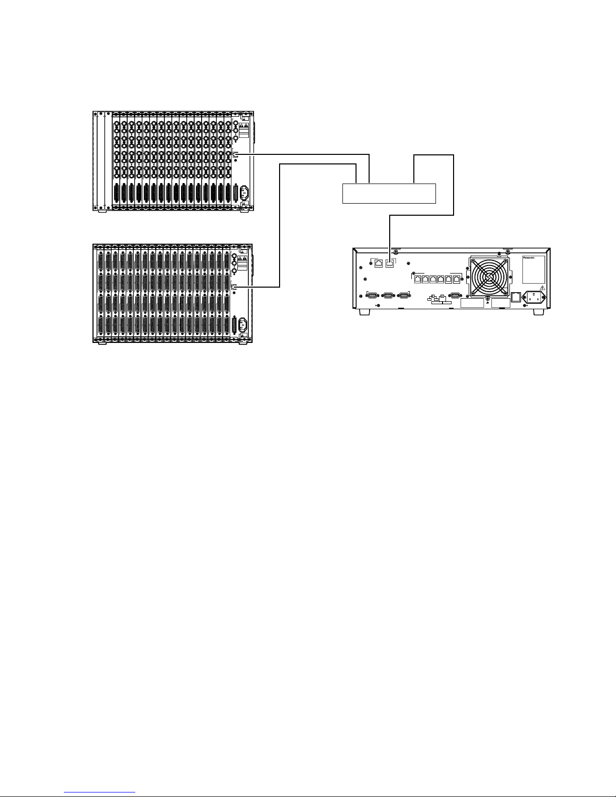
75
● Connection between the PC and CPU
Connect the PC to the Ethernet Port (SYSTEM CONTROLLER) on the rear of the Main CPU via an Ethernet Hub.
● Connections between the Cages and CPU
Connect the ETHERNET port on the Cages to the Ethernet (CAMERA/CROSS POINT/OSD) Port on the CPU via an Ethernet
Hub (equipped for 10Base-T).
1
2
VIDEO IN
1
2
VIDEO OUT
INPUT
1
2
VIDEO IN
1
2
VIDEO OUT
INPUT
1
2
VIDEO IN
1
2
VIDEO OUT
INPUT
1
2
VIDEO IN
1
2
VIDEO OUT
INPUT
1
2
VIDEO IN
1
2
VIDEO OUT
INPUT
1
2
VIDEO IN
1
2
VIDEO OUT
INPUT
1
2
VIDEO IN
1
2
VIDEO OUT
INPUT
1
2
VIDEO IN
1
2
VIDEO OUT
INPUT
1
2
VIDEO IN
1
2
VIDEO OUT
INPUT
1
2
VIDEO IN
1
2
VIDEO OUT
INPUT
1
2
VIDEO IN
1
2
VIDEO OUT
INPUT
1
2
VIDEO IN
1
2
VIDEO OUT
INPUT
1
2
VIDEO IN
1
2
VIDEO OUT
INPUT
1
2
VIDEO IN
1
2
VIDEO OUT
INPUT
1
2
VIDEO IN
1
2
VIDEO OUT
INPUT
1
2
VIDEO IN
1
2
VIDEO OUT
INPUT
1
2
VIDEO IN
1
2
VIDEO OUT
OUTPUT
1
2
VIDEO IN
1
2
VIDEO OUT
OUTPUT
DO NOT OPEN
RISK OF ELECTRIC SHOCK.
SIGNAL
GND
SIGNAL
GND
RS-232C
CAUTION
ATTENTION
NE PAS OUVRIR
RISQUE DE CHOCS
ELECTROUES
VS / VD
IN
OUT
VD OUT
ETHERNET
AC IN
MXSW
MCPU
MXCONT
PARALLEL
SATELLITE
MODE
REDUNDANT
CPU
ETHERNET
1
CAMERA
CROSS POINT
OSD
GYGTEM
CONTROLLER
DATA 6 DATA 5 DATA 4 DATA 3 DATA 2 DATA 1
PERIFERAL INTERFACE (RS–232C
)
(
RS–485
)
SYSYTEM
CONTROLLER
23
SATELLITE
STANDALONE
YESNO
AC IN
Central Processing Unit
125V 3.0A
SIGNAL
GND
Ethernet Hub
1
2
3
4
5
6
7
8
CAMERA IN
VIDEO OUT
CAMERA
1
2
3
4
5
6
7
8
CAMERA IN
VIDEO OUT
CAMERA
1
2
3
4
5
6
7
8
CAMERA IN
VIDEO OUT
CAMERA
1
2
3
4
5
6
7
8
CAMERA IN
VIDEO OUT
CAMERA
1
2
3
4
5
6
7
8
CAMERA IN
VIDEO OUT
CAMERA
1
2
3
4
5
6
7
8
CAMERA IN
VIDEO OUT
CAMERA
1
2
3
4
5
6
7
8
CAMERA IN
VIDEO OUT
CAMERA
1
2
3
4
5
6
7
8
CAMERA IN
VIDEO OUT
CAMERA
1
2
3
4
5
6
7
8
CAMERA IN
VIDEO OUT
CAMERA
1
2
3
4
5
6
7
8
CAMERA IN
VIDEO OUT
CAMERA
1
2
3
4
5
6
7
8
CAMERA IN
VIDEO OUT
CAMERA
1
2
3
4
5
6
7
8
CAMERA IN
VIDEO OUT
CAMERA
1
2
3
4
5
6
7
8
CAMERA IN
VIDEO OUT
CAMERA
1
2
3
4
5
6
7
8
CAMERA IN
VIDEO OUT
CAMERA
1
2
3
4
5
6
7
8
CAMERA IN
VIDEO OUT
CAMERA
1
2
3
4
5
6
7
8
CAMERA IN
VIDEO OUT
CAMERA
DO NOT OPEN
RISK OF ELECTRIC SHOCK.
SIGNAL
GND
SIGNAL
GND
RS-232C
CAUTION
ATTENTION
NE PAS OUVRIR
RISQUE DE CHOCS
ELECTROUES
VS / VD
IN
OUT
VD OUT
ETHERNET
AC IN
● Connection between the MXSW and Loop-Through Cage
Connect as follows if the camera loop-through outputs are required.
For example, connect the VIDEO OUT 1 port on the Crosspoint Input Board (Board 1) in the MXSW 41 and Through I/O
port on the Loop-Through Board in the Loop-Through Cage with the Extension cable.
Similarly, connect other extension boards to the Loop-Through Boards in the Loop-Through Cage.
Page 73
77
OPERATING PROCEDURES
(with WV-CU850)
Page 74
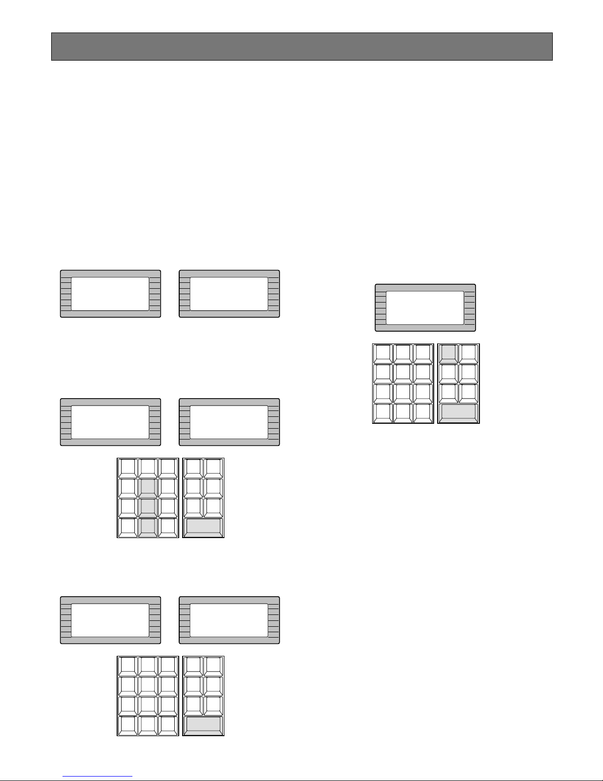
If operator ID and password are correct, “OK” will
appear for 2 seconds on the LCD display.
Note: If an operator ID and password error have
occurred, “NG” will appear for 2 seconds on the
LCD display with a beep sound, then the Log-in
procedure automatically returns to the start.
■ Log-out
This function is used when an operator is leaving the controller, or no longer requires access to the system.
1. Hold down the [LOGOUT] key and then press the
[CAMERA (ENTER)] key to log out.
“NO OPERATOR” is displayed on the LCD display of
the controller.
2. Turn off the Power switch located on the rear of the
controller.
Before starting the following procedures, all system components must be turned on.
The following procedures apply when the WV-CU850
System Controller is connected to the system. Some of
functions are not available when the WV-CU350 System
Controller is connected.
■ Log-in
1. Turn on the power switches of all system components.
2. Press the POWER ON/OFF Switch located on the rear
of the System Controller, to the ON position.
The LINK indicator lights up and the following displays
will appear on the LCD display of the system controller.
3. Select your registered operator ID number (up to 5 digits) by pressing the numeric keys, then press the
[CAMERA (ENTER)] key.
“PASSWORD” will appear on the LCD display of the
controller.
4. Select your registered password (up to 5 digits) by
pressing the numeric keys, then press the [CAMERA
(ENTER)] key.
78
INFORMATION
HELLO!
INFORMATION
ID:
NO OPERATOR
INFORMATION
ID:850
INFORMATION
ID:850
PASSWORD:
–––––
LOGOUT
AUX1 OFF AUX1 ON
CALL
PRESET
PGM
PRESET
CAM
POSI
DIGITAL
OUT
DEF OFF DEF ON
AREA
AUX2 OFF AUX2 ON
CAMERA
(ENTER)
AUTO PAN
CAM ID
VLD S
T&D
ALM S
GEN
SYS S
(
ALARM
)
0
87
MSTA TUS
VLD H
ALL
ALM H
BLK
5964
231
SHIFT
CLEAR
(
ESC
)
EXIT
INFORMATION
ID:850
PASSWORD:
**
INFORMATION
ID:850
PASSWORD:OK
*****
LOGOUT
AUX1 OFF AUX1 ON
CALL
PRESET
PGM
PRESET
CAM
POSI
DIGITAL
OUT
DEF OFF DEF ON
AREA
AUX2 OFF AUX2 ON
CAMERA
(ENTER)
AUTO PAN
CAM ID
VLD S
T&D
ALM S
GEN
SYS S
(
ALARM
)
0
87
MSTA TUS
VLD H
ALL
ALM H
BLK
5964
231
SHIFT
CLEAR
(
ESC
)
EXIT
Log-in and Log-out
INFORMATION
ID:
NO OPERATOR
LOGOUT
AUX1 OFF AUX1 ON
CALL
PRESET
PGM
PRESET
CAM
POSI
DIGITAL
OUT
DEF OFF DEF ON
AREA
AUX2 OFF AUX2 ON
CAMERA
(ENTER)
AUTO PAN
CAM ID
VLD S
T&D
ALM S
GEN
SYS S
(
ALARM
)
0
87
MSTA TUS
VLD H
ALL
ALM H
BLK
5964
231
SHIFT
CLEAR
(
ESC
)
EXIT
Page 75
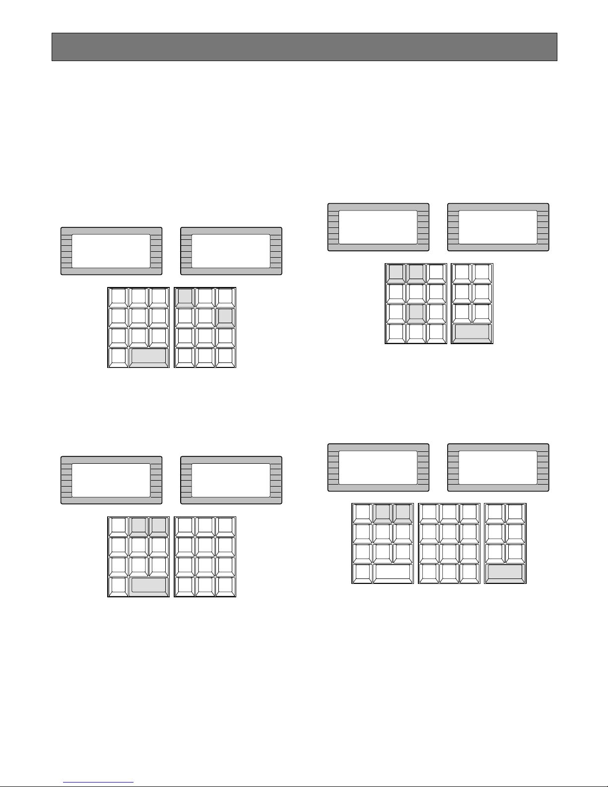
79
After log-in, the following operations are available for controlling the system.
The operation begins with selecting a monitor; then select a
camera to be displayed on the active monitor screen.
■ Monitor Selection
1. Select the desired monitor number by pressing the
numeric keys, then press the [MONITOR] key to execute the selection.
The selected monitor number is now displayed on the
MONITOR display of the controller.
2. Pressing the [NEXT] key while holding down the [MON-
ITOR] key will select the next higher monitor number,
or pressing the [PREV] key while holding down the
[MONITOR] key will select the next lower monitor number.
Note: The MONITOR BUSY indicator lights, if the moni-
tor is selected by a higher priority operator. Control
of the same monitor is denied to an operator with a
lower priority.
■ Camera Selection
1. Select the desired monitor.
Refer to the Monitor Selection.
2. Select the desired camera number by pressing the
numeric keys, then press the [CAMERA (ENTER)] key.
The selected camera picture appears on the active
monitor and the selected camera number is now displayed on the CAMERA display of the controller.
3. Pressing the [NEXT] key while holding down the [CAM-
ERA (ENTER)] key will replace the currently selected
camera with the next higher camera number, or pressing the [PREV] key while holding down the [CAMERA
(ENTER)] key will replace the currently selected camera with the next lower camera number.
Note: The CAMERA BUSY indicator lights, if the cam-
era is selected by a higher priority operator.
Control of the same camera is denied to an operator with a lower priority.
Monitor and Camera Selection
INFORMATION
Entry:16
INFORMATION
Mon16
CAM ID
VLD S
T&D
ALM S
GEN
SYS S
(
ALARM
)
0
87
MSTA TUS
VLD H
ALL
ALM H
BLK
5964
231
SHIFT
CLEAR
(
ESC
)
EXIT
GROUP
PRESET
PREV
S-CTL IDOPE ID
NEXT
GROUP
SEQ
PAUSE STOP
TOUR
SEQ
REV
RUN
FWD
RUN
OSD
VER
MONITOR
LOCK
OSD SERVICE
INFORMATION
Monitor Next
INFORMATION
Monitor Prev
CAM ID
VLD S
T&D
ALM S
GEN
SYS S
(
ALARM
)
0
87
MSTA TUS
VLD H
ALL
ALM H
BLK
5964
231
SHIFT
CLEAR
(
ESC
)
EXIT
GROUP
PRESET
PREV
S-CTL IDOPE ID
NEXT
GROUP
SEQ
PAUSE STOP
TOUR
SEQ
REV
RUN
FWD
RUN
OSD
MONITOR
LOCK
OSD SERVICE
VER
INFORMATION
Entry:128
INFORMATION
Cam 128
LOGOUT
AUX1 OFF AUX1 ON
CALL
PRESET
PGM
PRESET
CAM
POSI
DIGITAL
OUT
DEF OFF DEF ON
AREA
AUX2 OFF AUX2 ON
CAMERA
(ENTER)
AUTO PAN
CAM ID
VLD S
T&D
ALM S
GEN
SYS S
(
ALARM
)
0
87
MSTA TUS
VLD H
ALL
ALM H
BLK
5964
231
SHIFT
CLEAR
(
ESC
)
EXIT
INFORMATION
Camera Next
INFORMATION
Camera Prev
CAM ID
VLD S
T&D
ALM S
GEN
SYS S
(
ALARM
)
0
87
MSTA TUS
VLD H
ALL
ALM H
BLK
5964
231
SHIFT
CLEAR
(
ESC
)
EXIT
LOGOUT
AUX1 OFF AUX1 ON
CALL
PRESET
PGM
PRESET
CAM
POSI
DIGITAL
OUT
DEF OFF DEF ON
AREA
AUX2 OFF AUX2 ON
CAMERA
(ENTER)
AUTO PAN
GROUP
PRESET
PREV
S-CTL IDOPE ID
NEXT
GROUP
SEQ
PAUSE STOP
TOUR
SEQ
REV
RUN
FWD
RUN
OSD
MONITOR
LOCK
OSD SERVICE
VER
Page 76
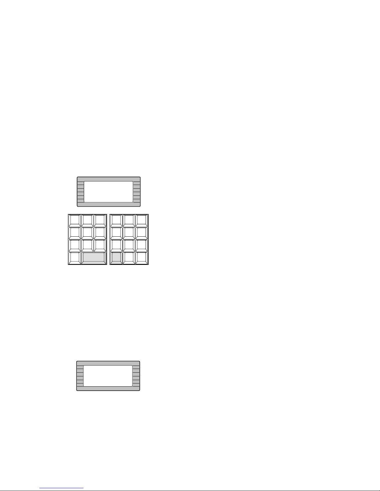
80
■ Priority Lock
This function is used to retain control of a monitor for an
operator, even after that operator has selected another
monitor.
Caution: This function will prevent operators with a lower
priority from gaining control of a monitor.
However, higher or equal priority operators may still
gain control of that monitor.
● Applying Priority Lock
1. Select the desired monitor to apply Priority Lock.
Refer to the Monitor Selection.
2. Pressing the [MONITOR] key while holding down the
[SHIFT] key will toggle the Priority Lock mode on and
off on the active monitor.
If the Priority Lock mode is selected, the monitor number with “L” sign is displayed on the active monitor and
the MONITOR LOCK indicator on the controller is on.
● Releasing Priority Lock
1. Select the desired monitor to release Priority Lock.
Refer to the Monitor Selection.
2. Pressing the [MONITOR] key while holding down the
[SHIFT] key will release the lock mode.
The monitor number is displayed normally on the active
monitor and the MONITOR LOCK indicator on the controller is now off.
INFORMATION
Mon Lock
CAM ID
VLD S
T&D
ALM S
GEN
SYS S
(
ALARM
)
0
87
MSTA TUS
VLD H
ALL
ALM H
BLK
5964
231
SHIFT
CLEAR
(
ESC
)
EXIT
GROUP
PRESET
PREV
S-CTL IDOPE ID
NEXT
GROUP
SEQ
PAUSE STOP
TOUR
SEQ
REV
RUN
FWD
RUN
OSD
VER
MONITOR
LOCK
OSD SERVICE
INFORMATION
Mon Unlock
Page 77
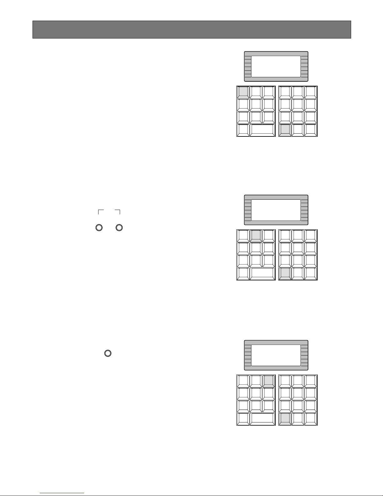
81
Display Setting for Controller
■ Adjustment of LCD Display
The following procedures let you adjust backlight and contrast of the controller’s LCD display.
● Back Light Adjustment
Adjust the back light by turning the LCD BRIGHT control located on the rear of the controller.
Clockwise: increases the back light brightness
Counterclockwise: decreases the back light bright-
ness
● Contrast Adjustment
Adjust the contrast of the characters displayed on the
LCD display by turning the LCD CONTRAST control
located on the rear of the controller.
Clockwise: increases the character contrast
Counterclockwise: decreases the character contrast
■ Adjustment of LED Display
The following procedure lets you adjust the brightness of
the Monitor and Camera LED displays and LED indicators
on the controller.
Adjust the brightness by turning the LED BRIGHT control
located on the rear of the controller.
Clockwise: increases brightness
Counterclockwise: decreases brightness
■ IDs Display Function
This controller has the following functions.
● Operator ID Display
Pressing the [GROUP PRESET] key while holding
down the [SHIFT] key will display the Operator ID number on the LCD display.
● Controller ID Display
Pressing the [PREV] key while holding down the
[SHIFT] key will display the Controller ID number on
the LCD display.
● System Version Display
Pressing the [NEXT] key while holding down the
[SHIFT] key will display the system version number on
the LCD display.
CONTRAST BRIGHT
LCD
BRIGHT
LED
INFORMATION
ID:850
CAM ID
VLD S
T&D
ALM S
GEN
SYS S
(
ALARM
)
0
87
MSTA TUS
VLD H
ALL
ALM H
BLK
5964
231
SHIFT
CLEAR
(
ESC
)
EXIT
GROUP
PRESET
PREV
S-CTL IDOPE ID
NEXT
GROUP
SEQ
PAUSE STOP
TOUR
SEQ
REV
RUN
FWD
RUN
OSD
VER
MONITOR
LOCK
OSD SERVICE
INFORMATION
Sys Ctrl ID:1
CAM ID
VLD S
T&D
ALM S
GEN
SYS S
(
ALARM
)
0
87
MSTA TUS
VLD H
ALL
ALM H
BLK
5964
231
SHIFT
CLEAR
(
ESC
)
EXIT
GROUP
PRESET
PREV
S-CTL IDOPE ID
NEXT
GROUP
SEQ
PAUSE STOP
TOUR
SEQ
REV
RUN
FWD
RUN
OSD
VER
MONITOR
LOCK
OSD SERVICE
INFORMATION
Ver:1.5.0.1
CAM ID
VLD S
T&D
ALM S
GEN
SYS S
(
ALARM
)
0
87
MSTA TUS
VLD H
ALL
ALM H
BLK
5964
231
SHIFT
CLEAR
(
ESC
)
EXIT
GROUP
PRESET
PREV
S-CTL IDOPE ID
NEXT
GROUP
SEQ
PAUSE STOP
TOUR
SEQ
REV
RUN
FWD
RUN
OSD
VER
MONITOR
LOCK
OSD SERVICE
Page 78
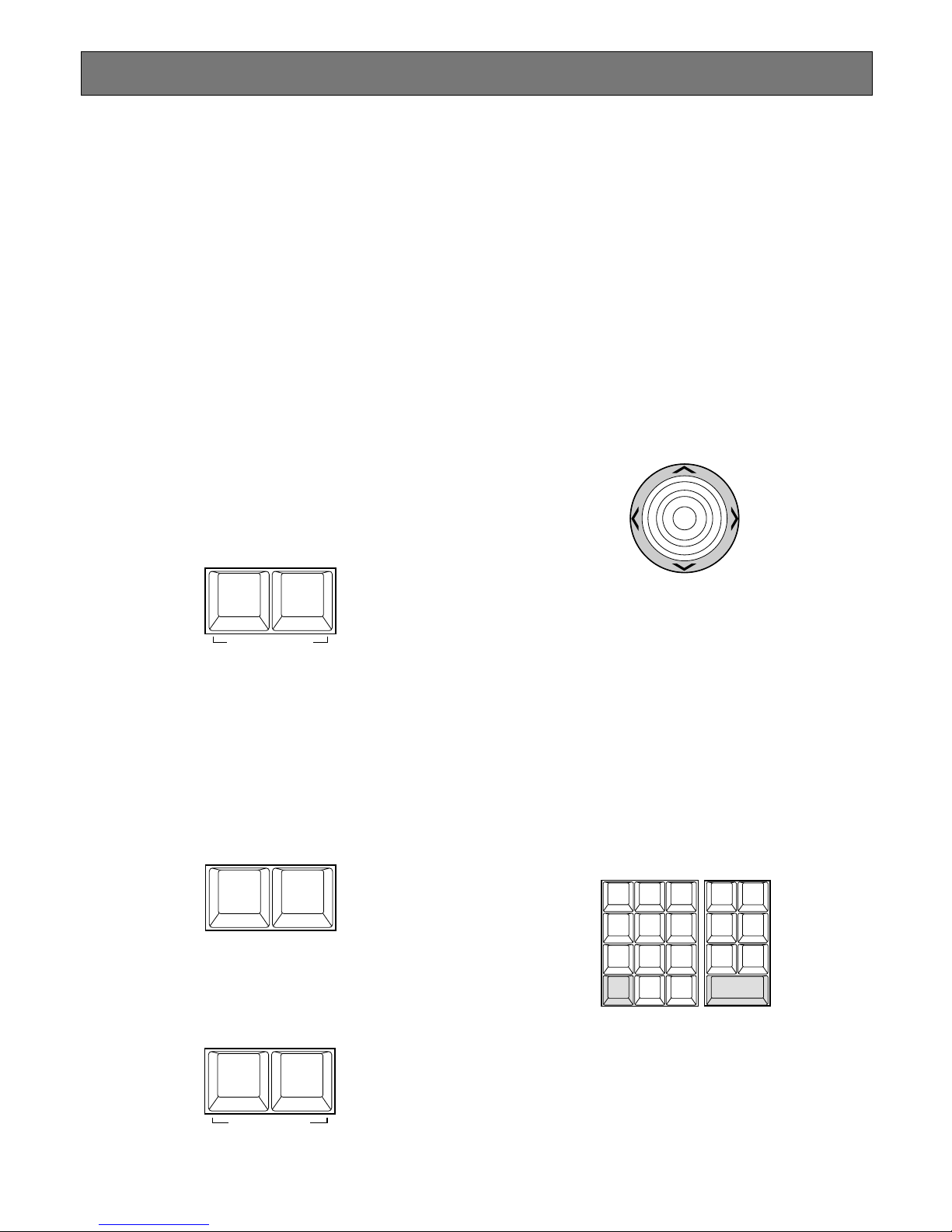
82
Controlling Camera Site Accessories
Controls for camera site accessories are located on the
right side of the front panel of the System Controller.
Included are Zoom Control, Focus Control, Iris Control,
Preset and Pan/Tilt Controls. Normally, combination cameras equipped with the specific feature or a WV-RC100 or
WV-RC150 Receiver are required to utilize these functions.
■ Lens Control
Note: Confirm that the specified lens, with power
zoom/focus functions, is mounted on the camera. Also
confirm that the Lens Selection (DC/VIDEO) on the
camera is set to the DC position.
Function capabilities vary between cameras. Referring
to the operating instructions of each camera is recommended.
1. Select the desired monitor and camera.
Refer to the Monitor Selection and Camera Selection.
2. Press the [FOCUS NEAR/FAR] keys while observing
the monitor to adjust the lens focus to achieve a
sharply focused picture.
By pressing these keys at the same time, the lens focus
is set automatically, if the specified camera with the
auto focus feature is used.
3. Press the [ZOOM TELE/WIDE] keys while observing
the monitor to adjust the lens zoom to achieve the
desired picture.
Press the [TELE] key to optically bring an object closer. Pressing the [WIDE] key has the reverse effect.
4. Press the [IRIS CLOSE/OPEN] keys to close/open the
lens iris. Adjust the lens iris by using these keys to
obtain the proper picture exposure.
By pressing these keys at the same time, the lens iris is
reset to the factory default setting.
■ Pan/Tilt Control
● Pan/Tilt Control (Manual Operation)
1. Select the desired monitor and camera.
Refer to the Monitor Selection and Camera Selection.
2. Move the Joystick Controller to move the Pan/Tilt Head
towards the desired direction.
If the joystick is positioned in between UP and R, the
Pan/Tilt Head moves diagonally towards Up and Right.
Eight directions are available: Up / Down / Right / Left /
Up-Right / Up-Left / Down-Right / Down-left.
3. Moving the Joystick Controller while holding down the
[SHIFT] key will move the Pan/Tilt Head step by step.
● Pan/Tilt Control (Auto Panning)
The following function requires the use of cameras
equipped with this specific feature.
1. Select the desired monitor and camera.
Refer to the Monitor Selection and Camera Selection.
2. Pressing the [CAMERA (ENTER)] key while holding
down the [SHIFT] key will activate the Auto Panning
function of the selected camera.
3. To cancel the auto panning function, move the Joystick
Controller.
NEAR FAR
AUTO FOCUS
FOCUS
WIDE TELE
ZOOM
CLOSE
WIPER
OPEN
DEFAULT
IRIS
UP
DOWN
R
L
LOGOUT
AUX1 OFF AUX1 ON
CALL
PRESET
PGM
PRESET
CAM
POSI
DIGITAL
OUT
DEF OFF DEF ON
AREA
AUX2 OFF AUX2 ON
CAMERA
(ENTER)
AUTO PAN
CAM ID
VLD S
T&D
ALM S
GEN
SYS S
(
ALARM
)
0
87
MSTA TUS
VLD H
ALL
ALM H
BLK
5964
231
SHIFT
CLEAR
(
ESC
)
EXIT
Page 79
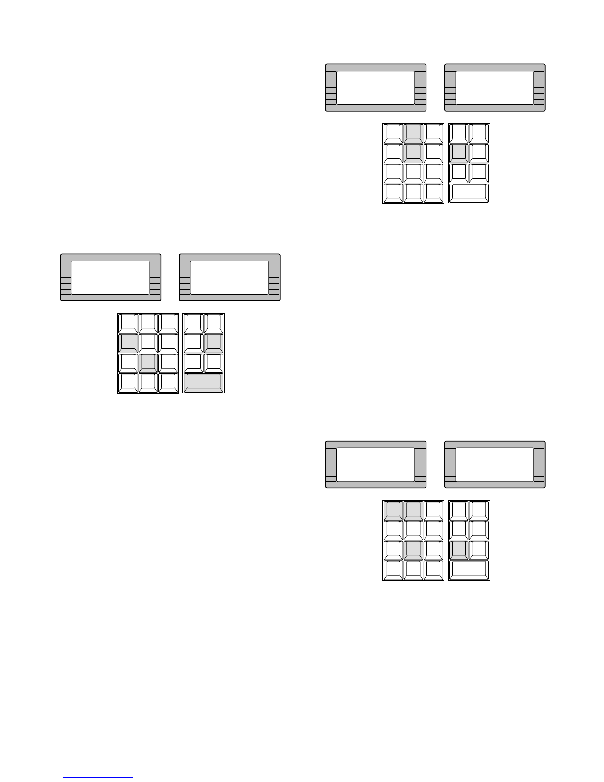
83
● Pan/Tilt Control
(Program Preset Position)
The following function requires the use of cameras
equipped with this specific feature.
1. Select the desired monitor and camera.
Refer to the Monitor Selection and Camera Selection.
2. Move the camera to the position to be preset by moving the Joystick Controller and pressing the lens control
keys.
3. Select the desired preset position number by pressing
the numeric keys.
4. Holding down the [PGM PRESET] key, and then press
the [CAMERA (ENTER)] key to save a preset position
of the camera.
Note: If the position number entered has been stored
previously, the old position will be overwritten by
the new one.
● Pan/Tilt Control (Call Preset Position)
The following function requires the use of cameras
equipped with this specific feature.
1. Select the desired monitor and camera.
Refer to the Monitor Selection and Camera Selection.
2. Select the preset position number by pressing the
numeric keys.
3. Press the [CALL PRESET] key to move to the preset
position of the selected camera on the active monitor.
Note: To be able to use the above function, the preset
position number must have been set for that camera.
● Pan/Tilt Control
(Camera Position Operation)
The following function requires the use of cameras
equipped with this specific feature.
1. Select the desired monitor.
Refer to the Monitor Selection.
2. Select the desired Camera Position Number by pressing the numeric keys, then press the [CAM POSI] key
to move the camera to the preset position.
The selected camera position appears on the active
monitor.
Note: To use the above function, it is necessary to reg-
ister the preset position number with the camera
number in the Administration Console in advance.
INFORMATION
Entry:48
INFORMATION
Prg Preset48
LOGOUT
AUX1 OFF AUX1 ON
CALL
PRESET
PGM
PRESET
CAM
POSI
DIGITAL
OUT
DEF OFF DEF ON
AREA
AUX2 OFF AUX2 ON
CAMERA
(ENTER)
AUTO PAN
CAM ID
VLD S
T&D
ALM S
GEN
SYS S
(
ALARM
)
0
87
MSTA TUS
VLD H
ALL
ALM H
BLK
5964
231
SHIFT
CLEAR
(
ESC
)
EXIT
INFORMATION
Entry:52
INFORMATION
Preset 52
LOGOUT
AUX1 OFF AUX1 ON
CALL
PRESET
PGM
PRESET
CAM
POSI
DIGITAL
OUT
DEF OFF DEF ON
AREA
AUX2 OFF AUX2 ON
CAMERA
(ENTER)
AUTO PAN
CAM ID
VLD S
T&D
ALM S
GEN
SYS S
(
ALARM
)
0
87
MSTA TUS
VLD H
ALL
ALM H
BLK
5964
231
SHIFT
CLEAR
(
ESC
)
EXIT
INFORMATION
Entry:128
INFORMATION
Cam Posi 128
LOGOUT
AUX1 OFF AUX1 ON
CALL
PRESET
PGM
PRESET
CAM
POSI
DIGITAL
OUT
DEF OFF DEF ON
AREA
AUX2 OFF AUX2 ON
CAMERA
(ENTER)
AUTO PAN
CAM ID
VLD S
T&D
ALM S
GEN
SYS S
(
ALARM
)
0
87
MSTA TUS
VLD H
ALL
ALM H
BLK
5964
231
SHIFT
CLEAR
(
ESC
)
EXIT
Page 80
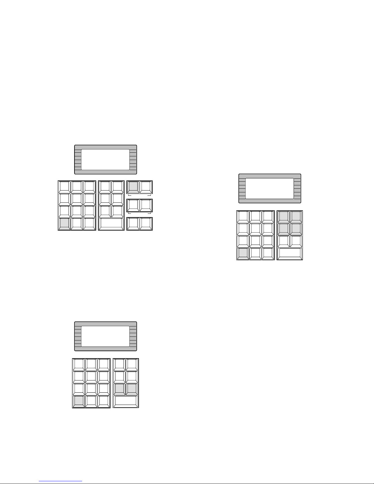
84
■ Receiver Control
● Camera Housing Control
The following function is available only when the WVRC100 or WV-RC150 Receivers are included in the system and the specified camera housing is installed.
• Wiper Control
1. Select the desired monitor and camera.
Refer to the Monitor Selection and Camera
Selection.
2. Pressing the [IRIS CLOSE] key while holding down
the [SHIFT] key will turn on the Housing Wiper of
the camera until the keys are released.
• Defroster Control
1. Select the desired monitor and camera.
Refer to the Monitor Selection and Camera
Selection.
2. Pressing the [DIGITAL OUT] key while holding
down the [SHIFT] key will turn on the housing
defroster of the camera.
To turn off the defroster, pressing the [CAM POSI]
key while holding down the [SHIFT] key.
● Auxiliary Control
The following function is available only when the WVRC100 or WV-RC150 Receivers are included in the system.
1. Select the desired monitor and camera.
Refer to the Monitor Selection and Camera Selection.
2. Pressing the [AREA] key while holding down the
[SHIFT] key will turn on the user’s auxiliary switch 1 of
the Receiver.
Pressing the [LOG OUT] key holding down the [SHIFT]
key will turn off the user’s auxiliary switch 1 of the
Receiver.
3. Press the [PGM PRESET] key while holding down the
[SHIFT] key will turn on the user’s auxiliary switch 2 of
the Receiver.
Pressing the [CALL PRESET] key while holding down
the [SHIFT] key will turn off the user’s auxiliary switch 2
of the Receiver.
INFORMATION
Wiper On
CAM ID
VLD S
T&D
ALM S
GEN
SYS S
(
ALARM
)
0
87
MSTA TUS
VLD H
ALL
ALM H
BLK
5964
231
SHIFT
CLEAR
(
ESC
)
EXIT
LOGOUT
AUX1 OFF AUX1 ON
CALL
PRESET
PGM
PRESET
CAM
POSI
DIGITAL
OUT
CAMERA
(ENTER)
DEF OFF
AUTO PAN
DEF ON
AREA
AUX2 OFF AUX2 ON
CLOSE
IRIS
WIPER
OPEN
NEAR FAR
WIDE TELE
AUTO FOCUS
ZOOM
DEFAULT
FOCUS
INFORMATION
Def On
LOGOUT
AUX1 OFF AUX1 ON
CALL
PRESET
PGM
PRESET
CAM
POSI
DIGITAL
OUT
DEF OFF DEF ON
AREA
AUX2 OFF AUX2 ON
CAMERA
(ENTER)
AUTO PAN
CAM ID
VLD S
T&D
ALM S
GEN
SYS S
(
ALARM
)
0
87
MSTA TUS
VLD H
ALL
ALM H
BLK
5964
231
SHIFT
CLEAR
(
ESC
)
EXIT
INFORMATION
Aux1 On
LOGOUT
AUX1 OFF AUX1 ON
CALL
PRESET
PGM
PRESET
CAM
POSI
DIGITAL
OUT
DEF OFF DEF ON
AREA
AUX2 OFF AUX2 ON
CAMERA
(ENTER)
AUTO PAN
CAM ID
VLD S
T&D
ALM S
GEN
SYS S
(
ALARM
)
0
87
MSTA TUS
VLD H
ALL
ALM H
BLK
5964
231
SHIFT
CLEAR
(
ESC
)
EXIT
Page 81
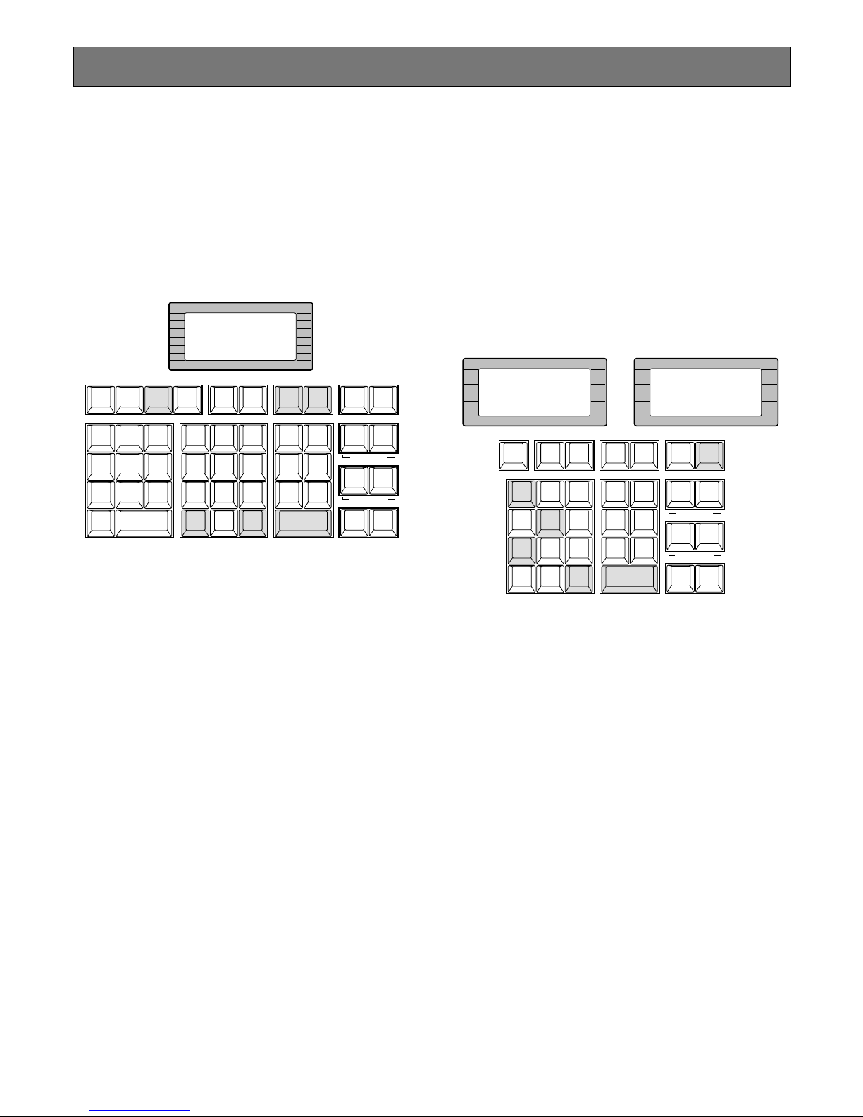
85
Camera Function Control
■ Camera Setup
The following function requires the use of cameras
equipped with this specific feature.
1. Select the desired monitor and camera.
Refer to the Monitor Selection and Camera Selection.
2. Pressing the [F4] key while holding down the [SHIFT]
key will gain access to the Camera Setup Menu display
on the active monitor.
3. Select the desired item in the menu by moving the
Joystick Controller UP and DOWN, and then select the
desired parameter (or mode) in the menu by moving
the Joystick Controller L and R.
Press the [CAMERA (ENTER)] key to execute the currently highlighted selection and to enter a submenu of
the Camera Setup Menu, or press the [CLEAR (ESC)]
key to leave the currently selected menu and return to
the previous page of the menu.
4. Press the [RESET] key in the menu to reset the parameter of a selected item to the factory default setting or
enter the Special Camera Menu when the cursor is
positioned on SPECIAL in the menu.
Pressing the [RESET] key while holding down the
[SHIFT] key will restore all factory default settings.
Notes:
• Refer to the Operating Instructions of the selected
camera for more details.
• Moving the joystick while holding down the [SHIFT]
key will move the camera smoothly for presetting
the position in the camera setup menu.
5. To close the Camera Setup Menu, press the [F3] key
while holding down the [SHIFT] key.
■ Camera Function (Shortcut
Function)
The following function is available only when specified cameras with the camera function feature are used.
This function enables executing camera functions via a
shortcut.
1. Select the desired monitor and camera.
Refer to the Monitor Selection and Camera Selection.
2. Press the [F6] key.
“Camera Function” as shown in the figure will appear
on the LCD display of the controller.
3. Select an assigned function number by pressing the
numeric keys, then press the [CAMERA (ENTER)] key.
For example, enter 175 for AGC On.
The selected function will be executed on the active
monitor.
Note: For further information, refer to the Operating
Instructions for that camera.
4. To exit from the mode, press the [CLEAR (ESC)] key.
INFORMATION
Cam Menu On
ALARM
ACK
RESET
ALL
RESET
ARM
GROUP
PRESET
PREV
S-CTL IDOPE ID
NEXT
GROUP
SEQ
PAUSE STOP
TOUR
SEQ
REV
RUN
FWD
RUN
OSD
F.1 F.2 F. 3
CMENU
OFF
F.4
CMENU
ON
F.5 F.6
CLOSE
IRIS
WIPER
OPEN
NEAR FAR
WIDE TELE
AUTO FOCUS
ZOOM
MONITOR
LOCK
OSD SERVICE
LOGOUT
AUX1 OFF AUX1 ON
CALL
PRESET
PGM
PRESET
CAM
POSI
DIGITAL
OUT
CAM ID
VLD S
T&D
ALM S
GEN
SYS S
(
ALARM
)
0
87
DEF OFF DEF ON
MSTA TUS
VLD H
ALL
ALM H
BLK
5964
231
SHIFT
CLEAR
(
ESC
)
EXIT
AREA
AUX2 OFF AUX2 ON
DEFAULT
FOCUS
VER
CAM
FUNC
CAMERA
(ENTER)
AUTO PAN
INFORMATION
Camera Function
-----
INFORMATION
Camera Function
--175
ARM
F.1 F.2 F. 3
CMENU
OFF
F.4
CMENU
ON
F.5 F.6
CLOSE
IRIS
WIPER
OPEN
NEAR FAR
WIDE TELE
AUTO FOCUS
ZOOM
LOGOUT
AUX1 OFF AUX1 ON
CALL
PRESET
PGM
PRESET
CAM
POSI
DIGITAL
OUT
CAM ID
VLD S
T&D
ALM S
GEN
SYS S
(
ALARM
)
0
87
DEF OFF DEF ON
MSTA TUS
VLD H
ALL
ALM H
BLK
5964
231
SHIFT
CLEAR
(
ESC
)
EXIT
AREA
AUX2 OFF AUX2 ON
DEFAULT
FOCUS
CAM
FUNC
CAMERA
(ENTER)
AUTO PAN
Page 82
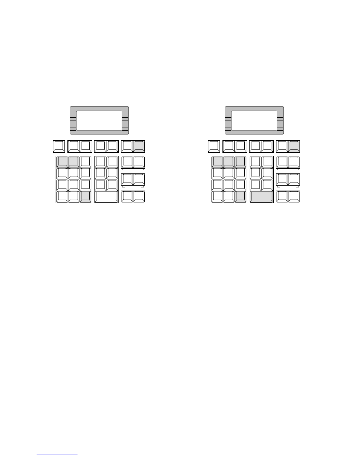
86
■ Changing to Black and White
Pictures
The following function is available only when specified cameras having a color-black and white switching feature are
used.
1. Select the desired monitor and camera.
Refer to the Monitor Selection and Camera Selection.
2. Press the [F6] key two times.
“B/W Change” as shown in the figure will appear on
the LCD display of the controller.
3. Press the [1] key to change the picture from color to
black and white on the active monitor.
4. Press the [2] key to change black and white to color
picture on the active monitor.
5. To exit from the mode, press the [CLEAR (ESC)] key.
Note: When the black and white parameter is set
AUTO in the camera setup menu, this function is
disabled.
■ Patrol Learn and Play
The following function requires the use of cameras
equipped with this specific feature.
A routine of manual operations can be stored for a specific
time and later reproduced repetitively.
1. Select the desired monitor and camera.
Refer to the Monitor Selection and Camera Selection.
2. Press the [F6] key three times.
“Patrol Learn” as shown in the figure will appear on the
LCD display of the controller.
To save the patrol sequence, follow the procedure
shown below.
q Press the [2] key, then press the [CAMERA
(ENTER)] key to start Patrol Learn.
w Operate the camera manually. Operations data
(patrol sequence) is stored.
e Press the [3] key to end the learning.
To reproduce the stored data, follow the procedure
shown below.
q Press the [1] key to reproduce the stored Patrol
function.
w Press the [3] key to end the reproduction.
3. To exit from the mode, press the [CLEAR (ESC)] key.
INFORMATION
B/W change
1:On
2:Off
ARM
F.1 F.2 F. 3
CMENU
OFF
F.4
CMENU
ON
F.5 F.6
CLOSE
IRIS
WIPER
OPEN
NEAR FAR
WIDE TELE
AUTO FOCUS
ZOOM
LOGOUT
AUX1 OFF AUX1 ON
CALL
PRESET
PGM
PRESET
CAM
POSI
DIGITAL
OUT
CAM ID
VLD S
T&D
ALM S
GEN
SYS S
(
ALARM
)
0
87
DEF OFF DEF ON
MSTA TUS
VLD H
ALL
ALM H
BLK
5964
231
SHIFT
CLEAR
(
ESC
)
EXIT
AREA
AUX2 OFF AUX2 ON
DEFAULT
FOCUS
CAM
FUNC
CAMERA
(ENTER)
AUTO PAN
INFORMATION
Patrol Learn
1:Play
2:Learn(2+Enter)
3:Stop
ARM
F.1 F.2 F. 3
CMENU
OFF
F.4
CMENU
ON
F.5 F.6
CLOSE
IRIS
WIPER
OPEN
NEAR FAR
WIDE TELE
AUTO FOCUS
ZOOM
LOGOUT
AUX1 OFF AUX1 ON
CALL
PRESET
PGM
PRESET
CAM
POSI
DIGITAL
OUT
CAM ID
VLD S
T&D
ALM S
GEN
SYS S
(
ALARM
)
0
87
DEF OFF DEF ON
MSTA TUS
VLD H
ALL
ALM H
BLK
5964
231
SHIFT
CLEAR
(
ESC
)
EXIT
AREA
AUX2 OFF AUX2 ON
DEFAULT
FOCUS
CAM
FUNC
CAMERA
(ENTER)
AUTO PAN
Page 83
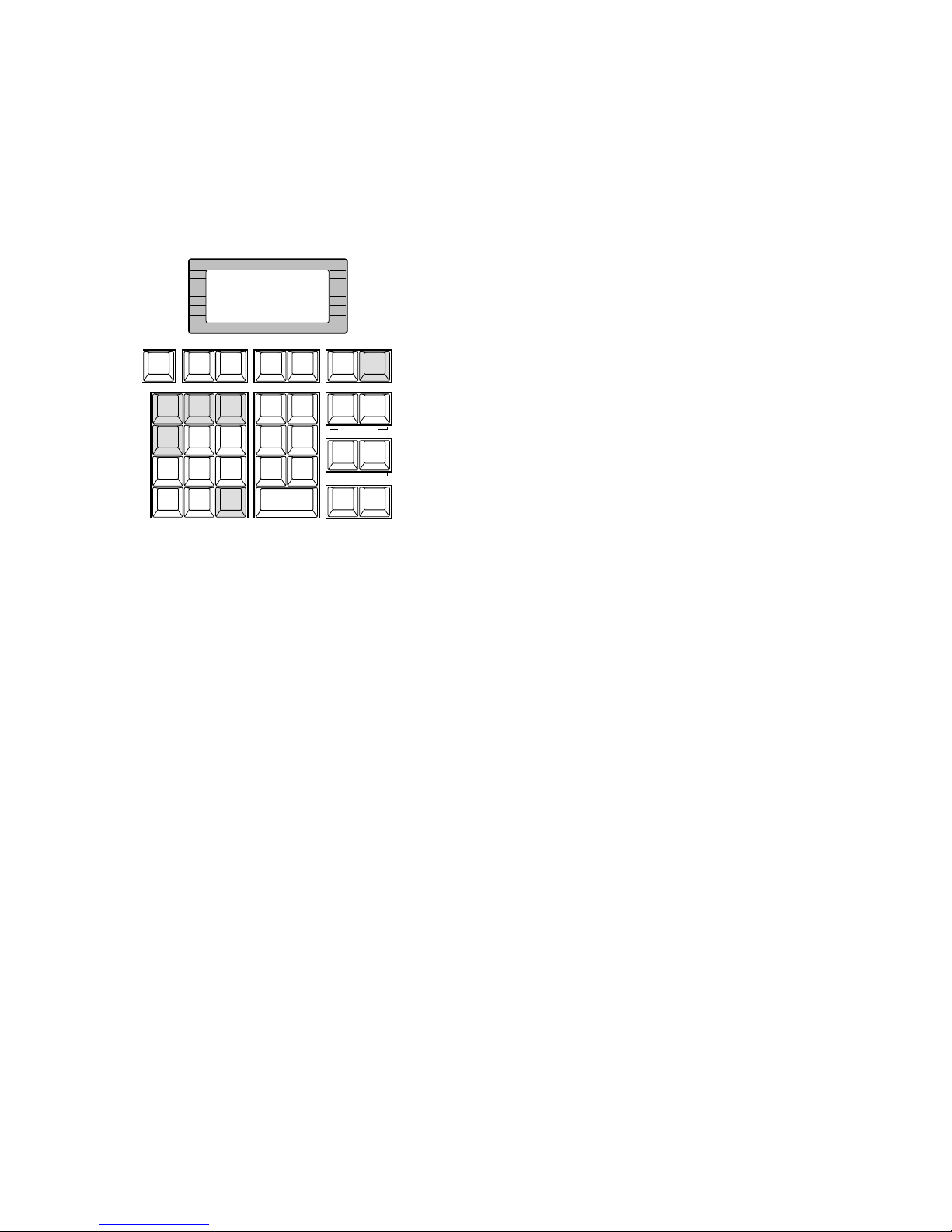
87
■ Camera Panning Function
The following function requires the use of cameras
equipped with this specific feature.
1. Select the desired monitor and camera.
Refer to the Monitor Selection and Camera Selection.
2. Press the [F6] key four times.
“Pan Action” as shown in the figure will appear on the
LCD display of the controller.
3. Press the assigned numeric key shown below to activate the panning function of the selected camera.
1: Activates Auto Pan.
2: Activates Sort Pan.
3: Activates Sequence Pan.
4: Activates Random Pan.
Note: The AUTO MODE parameter previously set in the
camera setup menu will be automatically replaced
to the activated function parameter.
4. To exit from the mode, press the [CLEAR (ESC)] key.
INFORMATION
Pan Action
1:Pan 3:seq
2:Sort 4:Random
ARM
F.1 F.2 F. 3
CMENU
OFF
F.4
CMENU
ON
F.5 F.6
CLOSE
IRIS
WIPER
OPEN
NEAR FAR
WIDE TELE
AUTO FOCUS
ZOOM
LOGOUT
AUX1 OFF AUX1 ON
CALL
PRESET
PGM
PRESET
CAM
POSI
DIGITAL
OUT
CAM ID
VLD S
T&D
ALM S
GEN
SYS S
(
ALARM
)
0
87
DEF OFF DEF ON
MSTA TUS
VLD H
ALL
ALM H
BLK
5964
231
SHIFT
CLEAR
(
ESC
)
EXIT
AREA
AUX2 OFF AUX2 ON
DEFAULT
FOCUS
CAM
FUNC
CAMERA
(ENTER)
AUTO PAN
Page 84
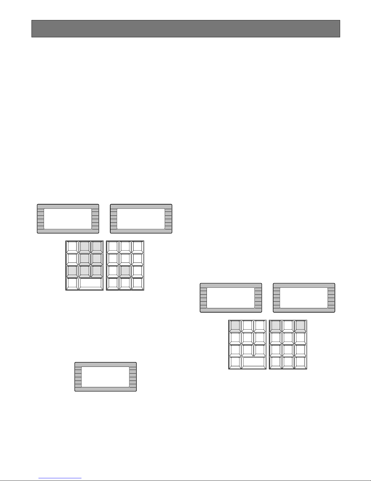
88
Running Sequence
■ Tour Sequence
The following functions are available only if a Tour
Sequence has been previously established through the
Administration Console. As described on the setup, any of
the tours can be assigned to any of the monitors.
1. Select the desired monitor.
Refer to the Monitor Selection.
2. Select the desired Tour Sequence Number by pressing
the numeric keys.
3. Pressing the [FWD RUN] key while holding down the
[TOUR SEQ] key will run the tour sequence in forward
direction on the active monitor, or pressing the [REV
RUN] key while holding down the [TOUR SEQ] key will
run the tour sequence in reverse direction on the active
monitor.
The selected Tour Sequence Number (T8) with “R” sign
(indicate running status) is displayed on the active
monitor.
Note: By the factory default setting, pressing the
[TOUR SEQ] key after numeric input will run the
selected Tour Sequence forward.
4. Press the [PAUSE] key to pause a Tour Sequence that
is being run on the active monitor.
The “P” sign (indicating the pause status) is displayed
at the Tour Sequence Number on the active monitor.
5. Press the [FWD RUN] key to restart a Tour Sequence
forward from the next step that was previously paused
by pressing the PAUSE key.
6. Press the [REV RUN] key to restart a Tour Sequence
backward from the next step that was previously
paused by pressing the PAUSE key.
7. Press the [NEXT] key to move the sequence one frame
to the next step (in forward or reverse run direction)
from the step that was previously paused by pressing
the PAUSE key.
8. Press the [PREV] key to move the sequence one frame
to the previous step (in forward or reverse run direction) from the step that was previously paused by
pressing the PAUSE key.
9. To return to Spot monitoring, press the [STOP] key to
end a Tour Sequence that is being run on the active
monitor.
■ Call Group Preset
The following function is available only if a Group Preset
has been previously established through the Administration
Console.
1. As described earlier, a Group Preset determines which
monitor is to be assigned to which camera. Therefore,
selecting a monitor is not required.
2. Select a desired Group Preset Number by pressing the
Numeric keys.
3. Press the [GROUP PRESET] key to activate a selected
Group Preset function.
The selected preset position of the cameras is displayed on the assigned monitors at a time.
INFORMATION
Entry:8
INFORMATION
Seq 8 Fwd Run
CAM ID
VLD S
T&D
ALM S
GEN
SYS S
(
ALARM
)
0
87
MSTA TUS
VLD H
ALL
ALM H
BLK
5964
231
SHIFT
CLEAR
(
ESC
)
EXIT
GROUP
PRESET
PREV
S-CTL IDOPE ID
NEXT
GROUP
SEQ
PAUSE STOP
TOUR
SEQ
REV
RUN
FWD
RUN
OSD
VER
MONITOR
LOCK
OSD SERVICE
INFORMATION
Seq 8 Pause
INFORMATION
Entry:13
INFORMATION
Group Preset 13
CAM ID
VLD S
T&D
ALM S
GEN
SYS S
(
ALARM
)
0
87
MSTA TUS
VLD H
ALL
ALM H
BLK
5964
231
SHIFT
CLEAR
(
ESC
)
EXIT
GROUP
PRESET
PREV
S-CTL IDOPE ID
NEXT
GROUP
SEQ
PAUSE STOP
TOUR
SEQ
REV
RUN
FWD
RUN
OSD
VER
MONITOR
LOCK
OSD SERVICE
Page 85
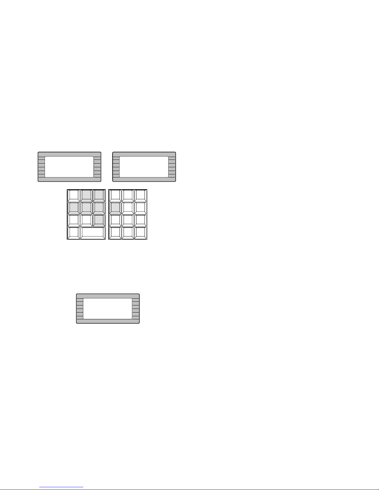
89
■ Group Sequence
The following function is available only if a Group Sequence
has been previously established through the Administration
Console.
1. As described earlier, a Group Sequence determines
which monitor is to be assigned to which camera.
Therefore, selecting a monitor is not required.
2. Select a desired Group Sequence Number by pressing
the Numeric keys.
3. Press the [GROUP SEQ] key to run a group sequence
forward on the assigned monitors.
The selected Group Sequence Number (G4) with “R”
sign (indicate running status) is displayed on the active
monitor.
4. To pause the sequence, select one of the monitors that
are being run on the selected group sequence, then
press the [PAUSE] key.
The “P” sign (indicating the pause status) is displayed
at the Group Sequence Number on the assigned monitor.
5. Press the [FWD RUN] key to restart a Group Sequence
forward from the next step that was previously paused
by pressing the PAUSE key.
6. Press the [NEXT] key to move the sequence one frame
to the next step from the step that was previously
paused by pressing the PAUSE key.
7. Press the [PREV] key to move the sequence one frame
to the previous step from the step that was previously
paused by pressing the PAUSE key.
8. To stop the sequence, select one of the monitors that
are being run on the selected group sequence, then
press the [STOP] key.
INFORMATION
Entry:4
INFORMATION
Grp Seq 4 Fwd Run
CAM ID
VLD S
T&D
ALM S
GEN
SYS S
(
ALARM
)
0
87
MSTA TUS
VLD H
ALL
ALM H
BLK
5964
231
SHIFT
CLEAR
(
ESC
)
EXIT
GROUP
PRESET
PREV
S-CTL IDOPE ID
NEXT
GROUP
SEQ
PAUSE STOP
TOUR
SEQ
REV
RUN
FWD
RUN
OSD
VER
MONITOR
LOCK
OSD SERVICE
INFORMATION
Grp Seq 4 Pause
Page 86
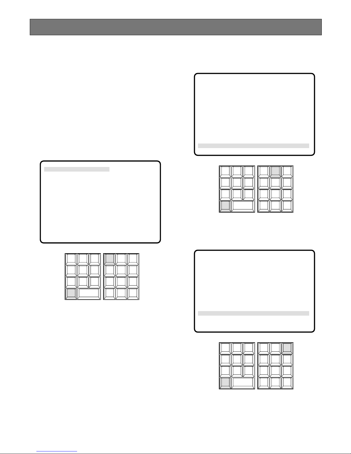
90
■ On-Screen Display Control
The procedure described below lets you determine the display, such as camera title, clock and status, on and off on
the active monitor screen.
Note: The following functions are not available when the
on-screen displays are compounded from the
Character Board that is installed on the Camera Input
Board. Confirm the setting in the Administration
Console for details.
1. Select the desired monitor.
Refer to the Monitor Selection.
2. Pressing the [1] key while holding down the [OSD] key
will toggle the clock (time and date) display on the
active monitor on and off.
3. Pressing the [2] key while holding down the [OSD] key
will toggle the camera number and title display on the
active monitor on and off.
4. Pressing the [3] key while holding down the [OSD] key
will toggle the general status display on the active monitor on and off.
Monitor Display Control
07/07/1999 03:37:21 PM
M■■■■■ AREA1 ALM T■■■ R A■■■
C■■■■■ CAMERA TITLE
CAM ID
VLD S
T&D
ALM S
GEN
SYS S
(
ALARM
)
0
87
MSTA TUS
VLD H
ALL
ALM H
BLK
5964
231
SHIFT
CLEAR
(
ESC
)
EXIT
GROUP
PRESET
PREV
S-CTL IDOPE ID
NEXT
GROUP
SEQ
PAUSE STOP
TOUR
SEQ
REV
RUN
FWD
RUN
OSD
VER
MONITOR
LOCK
OSD SERVICE
07/07/1999 03:37:21 PM
M■■■■■ AREA1 ALM T■■■ R A■■■
C■■■■■ CAMERA TITLE
CAM ID
VLD S
T&D
ALM S
GEN
SYS S
(
ALARM
)
0
87
MSTA TUS
VLD H
ALL
ALM H
BLK
5964
231
SHIFT
CLEAR
(
ESC
)
EXIT
GROUP
PRESET
PREV
S-CTL IDOPE ID
NEXT
GROUP
SEQ
PAUSE STOP
TOUR
SEQ
REV
RUN
FWD
RUN
OSD
VER
MONITOR
LOCK
OSD SERVICE
07/07/1999 03:37:21 PM
M■■■■■ AREA1 ALM T■■■ R A■■■
C■■■■■ CAMERA TITLE
CAM ID
VLD S
T&D
ALM S
GEN
SYS S
(
ALARM
)
0
87
MSTA TUS
VLD H
ALL
ALM H
BLK
5964
231
SHIFT
CLEAR
(
ESC
)
EXIT
GROUP
PRESET
PREV
S-CTL IDOPE ID
NEXT
GROUP
SEQ
PAUSE STOP
TOUR
SEQ
REV
RUN
FWD
RUN
OSD
VER
MONITOR
LOCK
OSD SERVICE
Page 87
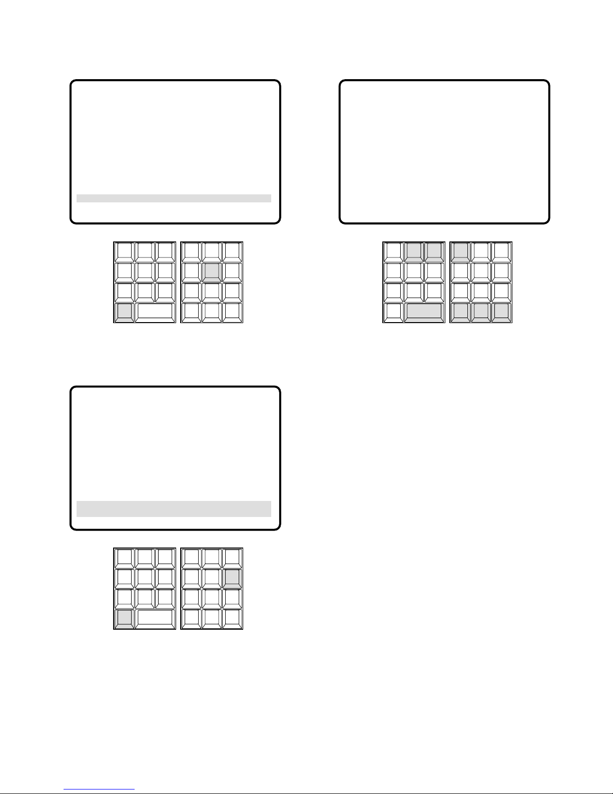
91
5. Pressing the [5] key while holding down the [OSD] key
will toggle the monitor status display on the active monitor on and off.
6. Pressing the [6] key while holding down the [OSD] key
will toggle the display except clock (time and date) on
the active monitor on and off.
■ Alarm Status Table
The table shows each alarm status up to 1 024 alarms on
the active monitor screen.
1. Select a monitor for displaying the status.
Refer to the Monitor Selection.
2. Pressing the [1] key while holding down the [MONI-
TOR] key will display the ALARM STATUS table as
shown in the figure on the active monitor.
The columns in the table indicate the states as shown
below.
ALM: Logical Alarm Number
STATE: Indicates alarm state changes.
ARMED: The system is armed for alarm response.
ACTIVE: Alarm has been triggered and activated
assigned alarm response.
ACKED: Alarm is acknowledged and an operator
can control the alarm action.
RESET: Activated alarm is reset, but the alarm
device is still active.
DISARMED: The system is disarmed for alarm
response.
NAME: Alarm Text
3. Press the [NEXT] key to select the next page of the
table, and press the [PREV] key to back up to the previous page.
4. Press the [NEXT] key while holding down the [SHIFT]
key to select the first page of the table, and press the
[PREV] key while holding down the [SHIFT] key to
select the last page.
5. Pressing the [0] key while holding down the [MONI-
TOR] key will toggle the background camera images
and black on the active monitor.
6. To exit as it stands, select a new monitor.
7. To exit from the mode, press the [CLEAR (ESC)] key
while holding down the [MONITOR] key or select a
camera to be displayed on the active monitor.
07/07/1999 03:37:21 PM
M■■■■■ AREA1 ALM T■■■ R A■■■
C■■■■■ CAMERA TITLE
CAM ID
VLD S
T&D
ALM S
GEN
SYS S
(
ALARM
)
0
87
MSTA TUS
VLD H
ALL
ALM H
BLK
5964
231
SHIFT
CLEAR
(
ESC
)
EXIT
GROUP
PRESET
PREV
S-CTL IDOPE ID
NEXT
GROUP
SEQ
PAUSE STOP
TOUR
SEQ
REV
RUN
FWD
RUN
OSD
VER
MONITOR
LOCK
OSD SERVICE
ALARM STATUS PG 1
ALM STATE NAME
1 ARMED Alarm1
2 ACK Alarm2
3 ACK
4 ACK
5 ACTIVE
6 ACTIVE
7 ARMED
8 ARMED
9 ARMED
10 ARMED
CAM ID
VLD S
T&D
ALM S
GEN
SYS S
(
ALARM
)
0
87
MSTA TUS
VLD H
ALL
ALM H
BLK
5964
231
SHIFT
CLEAR
(
ESC
)
EXIT
GROUP
PRESET
PREV
S-CTL IDOPE ID
NEXT
GROUP
SEQ
PAUSE STOP
TOUR
SEQ
REV
RUN
FWD
RUN
OSD
VER
MONITOR
LOCK
OSD SERVICE
07/07/1999 03:37:21 PM
M■■■■■ AREA1 ALM T■■■ R A■■■
C■■■■■ CAMERA TITLE
CAM ID
VLD S
T&D
ALM S
GEN
SYS S
(
ALARM
)
0
87
MSTA TUS
VLD H
ALL
ALM H
BLK
5964
231
SHIFT
CLEAR
(
ESC
)
EXIT
GROUP
PRESET
PREV
S-CTL IDOPE ID
NEXT
GROUP
SEQ
PAUSE STOP
TOUR
SEQ
REV
RUN
FWD
RUN
OSD
VER
MONITOR
LOCK
OSD SERVICE
Page 88
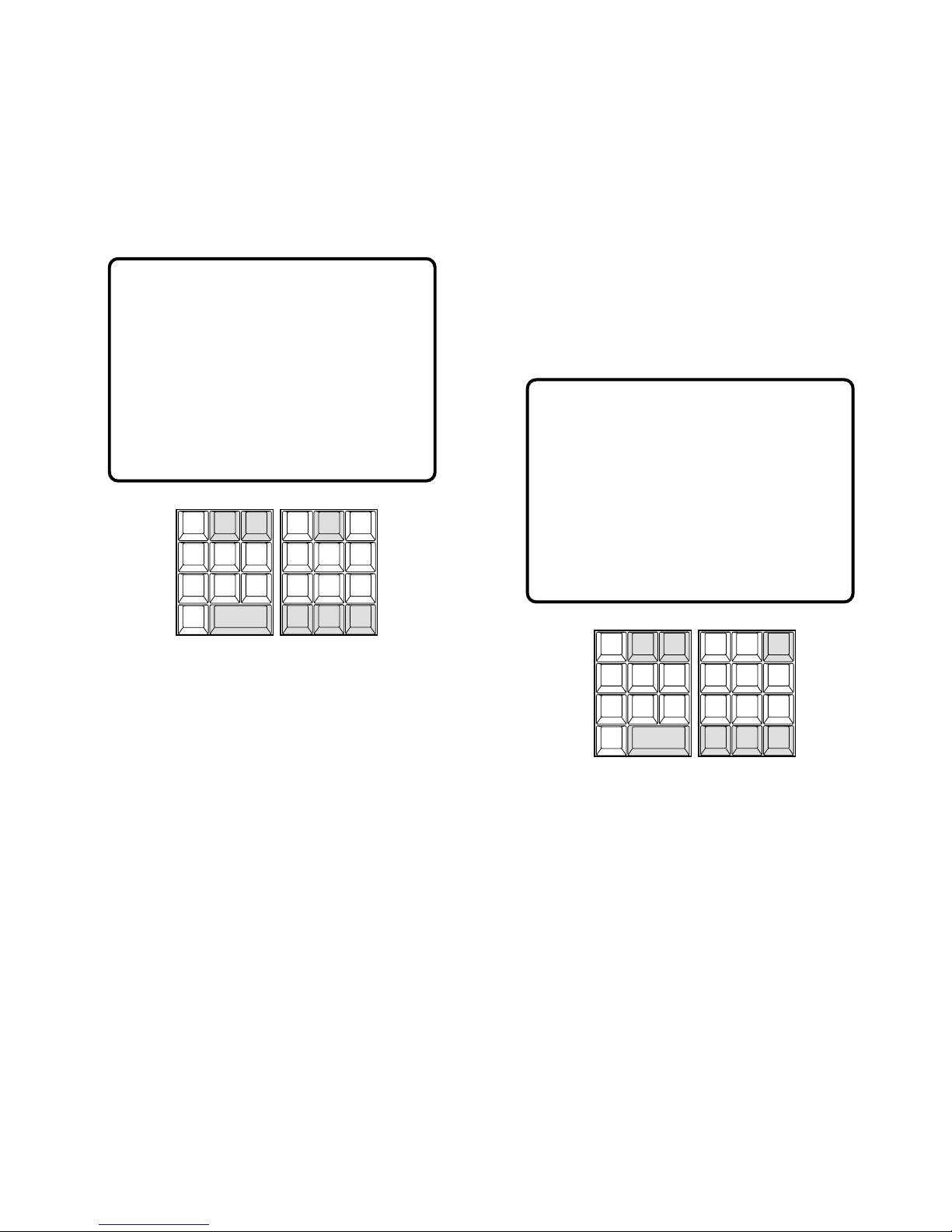
92
■ Video Loss Status Table
The table shows the video loss detection status up to 1 024
MXCONT inputs on the active monitor.
1. Select a monitor for displaying the status.
Refer to the Monitor Selection.
2. Pressing the [2] key while holding down the [MONI-
TOR] key will the display the VIDEO LOSS STATUS
table as shown in the figure on the active monitor.
The columns in the table indicate the states as shown
below.
CAM: Logical Camera Number
PORT#: Video Input Port Number
STATUS:
ABOVE/IN: Video level is above normal and in
sync.
BELOW/IN: Video level is below normal and in
sync.
ABOVE/OUT: Video level is above normal and out
of sync.
BELOW/OUT: Video level is below normal and out
of sync.
LOCATION: Logical cage number that the port
belongs to.
3. Press the [NEXT] key to select the next page of the status, and press the [PREV] key to back up to the previous page.
4. Press the [NEXT] key while holding down the [SHIFT]
key to select the first page of the status, and press the
[PREV] key while holding down the [SHIFT] key to
select the last page.
5. Pressing the [0] key while holding down the [MONI-
TOR] key will toggle the background camera images
and black on the active monitor.
6. To exit as it stands, select a new monitor.
7. To exit from the mode, press the [CLEAR (ESC)] key
while holding down the [MONITOR] key or select a
camera to be displayed on the active monitor.
■ System Status Table
The table shows the system status in real time.
1. Select a monitor for displaying the status.
Refer to the Monitor Selection.
2. Pressing the [3] key while holding down the [MONI-
TOR] key will display the SYSTEM STATUS table as
shown in the figure on the active monitor.
The columns in the table indicate the states as shown
below.
MON: Monitor Number
ARE: Area Number
CAM: Logical Camera Number
No number indicates no camera selection.
SEQ: Running sequence number
T: Tour Sequence
G: Group Sequence
No number indicates the camera is selected in
spot.
"R" and "P" indicate the status of "Running" and
"Paused".
DEV: Device Name
K: System Controller number with normal user
operator.
S: System Controller number with super user oper-
ator.
ALM: Alarm
EVT: Timer Event
VIDEO LOSS STATUS PG 1
CAM PORT# STATUS LOCATION
1 1 ABOVE/IN FRAME1
2 2 BELOW/OUT FRAME1
3 3 ABOVE/IN FRAME1
4 4 BELOW/OUT FRAME1
5 5 ABOVE/IN FRAME1
6 6 ABOVE/IN FRAME1
7 7 ABOVE/IN FRAME1
8 8 ABOVE/IN FRAME1
9 9 ABOVE/IN FRAME1
10 10 ABOVE/IN FRAME1
CAM ID
VLD S
T&D
ALM S
GEN
SYS S
(
ALARM
)
0
87
MSTA TUS
VLD H
ALL
ALM H
BLK
5964
231
SHIFT
CLEAR
(
ESC
)
EXIT
GROUP
PRESET
PREV
S-CTL IDOPE ID
NEXT
GROUP
SEQ
PAUSE STOP
TOUR
SEQ
REV
RUN
FWD
RUN
OSD
VER
MONITOR
LOCK
OSD SERVICE
MON ARE CAM SEQ DEV USRID PRTY
1 0 2 T1 P ALM 20 5
2 0 3 - S4 101 6
3 0 - - K2 105 65535
4 0 10001 - - - 5 0 1 T1001R K3 106 8
6 0 - G2 P K128 - 7 0 - G2 P K128 - : : - - - - 1023 128 - - - - 9999 128 - - - - -
CAM ID
VLD S
T&D
ALM S
GEN
SYS S
(
ALARM
)
0
87
MSTA TUS
VLD H
ALL
ALM H
BLK
5964
231
SHIFT
CLEAR
(
ESC
)
EXIT
GROUP
PRESET
PREV
S-CTL IDOPE ID
NEXT
GROUP
SEQ
PAUSE STOP
TOUR
SEQ
REV
RUN
FWD
RUN
OSD
VER
MONITOR
LOCK
OSD SERVICE
Page 89
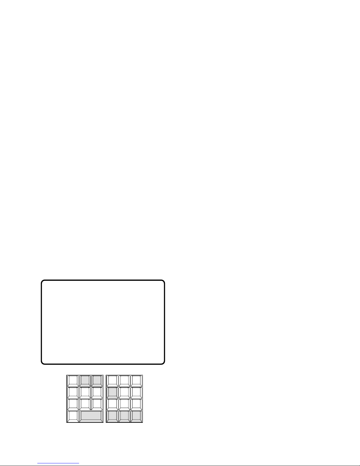
93
USRID: User ID
Note: Alarm USRID consists of Alarm Number and
Alarm Action Number.
E.g. “ALM20” indicates alarm #2 and its action #0.
PRTY: User Priority
3. Press the [NEXT] key to select the next page of the status, and press the [PREV] key to back up to the previous page.
4. Press the [NEXT] key while holding down the [SHIFT]
key to select the first page of the status, and press the
[PREV] key while holding down the [SHIFT] key to
select the last page.
5. Pressing the [0] key while holding down the [MONI-
TOR] key will toggle the background camera images
and black on the active monitor.
6. To exit as it stands, select a new monitor.
7. To exit from the mode, press the [CLEAR (ESC)] key
while holding down the [MONITOR] key or select a
camera to be displayed on the active monitor.
■ Alarm History Table
There are 100 alarm records stored in chronological order
in 10 pages of table.
1. Select a monitor for displaying the history.
Refer to the Monitor Selection.
2. Pressing the [4] key while holding down the [MONI-
TOR] key will display the ALARM HISTORY table as
shown in the figure on the active monitor.
The columns in the table indicate the states as shown
below.
ALM: Logical Alarm Number
STATE: Indicates alarm state changes.
ARMED: The system is armed for alarm response.
ACTIVE: Alarm has been triggered and activated
assigned alarm response.
ACKED: Alarm is acknowledged and an operator
can control the alarm action.
RESET: Activated alarm is reset, but the alarm
device is still active.
DISARMED: The system is disarmed for alarm
response.
DATE-TIME: Date and time when alarm state changes.
3. Press the [NEXT] key to select the next page of the history, and press the [PREV] key to back up to the previous page.
4. Press the [NEXT] key while holding down the [SHIFT]
key to select the first page of the history, and press the
[PREV] key while holding down the [SHIFT] key to
select the last page.
5. Pressing the [0] key while holding down the [MONI-
TOR] key will toggle the background camera images
and black on the active monitor.
6. To exit as it stands, select a new monitor.
7. To exit from the mode, press the [CLEAR (ESC)] key
while holding down the [MONITOR] key or select a
camera to be displayed on the active monitor.
ALARM HISTORY PG 1
ALM STATE DATE-TIME
2 ARMED 03/21/00 10:17
2 ACKED 03/21/00 10:16
2 ACTIVE 03/21/00 10:15
1 ARMED 03/21/00 10:14
1 ACTIVE 03/21/00 10:14
1 ARMED 03/21/00 10:12
1 RESET 03/21/00 10:12
1 ACKED 03/21/00 10:11
1 ACTIVE 03/21/00 10:10
1 ARMED 03/21/00 9:50
CAM ID
VLD S
T&D
ALM S
GEN
SYS S
(
ALARM
)
0
87
MSTA TUS
VLD H
ALL
ALM H
BLK
5964
231
SHIFT
CLEAR
(
ESC
)
EXIT
GROUP
PRESET
PREV
S-CTL IDOPE ID
NEXT
GROUP
SEQ
PAUSE STOP
TOUR
SEQ
REV
RUN
FWD
RUN
OSD
VER
MONITOR
LOCK
OSD SERVICE
Page 90
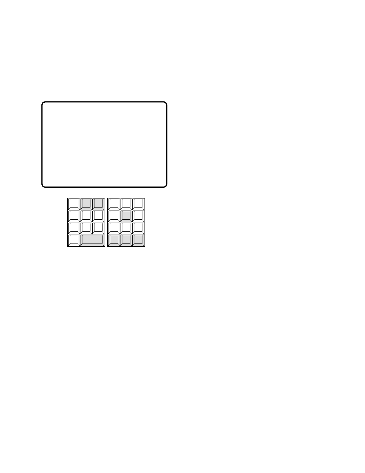
94
■ Video Loss History Table
There are 100 video loss detection records stored in
chronological order in 10 pages of table.
1. Select a monitor for displaying the history.
Refer to the Monitor Selection.
2. Pressing the [5] key while holding down the [MONI-
TOR] key will display the VIDEO LOSS HISTORY table
as shown in the figure on the active monitor.
The columns in the table indicate the states as shown
below.
LCAM: Logical camera number that is connected to
the system.
STATE: Indicates video loss changes.
OK: Video loss is recovered.
LS: Video level is below normal and in sync.
VL: Video level is below normal and out of sync.
HL: Video level is above normal and out of sync.
TYPE: Place where the video loss occurs.
S: MXSW input
C: MXCONT input
DATE-TIME: Date and time when the video loss state
changes.
3. Press the [NEXT] key to select the next page of the history, and press the [PREV] key to back up to the previous page.
4. Press the [NEXT] key while holding down the [SHIFT]
key to select the first page of the history, and press the
[PREV] key while holding down the [SHIFT] key to
select the last page.
5. Pressing the [0] key while holding down the [MONI-
TOR] key will toggle the background camera images
and black on the active monitor.
6. To exit as it stands, select a new monitor.
7. To exit from the mode, press the [CLEAR (ESC)] key
while holding down the [MONITOR] key or select a
camera to be displayed on the active monitor.
VIDEO LOSS HISTORY PG 1
LCAM STATE TYPE DATE-TIME
2 OK S 03/21/00 10:17
2 LS S 03/21/00 10:16
2 OK S 03/21/00 10:15
1 OK C 03/21/00 10:14
3 OK C 03/21/00 10:14
5 VL C 03/21/00 10:12
1 VL C 03/21/00 10:12
3 VL C 03/21/00 10:11
5 VL S 03/21/00 10:10
1 OK C 03/21/00 9:50
CAM ID
VLD S
T&D
ALM S
GEN
SYS S
(
ALARM
)
0
87
MSTA TUS
VLD H
ALL
ALM H
BLK
5964
231
SHIFT
CLEAR
(
ESC
)
EXIT
GROUP
PRESET
PREV
S-CTL IDOPE ID
NEXT
GROUP
SEQ
PAUSE STOP
TOUR
SEQ
REV
RUN
FWD
RUN
OSD
VER
MONITOR
LOCK
OSD SERVICE
Page 91
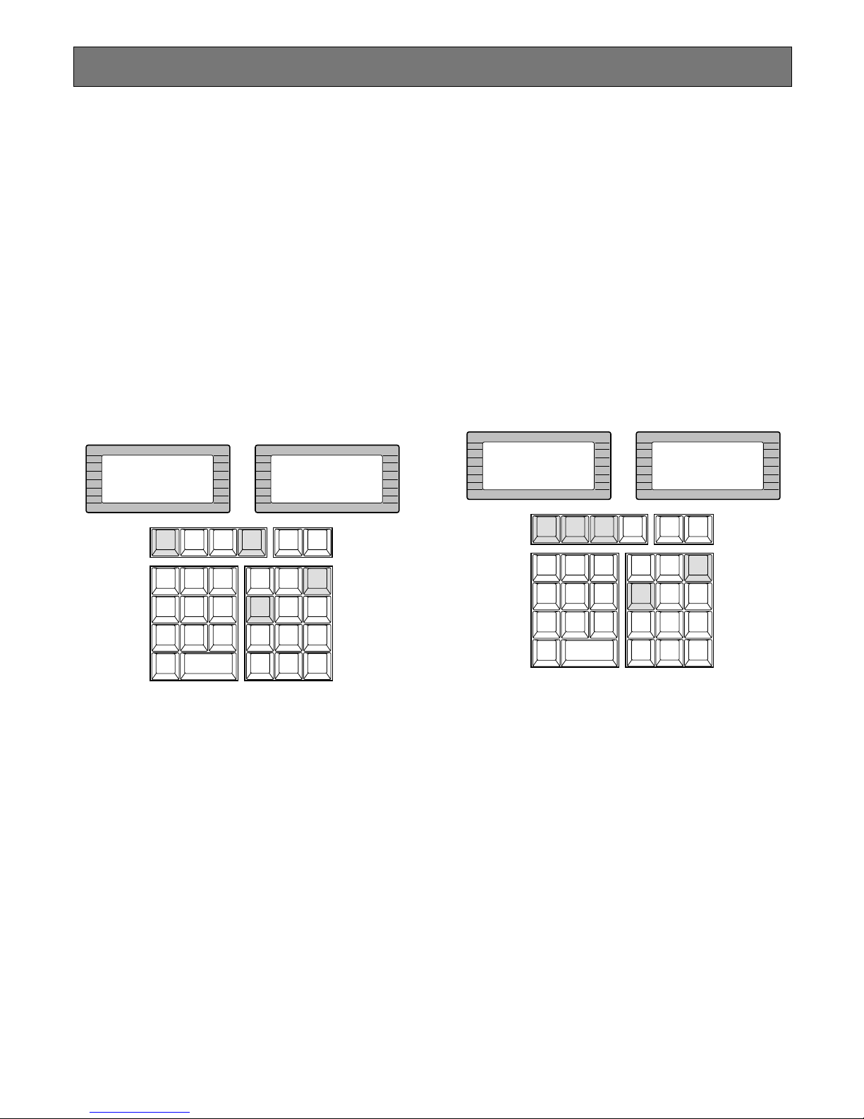
95
Alarm Control
When cameras and monitor are armed for alarm response
with an alarm input, the camera pictures associated with
that alarm input is displayed on the monitor when the alarm
is received.
When an alarm is received, the ALARM indicator lights. The
indicator remains lit until all alarms are cleared by pressing
the RESET key.
■ Alarm Arming Control
1. Select an alarm number by pressing the numeric keys,
followed by the [ALARM] key.
2. Pressing the [ARM] key repeatedly will arm or disarm
cameras and monitor for alarm response with the
selected alarm.
“Armed” or “Disarmed” will be displayed on the LCD
display.
3. Pressing the [NEXT] key while holding down the
[ALARM] key will select the next higher alarm number,
or pressing the [PREV] key while holding down the
[ALARM] key will select the next lower alarm number.
4. Pressing the [ARM] key repeatedly will arm or disarm
cameras and monitor for alarm response with the
selected alarm.
5. To exit from alarm selecting mode, press the [CLEAR
(ESC)] key.
■ To Cancel Alarms
1. Select an activated alarm number that is displayed on
the active monitor by pressing the numeric keys, followed by the [ALARM] key.
2. Select the alarm action number by pressing the numeric key, then press the [ACK] key to acknowledge the
activated alarm manually.
The acknowledged alarm picture is displayed on the
active monitor, and the ACK indicator on the controller
is turned on.
Note: By the factory default setting, pressing only the
[ACK] key will interpret it as the alarm action #0.
3. After acknowledging the alarm, press the [RESET] key
to reset the alarm.
The ACK indicator will go off.
Note: All reset function is available without selecting
the activated alarms. Pressing the [RESET] key
while holding down the [SHIFT] key will cancel all
currently activated alarms at once.
INFORMATION
Entry:43
INFORMATION
Alarm 43
Armed
ALARM
ACK
RESET
ALL
RESET
ARM
F.1 F.2
CAM ID
VLD S
T&D
ALM S
GEN
SYS S
(
ALARM
)
0
87
MSTA TUS
VLD H
ALL
ALM H
BLK
5964
231
SHIFT
CLEAR
(
ESC
)
EXIT
GROUP
PRESET
PREV
S-CTL IDOPE ID
NEXT
GROUP
SEQ
PAUSE STOP
TOUR
SEQ
REV
RUN
FWD
RUN
OSD
VER
MONITOR
LOCK
OSD SERVICE
INFORMATION
Alarm 43
INFORMATION
Alarm 43
Acknowledged
ALARM
ACK
RESET
ALL
RESET
ARM
F.1 F.2
CAM ID
VLD S
T&D
ALM S
GEN
SYS S
(
ALARM
)
0
87
MSTA TUS
VLD H
ALL
ALM H
BLK
5964
231
SHIFT
CLEAR
(
ESC
)
EXIT
GROUP
PRESET
PREV
S-CTL IDOPE ID
NEXT
GROUP
SEQ
PAUSE STOP
TOUR
SEQ
REV
RUN
FWD
RUN
OSD
VER
MONITOR
LOCK
OSD SERVICE
Page 92
An example of an alarm input and the resulting alarm activation is given below.
[Basic setup]
• Alarm Input #1 is to activate the Group Sequence (GSeq #1) as alarm action #0. The Group Sequence has
priority 12.
• The monitors assigned to run the sequence are monitors #1, #2, #3 and #4.
• The target monitor is monitor #5. It displays the images
in hold mode.
• Monitor #5 displays the images of camera #5 in spot
mode.
[Operations]
1. Alarm #1 is activated.
2. Monitor #5 displays the alarm indication "ALMA1-0" to
indicate that alarm #1 is activated (Fig.).
3. The Group sequence (G-Seq #1) runs on monitors #1,
#2, #3 and #4 with the lowest priority (Fig.).
4. Reset alarm #1 by selecting it and pressing the
[ALARM] key followed by the [RESET] key.
This will turn off the alarm indication on monitor #5. The
sequence (G-Seq #1) continues running on the monitors.
5. To stop the sequence on the monitors, select one of the
monitors by pressing the [MONITOR] key, then press
the [STOP] key.
M1 G1 R
Group Sequence Monitors Target Monitor
M2 G1 R
M3 G1 R M4 G1 R M5 ALMA1-0
96
Page 93
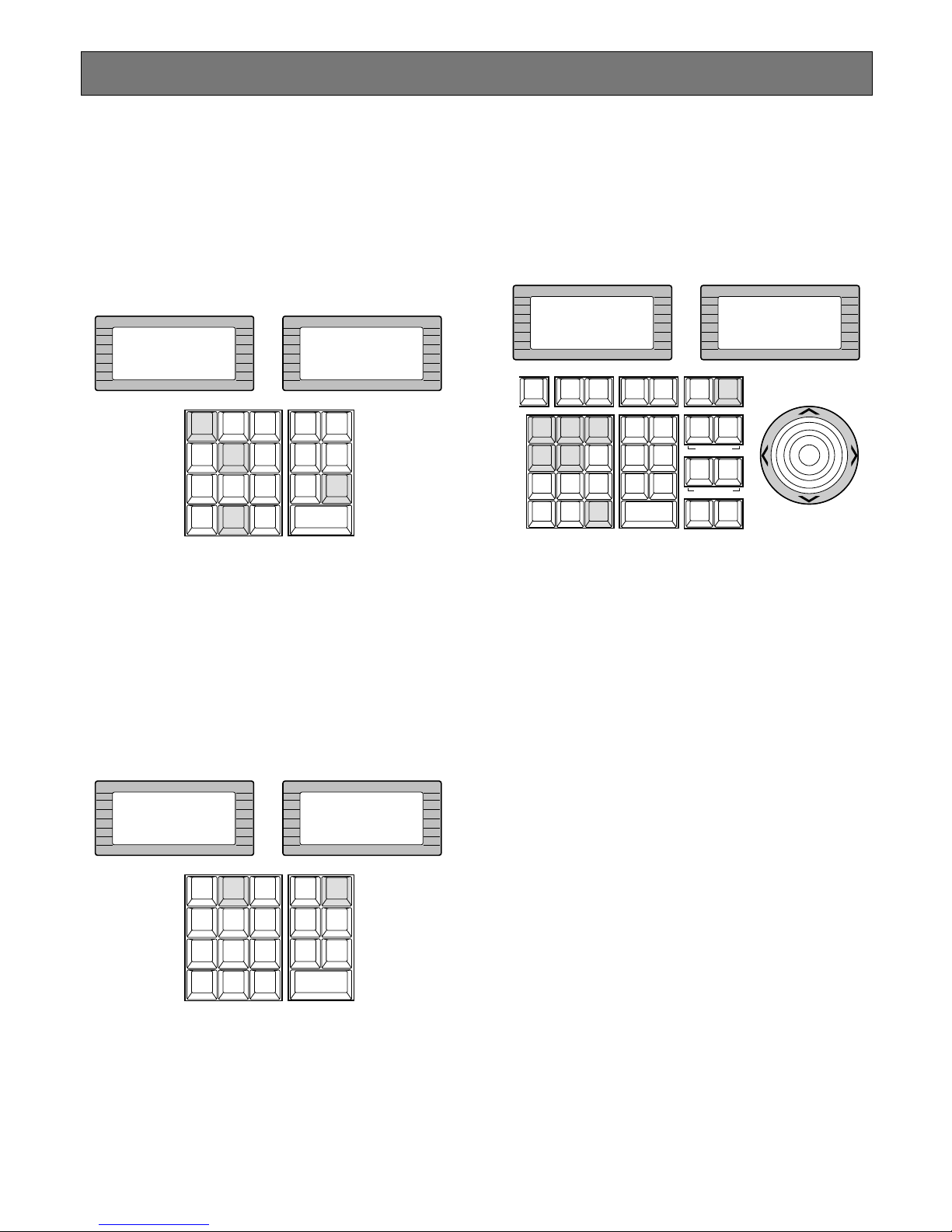
97
Other Functions
■ Digital Output Function
The following function is available only if Digital Outputs has
been previously established through the Administration
Console.
1. Select a Digital Output number by pressing the numeric keys.
2. Press the [DIGITAL OUT] key to produce a one shot
pulse for activating an assigned event.
■ Area Control Function
The following function is available only if the monitors are
previously assigned to the areas through the Administration
Console.
1. Select an Area number by pressing the numeric keys.
2. Press the [AREA] key to apply all the controller’s functions to the selected area.
Note: Pressing the [AREA] key with no numeric input
will display currently selected area number on the
LCD display.
■ Joystick Calibration
The following procedure is available at startup after the
“HELLO!” display on the LCD display of the controller or
after logging out.
1. Select [1][2][3][4][5] by pressing the numeric keys,
then press the [F6] key.
2. Move the Joystick to the position specified by the LCD
display prompts and hold it, then press the [CLEAR]
key.
Repeat this procedure.
The prompts on the LCD display will be replaced by
pressing the [CLEAR] key as shown below.
Center (Press CLR)
↓
Up (Press CLR)
↓
Right (Press CLR)
↓
Down (Press CLR)
↓
Left (Press CLR)
INFORMATION
Entry:105
INFORMATION
DigOut105
LOGOUT
AUX1 OFF AUX1 ON
CALL
PRESET
PGM
PRESET
CAM
POSI
DIGITAL
OUT
DEF OFF DEF ON
AREA
AUX2 OFF AUX2 ON
CAMERA
(ENTER)
AUTO PAN
CAM ID
VLD S
T&D
ALM S
GEN
SYS S
(
ALARM
)
0
87
MSTA TUS
VLD H
ALL
ALM H
BLK
5964
231
SHIFT
CLEAR
(
ESC
)
EXIT
INFORMATION
Entry:2
INFORMATION
Area 2
LOGOUT
AUX1 OFF AUX1 ON
CALL
PRESET
PGM
PRESET
CAM
POSI
DIGITAL
OUT
DEF OFF DEF ON
AREA
AUX2 OFF AUX2 ON
CAMERA
(ENTER)
AUTO PAN
CAM ID
VLD S
T&D
ALM S
GEN
SYS S
(
ALARM
)
0
87
MSTA TUS
VLD H
ALL
ALM H
BLK
5964
231
SHIFT
CLEAR
(
ESC
)
EXIT
INFORMATION
ID:
NO OPERATOR
INFORMATION
ID:12345
UP
DOWN
R
L
ARM
F.1 F. 2 F.3
CMENU
OFF
F.4
CMENU
ON
F.5 F. 6
CLOSE
IRIS
WIPER
OPEN
NEAR FA R
WIDE TELE
AUTO FOCUS
ZOOM
LOGOUT
AUX1 OFF AUX1 ON
CALL
PRESET
PGM
PRESET
CAM
POSI
DIGITAL
OUT
CAM ID
VLD S
T&D
ALM S
GEN
SYS S
(
ALARM
)
0
87
DEF OFF DEF ON
MSTA TUS
VLD H
ALL
ALM H
BLK
5964
231
SHIFT
CLEAR
(
ESC
)
EXIT
AREA
AUX2 OFF AUX2 ON
DEFAULT
FOCUS
CAM
FUNC
CAMERA
(ENTER)
AUTO PAN
Page 94
99
OPERATING PROCEDURES
(when a WV-CU350 is connected)
Page 95
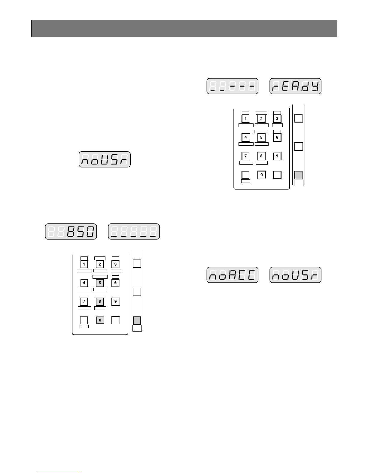
100
Before starting the following procedures, all system components must be turned on.
The following procedures apply when the WV-CU350
System Controller is connected to the system.
■ Log-in
1. Turn on the power switches of all system components.
2. Turn on the power of the WV-CU350 System Controller
by connecting the AC adapter to the AC outlet.
The LINK indicator lights up and “NO USER” will
appear on the LED display of the system controller.
3. Select your registered operator ID number (up to 5 digits) by pressing the numeric buttons, then press the
[CAMERA (ENTER)] button.
The underline display now appears on the LED display
of the controller.
4. Select your registered Password (up to 5 digits) by
pressing the numeric buttons, then press the [CAM-
ERA (ENTER)] button.
If operator ID and password are correct, “READY” will
appear on the LED display.
Note: If an operator ID and password error have
occurred, the PROHIBITED indicator on the controller will light up and “NO ACCESS” will blink on
the LED display for about 3 seconds. Then the
Log-in procedure automatically returns to the start.
Log-in and Log-out
PROGRAM
PRESET
CALL
PRESET
AUX1 OFF
ALM S
CAM IDT&D
AUX1 ON
VLD S
GEN
WIPER
SYS S
AUX2 OFF
ALM H
AUX2 ON
VDL H
ALL
SHIFT BLK EXIT
CLEAR
(
ESC
)
DEF OFF DEF ON
CAMERA
(
ENTER
)
AUTO
PAN
MON STATUS
PROGRAM
PRESET
CALL
PRESET
AUX1 OFF
ALM S
CAM IDT&D
AUX1 ON
VLD S
GEN
WIPER
SYS S
AUX2 OFF
ALM H
AUX2 ON
VDL H
ALL
SHIFT BLK EXIT
CLEAR
(
ESC
)
DEF OFF DEF ON
CAMERA
(
ENTER
)
AUTO
PAN
MON STATUS
Page 96
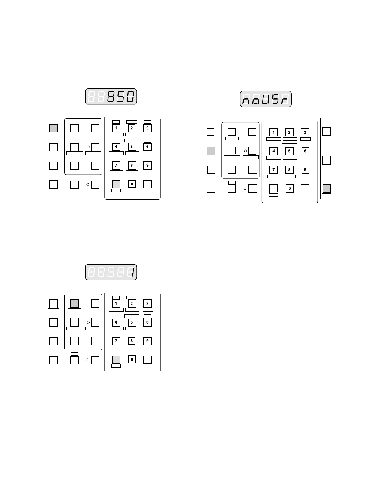
101
■ IDs Display Function
This controller has the following functions.
● Operator ID Display
Pressing the [GROUP PRESET] button while holding
down the [SHIFT] button will display the Operator ID on
the LED display.
● Controller ID Display
Pressing the [PREV] button while holding down the
[SHIFT] button will display the Controller ID on the LED
display.
■ Log-out
This function is used when an operator is leaving the controller, or no longer requires access to the system.
1. Hold down the [LOGOUT] button and then press the
[CAMERA (ENTER)] button to log out.
“NO USER” is displayed on the LED display of the controller.
AUX1 OFF
ALM S
CAM IDT&D
AUX1 ON
VLD S
NEXTPREV
S-CTL ID
STOPPAUSE
CAM MENU ONCAM MENU OFF
TOUR
SEQ
GROUP
SEQ
MONITOR
LOCK
OSD SERVICE
CAM FUNC
OSD
OPE ID
GROUP PRESET
LOG OUT
F1
F2
GEN
WIPER
SYS S
AUX2 OFF
ALM H
MON STATUS
AUX2 ON
VDL H
ALL
SHIFT BLK EXIT
CLEAR
(
ESC
)
DEF OFF DEF ON
AUX1 OFF
ALM S
CAM IDT&D
AUX1 ON
VLD S
NEXTPREV
S-CTL ID
STOPPAUSE
CAM MENU ONCAM MENU OFF
TOUR
SEQ
GROUP
SEQ
MONITOR
LOCK
OSD SERVICE
CAM FUNC
OSD
OPE ID
GROUP PRESET
LOG OUT
F1
F2
GEN
WIPER
SYS S
AUX2 OFF
ALM H
MON STATUS
AUX2 ON
VDL H
ALL
SHIFT BLK EXIT
CLEAR
(
ESC
)
DEF OFF DEF ON
PROGRAM
PRESET
CALL
PRESET
AUX1 OFF
ALM S
CAM IDT&D
AUX1 ON
VLD S
GEN
WIPER
SYS S
AUX2 OFF
ALM H
AUX2 ON
VDL H
ALL
SHIFT BLK EXIT
CLEAR
(
ESC
)
DEF OFF DEF ON
CAMERA
(
ENTER
)
AUTO
PAN
MON STATUS
NEXTPREV
S-CTL ID
STOPPAUSE
CAM MENU ONCAM MENU OFF
TOUR
SEQ
GROUP
SEQ
MONITOR
LOCK
OSD SERVICE
CAM FUNC
OSD
OPE ID
GROUP PRESET
LOG OUT
F1
F2
Page 97
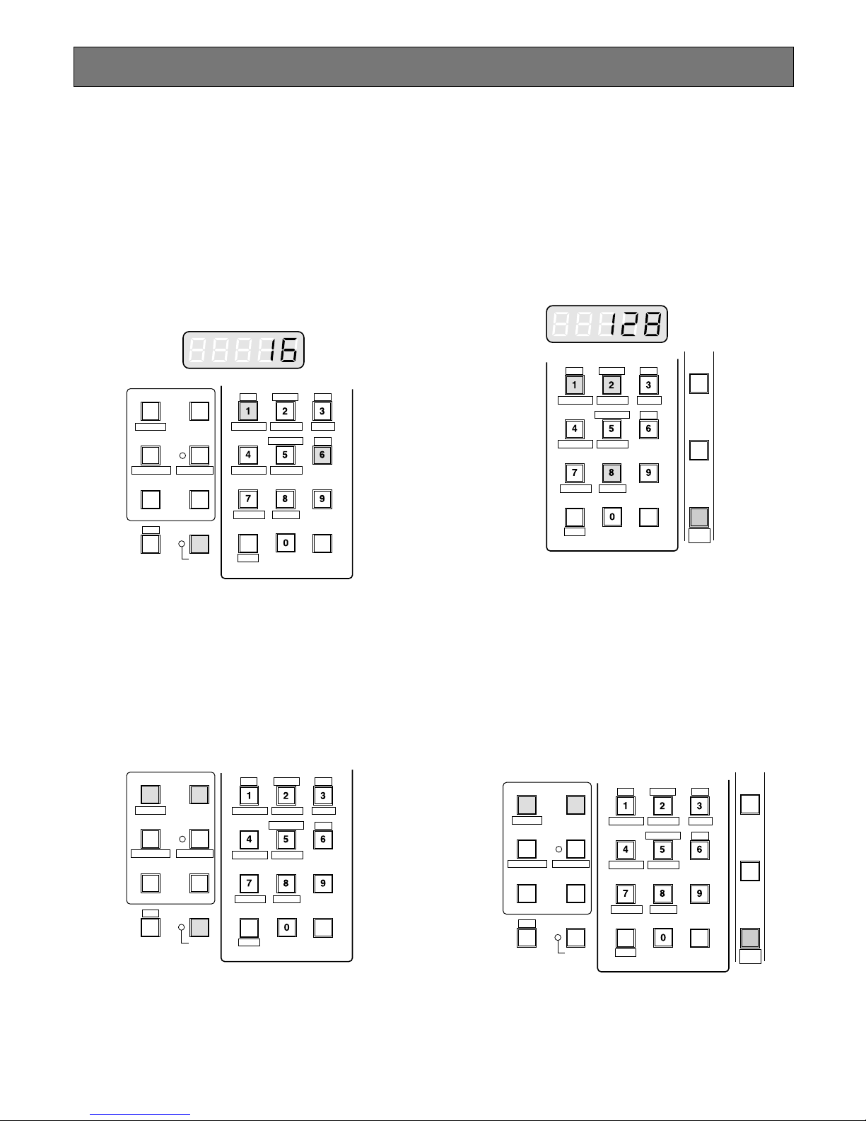
102
Monitor and Camera Selection
After log-in, the following operations are available for controlling the system.
The operation begins with selecting a monitor; then select a
camera to be displayed on the active monitor screen.
■ Monitor Selection
1. Select the desired monitor number by pressing the
numeric buttons, then press the [MONITOR] button to
execute the selection.
The MONITOR indicator on the controller is turned on
and the selected monitor number is now displayed on
the LED display of the controller.
If the selected monitor number is not valid or partitioned, the PROHIBITED indicator is on and the number
on the LED display will blink for about 3 seconds.
Return to step 1 and select a new monitor number.
2. Pressing the [NEXT] button while holding down the
[MONITOR] button will select the next higher monitor
number, or pressing the [PREV] button while holding
down the [MONITOR] button will select the next lower
monitor number.
Note: The BUSY indicator lights, if the monitor is select-
ed by a higher priority operator. Control of the
same monitor is denied to an operator with a lower
priority.
■ Camera Selection
1. Select the desired monitor.
Refer to the Monitor Selection.
2. Select the desired camera number by pressing the
numeric buttons, then press the [CAMERA (ENTER)]
button.
The selected camera picture appears on the currently
selected monitor and the selected camera number is
now displayed on the LED display of the controller.
If the selected camera number is not valid or partitioned, the PROHIBITED indicator is on and the number
on the LED display will blink for about 3 seconds.
Return to step 2 and select a new camera number.
3. Pressing the [NEXT] button while holding down the
[CAMERA (ENTER)] button will replace the currently
selected camera with the next higher camera number,
or pressing the [PREV] button while holding down the
[CAMERA (ENTER)] button will replace the currently
selected camera with the next lower camera number.
Note: The BUSY indicator lights, if the camera is
selected by a higher priority operator. Control of
the same camera is denied to an operator with a
lower priority.
AUX1 OFF
ALM S
CAM IDT&D
AUX1 ON
VLD S
GEN
WIPER
SYS S
AUX2 OFF
ALM H
AUX2 ON
VDL H
ALL
SHIFT BLK EXIT
CLEAR
(
ESC
)
DEF OFF DEF ON
MON STATUS
NEXTPREV
S-CTL ID
STOPPAUSE
CAM MENU ONCAM MENU OFF
TOUR
SEQ
GROUP
SEQ
MONITOR
LOCK
OSD SERVICE
OSD
AUX1 OFF
ALM S
CAM IDT&D
AUX1 ON
VLD S
NEXTPREV
S-CTL ID
STOPPAUSE
CAM MENU ONCAM MENU OFF
TOUR
SEQ
GROUP
SEQ
MONITOR
LOCK
OSD SERVICE
OSD
GEN
WIPER
SYS S
AUX2 OFF
ALM H
MON STATUS
AUX2 ON
VDL H
ALL
SHIFT BLK EXIT
CLEAR
(
ESC
)
DEF OFF DEF ON
PROGRAM
PRESET
CALL
PRESET
AUX1 OFF
ALM S
CAM IDT&D
AUX1 ON
VLD S
GEN
WIPER
SYS S
AUX2 OFF
ALM H
AUX2 ON
VDL H
ALL
SHIFT BLK EXIT
CLEAR
(
ESC
)
DEF OFF DEF ON
CAMERA
(
ENTER
)
AUTO
PAN
MON STATUS
PROGRAM
PRESET
CALL
PRESET
AUX1 OFF
ALM S
CAM IDT&D
AUX1 ON
VLD S
GEN
WIPER
SYS S
AUX2 OFF
ALM H
AUX2 ON
VDL H
ALL
SHIFT BLK EXIT
CLEAR
(
ESC
)
DEF OFF DEF ON
CAMERA
(
ENTER
)
AUTO
PAN
MON STATUS
NEXTPREV
S-CTL ID
STOPPAUSE
CAM MENU ONCAM MENU OFF
TOUR
SEQ
GROUP
SEQ
MONITOR
LOCK
OSD SERVICE
OSD
Page 98
103
■ Priority Lock
This function is used to retain control of a monitor for an
operator, even after that operator has selected another
monitor.
Caution: This function will prevent operators with a lower
priority from gaining control of a monitor.
However, higher or equal priority operators may still
gain control of that monitor.
● Applying Priority Lock
1. Select the desired monitor to apply Priority Lock.
Refer to the Monitor Selection.
2. Pressing the [MONITOR] button while holding down
the [SHIFT] button will toggle the Priority Lock mode on
and off on the active monitor.
If the Priority Lock mode is selected, the monitor number with “L” sign is displayed on the active monitor and
the MONITOR LOCK indicator on the controller is on.
● Releasing Priority Lock
1. Select the desired monitor to release Priority Lock.
Refer to the Monitor Selection.
2. Pressing the [MONITOR] button while holding down
the [SHIFT] button will release the lock mode.
The monitor number is displayed normally on the active
monitor and the MONITOR LOCK indicator on the controller is now off.
AUX1 OFF
ALM S
CAM IDT&D
AUX1 ON
VLD S
GEN
WIPER
SYS S
AUX2 OFF
ALM H
AUX2 ON
VDL H
ALL
SHIFT BLK EXIT
CLEAR
(
ESC
)
DEF OFF DEF ON
MON STATUS
NEXTPREV
S-CTL ID
STOPPAUSE
CAM MENU ONCAM MENU OFF
TOUR
SEQ
GROUP
SEQ
MONITOR
LOCK
OSD SERVICE
CAM FUNC
OSD
OPE ID
GROUP PRESET
LOG OUT
F1
F2
Page 99
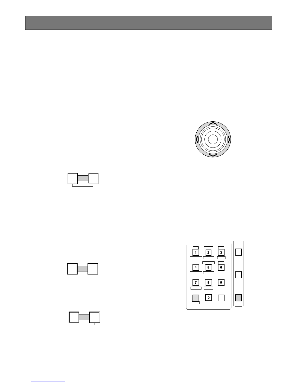
104
Controlling Camera Site Accessories
Controls for camera site accessories are located on the
right side of the front panel of the System Controller.
Included are Zoom Control, Focus Control, Iris Control,
Preset and Pan/Tilt Controls. Normally, combination cameras equipped with the specific feature or a WV-RC100 or
WV-RC150 Receiver are required to utilize these functions.
■ Lens Control
Note: Confirm that the specified lens, with power
zoom/focus functions, is mounted on the camera. Also
confirm that the Lens Selection (DC/VIDEO) on the
camera is set to the DC position.
Function capabilities vary between cameras. Referring
to the operating instructions of each camera is recommended.
1. Select the desired monitor and camera.
Refer to the Monitor Selection and Camera Selection.
2. Press the [FOCUS NEAR/FAR] buttons while observing the monitor to adjust the lens focus to achieve a
sharply focused picture.
By pressing these buttons at the same time, the lens
focus is set automatically, if the specified camera with
the auto focus feature is used.
3. Press the [ZOOM TELE/WIDE] buttons while observing
the monitor to adjust the lens zoom to achieve the
desired picture.
Press the [TELE] button to optically bring an object
closer. Pressing the [WIDE] button has the reverse
effect.
4. Press the [IRIS CLOSE/OPEN] buttons to close/open
the lens iris. Adjust the lens iris by using these buttons
to obtain the proper picture exposure.
By pressing these buttons at the same time, the lens
iris is reset to the factory default setting.
■ Pan/Tilt Control
● Pan/Tilt Control (Manual Operation)
1. Select the desired monitor and camera.
Refer to the Monitor Selection and Camera Selection.
2. Move the Joystick Controller to move the Pan/Tilt Head
towards the desired direction.
If the joystick is positioned in between UP and R, the
Pan/Tilt Head moves diagonally towards Up and Right.
Eight directions are available: Up / Down / Right / Left /
Up-Right / Up-Left / Down-Right / Down-left.
● Pan/Tilt Control (Auto Panning)
The following function requires the use of cameras
equipped with this specific feature.
1. Select the desired monitor and camera.
Refer to the Monitor Selection and Camera Selection.
2. Pressing the [CAMERA (ENTER)] button while holding
down the [SHIFT] button will activate the Auto Panning
function of the selected camera.
3. To cancel the auto panning function, move the Joystick
Controller.
FOCUS
FARNEAR
AUT O FOCUS
ZOOM
TELEWIDE
IRIS
OPENCLOSE
AUT O IRIS
UP
LR
DOWN
PROGRAM
PRESET
CALL
PRESET
AUX1 OFF
ALM S
CAM IDT&D
AUX1 ON
VLD S
GEN
WIPER
SYS S
AUX2 OFF
ALM H
AUX2 ON
VDL H
ALL
SHIFT BLK EXIT
CLEAR
(
ESC
)
DEF OFF DEF ON
CAMERA
(
ENTER
)
AUTO
PAN
MON STATUS
Page 100
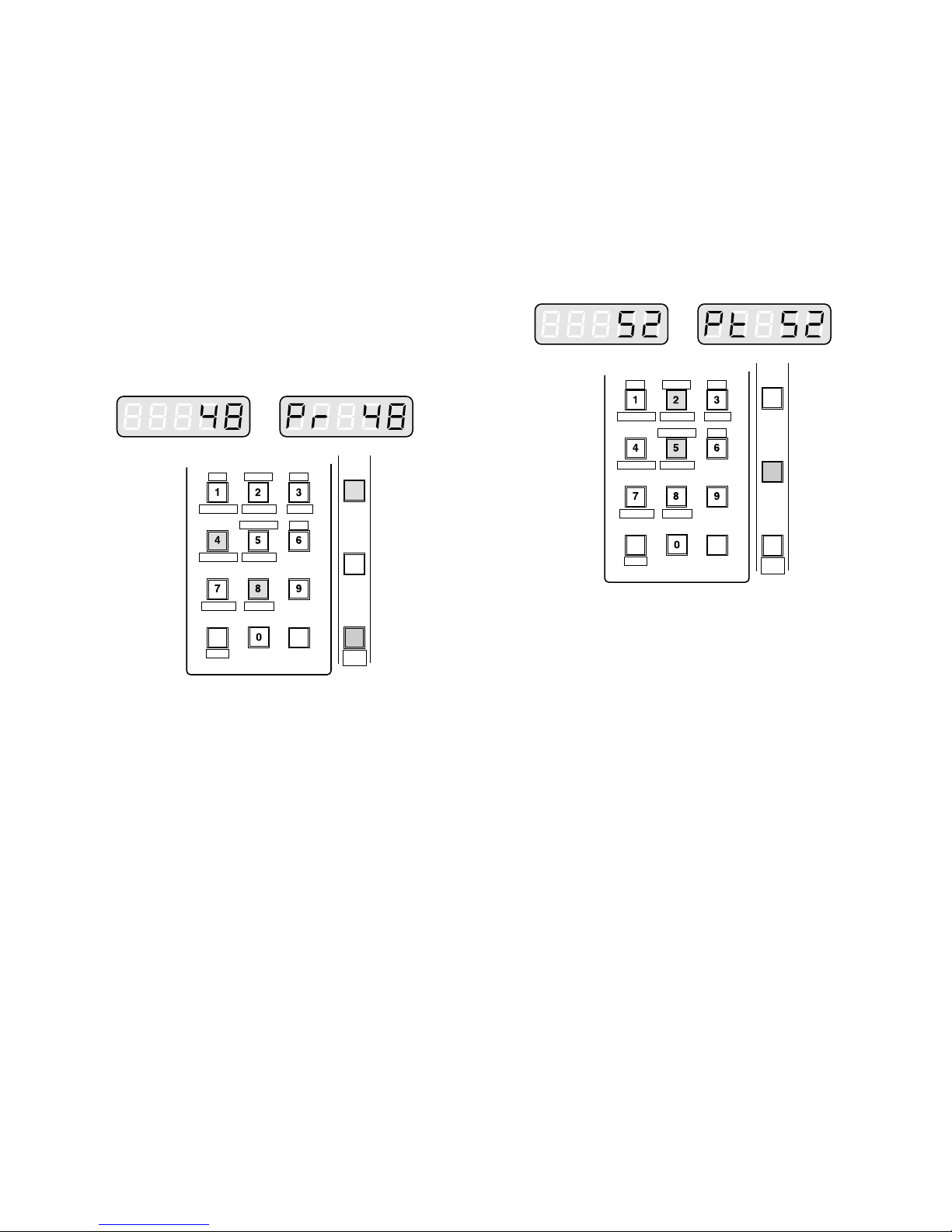
105
● Pan/Tilt Control
(Program Preset Position)
The following function requires the use of cameras
equipped with this specific feature.
1. Select the desired monitor and camera.
Refer to the Monitor Selection and Camera Selection.
2. Move the camera to the position to be preset by moving the Joystick Controller and pressing the lens control
buttons.
3. Select the desired preset position number by pressing
the numeric buttons.
4. Holding down the [PROGRAM PRESET] button, and
then press the [CAMERA (ENTER)] button to save a
preset position of the selected camera.
Note: If the position number entered has been stored
previously, the old position will be overwritten by
the new one.
● Pan/Tilt Control (Call Preset Position)
The following function requires the use of cameras
equipped with this specific feature.
1. Select the desired monitor and camera.
Refer to the Monitor Selection and Camera Selection.
2. Select the preset position number by pressing the
numeric buttons.
3. Press the [CALL PRESET] button to move to the preset position of the selected camera on the active monitor.
Note: To be able to use the above function, the preset
position number must have been set for that camera.
PROGRAM
PRESET
CALL
PRESET
AUX1 OFF
ALM S
CAM IDT&D
AUX1 ON
VLD S
GEN
WIPER
SYS S
AUX2 OFF
ALM H
AUX2 ON
VDL H
ALL
SHIFT BLK EXIT
CLEAR
(
ESC
)
DEF OFF DEF ON
CAMERA
(
ENTER
)
AUTO
PAN
MON STATUS
PROGRAM
PRESET
CALL
PRESET
AUX1 OFF
ALM S
CAM IDT&D
AUX1 ON
VLD S
GEN
WIPER
SYS S
AUX2 OFF
ALM H
AUX2 ON
VDL H
ALL
SHIFT BLK EXIT
CLEAR
(
ESC
)
DEF OFF DEF ON
CAMERA
(
ENTER
)
AUTO
PAN
MON STATUS
 Loading...