

Page 1
DIGITAL ENSEMBLE
SX-PR950
Thank you for purchasing the PR950. The PR950 is operated for the most part in the same way as the PR54, therefore read
the included instructions. This booklet explains assembly, operation and specifications that differ from the PR54, therefore
read it thoroughly.
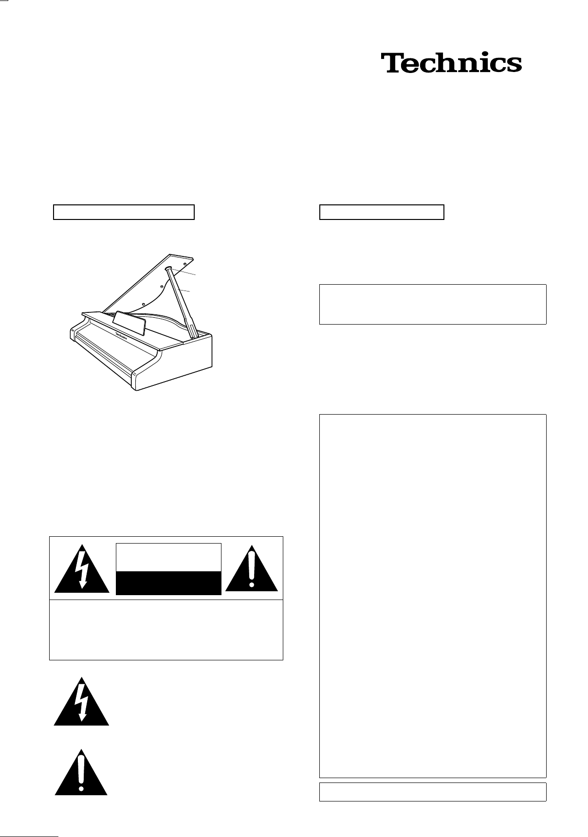
How to open the top cover
You can open the cover and lift the support into an upright
position.
Top cover
Hole
Support
Warning!
● The piano top cover is quite heavy, and when opening it,
be sure to insert the support into the hole to secure the
top cover in the open position . Be careful when cl osing the
top cover not to catch fingers or clothing under the top
cover or in the hinges.
● Children should be advised not to open or close the top
cover, and should not be permitted to operate the piano
without adult supervision.
The following mark and symbols are located on bottom
of the unit.
CAUTION
RISK OF ELECTRIC SHOCK
DO NOT OPEN
CAUTION: TO REDUCE THE RISK OF ELECTRIC
SHOCK, DO NOT REMOVE SCREWS.
NO USER-SERVICEABLE PARTS
INSIDE.
REFER SERVICING TO QUALIFIED
SERVICE PERSONNEL.
The lightning flash with arrowhead symbol,
within an equilateral triangle, is intended to
alert the user to the presence of uninsulate d
“dangerous voltage” within the product’s
enclosure that may be of sufficient magnitude to constitute a risk of electric shock to
persons.
The exclamation point within an equilateral
triangle is intended to alert the user to the
presence of important operating and maintenance (servicing) instructions in the literature accompan ying the applian ce.
Care and maintenance
䡲䡲䡲䡲 Care of the finished surfaces
● To dust the piano, use a feather duster or wipe gently
with a soft cloth.
● To avoid scratching the surface, refrain from applying
too much pressure when dusting the piano.
Never use petroleum-based solvents such as thinner or
benzene, and do not use ch emica lly trea ted dust cloths ,
as these products will damage the finish of your piano.
䡲䡲䡲䡲 Caution for use
● Do not place vinyl products, books with vinyl-treated
covers, plastic erasers, etc., directly on the piano.
● Do not place vases or other containers of liquids on the
piano.
● Please read the safety instructions on page 6 on Operating Instructions.
CAUTION:
This equipment has been tested and found to comply
with the limits for a Class B digital devi ce, pursuant to
Part 15 of the FCC Rules. These limits are designed to
provide reasonable protection against harmful interference in a residential installation. This equipment generates, uses and can radiate ra dio frequency energy and,
if not installed an d used in accor dance with the in structions, may cause harmful interference to radio c ommunications. However, there is no guarantee that
interference will not occur in a particular installation. If
this equipment does cause harm ful interferen ce to radio
or television reception, which can be determined by turning the equipmen t off and on, t he user is enc ouraged t o
try to correct the interferen ce by one or more of the following measures:
Reorient or rel ocate the receiving antenna.
●
Increase the separat ion between the equipment and
●
receiver.
Connect the equip ment into an outlet on a circuit dif-
●
ferent from that to which the receiver is connected.
Consult the dealer or an exp erienc ed radio/TV techni-
●
cian for help.
Any unauthorized changes or modifications to this equipment would void the user’s authority to operate this
device.
This device complies with Part 15 of the FCC Rules.
Operation is subje ct to the following two conditi ons: (1)
This device may no t cause h armful in terferen ce, and ( 2)
this device must accept any interference received,
including interfe rence that may cause undesired operation.
Marking sign is located on bottom of the unit.
Page 2
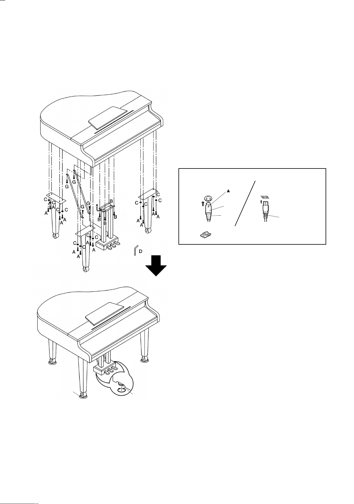
Assembly
Adjuster
Insulator
Follow the steps below to assemble your Technics piano. Make sure you are using the correct parts and that they are in the
correct direction.
● At least 2 people are required for assembly.
● To disassemble the piano, reverse the procedure.
A: Black screws (long)............. 12
B: Black screws (short)..............4
C: Washers..............................12
D: #4 Hexagonal key ................. 1
G: Brass-colored screws............ 4
● Following the assembly, connect the respective cords.
(Piano bottom side)
mark
Plug
Pedal
cord
Use the included clamps to secure the cords.
•
AC INPEDAL IN
Power
cord
● Place the insulators (included) under the casters, positioning
the Technics Piano in the desired location.
● Use the adjus ters to make t he pedal uni t secure.
Caution
If the Technics Piano is to be moved, be sure to first shorten the
adjusters in order to prevent pedal unit damage and scratching
the floor.
䡲䡲䡲䡲 Confirm
After assemb ling, chec k these point s.
● Are any parts left over?
→ Check the assembly procedure again.
● Does the piano rattle when it is rocked?
→ Make sure all the screws are securely tightened.
● Is the power cord firmly inserted?
→ Check again.
● Is the plug of the pedal cord inserted as far into the connector
terminal as it will go?
→ If it is not completely inserted, the sustain and other pedal func-
tions may not work.
● Does the pedal box move when the pedals are pressed?
→ Turn the adjuster to stabilize the pedal box.
2
● When the piano has been moved or transported, retighten the
screws securely.
Page 3

Operations
SOUNDS
RHYTHMS
䡲䡲䡲䡲 The Sostenuto (CENTER) pedal is added.
● About the Sostenuto pedal, refer to page 121 on the Operating Instructions.
● Step 2 of the PEDAL SETTING is different from the PR54.
(page 121 on the Operating Instructions.)
2
. Use the ▲ and ▼ buttons to select pedal, and the ∧ and ∨ buttons to select its function.
䡲䡲䡲䡲 There is no USB terminal. (page 134 on the Operating Instructions.)
● CD-ROM is not included.
● Also, there is no DIGITAL NETWORKING USB demo performance (page 15 on the Operating Instructions.) and COMPUTER
CONNECTION (MIDI) function. (page 134 on the Operating Instructions.)
Specifications
SX-PR950
KEYBOARD 88 KEYS
SOUND GENERATOR PCM
MAX. POLYPHONY 64 NOTES
NUMBER OF SOUNDS 1025 SOUNDS (990 SOUNDS + 2 ORGAN DRAWBARS + 33 DRUM KITS)
PIANO GROUP GRAND, UPRIGHT, ELECTRIC, MODERN
SOUND GROUP STRINGS, VOCAL, GUITAR & HARPSI, BRASS, SAX & WOODWIND,
ORGAN & ACCORDION, SYNTH, BASS, MALLET & ORCH PERC,
WORLD, PIANO MIXTURES, ORCH MIXTURES, DIGITAL DRAWBARS,
DRUM KITS, SOUND EXPLORER
SIMPLE PIANO 嘷
FAVORITES 嘷
PEDAL DAMPER, SOFT*, SOSTENUTO* (*PROGRAMMABLE)
PROGRESSIVE PIANIST 嘷
TOUCH SENSITIVITY 嘷
EFFECT DIGITAL EFFECT, MULTI EFFECT, REVERB, CHORUS, BRILLIANCE
CONDUCTOR RIGHT 1, RIGHT 2, LEFT
TRANSPOSE ±12 NOTES
NUMBER OF RHYTHMS 128 RHYTHMS × 4 VARIATIONS
RHYTHM GROUP POP, ROCK, FUNK & SOUL, DISCO, POP BALLAD, BALLAD,
BALLROOM & SHOW, 8BEAT, 16BEAT, USA, WALTZ & TRAD,
JAZZ & SWING, LATIN & WORLD
METRONOME 嘷
CONTROLS MAIN VOLUME, APC/SEQUENCER VOLUME, BALANCE, MUTE,
START/STOP, INTRO & ENDING 1, INTRO & ENDING 2, FILL IN 1, FILL IN 2,
COUNT INTRO, SYNCHRO & BREAK, TEMPO/PROGRAM, TAP TEMPO,
FADE IN/OUT, SPLIT POINT
AUTO PLAY CHORD MODE: BASIC, ADVANCED 1, ADVANCED 2, PIANIST
MEMORY, ON BASS, CHORD FINDER, LEFT HOLD
3
Page 4

SX-PR950
MUSIC STYLE ARRANGER 嘷
SOUND ARRANGER 嘷
PIANO STYLIST 嘷
ONE TOUCH PLAY 嘷
TECHNI-CHORD 嘷
PANEL MEMORY 3 BANKS × 8
SEQUENCER 16 TRACKS
RESOLUTION: 1/96 PER BEAT
STORAGE CAPACITY: APPROX. 40000 NOTES (10 SONGS MAX.)
INPUT MODES: EASY RECORD, REALTIME RECORD, STEP RECORD
FUNCTIONS: RECORD & EDIT, COPY & PASTE, RANGE EDIT
COMPOSER 8 PARTS: BASS, ACCOMP 1 – 5, DRUMS 1, 2
STORAGE CAPACITY: APPROX. 13000 NOTES
INPUT MODES: REALTIME RECORD, STEP RECORD
FUNCTIONS: EASY COMPOSER, PATTERN COPY,
SEQ TO COMPOSER COPY, LOAD SINGLE COMPOSER
MEMORY: 3 BANKS
DISK 3.5 inch DISK DRIVE for 2HD (1.44MB), 2DD (720KB)
LOAD, SAVE, DIRECT PLAY, SONG MEDLEY, DISK TOOLS,
PREFERENCES
SOUND PART SETTING, MIXER, MASTAR TUNING, KEY SCALING,
APC REVERB SETTING, TECHNI-CHORD, SOUND LOAD OPTION,
SOUND ARRANGER
REVERB & EFFECT MIC REVERB & EFFECT, TONE CONTROL, REVERB, CHORUS, MULTI,
SOUND LOAD OPTION, MIXER
CUSTOMIZE DISPLAY TIMEOUT, DATA PROTECTION, FAVORITES SETTING,
MIDI SETTING LOAD OPTION, LANGUAGE SETTING, DISK PREFERENCES
CONTROL INITIAL, PEDAL SETTING, PANEL MEMORY MODE,
MUSIC STYLE ARRANGER MODE, FADE IN/OUT SETTING
SOUND EDIT EASY EDIT, TONE, PITCH, FILTER, AMPLITUDE, LFO, EFFECT, CONTROLLER
MEMORY: 40, 1 USER DRUM KIT
MIDI PART SETTING, CONTROL MESSAGES, REALTIME MESSAGES,
COMMON SETTING, INPUT/OUTPUT SETTING, MIDI PRESETS, MODE SETTING
DISPLAY LCD: PAGE, CONTRAST, EXIT, DISPLAY HOLD, OTHER PARTS/TR
HELP 嘷
DEMO 嘷
TERMINALS PHONES × 2, LINE OUT (R/MONO,L), AUX IN (R/MONO,L)
MIDI (IN, OUT), PEDAL IN, MIC (VOLUME)
OUTPUT 80 W (40 W × 2)
SPEAKERS 14 cm × 2, 6.5 cm × 2
POWER REQUIREMENT 110 W
AC120V 60 Hz (NORTH AMERICA AND MEXICO)
DIMENSIONS (W × H × D) 141cm × 150 cm × 97 cm (55-1/2" × 59-1/16" × 38-3/16")
NET WEIGHT 98 kg (216.1 lbs)
ACCESSORIES AC CORD, INSULATOR × 3, CLOTH, POLISH
● Design and specifications are subject to change without notice.
QQCG0448A
Se0703S0
4
 Loading...