

Panasonic SL SW967VP Service Manual
A
y
A
A
o
A
A
L
Order No.AD0503036CE
Portable CD Player
SL-SW967VP
SL-SW967VPC
Colour
(A)..........Blue Type (SL-SW967VP only)
(S)..........Silver Type
A6
Specification
CD SECTION
nCD-D
Sampling frequency: 44.1 kHz
No. ofchannels: 2 (left and right, stereo)
Headphone outputlevel: RMS max.8mW+8mW/16Ω
(adjustable)
Frequencyresponse: 20 to 20,000 Hz
(+0.5dB ~ -7dB)
nMP3
Supported bit-rates
(Supports variable bit rates):
Supported sampling frequency: 48kHz/44.1kHz/32kHz
Maximum number or items
(total no. of albums and tracks):
Maximum album levels: 100
nPickup
Lightsource: Semiconductor laser
Wavelength: 780 nm
RADIOSECTION
nFrequenc
Radio frequency: FM; 87.90—107.90 MHz
(128kbps is recommended)
32kbps to 320kbps
999
(0.2 MHz steps)
87.50—108.00 MHz
(0.1 MHz/0.05 MHz steps)
M; 520—1710 kHz
(10 kHz steps)
522—1629 kHz
(9 kHz steps)
IF: FM; 10.7 MHz
M; 450kHz
nAudi
Selectivity: FM; 42 dB
M;7.4kHz(6dB)21dB/9kHz
Sensitivity: FM; 7 µV/0.5 mW output
(S/N30 dB)
M; 707 µV/m/0.5 mW output
(MAX)
GENERA
Power supply:
DC input (RP-AC46, not included); DC 4.5V
Operational temperature range: 0°C—40°C(32°F—104 °F)
Rechargeable temperature range: 5°C—40°C(41°F—104 °F)
Playtime:
Using on a flat stable surface at 25°C (77°F), EQ is off, Hold is on,
Anti-skip is on POS 1 (CD-DA), recommended bit rate (MP3: 128
kbps), and the Digital Re-master is off (MP3).Playtime are in hours
and approximat e.
© 2005 Matsushita Electric Industrial Co., Ltd. All
rights reserved. Unauthorized copying and
distribution is a violation of law.
A
SL-SW967VP / SL-SW96 7VPC
Batteries used:
2 alkaline batteries; MP3 disc....100h
CD-DA disc....52h
RADIO (FM BAND)....75h
2 optional rechargeable batteries; MP3 disc....42h
CD-DA disc....22h
RADIO (FM BAND)....30h
Recharging time:
· The playtime maybe less depending on the operating conditions.
· Play time will be considerab ly reduced when playing CD-RW.
Dimensions (WxHxD): 140.0x32.7x141.0mm
bout 3.5 to 4.5 hours
17
(5
/32”×15/16”×59/16”)
Mass: 303g (10.7 oz.) (with batteries)
256g (9.0 oz.) (without batteries)
Note:
Specifications are subject to change without notice.
Mss and dimensions are approximate.
Note on CD-R and CD-RW:
For CD-DA format, use a music disc and finalize*it after recording.
The unit may not be able to play some discs due to the condition of
therecording.
*A process performed after recording that enables CD-R/CD-RW
players to playaudio CD-R and CD-RW.
CONTENTS
Page Page
1 Accessories
2 Precaution of Laser Diode
3 Handling Precautions for Traverse Deck
3.1. Handling of traverse deck (optical pick-up)
3.2. Caution when replacing traverse deck
3.3. Grounding for electrostatic breakdown prevention
4 Operation Checks and Component Replacement Procedures
4.1. Checking for the P.C.B. ass 馳
4.2. Replacement for the lock plate, buckle ornament L and
buckle ornament R
4.3. Replacement for the LCD, button A, button B, buttonC and
LCD ornament
4.4. Replacement for the cover ornament F, cover ornament L,
cover ornament R and buckle
4.5. Replacement for the traverse motor
4.6. Replacement for the optical pick-up
4.7. Replacement for the rest switch
5 Checking the Operation Problems on the Traverse Deck
(Optical Pick-up)
5.1. Check the operations described below on the traverse
deck after replacing
6 Automatic Adjustment Results Display Function (Self-Check
Function)
10
11
12
13
13
14
2
2
4
4
4
4
5
5
8
8
9
6.1. How to display automatic adjustment results
6.2. Display of automatic adjustment results (Self-Check
Function)
7 Display of Self-Diagnostic Function
8 Type Illustration of ICs, Transistors and Diodes
9 Schematic Diagram Notes
9.1. Cautions in Repair exchange of the Diode (D1101, D1102)
10 Schematic Diagram
11 Printed Circuit Board and Wiring connection Diagram
12 Block Diagram
13 Terminal Function of ICs
13.1. IC301(C2BBGF000593): System Control
13.2. IC501(MN6627962JBA): Servo Amp, Servo
Processor,Digital Signal Processor, Digital Filter & D/A
Converter
13.3. IC1301(C2FBEB000007): System Control / LCD Drive
14 Measurements and Adjustments
14.1. Tuner section
15 Replaceme nt Parts List
16 Cabinet Parts Location
17 Traverse Unit Parts Location
18 Packaging
14
14
15
15
16
16
17
23
25
27
27
27
28
30
30
31
35
36
37
1 Accessories
· 1 Pair of stereo headphones: L0BAD0000174
· 1 Hand strap: RGQT0006-K1
2 Precaution of Laser Diode
Caution:
This product utilizes a class 1 laser. Invisible laser radiation is emitted from the optical pick-up lens when the unit is turned on:
1. Do not look directly into the pick-up lens.
2

SL-SW967VP / SL-SW96 7VPC
2. Do not use optical instruments to look at the pick-up lens.
3. Do not adjust the preset variable resister on the optical pick-up.
4. Do not disassemble the optical pick-up unit.
5. If the optical pick-up is replaced, use the manufacture’s specified replacement pick-up only.
6. Use of control or adjustments or performance of procedures other than those specified herein may result in hazardous
radiation exposure.
3
SL-SW967VP / SL-SW96 7VPC
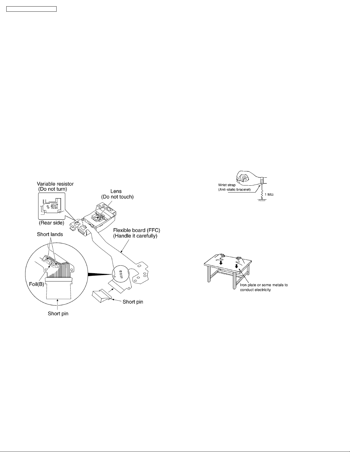
3 Handling Precautions for Traverse Deck
The laser diode in the traverse deck (optical pick-up) may break
down due to potential difference caused by static electricity of
clothes or human body.
So, be careful of electrostatic breakdown during repair of the
traverse deck (optical pick-up).
3.1. Handling of traverse deck
(optical pick-up)
1. Do not subject the optical pick-up to static electricity as it is
extremely sensitive to electrical shock.
2. To protect the laser diode against electrostatic breakdown,
be sure that the short land of the flexible board (FFC board)
should be short-circuit by solder before pulling out the FFC.
Then inserting a short pin or similar object into the
tipoftheflexible board.
(Refer to Fig. 3-1. )
3. Take care not to apply excessive stress to the flexible board
(FFC board).
4. Do not turn the variable resistor (laser power adjustment). It
has already been adjusted. (Refer to Fig. 3-1. )
3.2. Caution when replacing
traverse deck
The new traverse deck short-circuits by the short pin, the foil
(B) and short lands to protect the laser diode against
electrostatic breakdown. Be sure to replace to new one
following procedures.
1. Remove the short pin from the FFC, and then connect it to
the connector.
2. Cut the foil (B). (Refer to Fig. 3-1. ) (Take care not to make
contact with cutting point each other.)
3. Unsolder the short lands. (Refer to Fig. 3-1. )
3.3. Grounding for electrostatic
breakdown prevention
3.3.1. Human body grounding
Use the anti-static wrist strap to discharge the static electricity
from your body. (Refer to Fig. 3-2. )
Fig. 3-1.
Fig. 3-2.
3.3.2. Work table grounding
Put a conductive material (sheet) or steel sheet on the area
where the traverse deck (optical pick-up) is placed, and ground
the sheet. (Refer to Fig. 3-3. )
Fig. 3-3.
Caution:
The static electricity of your clothes will not be grounded
through the wrist strap.
So take care not to let your clothes touch the traverse deck
(optical pick-up).
4

4 Operation Checks and Component Replacement
Procedures
· This section describes procedures for checking the
operation of the major printed circuit boards and
replacing the main components.
· For reassembly after operation checks or replacement,
reverse the respective procedures. Special reassembly
procedures are described only when required.
4.1. Checking for the P.C.B. ass’y
4.1.1. Checking for the P.C.B. ass’y (A
side)
SL-SW967VP / SL-SW96 7VPC
5
SL-SW967VP / SL-SW96 7VPC
· Check the P.C.B. ass’y (A side) as shown below.
4.1.2. Checking for the P.C.B. ass’y (B
side)
· Follow the (Step 1) - (Step 4) of item 5.1.1.
6
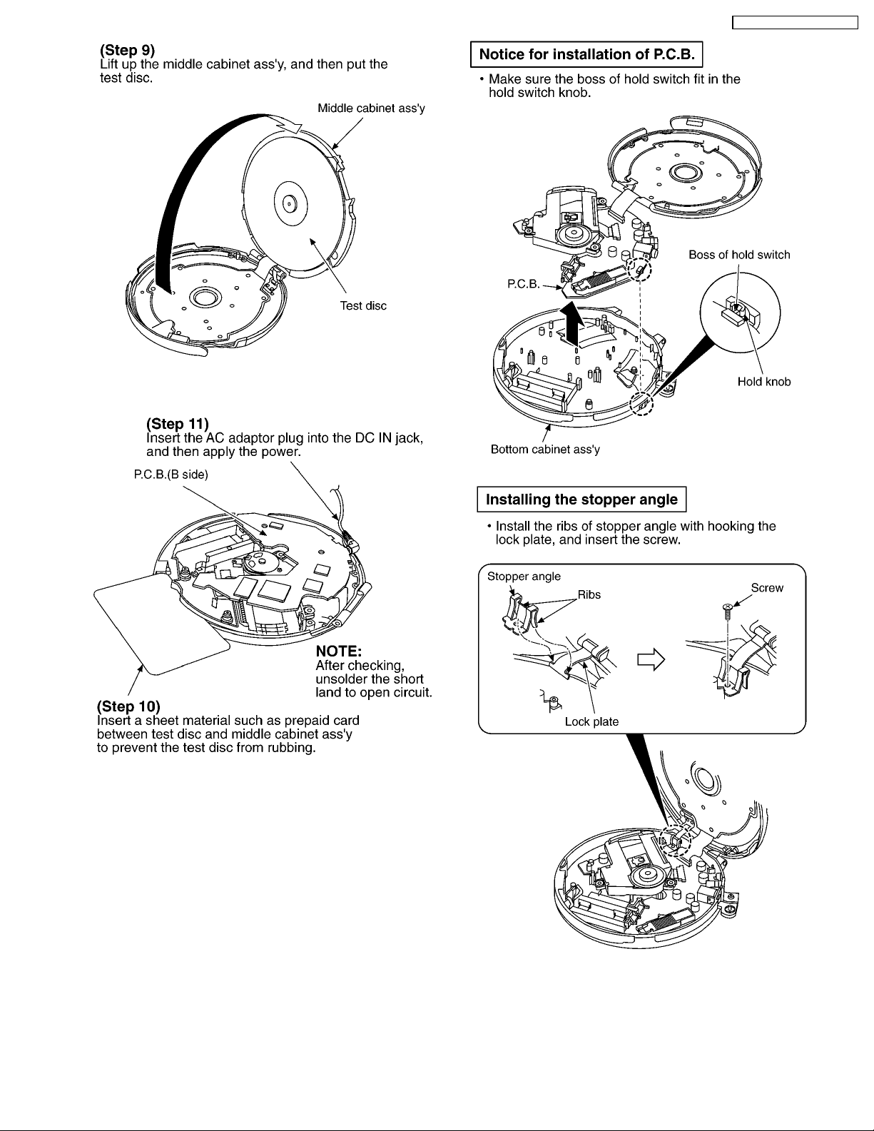
· Check the P.C.B. ass’y (B side) as shown below.
SL-SW967VP / SL-SW96 7VPC
7
SL-SW967VP / SL-SW96 7VPC
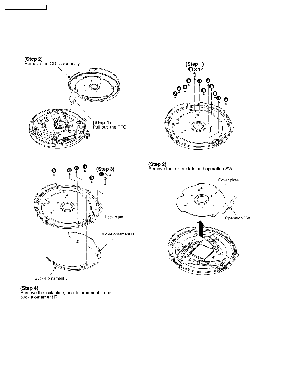
4.2. Replacement for the lock
plate, buckle ornament L and
buckle ornament R
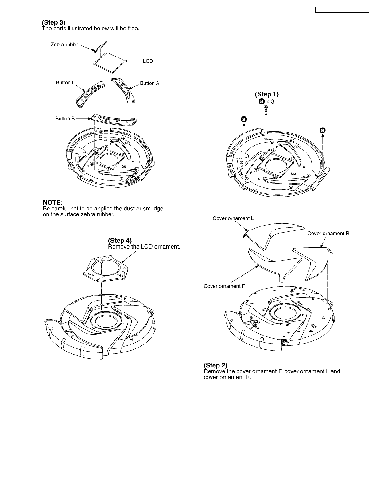
4.3. Replacement for the LCD,
button A, button B, buttonC
and LCD ornament
· Follow the (Step 1) - (Step 3) of item 4.1.1.
· Follow the (Step 1) - (Step 5) of item 4.1.2.
· Follow the (Step 1) - (Step 3) of item 4.1.1.
· Follow the (Step 1) - (Step 5) of item 4.1.2.
· Follow the (Step 1) - (Step 2) of item 4.2.
8
SL-SW967VP / SL-SW96 7VPC
4.4. Replacement for the cover
ornament F, cover ornament L,
cover ornament R and buckle
· Follow the (Step 1) - (Step 3) of item 4.1.1.
· Follow the (Step 1) - (Step 5) of item 4.1.2.
· Follow the (Step 1) - (Step 4) of item 4.2.
· Follow the (Step 1) - (Step 4) of item 4.3.
9

SL-SW967VP / SL-SW96 7VPC
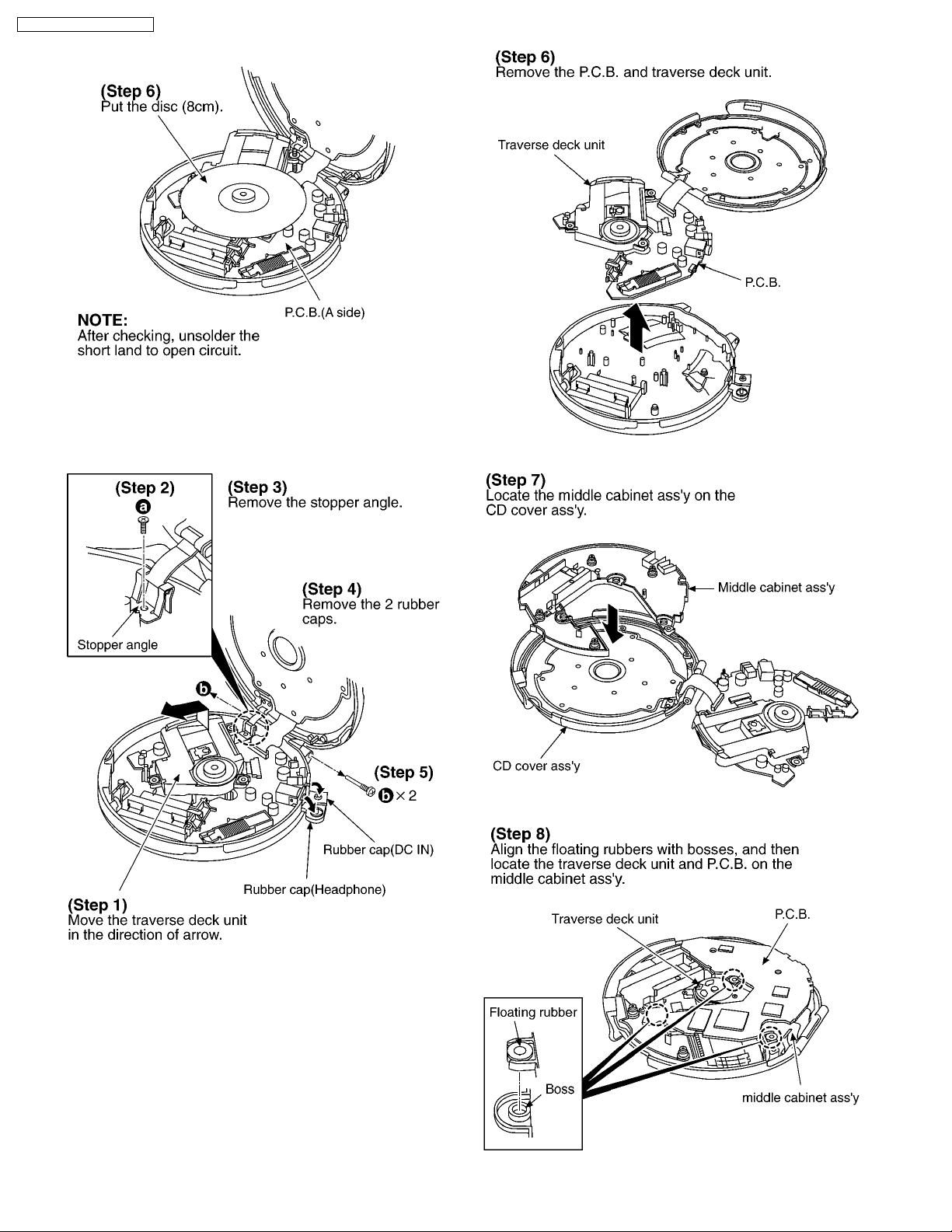
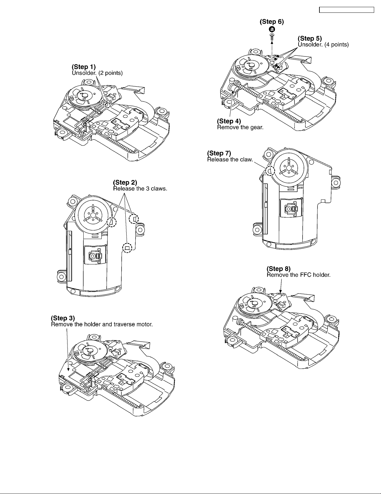
4.5. Replacement for the traverse
motor
· Follow the (Step 1) - (Step 3) of item 4.1.1.
NOTE:
Be sure to confirm the item 3 “Handling Precautions for
Traverse Deck” before removing the traverse deck ass’y.
10
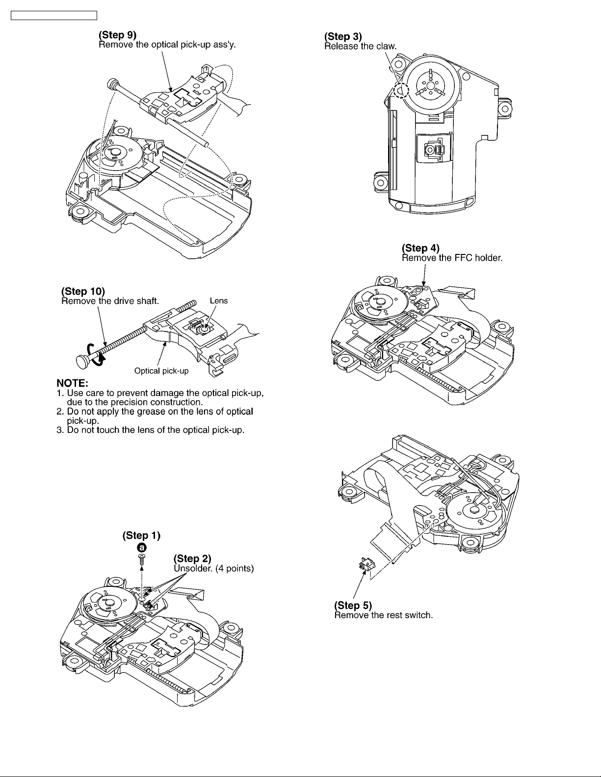
4.6. Replacement for the optical
pick-up
· Follow the (Step 1) - (Step 3) of item 4.1.1.
· Follow the (Step 1) - (Step 3) of item 5.5.
SL-SW967VP / SL-SW96 7VPC
11
SL-SW967VP / SL-SW96 7VPC
4.7. Replacement for the rest
switch
· Follow the (Step 1) - (Step 3) of item 4.1.1.
· Follow the (Step 1) , (Step 2) of item 4.5.
12
 Loading...