

Panasonic SLCT-720-EB, SLCT-720-EG, SLCT-720-EE, SLCT-720-P, SLCT-720-PC Service manual

AD0502011C5
Portable CD Player
SL-CT720P
SL-CT720PC
SL-CT720EB
SL-CT720EE
SL-CT720EG
Colours
(A)...........Blue Type [Except for SL-CT720P]
(S)...........Silver Type [Except for SL-CT720PC]
(D)...........Orange Type [SL-CT720PC only]
A6
© 2005 Matsushita Electric Industrial Co., Ltd. All
rights reserved. Unauthorized copying and
distribution is a violation of law.
SL-CT720P / SL-CT720PC / SL-CT720EB / SL-CT720EE / SL-CT720EG
CONTENTS
Page Page
1 Accessories 3
2 Location of Controls
3 Precaution of Laser Diode
4 Handling Precautions for Traverse Deck
4.1. Handling of traverse deck (optical pick-up)
4.2. Caution when replacing traverse deck
4.3. Grounding for electrostatic breakdown prevention
5 Operation Checks and Component Replacement Procedures
5.1. Checking for the P.C.B.
5.2. Replacement for the CD lid unit, shaft plate, spring A and
spring B
5.3. Replacement for the traverse motor and optical pick-up
5.4. Replacement for the rest switch
5.5. Replacement for the spindle motor
6 Display of Self-Diagnostic Function
7 Checking the Operation Problems on the Traverse Deck
(Optical Pick-up)
7.1. Check the operations described below on the traverse
deck after replacing
8 Automatic Adjustment Results Display Function (Self-Check
Function)
10
10
10
11
11
12
3
4
5
5
5
5
6
6
7
9
8.1. How to display automatic adjustment results
8.2. Display of automatic adjustment results (Self-Check
Function)
9 Type Illustration of ICs, Transistors and Diodes
10 Schematic Diagram Notes
11 Schematic Diagram
12 Printed Circuit Board and Wiring Connectio n Diagram
13 Block Diagram
14 Terminal Function of ICs
14.1. IC301(C2BBGF000656): System Control
14.2. IC501(MN6627962JB): Servo Amp, Servo Processor,
Digital Signal Processor, Digital Filter & D/A Converter
15 Supply of Rechargeable Battery as Replaceme nt Parts
16 Caution in use of Rechargeable Battery
17 Replacement Parts List
18 Cabinet Parts Location
19 Traverse Unit Parts Location
20 Packaging
20.1. For SL-CT720P/PC
20.2. For SL-CT720EB/EE/EG
21 Schematic Diagram for printing with letter size
12
12
13
13
15
19
21
23
23
23
25
25
26
29
30
31
31
32
33
2
1 Accessories
SL-CT720P / SL-CT720PC / SL-CT720EB / SL-CT720EE / SL-CT720EG
· AC adaptor for SL-CT720P/PC
(RFEA415C-1S)..............................................1 pc.
· AC adaptor for SL-CT720EB
(RFEA435B-S)................................................1 pc.
· AC adaptor for SL-CT720EE/EG
(RFEA431E-S)................................................1 pc.
· Stereo earphones
(L0BAB0000190)...........................................1 pc.
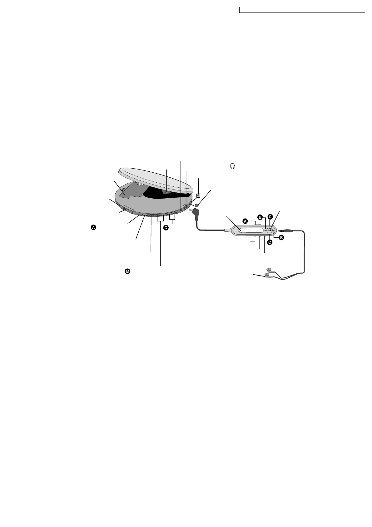
2 Location of Controls
Optical digital/line out jack
Rechargeable
battery
compartment
Charge lamp
Open switch
Hold switch
Play/Pause
Stop/Turn off
Lens
Headphone jack
Battery case terminal
Volume
control
· Wired remote control
(N2QCBD000046).........................................1 pc.
· External battery case
(RFA2666-H)..................................................1 pc.
· Rechargeable batteries (with case) for SL-CT720P/PC
(RFKFHFAZ09PM).........................................2 pcs.
· Rechargeable batteries (with case) for SL-CT720EB/EE/EG
(RFKFHFAZ09EM).........................................2 pcs.
)
(
DC IN jack
Display
Tone selection
Play mode selection
Memory/Recall/Display
Play/Stop/Turn off
Skip/Search
Earphones
3

SL-CT720P / SL-CT720PC / SL-CT720EB / SL-CT720EE / SL-CT720EG
3 Precaution of Laser Diode
· For SL-CT720P/PC
Caution:
This product utilizes a class 1 laser. Invisible laser radiation is emitted from the optical pick-up lens when the unit is turned
on:
1. Do not look directly into the pick-up lens.
2. Do not use optical instruments to look at the pick-up lens.
3. Do not adjust the preset variable resister on the optical pick-up.
4. Do not disassemble the optical pick-up unit.
5. If the optical pick-up is replaced, use the manufacture’s specified replacement pick-up only.
6. Use of control or adjustments or performance of procedures other than those specified herein may result in hazardous
radiation exposure.
· For SL-CT720EB/EE/EG
4
SL-CT720P / SL-CT720PC / SL-CT720EB / SL-CT720EE / SL-CT720EG
4 Handling Precautions for Traverse Deck
The laser diode in the traverse deck (optical pick-up) may break
down due to potential difference caused by static electricity of
clothes or human body.
So, be careful of electrostatic breakdown during repair of the
traverse deck (optical pick-up).
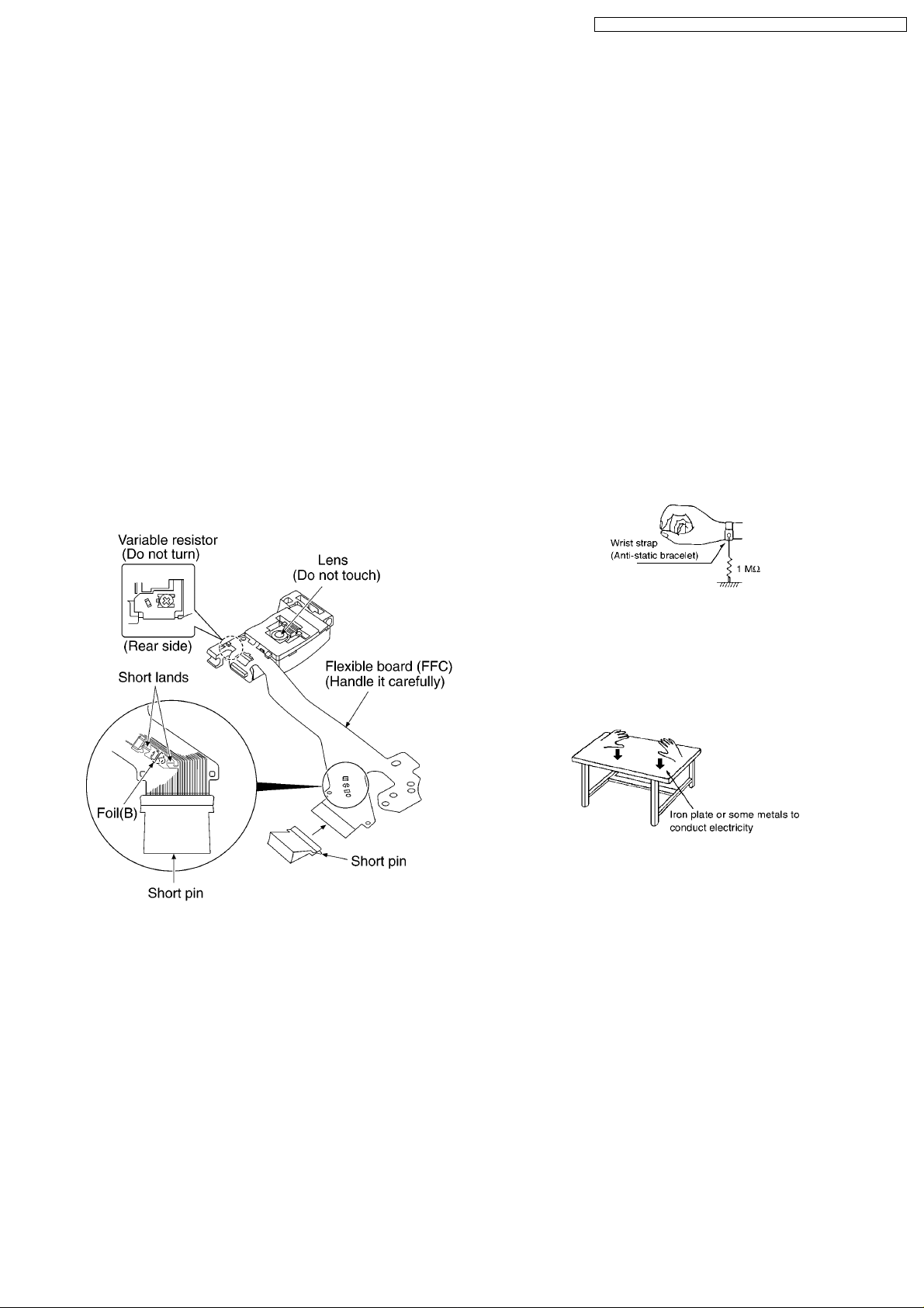
4.1. Handling of traverse deck
(optical pick-up)
1. Do not subject the optical pick-up to static electricity as it is
extremely sensitive to electrical shock.
2. To protect the laser diode against electrostatic breakdown,
be sure that the short land of the flexible board (FFC board)
should be short-circuit by solder before pulling out the FFC.
Then inserting a short pin or similar object into the tip of the
flexible board.
(Refer to Fig. 4-1.)
3. Take care not toapply excessive stress to the flexible board
(FFC board).
4. Do not turn the variable resistor (laser power adjustment). It
has already been adjusted. (Refer to Fig. 4-1.)
4.2. Caution when replacing
traverse deck
The new traverse deck short-circuits by the short pin, the foil
(B) and short lands to protect the laser diode against
electrostatic breakdown. Be sure to replace to new one
following procedures.
1. Remove the short pin from the FFC, and then connect it to
the connector.
2. Cut the foil (B). (Refer to Fig. 4-1.) (Take care not to make
contact with cutting point each other.)
3. Unsolder the short lands. (Refer to Fig. 4-1.)
4.3. Grounding for electrostatic
breakdown prevention
4.3.1. Human body grounding
Use the anti-static wrist strap to discharge the static electricity
from your body. (Refer to Fig. 4-2.)
Fig. 4-1.
Fig. 4-2.
4.3.2. Work table grounding
Put a conductive material (sheet) or steel sheet on the area
where the traverse deck (optical pick-up) is placed, and ground
the sheet. (Refer to Fig. 4-3.)
Fig. 4-3.
Caution:
The static electricity of your clothes will not be grounded
through the wrist strap.
So take care not to let your clothes touch the traverse deck
(optical pick-up).
5
SL-CT720P / SL-CT720PC / SL-CT720EB / SL-CT720EE / SL-CT720EG
5 Operation Checks and Component Replacement
Procedures
· This section describes procedures for checking the
operation of the major printed circuit boards and
replacing the main components.
· For reassembly after operation checks or replacement,
reverse the respective procedures. Special reassembly
procedures are described only when required.
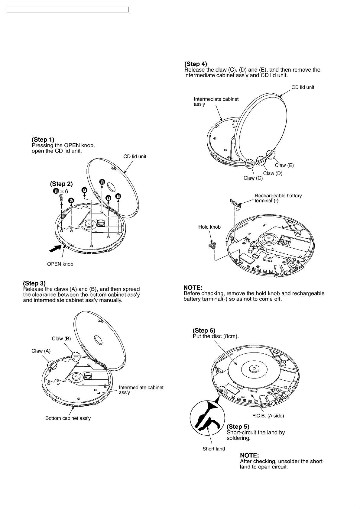
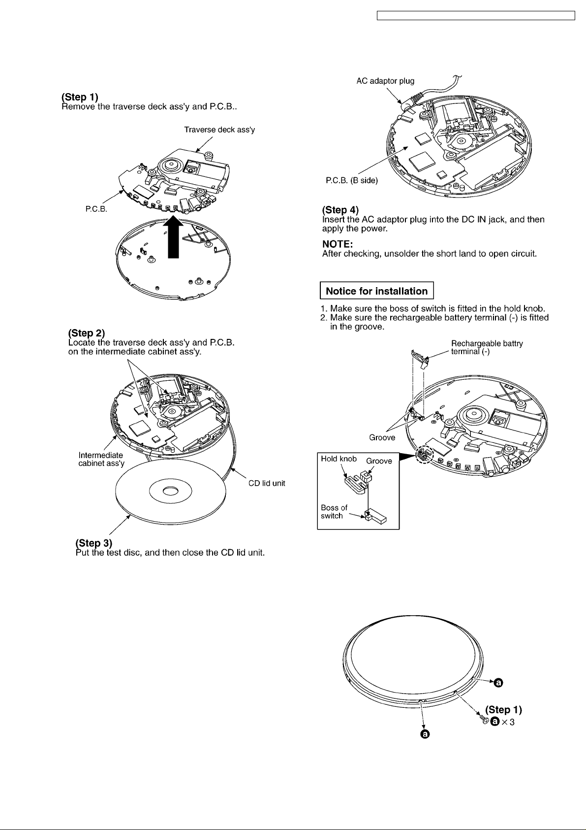
5.1. Checking for the P.C.B.
5.1.1. Checking for the P.C.B. (A side)
· Check the P.C.B. (A side) as shown below.
6
SL-CT720P / SL-CT720PC / SL-CT720EB / SL-CT720EE / SL-CT720EG
5.1.2. Checking for the P.C.B. (B side)
· Follow the (Step 1) - (Step 5) of item 5.1.1.
· Check the P.C.B. (B side) as shown below.
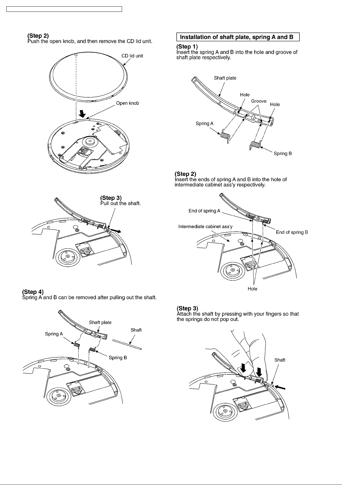
5.2. Replacement for the CD lid
unit, shaft plate, spring A and
spring B
7
SL-CT720P / SL-CT720PC / SL-CT720EB / SL-CT720EE / SL-CT720EG
8
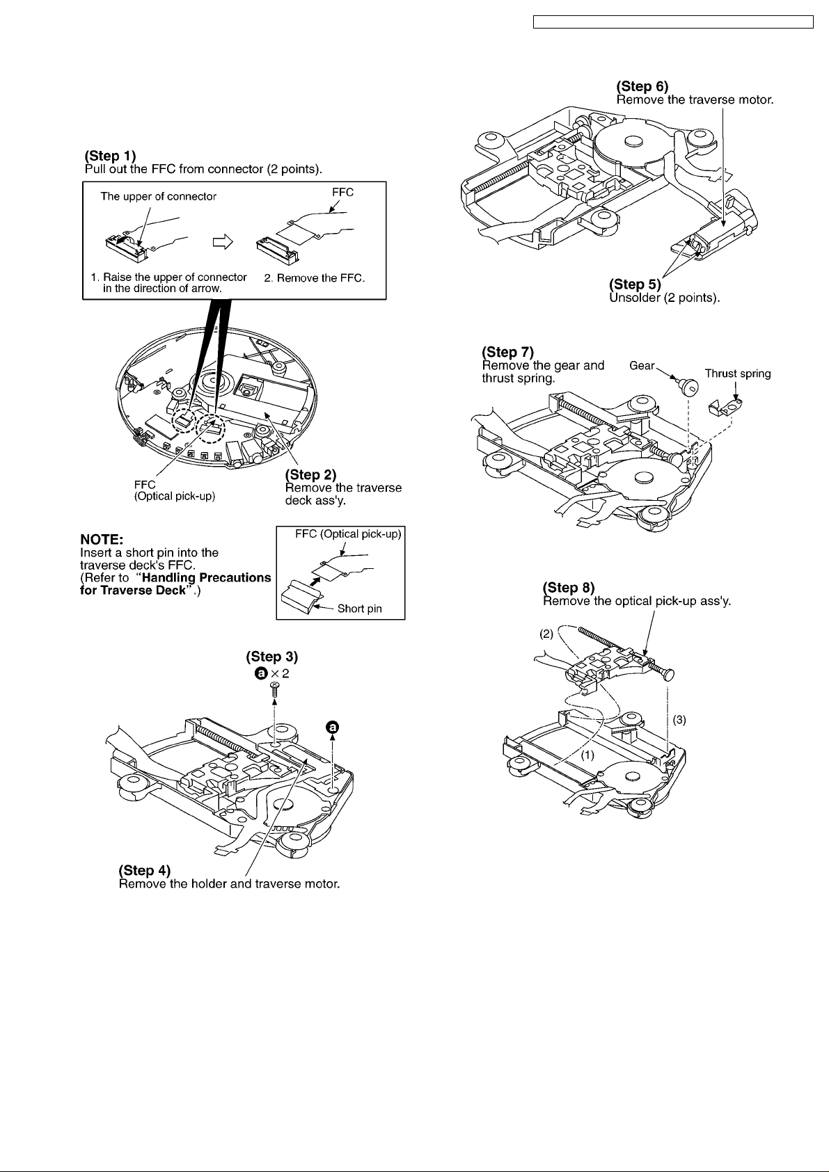
5.3. Replacement for the traverse
motor and optical pick-up
· Follow the (Step 1) - (Step 4) of item 5.1.1.
SL-CT720P / SL-CT720PC / SL-CT720EB / SL-CT720EE / SL-CT720EG
9

SL-CT720P / SL-CT720PC / SL-CT720EB / SL-CT720EE / SL-CT720EG
5.5. Replacement for the spindle
motor
· Follow the (Step 1) - (Step 4) of item 5.1.1.
· Follow the (Step 1) , (Step 2) of item 5.3.
5.4. Replacement for the rest
switch
· Follow the (Step 1) - (Step 4) of item 5.1.1.
· Follow the (Step 1) , (Step 2) of item 5.3.
6 Display of Self-Diagnostic
Function
This unit (SL-CT720) has self-diagnostic function. It may
display below-mentioned on the remote control display.
· The substance of self-diagnostic display.
Remote control display
(Press PLAY and STOP button. After 15 seconds, it is
displayed for 2 seconds.)
In case of this display, it may be causing for abnormally
movements of traverse deck, touching failure of REST detect
switch and coming off or cutting off the flexible P.C.B.. It is
necessary for confirmation or repair and replacement each
parts.
10

SL-CT720P / SL-CT720PC / SL-CT720EB / SL-CT720EE / SL-CT720EG
7 Checking the Operation Problems on the Traverse Deck
(Optical Pick-up)
Make sure to follow the procedures below to check the
operation problems of the traverse deck (optical pick-up) before
replacing it.
Replace the traverse deck only after the problem is identified.
7.1. Check the operations described below on the traverse deck after
replacing
7.1.1. Checking skip search
1. Play an ordinary musical program disc.
2. Press the skip button to check for normal skip search
operation (in both the forward and reverse directions).
7.1.2. Checking manual search
1. Play an ordinary musical program disc.
2. Press the manual search button to check for smooth
manual search operation at either low or high speed (in
both the forward and reverse directions).
7.1.3. Checking playability
1. Play the 0.7 mm black dot and the 0.7 mm wedge on the
playability test disc (SZZP1054C) and verify that no sound
skip or noise occurs.
2. Play the middle tracks of theuneven test disc (SZZP1056C)
and verify that no sound skip or noise occurs.
11
SL-CT720P / SL-CT720PC / SL-CT720EB / SL-CT720EE / SL-CT720EG
8 Automatic Adjustment Results Display Function
(Self-Check Function)
On the unit (SL-CT720), each automatic adjustment result are
displayed on the remote control display. This function is
convenient to check or identify which automatic adjustment
circuit is incorrect.
The followings are the contents of the automatic adjustment
result displays (Self-Check Function).
8.1. How to display automatic adjustment results
1. Load the test disc (SZZP1054C).
2. Press the
(SKIP/SEARCH) buttons simultaneously and hold them,
and additionally press the
(SKIP/SEARCH) and
(PLAY/PAUSE) button.
3. Press the
4. An automatic adjustment result is displayed on the remote
control display.
(STOP/TURN OFF) button once.
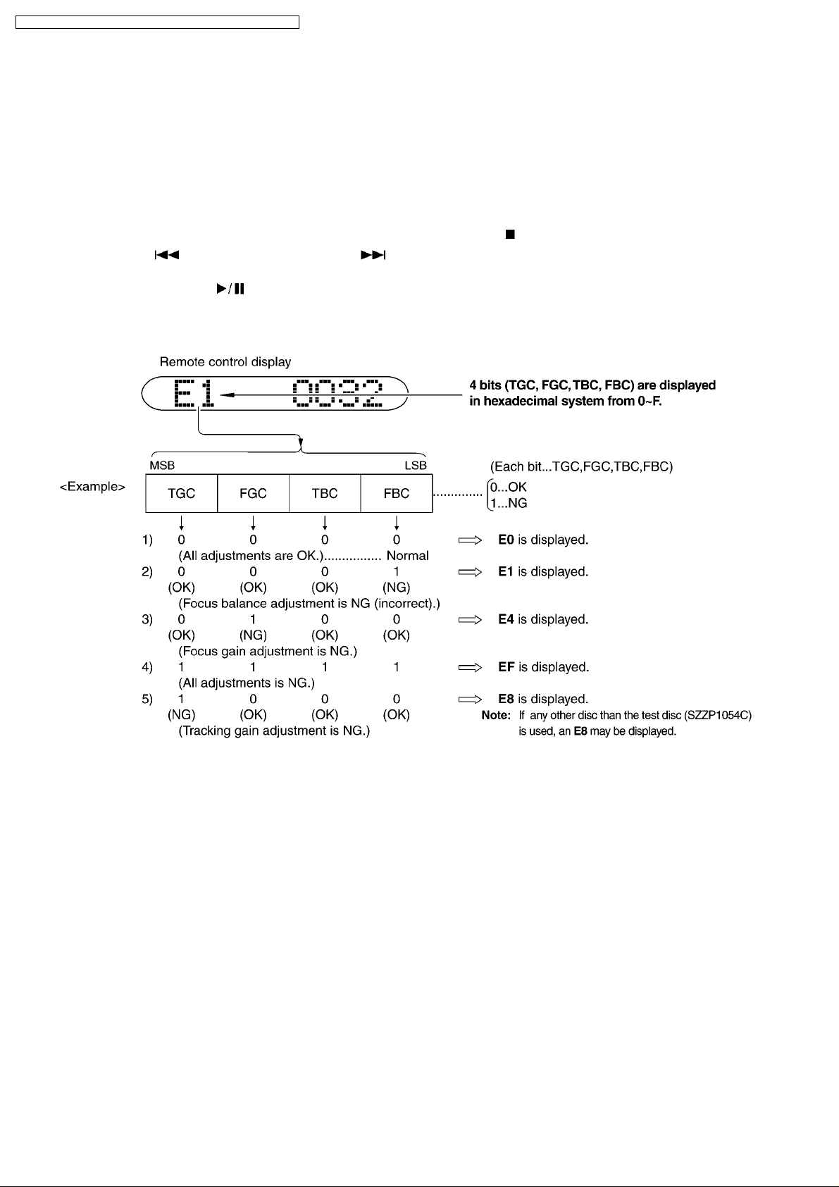
8.2. Display of automatic adjustment results (Self-Check Function)
<Example>
Follow the below steps when E1 is displayed.
(Cause: Focus balance (FBC) is set beyond the limit.)
· Check if
1. the waveform or voltage of the focus servo circuit is
correct, and
2. the optical pick-up returns to the normal state by
exchanging the traverse deck.
Follow the below steps when E4 is displayed.
(Cause: Focus gain (FGC) is set beyond the limit.)
· Check if
1. the waveform or voltage of the focus servo circuit is
correct,
2. the focus coil of the optical pick-up is correct (around 8
ohms), and
3. the optical pick-up returns to the normal state by
exchanging the traverse deck.
Follow the below steps when EF is displayed.
(Cause: All adjustments (TGC, FGC, TBC, FBC) are set
beyond the limit.)
· Check if
1. the optical pick-up returns to the normal state by
exchanging the traverse deck, and
2. the waveform or voltage of the servo ICs are correct.
Note:
It is not always necessary to exchange the traverse
deck when an error message is displayed.
Be sure to check if the circuit is defective or not before
exchanging the traverse deck.
Note:
If any other disc than the test disc (SZZP1054C) is used, an
error message may be displayed.
This is not a malfunction.
12
 Loading...