

Panasonic SLCT-582-VEE Service manual

AD0502017C2
Portable CD Player
SL-CT582VEE
Colour
(H)..........Gray Type
(S)..........Silver Type
1
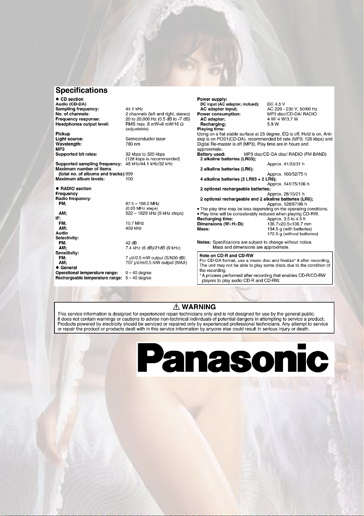
SPECIFICATIONS
1
1. Accessories
- AC adaptor
(RFEA419E-M)................................................1 pc.
- Stereo earphones
(L0BAB0000183)...........................................1 pc.
2
- Wired remote control
(N2QCBD000011)........................................1 pc.
- External battery case
(RFA2666-H)..................................................1 pc.
2. Location of Controls
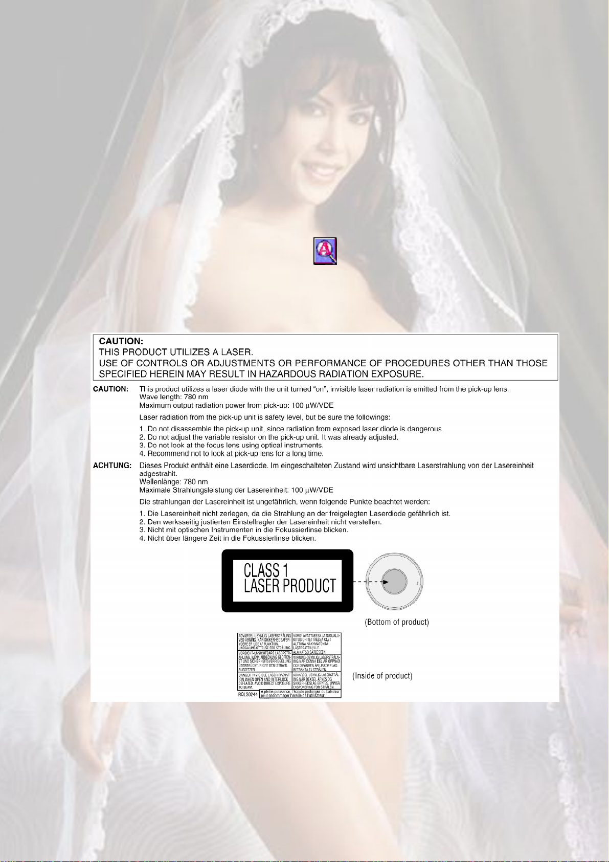
3. Precaution of Laser Diode
4. Handling Precautions for Traverse Deck
3

The laser diode in the traverse deck (optical pick-up) may break down due to
potential difference caused by static electricity of clothes or human body.
So, be careful of electrostatic breakdown during repair of the traverse deck
(optical pick-up).
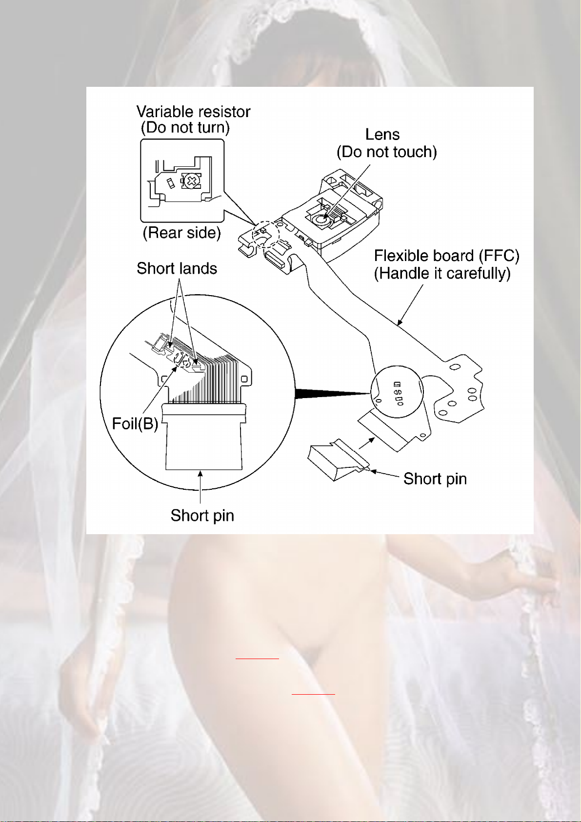
4.1. Handling of traverse deck (optical pick-up)
1. Do not subject the optical pick-up to static electricity as it is extremely
sensitive to electrical shock.
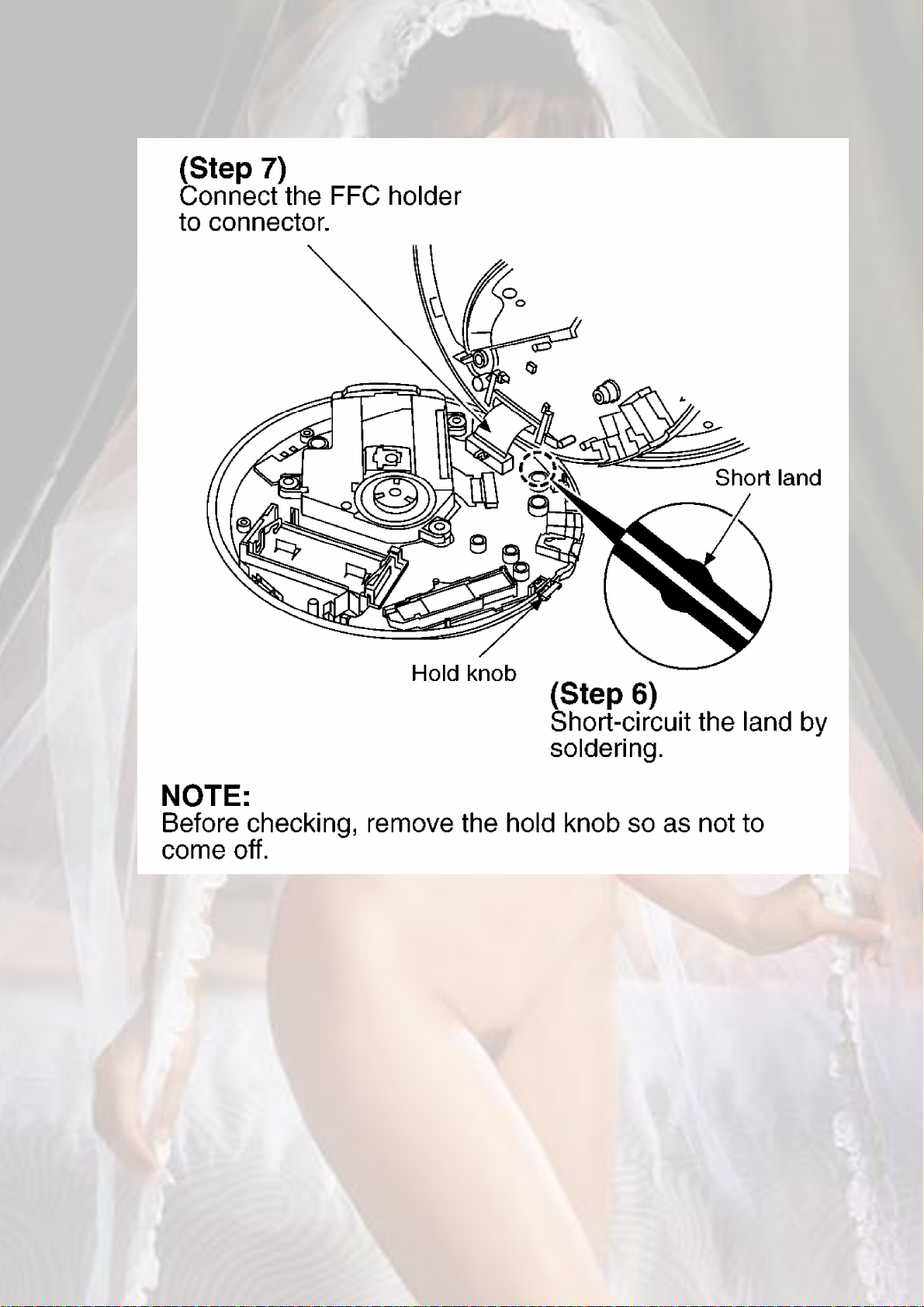
2. To protect the laser diode against electrostatic breakdown, be sure that the
short land of the flexible board (FFC board) should be short-circuit by solder
before pulling out the FFC. Then inserting a short pin or similar object into the
tip of the flexible board.
(Refer to Fig. 4-1.)
3. Take care not to apply excessive stress to the flexible board (FFC board).
4. Do not turn the variable resistor (laser power adjustment). It has already been
adjusted. (Refer to Fig. 4-1.)
Fig. 4-1.
4
4.2. Caution when replacing traverse deck
The new traverse deck short-circuits by the short pin, the foil (B) and short lands
to protect the laser diode against electrostatic breakdown. Be sure to replace to
new one following procedures.
1. Remove the short pin from the FFC, and then connect it to the connector.
2. Cut the foil (B). (Refer to Fig. 4-1.) (Take care not to make contact with cutting
point each other.)
3. Unsolder the short lands. (Refer to Fig. 4-1.)
4.3. Grounding for electrostatic breakdown prevention
5
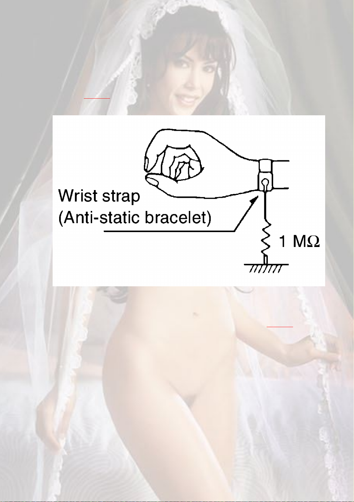
4.3.1. Human body grounding
Use the anti-static wrist strap to discharge the static electricity from your body.
(Refer to Fig. 4-2.)
Fig. 4-2.
4.3.2. Work table grounding
Put a conductive material (sheet) or steel sheet on the area where the traverse
deck (optical pick-up) is placed, and ground the sheet. (Refer to Fig. 4-3.)
Fig. 4-3.
6

Caution:
The static electricity of your clothes will not be grounded through the wrist
strap.
So take care not to let your clothes touch the traverse deck (optical pick-up).
5. Operation Checks and Component Replacement
Procedures
- This section describes procedures for checking the operation of the major
printed circuit boards and replacing the main components.
- For reassembly after operation checks or replacement, reverse the respective
procedures. Special reassembly procedures are described only when required.
5.1. Checking for the P.C.B.
5.1.1. Checking for the P.C.B. (A side)
78910111213
- Check the P.C.B. (A side) as shown below.
5.1.2. Checking for the P.C.B. (B side)
- Follow the (Step 1) - (Step 7) of item 5.1.1.
14
15
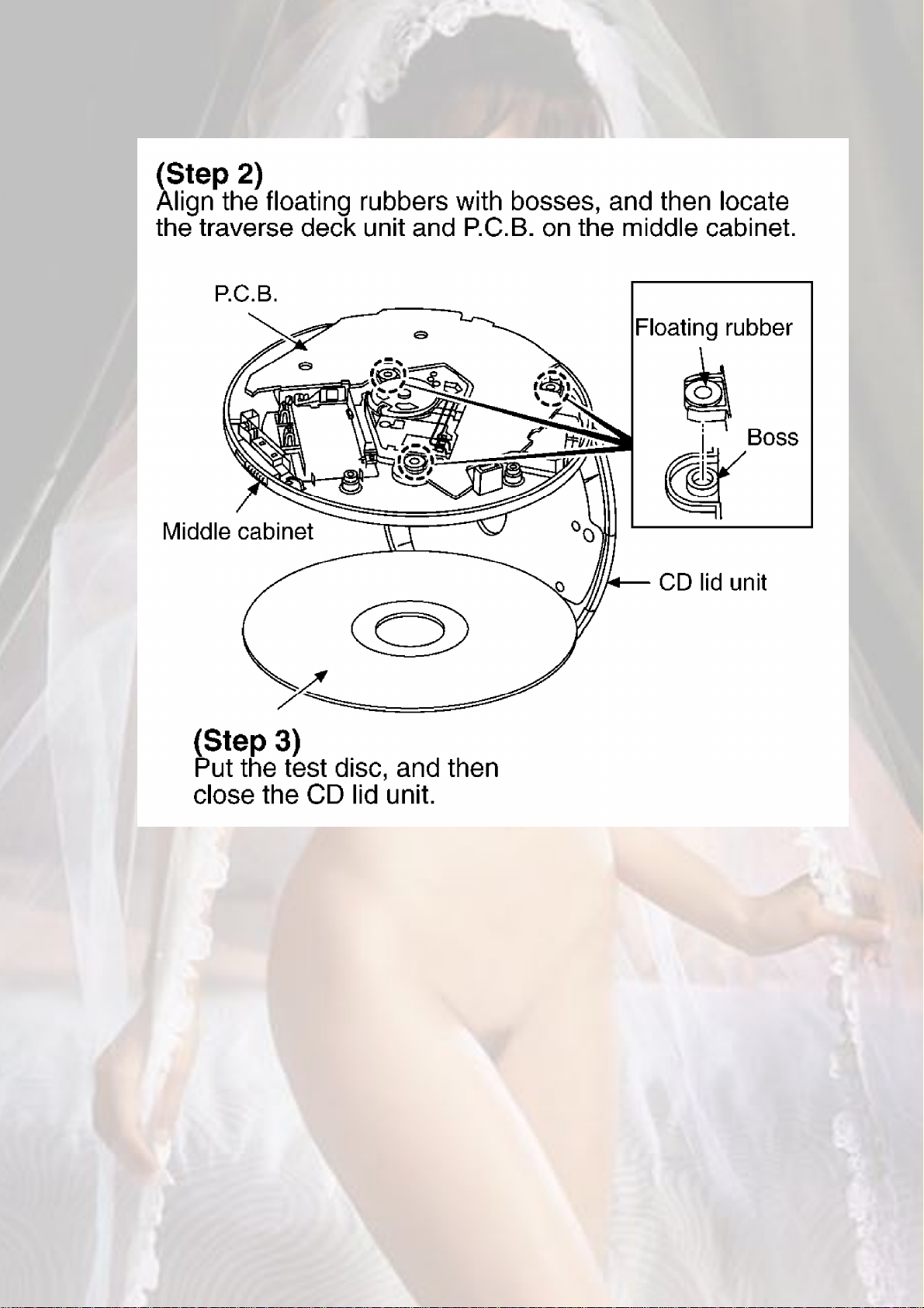
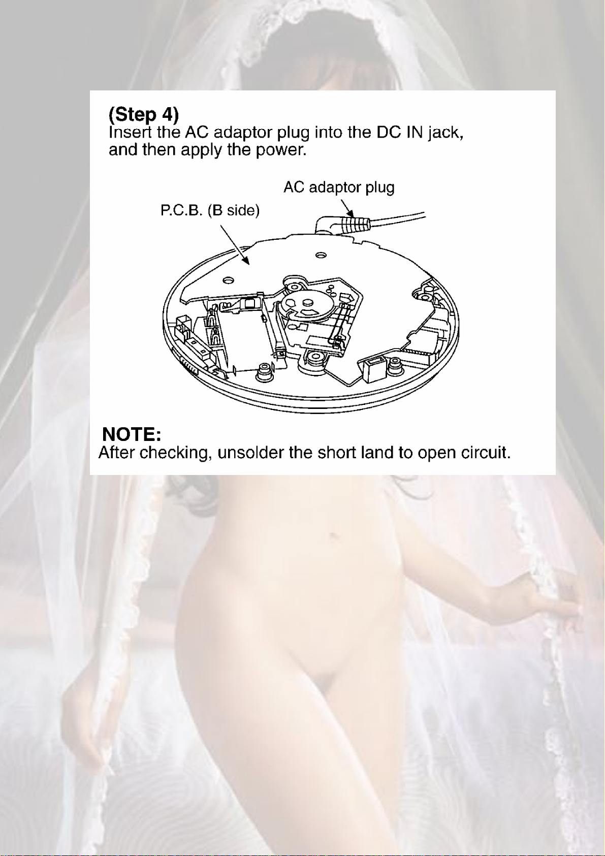
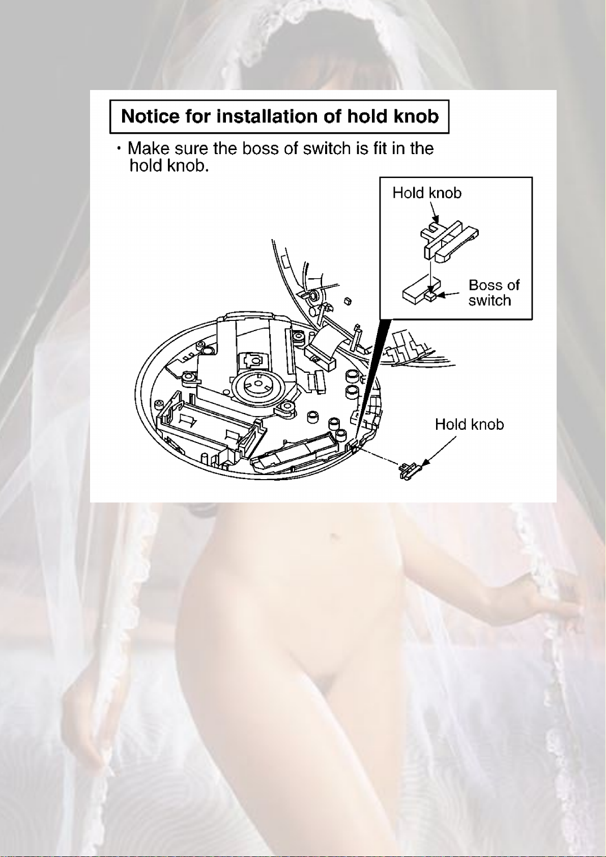
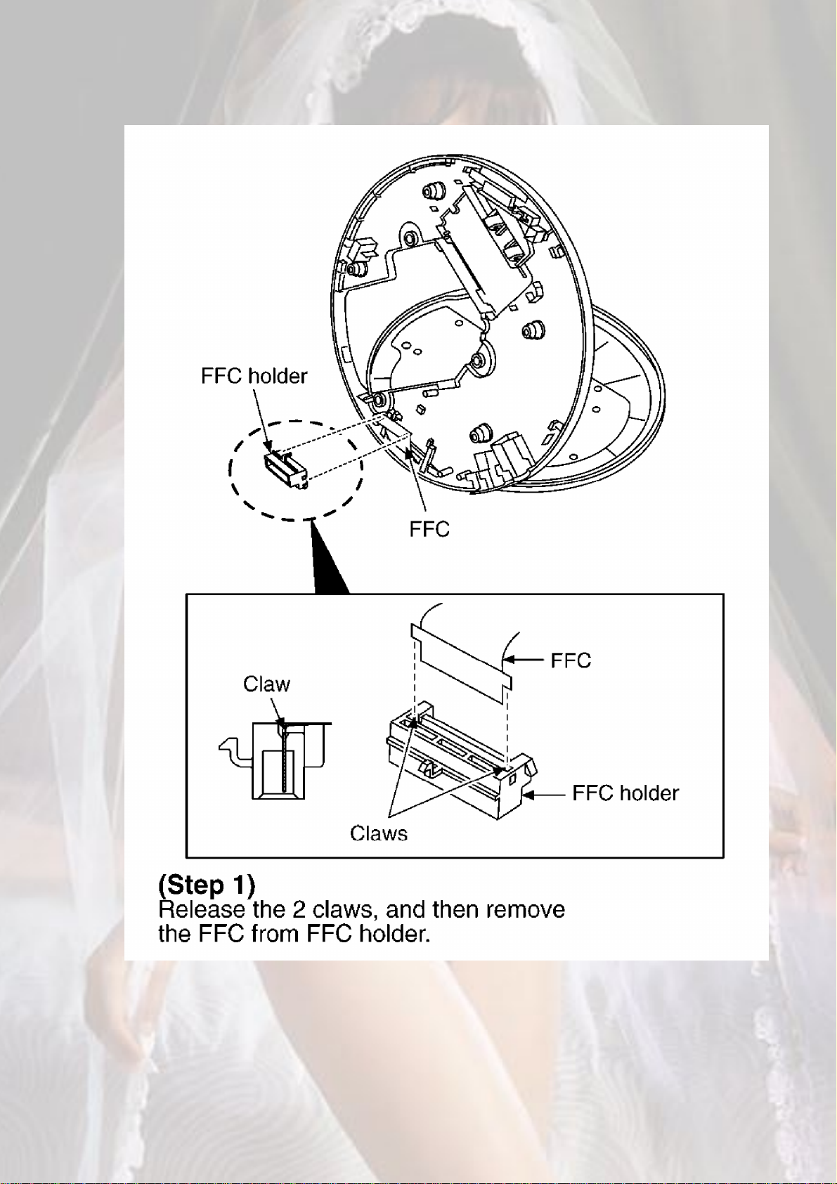
- Check the P.C.B. (B side) as shown below.
16
17
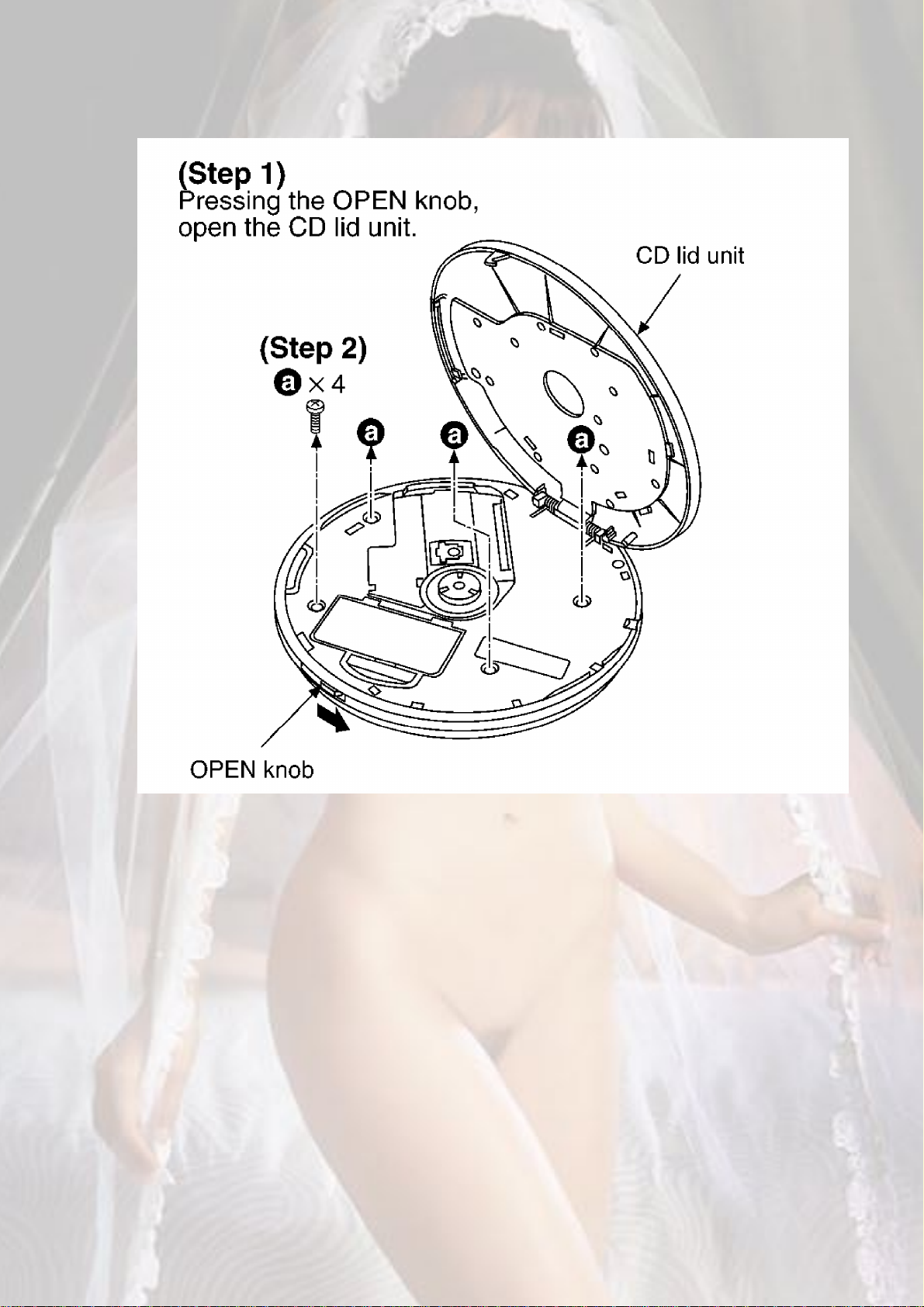
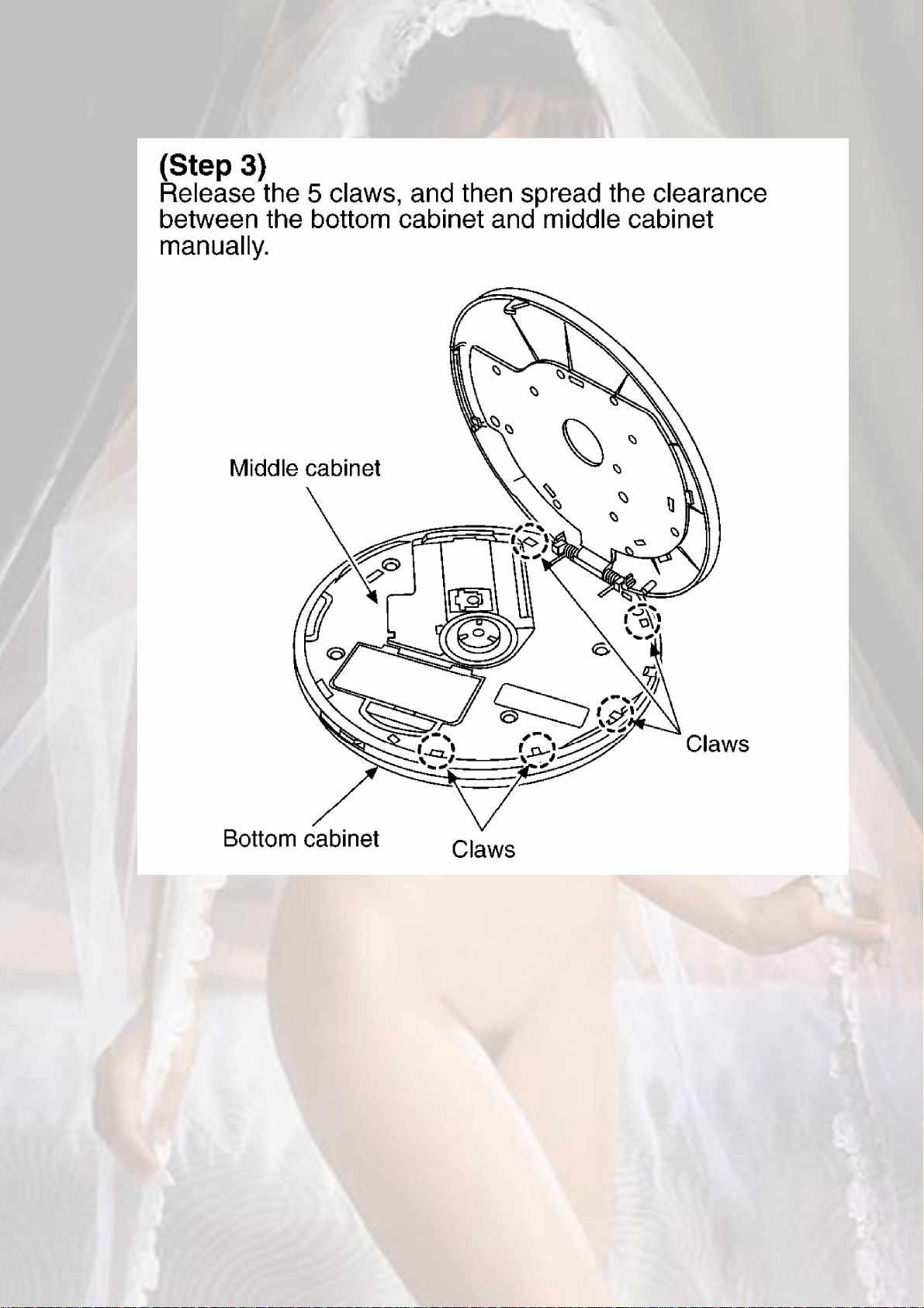
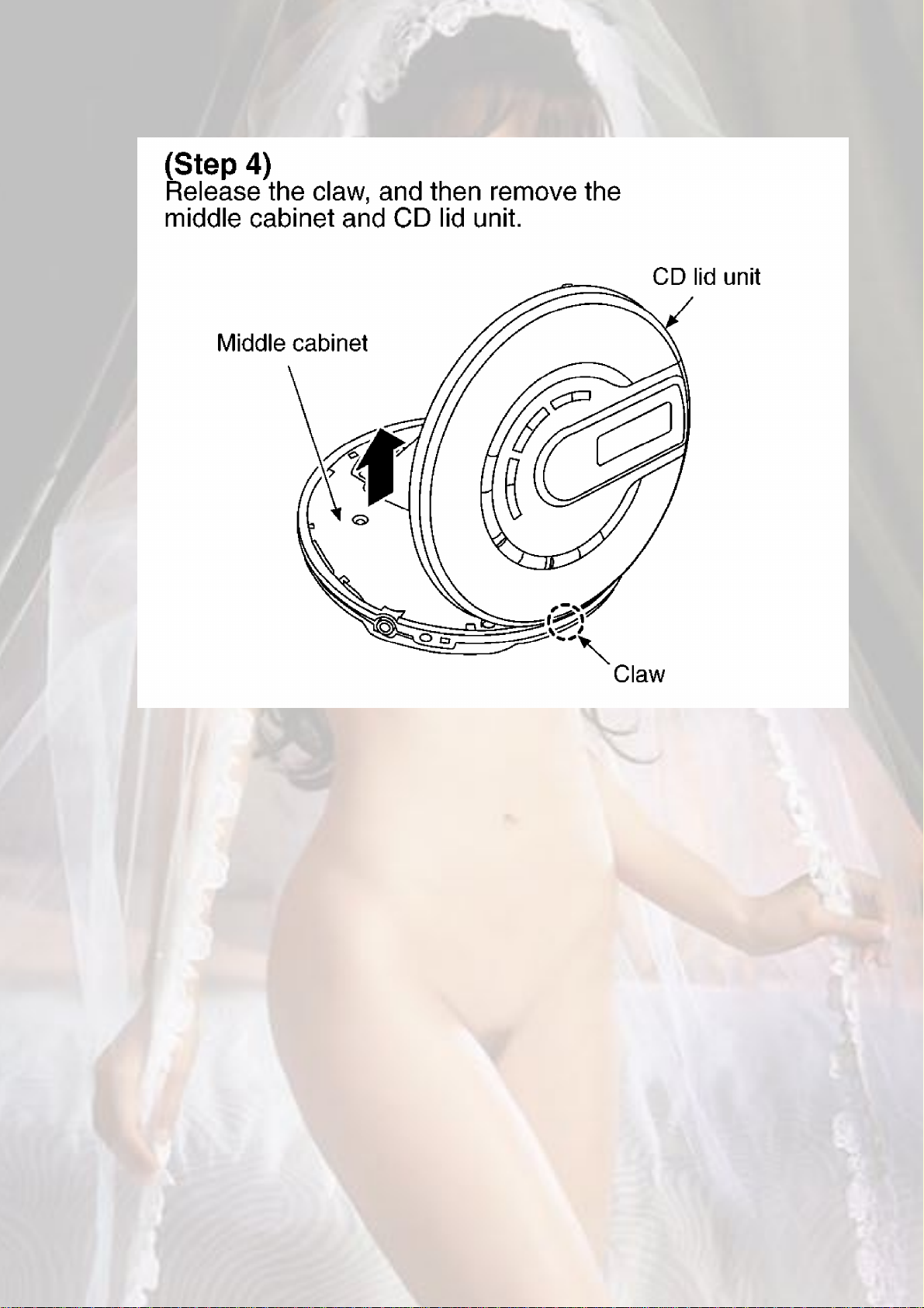
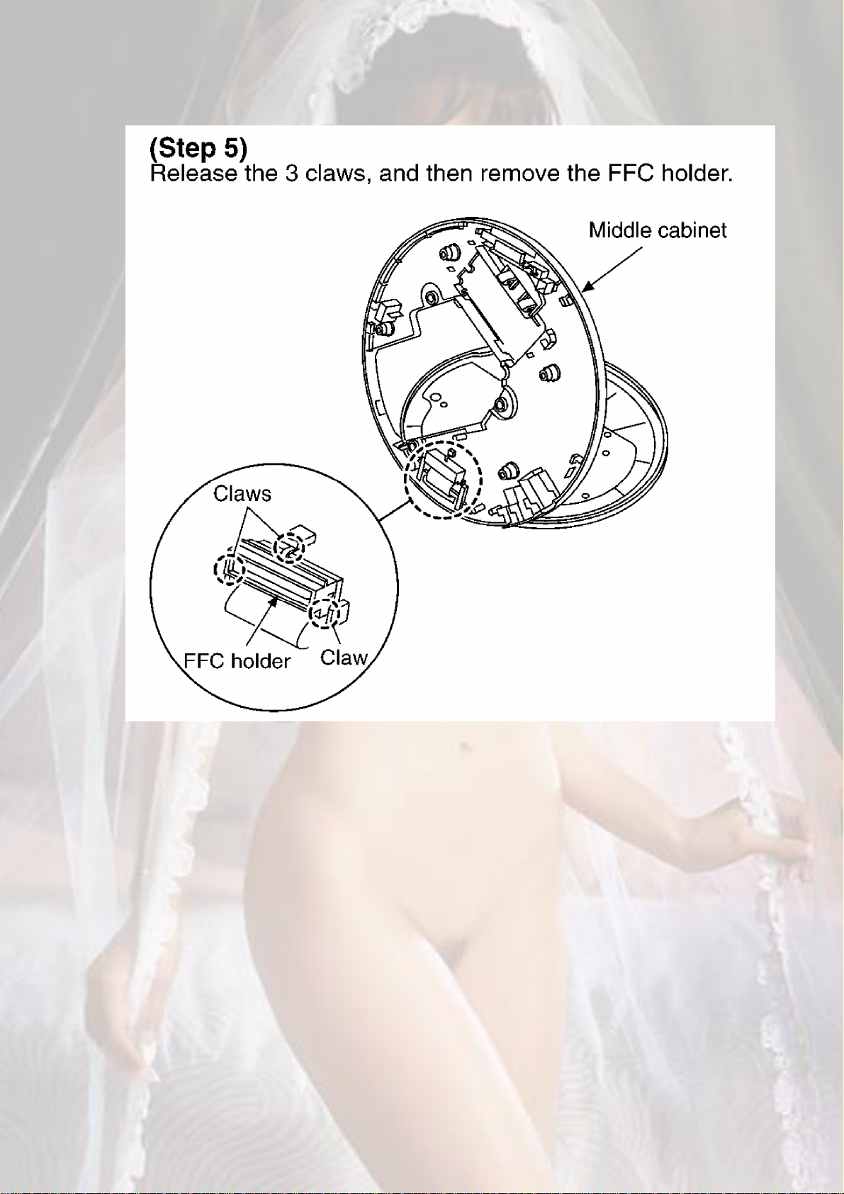
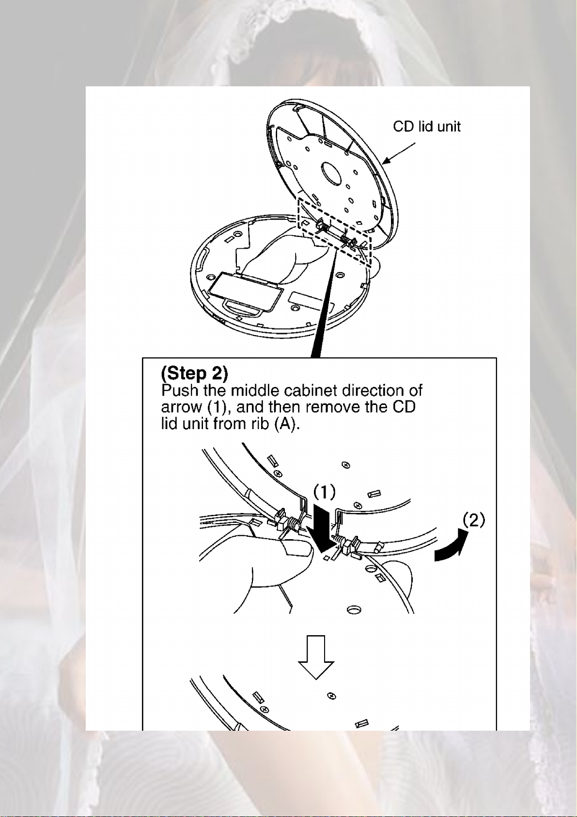
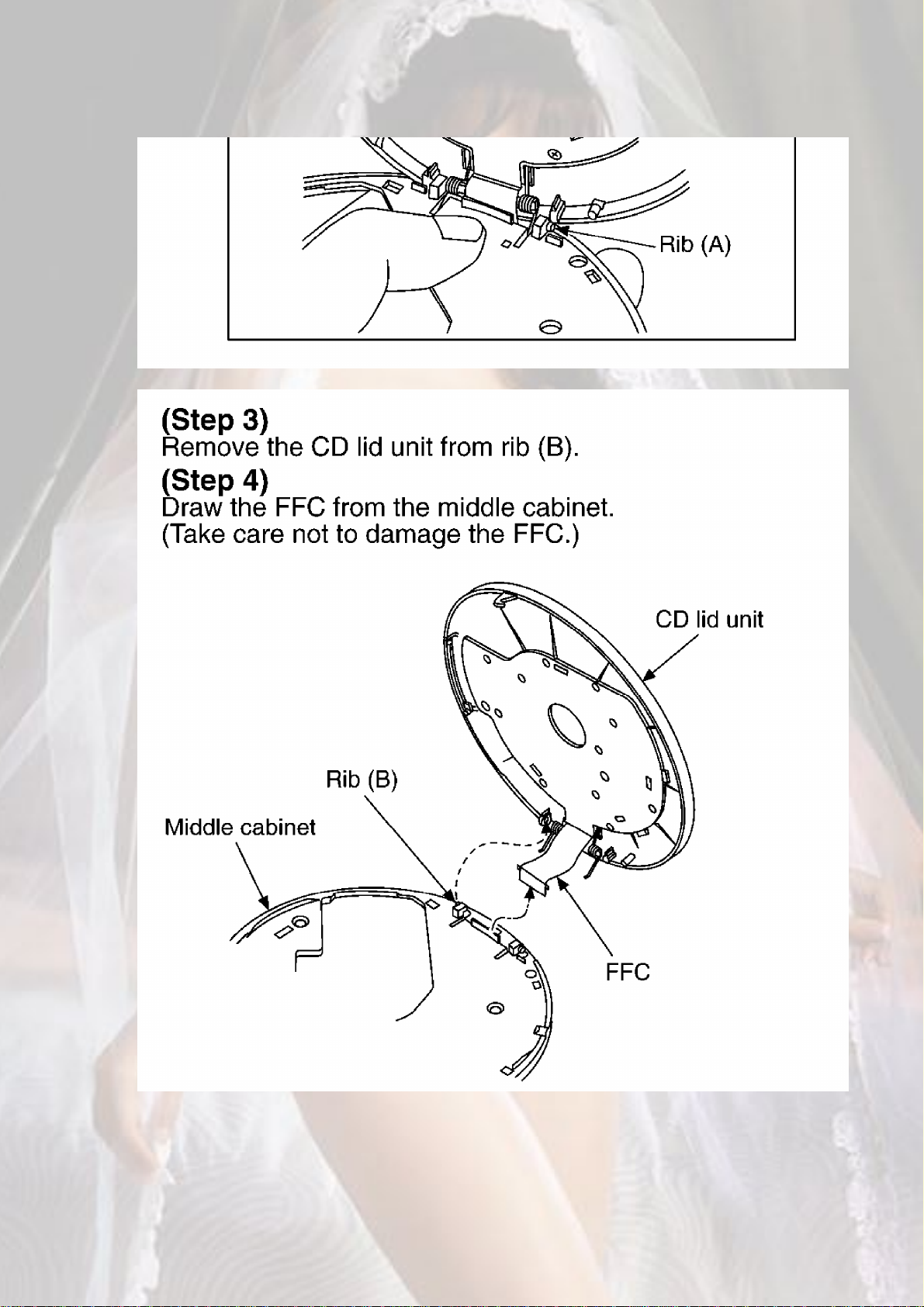
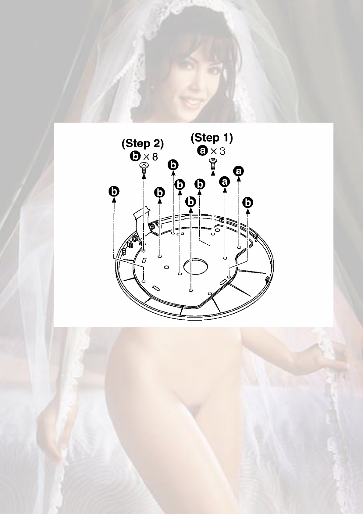
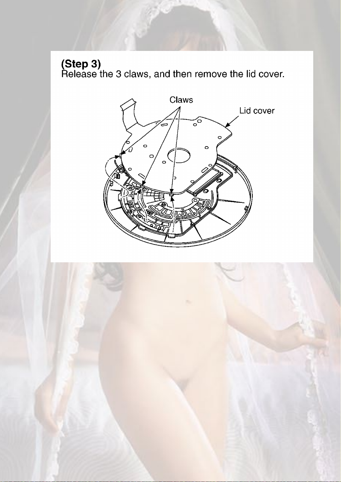
5.2. Replacement for the CD lid unit
- Follow the (Step 1) - (Step 5) of item 5.1.1.
181920
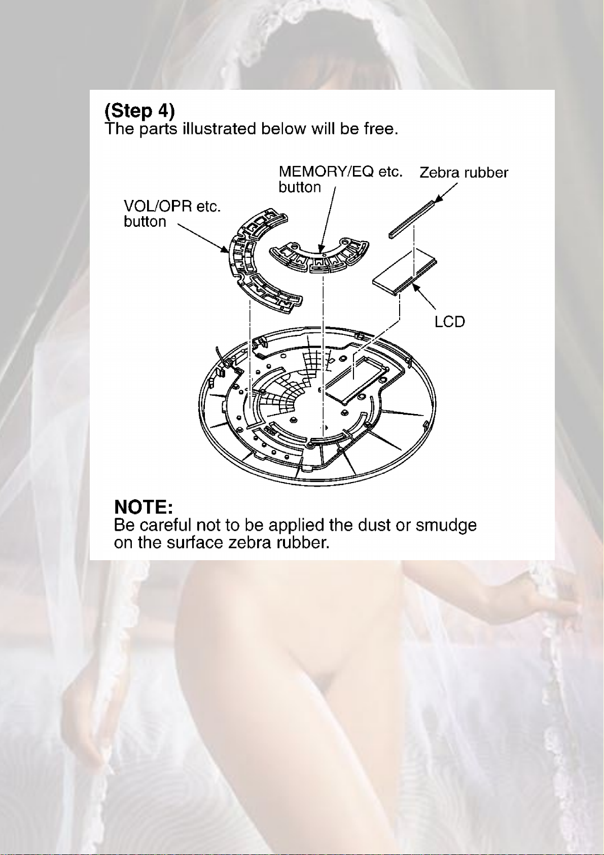
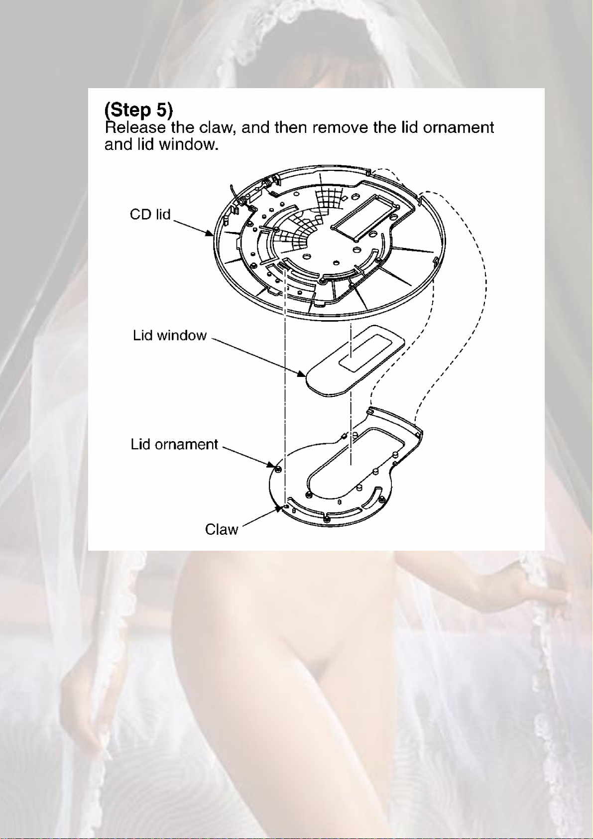
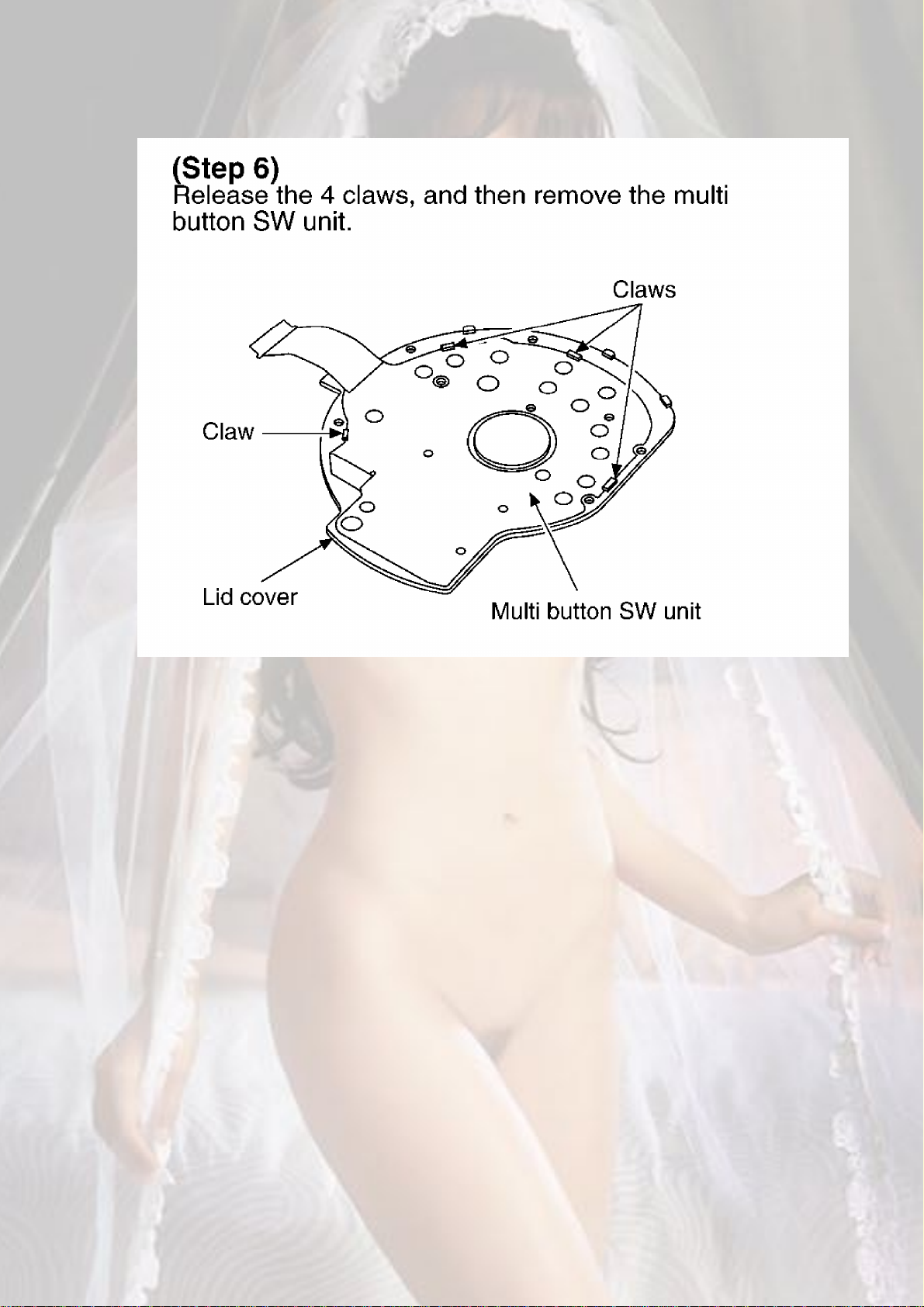
5.3. Replacement for the LCD, VOL/OPR etc. button,
21
MEMORY/EQ etc. button, Lid ornament and multi button SW
unit
- Follow the (Step 1) - (Step 5) of item 5.1.1.
- Follow the (Step 1) - (Step 4) of item 5.2.
222324
25
5.4. Replacement for the retainer plate, open spring 1 and
open spring 2
- Follow the (Step 1) - (Step 5) of item 5.1.1.
- Follow the (Step 1) - (Step 4) of item 5.2.
26
 Loading...