

Panasonic SL 800 User Manual
USER'S MANUAL
CAUTION
Read all precautions and instructions in this manual before using
this equipment. Keep this manual
for future reference.
Serial
Number
Decal
Model No. NTEVEX79830
Serial No.
QUESTIONS?
As a manufacturer, we are committed to providing complete
customer satisfaction. If you have
questions, or if there are missing
parts, please call:
Or write:
ICON Health & Fitness, Ltd.
Unit 4
Revie Road Industrial Estate
Revie Road
Beeston
Leeds
LS11 8JG
email: csuk@iconeurope.com
08457 089 009
Class HC Fitness Product

2
TABLE OF CONTENTS
IMPORTANT PRECAUTIONS . . . . . . . . . . . . . . . . . . . . . . . . . . . . . . . . . . . . . . . . . . . . . . . . . . . . . . . . . . . . . . . .3
BEFORE YOU BEGIN . . . . . . . . . . . . . . . . . . . . . . . . . . . . . . . . . . . . . . . . . . . . . . . . . . . . . . . . . . . . . . . . . . . . . .4
ASSEMBLY . . . . . . . . . . . . . . . . . . . . . . . . . . . . . . . . . . . . . . . . . . . . . . . . . . . . . . . . . . . . . . . . . . . . . . . . . . . . . . .5
HOW TO USE THE CHEST PULSE SENSOR . . . . . . . . . . . . . . . . . . . . . . . . . . . . . . . . . . . . . . . . . . . . . . . . . . .9
HOW TO OPERATE THE EXERCISE CYCLE . . . . . . . . . . . . . . . . . . . . . . . . . . . . . . . . . . . . . . . . . . . . . . . . . . .11
MAINTENANCE AND TROUBLESHOOTING . . . . . . . . . . . . . . . . . . . . . . . . . . . . . . . . . . . . . . . . . . . . . . . . . . .23
EXERCISE GUIDELINES . . . . . . . . . . . . . . . . . . . . . . . . . . . . . . . . . . . . . . . . . . . . . . . . . . . . . . . . . . . . . . . . . . .24
PART LIST . . . . . . . . . . . . . . . . . . . . . . . . . . . . . . . . . . . . . . . . . . . . . . . . . . . . . . . . . . . . . . . . . . . . . . . . . . . . . .26
EXPLODED DRAWING . . . . . . . . . . . . . . . . . . . . . . . . . . . . . . . . . . . . . . . . . . . . . . . . . . . . . . . . . . . . . . . . . . . .27
ORDERING REPLACEMENT PARTS . . . . . . . . . . . . . . . . . . . . . . . . . . . . . . . . . . . . . . . . . . . . . . . . . .Back Cover
NordicTrack is a registered trademark of ICON Health & Fitness, Inc.

3
IMPORTANT PRECAUTIONS
WARNING:
To reduce the risk of serious injury, read the following important precau-
tions before using the exercise cycle.
1. Read all instructions in this manual before
using the exercise cycle. Use the exercise
cycle only as described.
2. It is the responsibility of the owner to
ensure that all users of the exercise cycle
are adequately informed of all precautions.
3. Use the exercise cycle indoors on a level
surface. Keep the exercise cycle away from
moisture and dust. Place a mat under the
exercise cycle to protect the floor or carpet.
4. Inspect and properly tighten all parts regularly. Replace any worn parts immediately.
5. Keep children under the age of 12 and pets
away from the exercise cycle at all times.
6. The exercise cycle should not be used by
persons weighing more than 115 kg (250
lbs).
7. Wear suitable clothing when using the
exercise cycle; do not wear loose clothing
that could become caught on the exercise
cycle. Always wear athletic shoes.
8. Always keep your back straight when using
the exercise cycle. Do not arch your back.
9. If you feel pain or dizziness whilst exercising, stop immediately and cool down.
10. The pulse sensors are not medical devices.
Various factors, including the user's movement, may affect the accuracy of heart rate
readings. The pulse sensors are intended
only as exercise aids in determining heart
rate trends in general.
11. The exercise cycle is intended for in-home
use only. Do not use the exercise cycle in a
commercial, rental, or institutional setting.
WARNING:Before beginning this or any exercise program, consult your physician. This
is especially important for persons over the age of 35 or persons with pre-existing health problems.
Read all instructions before using. ICON assumes no responsibility for personal injury or property
damage sustained by or through the use of this product.
4
Congratulations for selecting the new NordicTrack
®
SL 800 exercise cycle. Cycling is one of the most
effective exercises for increasing cardiovascular fitness, building endurance, and toning the entire body.
The NordicTrack
®
SL 800 offers an impressive array
of features designed to let you enjoy this healthful
exercise in the comfort and privacy of your home.
For your benefit, read this manual carefully before
using the exercise cycle. If you have questions after
reading this manual, please call our Customer Service
Department at 08457 089 009. To help us assist you,
mention the product model number and serial number
when calling. The model number is NTEVEX79830.
The serial number can be found on a decal attached
to the exercise cycle (see the front cover of this manual for the location of the decal).
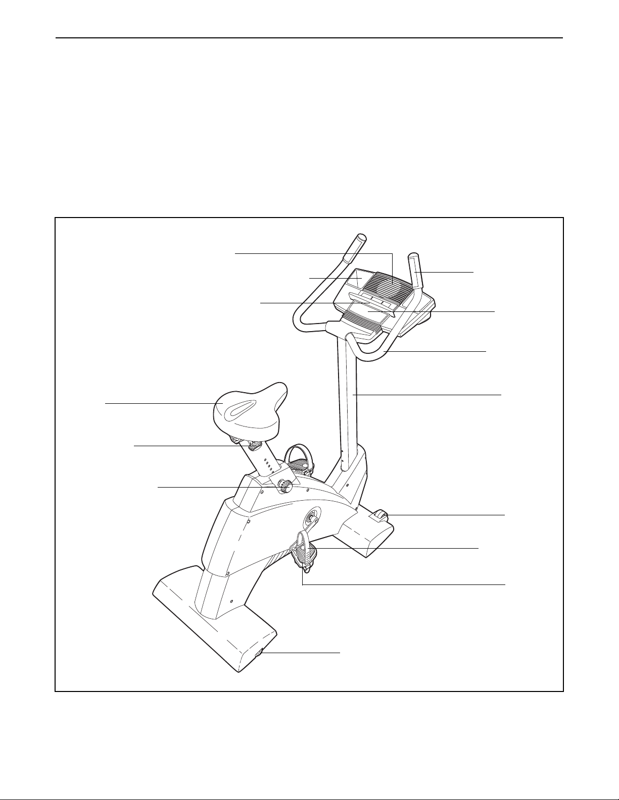
Before reading further, please familiarise yourself with
the parts that are labeled in the drawing below.
Handgrip
Pulse Sensor
Handlebar
Fan
Upright
Water Bottle Holder*
*No water bottle
is included
FRONT
REAR
Seat
Pedal Strap
Wheel
Pedal
Console
Bookrack
Seat Post Knob
Seat Knob
Leveling Foot
RIGHT SIDE
BEFORE YOU BEGIN
5
ASSEMBLY
Assembly requires two persons. Place all parts of the exercise cycle in a cleared area and remove the packing
materials. Do not dispose of the packing materials until assembly is completed.
Assembly requires the included tools and your own adjustable spanner .
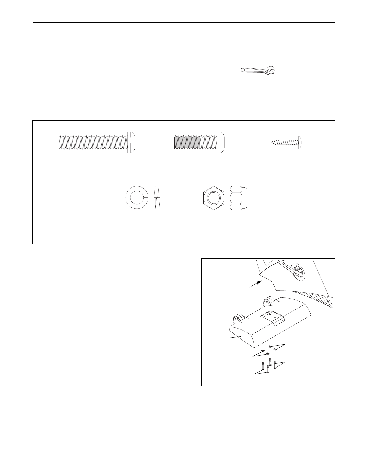
Use the drawings below to identify the small parts used in assembly. The number in parentheses below each
drawing refers to the key number of the part, from the PART LIST on page 26. The second number refers to the
quantity needed for assembly. Note: Some small parts may have been pre-attached for shipping. If a part is
not in the parts bag, check to see if it has been pre-assembled.
1. Identify the Front Stabiliser (15). Whilst another person
lifts the front of the Frame (1), attach the Front
Stabiliser to the Frame with four M8 x 40mm Button
Screws (54) and four M8 Split Washers (55).
15
1
55
55
54
54
1
M8 x 40mm Button Screw
(54)–12
M8 Split Washer
(55)–18
M8 x 25mm Patch Screw
(59)–4
Locknut (63)–4
M4 x 16mm Screw
(57)–4
M8 Nylon
6
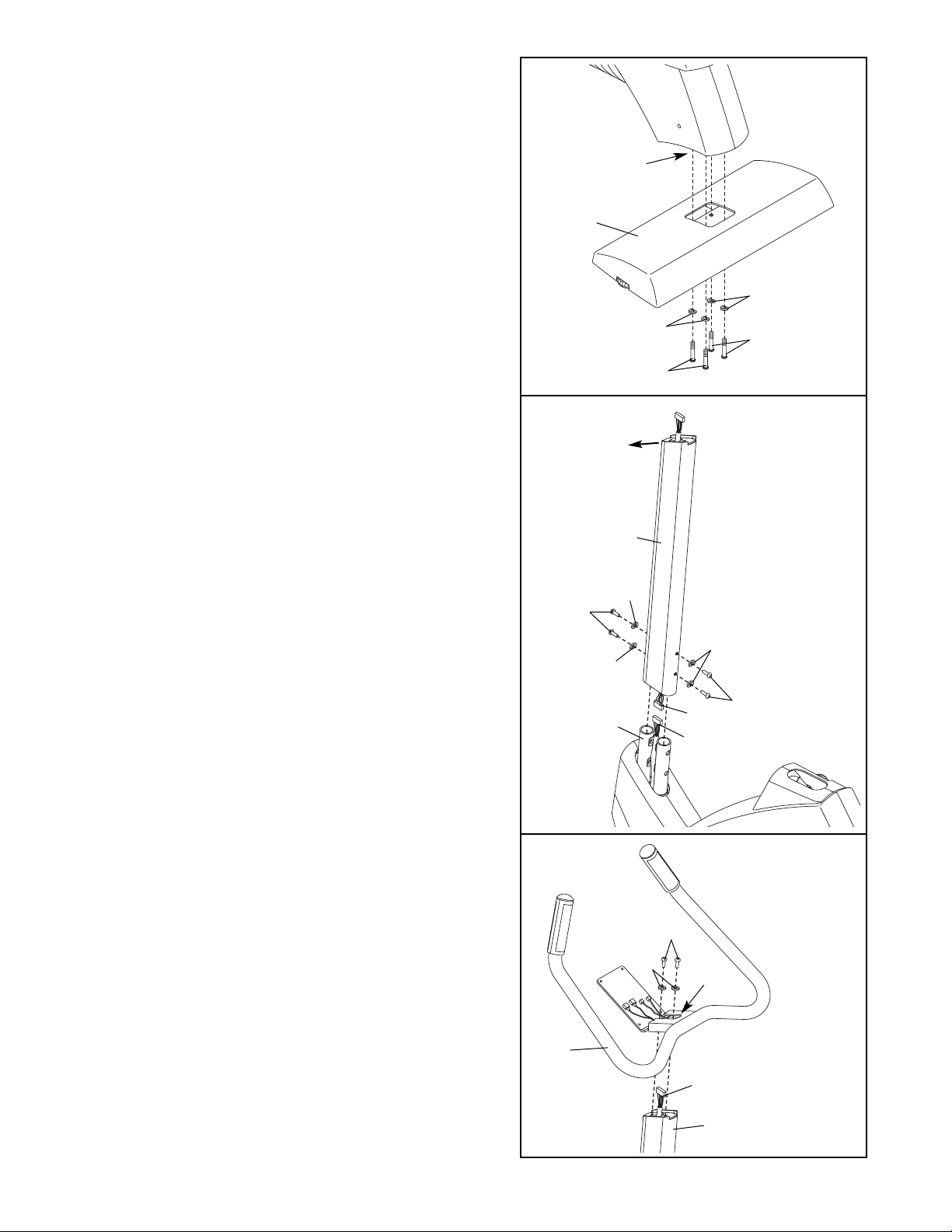
2. Whilst another person lifts the rear of the Frame (1),
attach the Rear Stabiliser (16) to the Frame with four
M8 x 40mm Button Screws (54) and four M8 Split
Washers (55).
3
2
42
43
54
54
55
55
55
1
3. Whilst another person holds the Upright (2) in the posi-
tion shown, connect the Upper Wire Harness (42) to
the Lower Wire Harness (43).
Carefully pull the
upper end of the Upper Wire Harness to remove
the slack from the Wire Harnesses.
Make sure that the Upright (2) is turned so the top
slopes down in the direction shown. Slide the
Upright onto the Frame (1). Be careful to avoid pinching the Wire Harnesses (42, 43). Attach the Upright to
the Frame with four M8 x 40mm Button Screws (54)
and four M8 Split Washers (55).
4. Hold the Handlebar (3) near the Upright (2). Feed the
Upper Wire Harness (42) up through the indicated hole
in the Handlebar. Attach the Handlebar to the Upright
with two M8 x 25mm Patch Screws (59) and two M8
Split Washers (55). Be careful to avoid pinching the
Upper Wire Harness.
3
Hole
2
42
59
55
4
Do not pinch the
Wire Harnesses
(42, 43) during
this step.
Top must
slope down in
this direction.
Do not pinch
the Upper
Wire Harness
(42) during
this step.
16
1
55
55
54
54
2
7
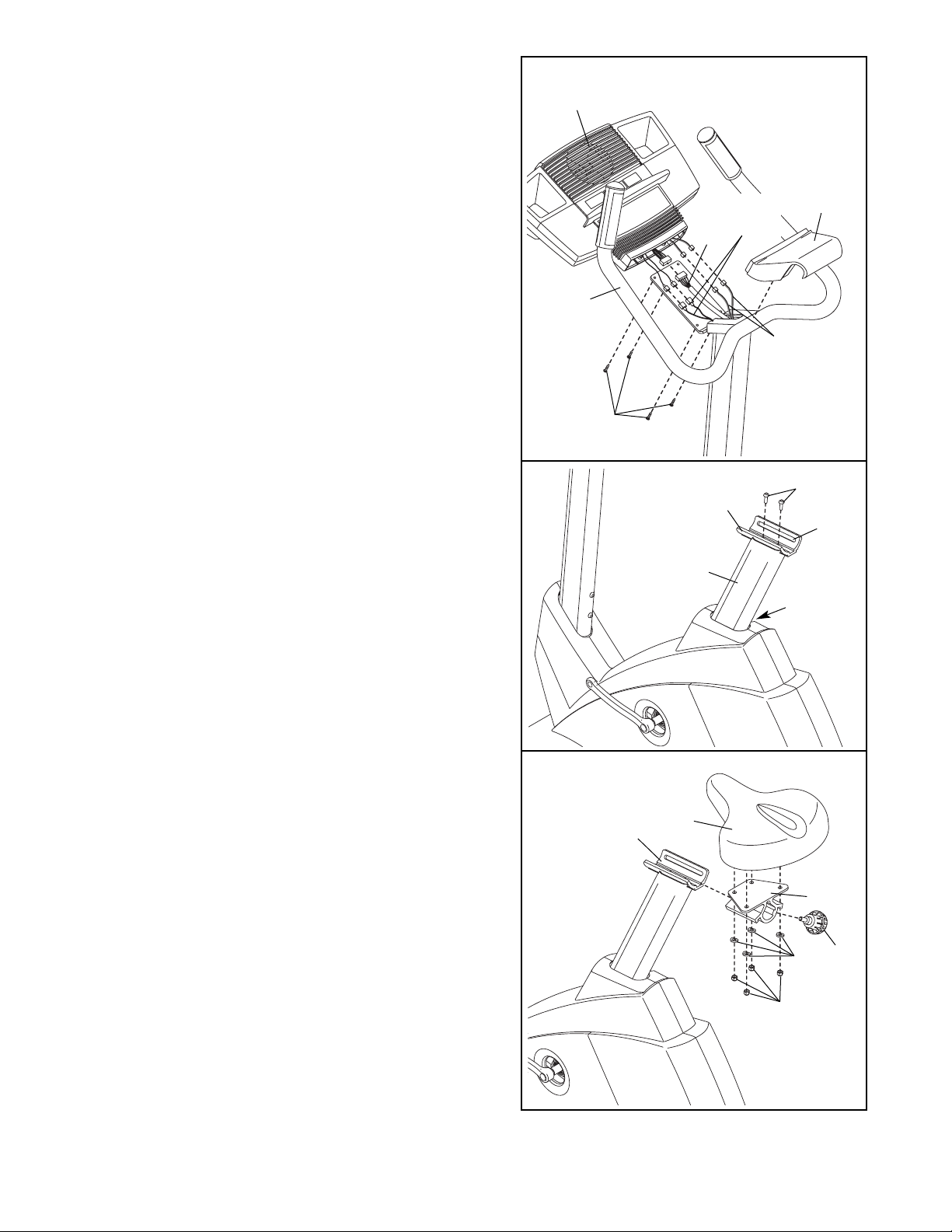
6. Turn the Seat Post Knob (20) counterclockwise two or
three turns to loosen it. Next, pull the Knob, raise the
Seat Post (8) a few inches, and then release the Knob.
Move the Seat Post up and down slightly until the
pin on the Knob snaps into one of the holes in the
Seat Post. Then, turn the Knob clockwise until it is
tight.
Attach the Seat Bracket (7) to the Seat Post (8) with
two M8 x 25mm Patch Screws (59). Make sure that
the Seat Bracket is oriented so the slot is on the
indicated side.
7. Attach the Seat (9) to the Seat Carriage (11) with four
M8 Nylon Locknuts (63) and four M8 Split Washers
(55). Note: The Nylon Locknuts and Split Washers
may be pre-attached to the underside of the Seat.
Slide the Seat Carriage (11) into the Seat Bracket (7).
Move the Seat (9) to the desired position. Insert the
Seat Knob (10) into the slot in the side of the Seat
Bracket, and tighten the Seat Knob into the Seat
Carriage.
8
59
Slot
7
20
5. Have another person hold the Console (4) near the
Handlebar (3).
Connect the Upper Wire Harness (42) to the wire harness on the Console (4). Locate the two ground wires
that are connected with a screw to the Handlebar (3).
Connect the two ground wires to the two smallest wires
on the Console. Next, locate the two pulse wires
extending from the Handlebar.
Connect each pulse
wire to the wire of the same color on the Console.
Snap the Handlebar Cover (5) onto the Handlebar (3).
Carefully insert all excess wires into the Console (4).
Attach the Console to the metal plate on the Handlebar
(3) with four M4 x 16mm Screws (57). Be careful to
avoid pinching the wires.
3
5
57
4
5
6
7
55
63
11
9
10
7
Do not pinch
the wires during
this step.
Pulse
Wires
Ground
Wires
42

8
9. Make sure that all parts are properly tightened before you use the exercise cycle. Note: After assembly is
completed, some extra parts may be left over. Place a mat beneath the exercise cycle to protect the floor.
8. Identify the Left Pedal (22), which is marked with an
“L.” Using an adjustable spanner, firmly tighten the
Left Pedal counterclockwise into the Left Crank Arm
(24). Tighten the Right Pedal (not shown) clockwise
into the Right Crank Arm. Important: Tighten both
Pedals as firmly as possible. After using the
exercise cycle for one week, retighten the
Pedals. For best performance, the Pedals must
be kept tightened.
Identify the Left Pedal Strap (25), which is marked
with an “L.” Attach the Left Pedal Strap to the Left
Pedal (22), and adjust it to the desired position.
Adjust the Right Pedal Strap (not shown) in the
same way.
8
22
24
25
9
HOW TO USE THE CHEST PULSE SENSOR
HOW TO PUT ON THE CHEST PULSE SENSOR
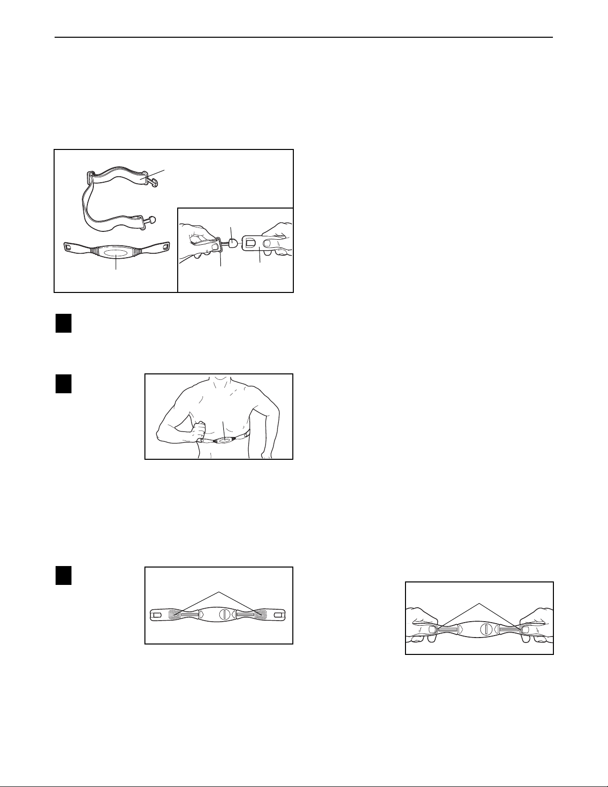
The chest pulse sensor consists of two components:
the chest strap and the sensor unit. Follow the steps
below to put on the chest pulse sensor.
See the inset drawing above. Insert the tab on
one end of the chest strap through one end of the
sensor unit. Press the end of the sensor unit
under the buckle on the chest strap.
Wrap the
chest pulse
sensor
around
your chest.
Attach the
free end of
the chest
strap to the
sensor unit as described above. Adjust the length
of the chest strap, if necessary. The chest pulse
sensor should be under your clothes, against
your skin, and as high under the pectoral muscles or breasts as is comfortable. Make sure that
the logo is right-side-up and facing forward.
Pull the
sensor unit
away from
your body
a few inches and
locate the
two electrode areas on the inner side. Using a saline
solution such as saliva or contact lens solution,
wet both electrode areas. Return the sensor unit
to a position against your chest.
CHEST PULSE SENSOR TROUBLESHOOTING
If the chest pulse sensor does not function properly, or if the displayed heart rate is excessively high
or low, try the troubleshooting steps below.
• Make sure that you are wearing the chest pulse sensor as described at the left. If the chest pulse sensor
does not function when positioned as described,
move it slightly lower or higher on your chest.
• Each time you use the chest pulse sensor, use
saline solution such as saliva or contact lens solution to wet the two electrode areas on the sensor
unit (see the drawing below). If heart rate readings
do not appear until you begin perspiring, re-wet the
electrode areas.
• Make sure that you are within arm’s length of the
console. For the console to display heart rate
readings, the user must be within arm’s length of
the console.
• If you wear the chest pulse sensor and hold the
handgrip pulse sensor at the same time, the console
may not display your heart rate accurately.
• The chest pulse sensor is designed to work with
people who have normal heart rhythms. Heart rate
reading problems may be caused by medical conditions such as premature ventricular contractions
(pvcs), tachycardia bursts, and arrhythmia.
• The operation of the chest pulse sensor can be
affected by magnetic interference caused by high
power lines or other sources. If it is suspected that
magnetic interference may be causing a problem,
try relocating your exercise equipment.
• If the chest pulse sensor still does not function properly, test the chest pulse sensor in the following way:
Hold the chest
pulse sensor
and place your
thumbs over
the electrode
areas as
shown. Next,
hold the chest
pulse sensor near the console. Whilst holding one
thumb stationary, begin tapping the other thumb
against the electrode area at a rate of about one tap
per second. Check the heart rate reading on the
console.
3
2
1
Chest Strap
Sensor Unit
Tab
Buckle
Electrode Areas
Sensor
Unit
Electrode Areas
Logo
 Loading...