

Panasonic SJMJ-55, SJMJ-55-GH Service manual
ORDER No.AD0211153C3
Portable MD Player
SJ-MJ55GH
Colour
(S)...................Silver Type
SPECIFICATIONS
Specifications

Audio
System:MiniDisc digital audio system
Beam source:Semiconductor laser
Wave length:780 nm
Sampling frequency:44.1 kHz
Coding:Adaptive Transform Acoustic
Coding (ATRAC/ ATRAC3)
No. of channels:2 (left and right, stereo)
1 (monaural)
Frequency response:20 Hz~20 kHz (+0 dB, -6dB)
Wow and flutter:Below measurable limit
General
Headphones:
Output level (approx.):3.0 mW+3.0 mW
Inpedance (approx.):32
Speakers (ceramic card type):
Output level (approx.):45 mW+45 mW
Inpedance (approx.):200 / 1kHz
Power supply
Rechargeable battery:DC 1.2V
(included rechargeable battery)
Battery:DC 1.5V (One LR6, AA, UM-3 battery)
Dimensions (WxHxD)
Cabinet dimensions:79.9x72.7x14.1 mm
incl.projecting parts:80.9x74.2x17.0 mm
Weights:96 g (with battery)
69 g (without battery)
Play time
[Approximate operating time in hours (in hold mode, at 25°C, on
a flat, stable surface)]
Battery type:Play time (Stereo/ LP2/ LP4)
Rechargeable:40 hours/ 53 hours/ 70 hours
Panasonic alkaline:63 hours/ 93 hours/ 121 hours
Both together:103 hours/ 148 hours/ 193 hours
[When the rechargeable battery (included) is fully recharged.]
AC adaptor and charger
AC adaptor input:AC220 V, 50/60 Hz, 5 VA
AC adaptor output and
DC 3.5 V, 0.5A
Charger input:
Charger output:DC 2V, 0.5 A
Recharging time:About 3.5 hours
Notes:
- The play time may be less depending on the operating
conditions.
- Specifications are subject to change without notice. Weight
and dimensions are approximate.
2002 Matsushita Electric Industrial Co., Ltd. All rights reserved.
Unauthorized copying and distribution is a violation of law.
1. Accessories
- Stereo earphones...................................................1 pc. /
(L0BAB0000174)
- Wired remote control..............................................1 pc. /
(N2QCBD000020)
- External battery case..............................................1 pc. /
(K3ZZ00200038)
- Nickel-metal hydride rechargeable battery.............1 pc. /
(RFKFFAZ01EM1)
- Soft case.................................................................1 pc. / (RFC0074-H)
- Speaker/Battery charger............................................1 pc. /
(L0EAAB000011)
- AC adaptor...............................................................1 pc. /
(N0JCBD000001)
2. Precaution of Laser Diode
3. Operating Instructions
4. Handling Precautions for MD Mechanism (Optical
pickup)
The laser diode in the MD mechanism (optical pickup) may break down due to potential
difference caused by static electricity of clothes or human body.
So, be careful of electrostatic breakdown during repair of the traverse deck (optical pickup).
4.1. Handling the MD mechanism (optical pickup)
1. The MD mechanism (optical pickup) is an extremely high-
precision construction and must not be subjected to impact,
excessive vibration, or other types of rough handling.
2. In order to prevent static electricity damage to the laser diode,
use a short pin or similar tool to short the optical pickup’s flexible
circuit boards after they have been disconnected from the main
circuit board. (as shown in Fig. 1 )
3. Handle the flexible circuit boards with care; excessive force could
cause them to be broken.
4. Do not turn the pre-set variable resistor (for adjustment of the
laser power); it has been adjusted at the factory.
(as shown in Fig. 2 )
Fig. 1

Fig. 2
4.2. Grounding for electrostatic breakdown prevention
1. Human body grounding
Use the anti-static wrist strap to discharge the static electricity
from your body. (as shown in Fig. 3 )
2. Work table grounding
Put a conductive material (sheet) or steel sheet on the area where
the traverse deck (optical pickup) is placed, and ground the sheet.
(as shown in Fig. 4 )
Caution
The static electricity of your clothes will not be grounded through
the wrist strap.
So, take care not to let your clothes touch the traverse deck (optical
pickup).
Fig. 3
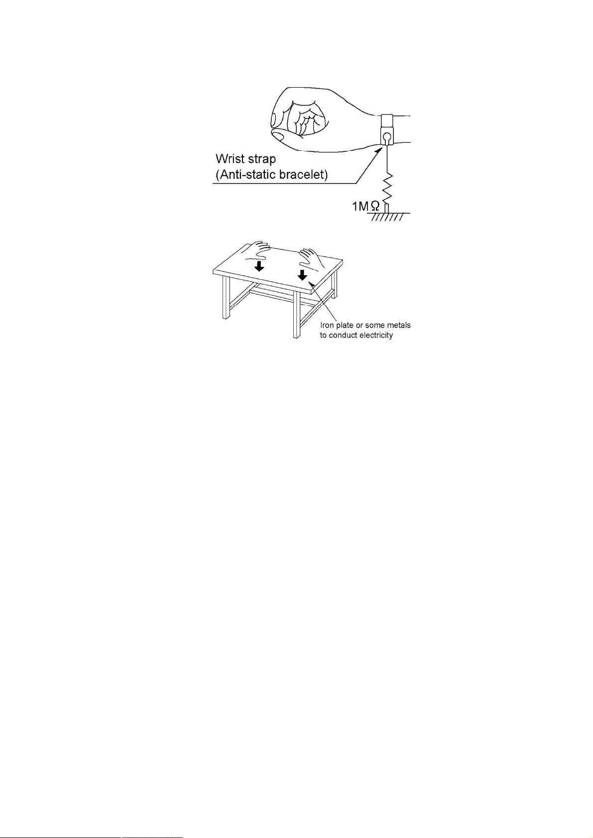
Fig. 4
5. Operation Checks and Component Replacement
Procedures
- This section describes procedures for checking the operation of
the major printed circuit boards and replacing the main
components.
- For reassembly after operation checks or replacement, reverse the
respective procedures. Special reassembly procedures are
described only when required.
- After replacing the main components (optical pickup or traverse
motor, etc.) of mechanism unit block, change to the adjust mode,
and then perform the adjustments (Laser power, off-set, ROM/
RAM).
5.1. Checking for the P.C.B.
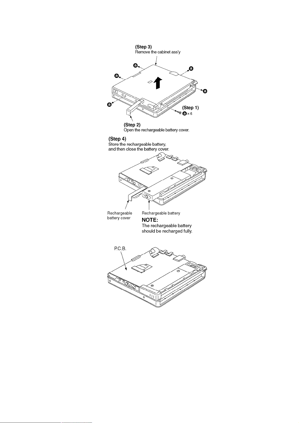
- Check the P.C.B. as shown below.
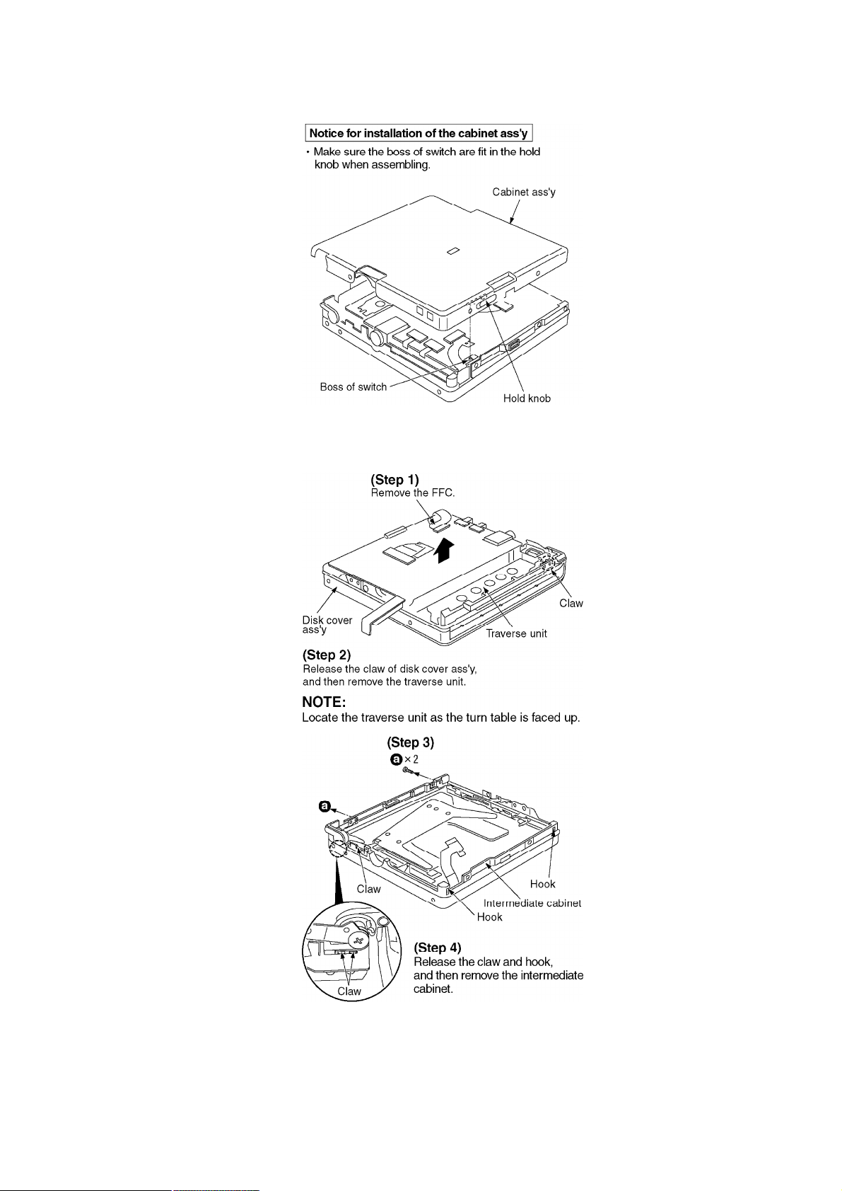
5.2. Replacement for the intermediate cabinet
- Follow the (Step1)-(Step3) of item 5.1.
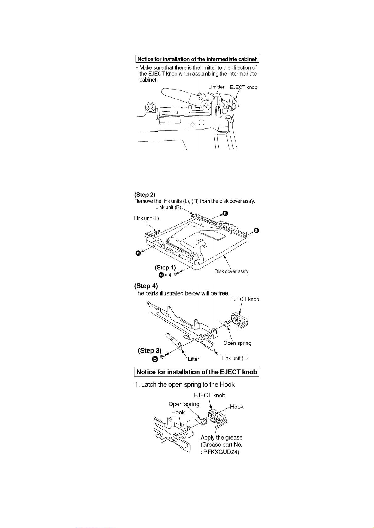
5.3. Replacement for the disk cover ass’y and the link units (L), (R)
- Follow the (Step1)-(Step3) of item 5.1.
- Follow the (Step1)-(Step4) of item 5.2.
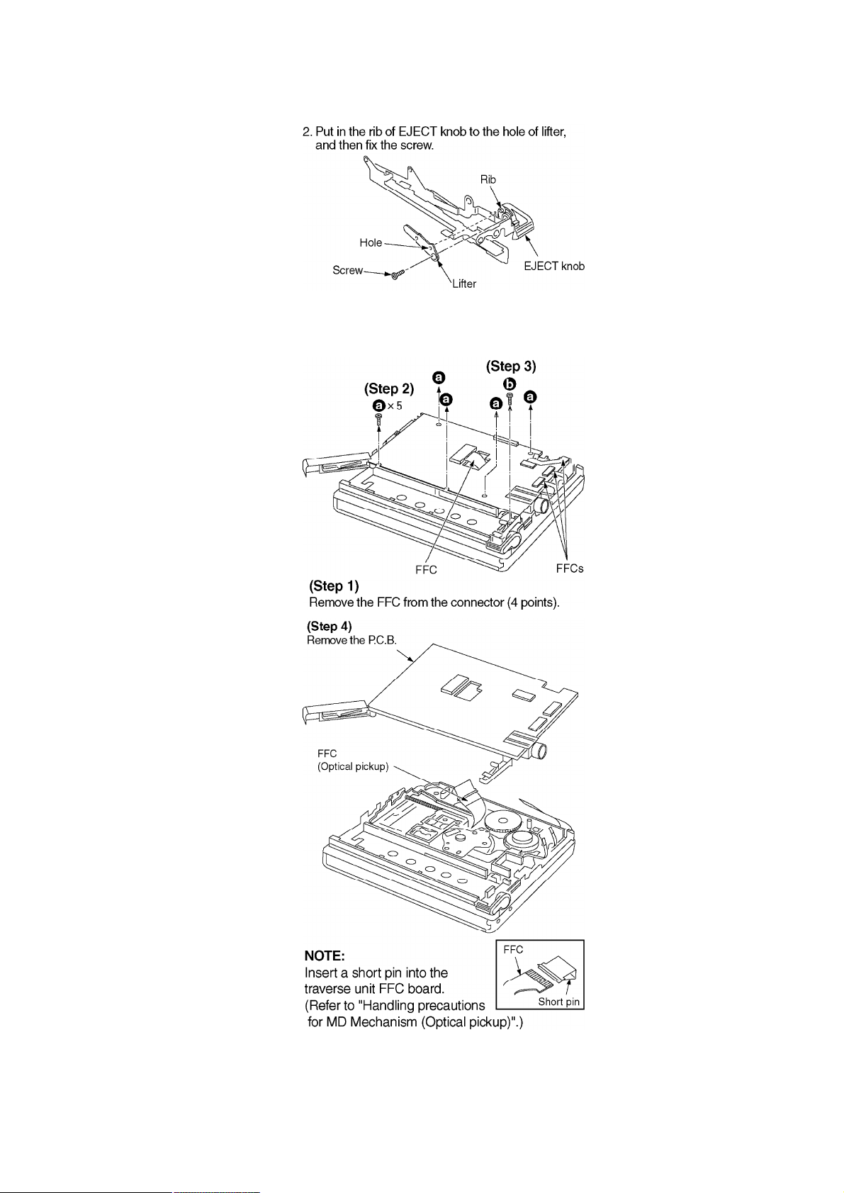
5.4. Replacement for the traverse motor
- Follow the (Step1)-(Step3) of item 5.1.
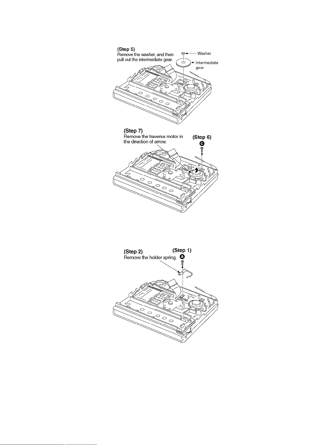
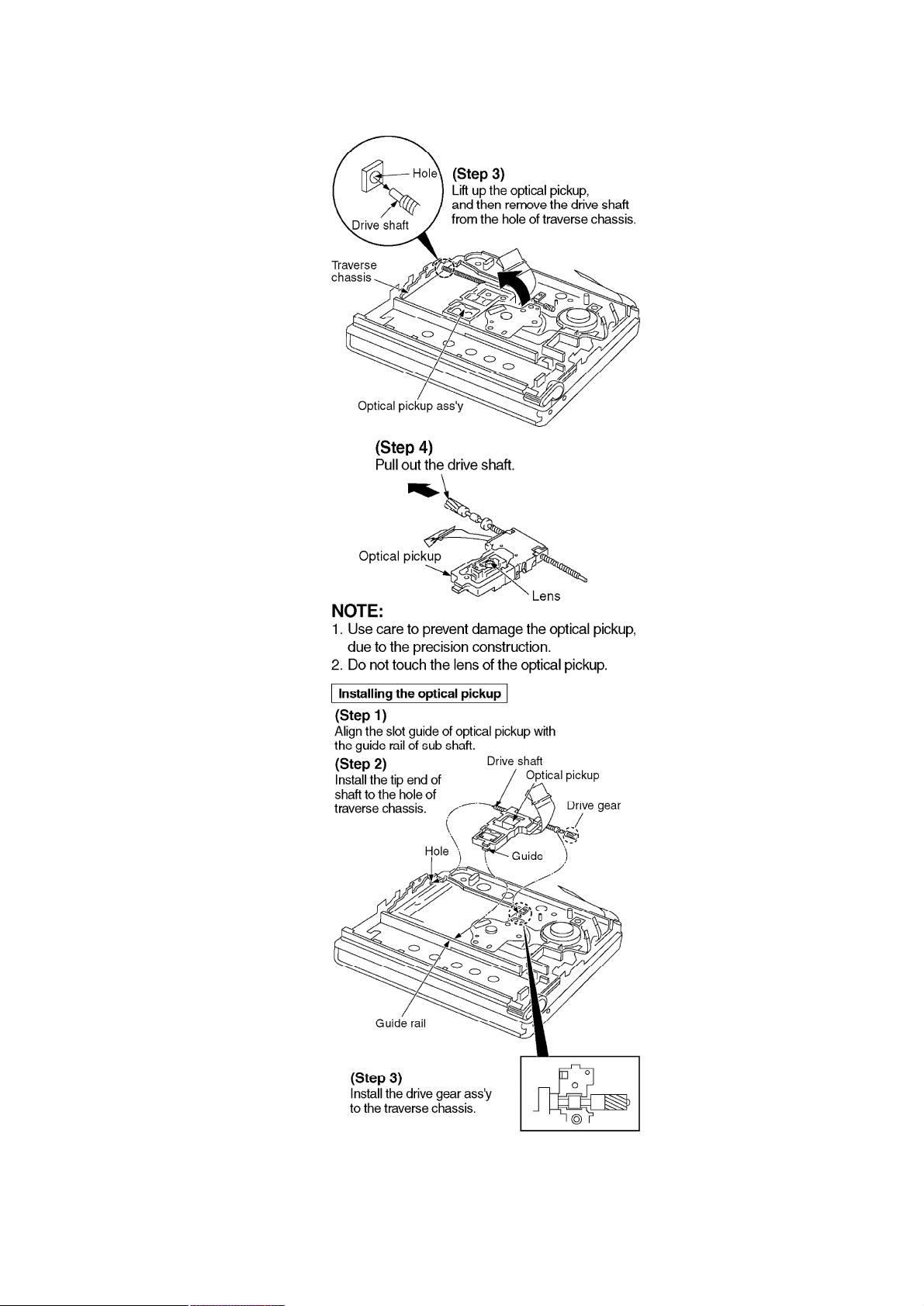
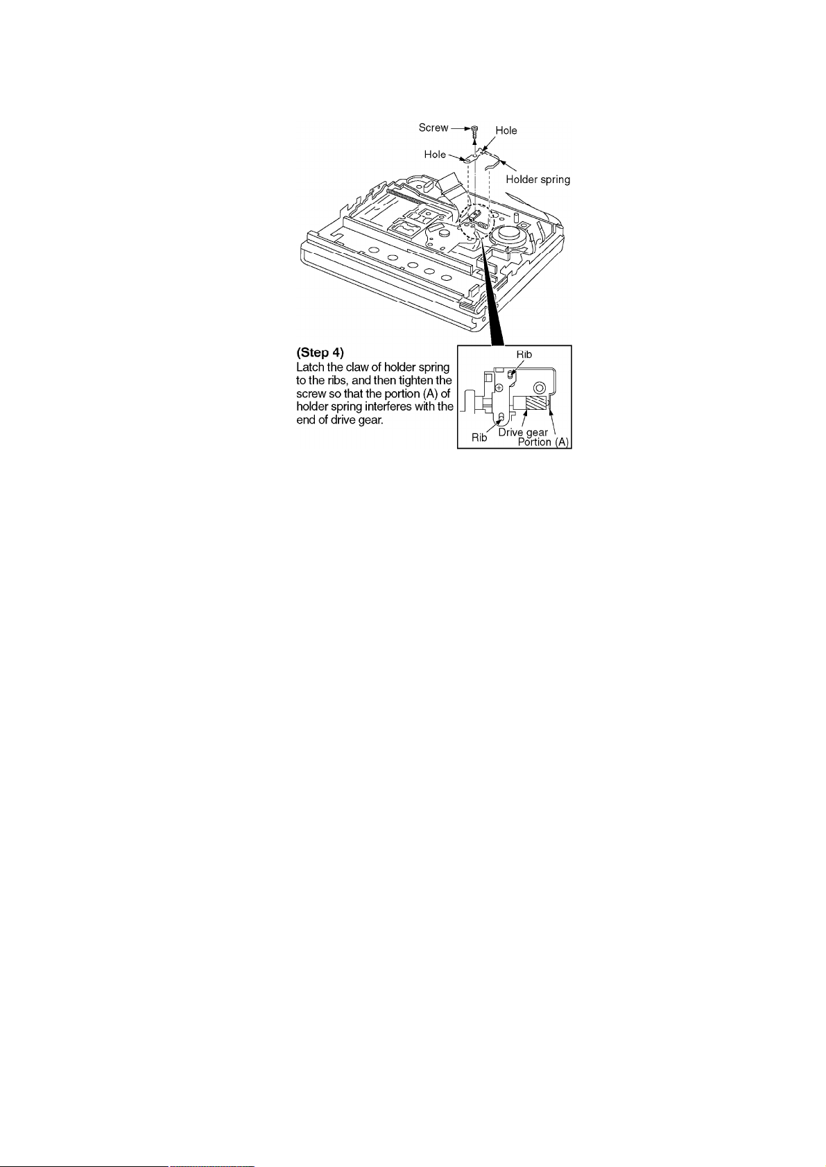
5.5. Replacement for the optical pickup
- Follow the (Step1)-(Step3) of item 5.1.
- Follow the (Step1)-(Step5) of item 5.4.
6. Measurements and Adjustments
Note:
After replacing the main components (optical pickup, traverse motor, IC201, IC202 or P.C.B.
ass’y, etc.) of mechanism unit block, change to the adjust mode, and then perform the “Laser
power adjustment”, “Off-setautomatic adjustment” and “Playback-only disc/magneto-optical
disc automatic adjustment”.
6.1. Instruments to prepare
1. Playback-only disc (Test disc RFKV0006)
2. Commercially available recordable disc (fully recorded with
music) (magneto-optical disc)
3. Laser power meter (LE8010 or compatible meter)
4. Remote controller (Parts No: N2QCBD000020) [or Remote
controller of SJ-MJ88 etc. (Parts No: RFEV025P-SM)]
6.2. Laser power adjustment, Off-set automatic adjustment, Playback
-only disc/magneto-optical disc automatic adjustment magnet
6.2.1. Enter the adjustment mode
Note:
For use of MD cartridge type laser power meter, disassemble this unit into the state of only the
mechanism unit before perform the laser power adjustment (as for the method of disassembly,
refer to “5.2. Replacement for the intermediatecabinet”).

1. Set the battery and connect the remote controller. (The position of
the HOLD switch of remote controller is “OFF”.)
2. Turn off the power, and switch main unit’s HOLD switch off.
3. Press the VOL+( ), VOL-( ), ( ), and ( )keys on the
remote controller within two seconds. (asshown in Fig. 5 )
Fig. 5
4. When the adjustment mode is activated, “T0E ” will be displayed
on the LCD of remote controller. After “T0E ” is displayed, select
the desired adjustment item with the button or button of
the remote controller. (If it is not displayed, perform the
procedures written above again.)
*In the display of T0E ~ TFE shown above, you must adjust T0E , T1E , T2E and T3E . You must
perform the adjustment by observing the order T0E T1E T2E T3E .
Note:
If it is going to perform “T2E” and “T3E”, without performing “T1E”, it will be displayed as “NG”.
If it is going to perform “T3E” when “T2E” is “NG”, it will be displayed as “NG”.

6.2.2. Laser Power Adjustment
Adjust each laser power: read power for reading (play).
6.2.2.1. Set the Unit to the Adjustment Mode
Cautions
About handling the optical pickup and the magnetic head.
- The optical pickup is structured precisely; therefore, it is very
fragile. Be careful not to touch it with the edge of the laser power
meter. Do not touch the lens.
- The sensor of the laser power meter is a very fine part. Be careful
not to touch it to the optical pickup lens.
- The focus point of the laser reaches to 356°F. Therefore, avoid
adjusting using laser power for a long time because the sensor of
the laser power meter may be burned.
- Do not set the unit to the laser power adjustment mode with the
MD loaded. Doing so may result in damage to the MD.
- Laser diode in the optical pickup may be destroyed by the static
electricity generated in your clothes or body. Be especially careful
with the static electricity.
6.2.2.2. Adjustment Procedure
1. Have “T0**” indicated on display, and move the optical pickup to
the most inside (only when a MD cartridge type laser power meter
is used).
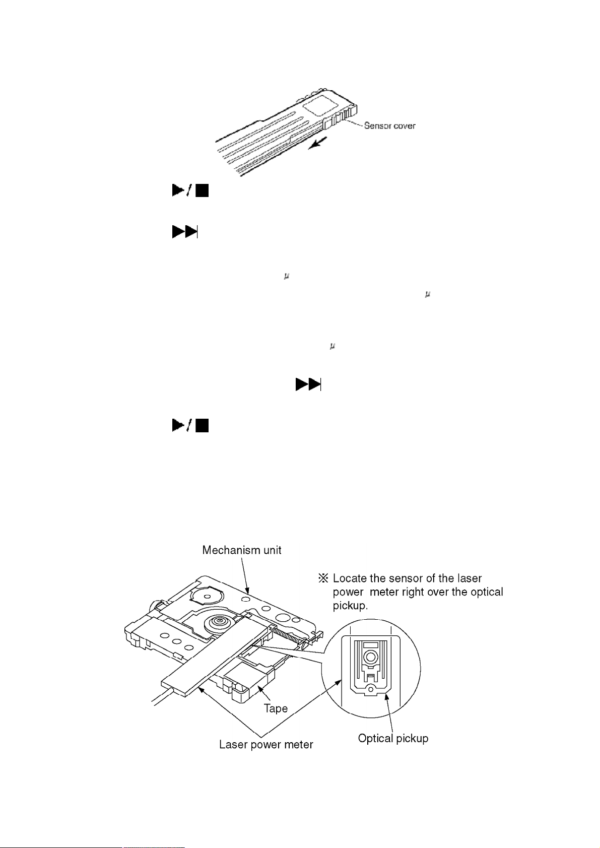
2. Set the laser power meter.
[For use of stick type laser power meter.]
2-1 Uncover the laser power meter (as shown in Fig. 6 ).
2-2 Locate the sensor of the laser power meter right over above
the optical pickup (horizontally at a level of the disc position).
(as shown in Fig. 7 )
[For use of MD cartridge type laser power meter.]
2-1 Open the shutter of the laser power meter. (as shown in Fig. 9 )
2-2 Set the laser power meter. (as shown in Fig. 8 )
Fig. 6
3. Press the key of the remote controller (“T0E ” changes to
“LD ” of the LCD).
4. Press the key of the remote controller (“LD ” changes to “LP ”
of the LCD).
5. Set the laser power at 600 W±10% by using VOL+ and VOL- key
of the remote controller. / [Specified range: 600 W±10%]
Caution:
Proceeding on to the subsequent adjustment procedure with the
read power exceeding “over 660 W” will result in damage to the
optical pickup.
6. Set the laser power with the key of the remote controller (“LP
” changes to “LDOK ” in the LCD).
7. Press the key of the remote controller (“LDOK ” changes to
“T0E ” on the LDC.
8. Remove the laser power meter. Laser power adjustment is
finished.
<Stick type>
Fig. 7
 Loading...