

Panasonic SJHD-515, SJHD-515 Service manual
AD0003058C2
Mini Disc Deck
SPECIFICATIONS
SJ-HD515
Mechanism Unit: MR3A
Colour
(S)..........Silver Type
Area
(E)..........Europe.
1

2000 Matsushita Electric Industrial Co., Ltd. All rights reserved.
Unauthorized copying and distribution is a violation of law.
1. Note
Refer to the service manual for Model No. SE-HD515MD (ORDER No. AD0003056C2) for
information on Accessories and Packaging.
2. Blue LED
- The blue LED mounted to each sides of front panel is very
sensitive to static electricity. When handling the LED base plate,
be very careful about it.
- Do not replace the blue LED by itself because it may be subject to
electrostatic breakdown or deterioration in quality. When
replacing the LED base plate, be sure to replace L and R sides
simultaneously to adjust the brightness. For configuration at the
time of supply of replacement parts, refer to Printed Circuit Board
Diagram.
3. Before Repair
This equipment (SJ-HD515), which is a component of the system, is supplied with power from
the Amplifier (SE-HD515MD) through the Tuner (ST-HD515MD). When repairing this equipment
or checking operation of the system, be sure to connect to the amplifier and tuner with it.
This equipment, even in the state of it as a single equipment, permits power supply and
operation check. When operating it as a single equipment without the amplifier and tuner, refer
to the To Supply Power Source and Signal Check .
4. Handling Precautions for MD Unit
The laser diode in the MD unit (optical pickup) may break down due to potential difference
2
caused by static electricity of clothes or human body. So be careful of electrostatic breakdown
during repair of the MD unit (optical pickup).
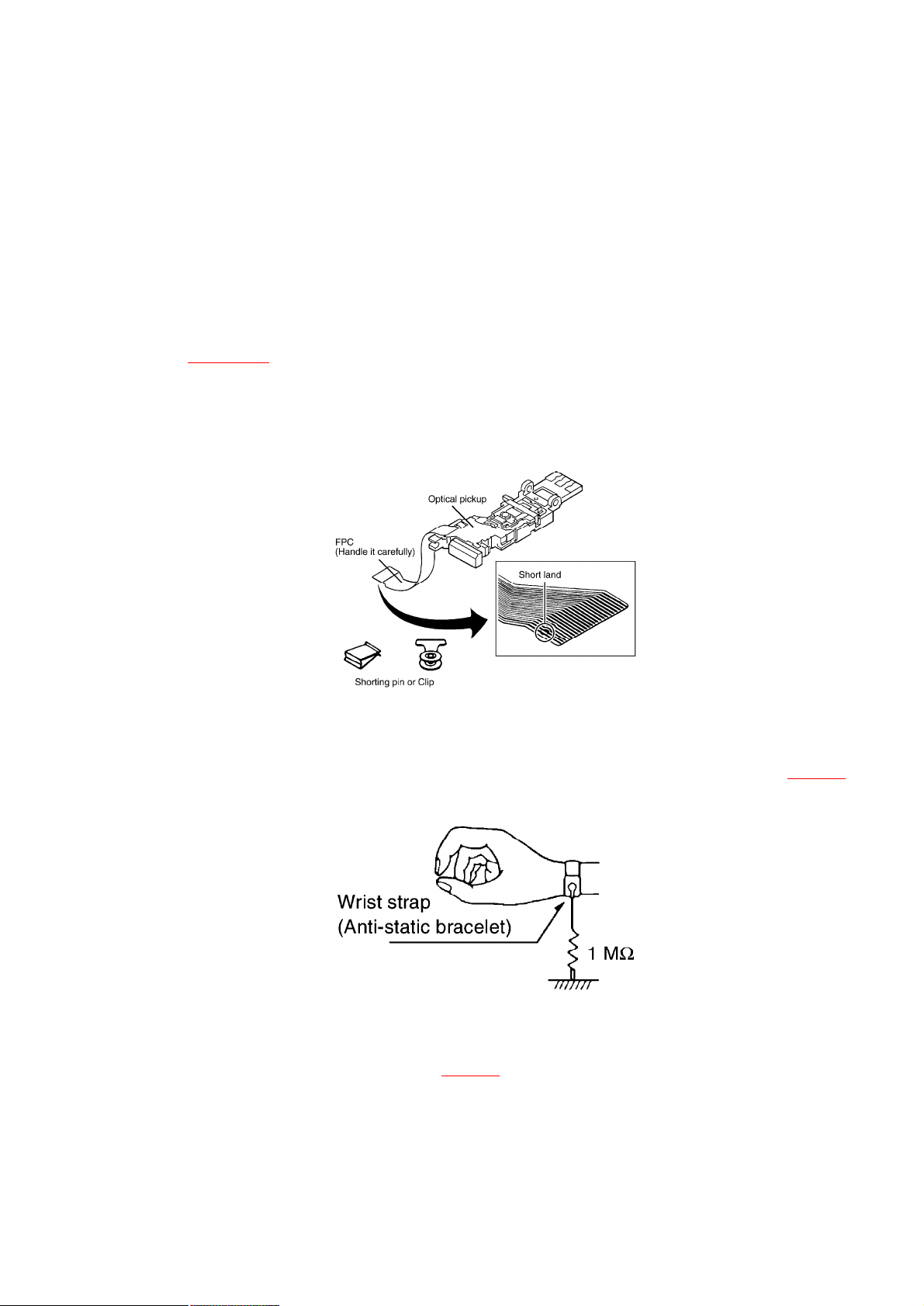
4.1. Handling of MD Unit (optical pickup)
1. Do not subject the MD unit (optical pickup) to static electricity as
it is extremely sensitive to electrical shock.
2. To protect the breakdown of the laser diode, an anti-static
shorting pin is inserted into the flexible board (FPC board). Refer
to Fig. 4-1.
3. Take care not to apply excessive stress to the flexible board (FPC
board).
Fig. 4-1.
4.2. Grounding for electrostatic breakdown prevention
4.2.1. Human body grounding
Use the anti-static wrist strap to discharge the static electricity from your body. Refer to Fig. 4-2.
Fig. 4-2.
4.2.2. Work table grounding
Put a conductive material (sheet) or steel sheet on the area where the MD unit (optical pickup)
is placed, and ground the sheet. Refer to Fig. 4-3.
Fig. 4-3.
3

Caution:
The static electricity of your clothes will not be grounded through
the wrist strap.
So take care not to let your clothes touch the MD unit (optical
pickup).
5. Precaution of Laser Diode
6. Location of Controls
7. Operation Checks and Component Replacement /
Procedures
- This section describes procedures for checking the operation of
the major printed circuit boards and replacing the main
4
components.
- For reassembly after operation checks or replacement, reverse the
respective procedures. Special reassembly procedures are
described only when required.
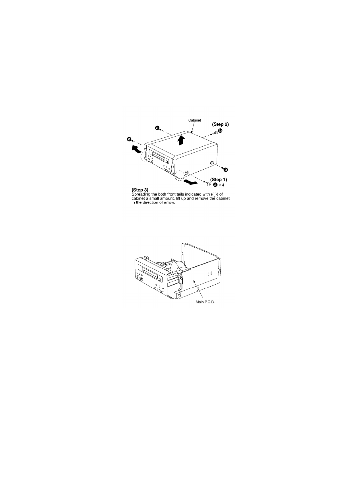
7.1. Checking for the main P.C.B.
- Check the main P.C.B. as shown below.
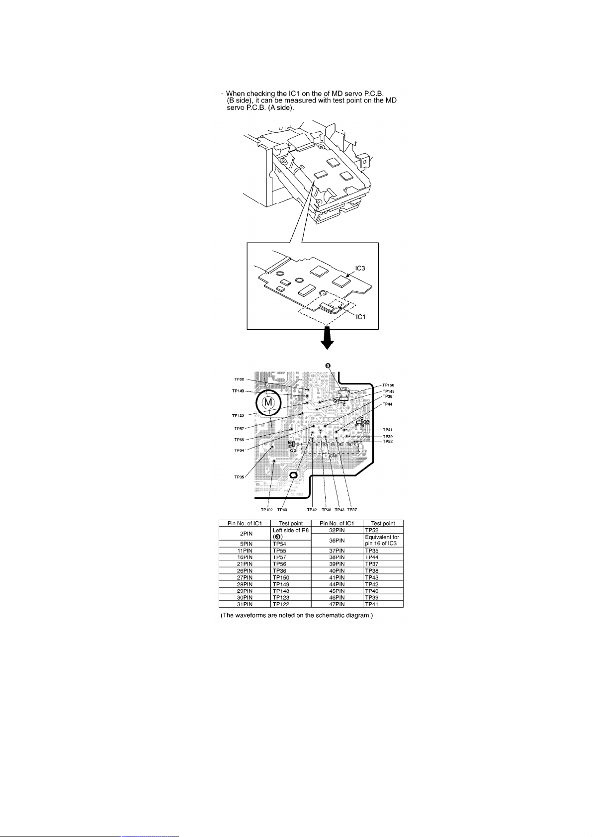
7.2. Checking for the MD servo P.C.B.
7.2.1. Checking for the MD servo P.C.B. (A side)
- Follow the (Step 1) - (Step 3) of item 7.1.
5

- Check the MD servo P.C.B. (A side) as shown below.
7.2.2. Checking for the MD servo P.C.B. (B side)
6
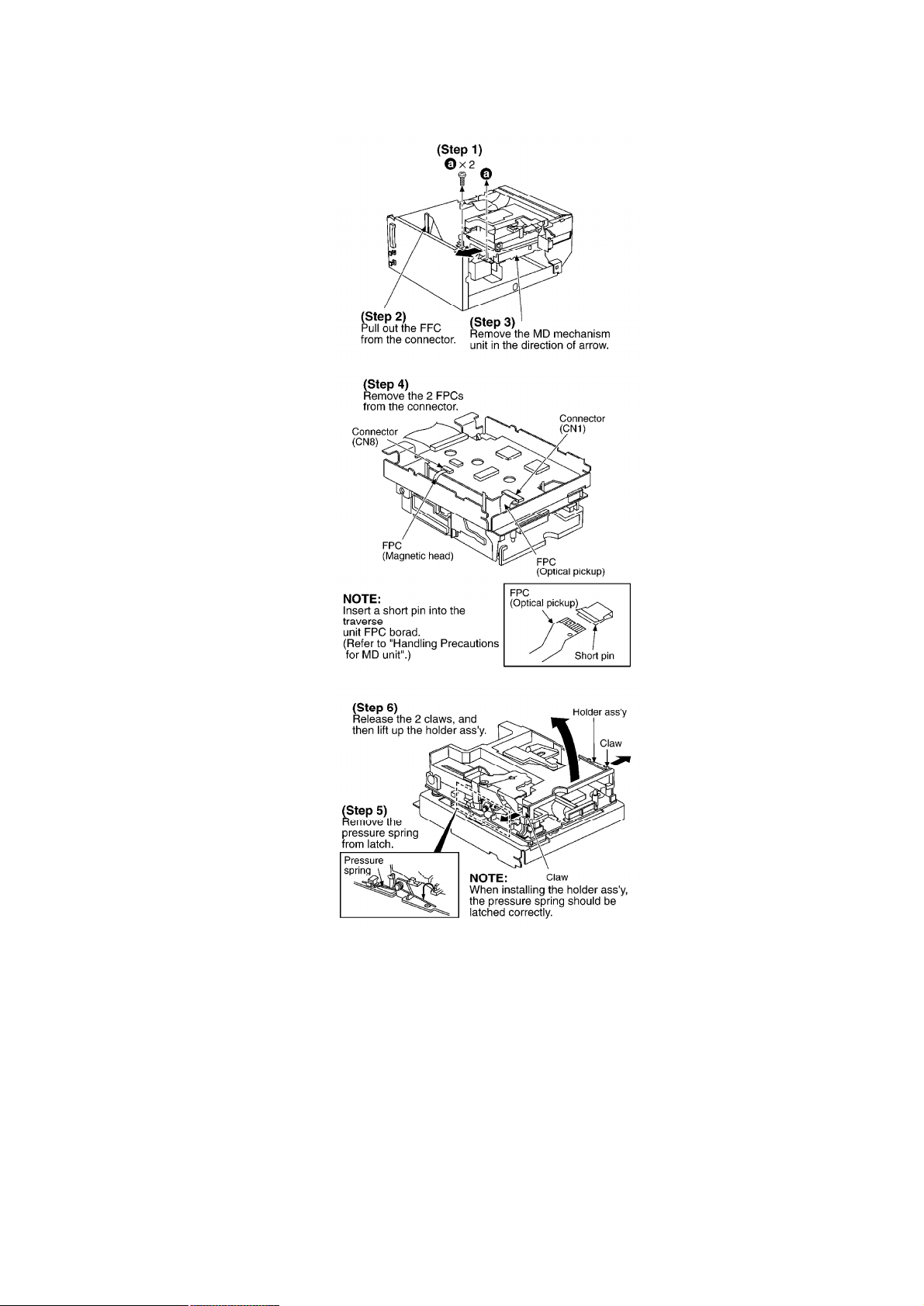
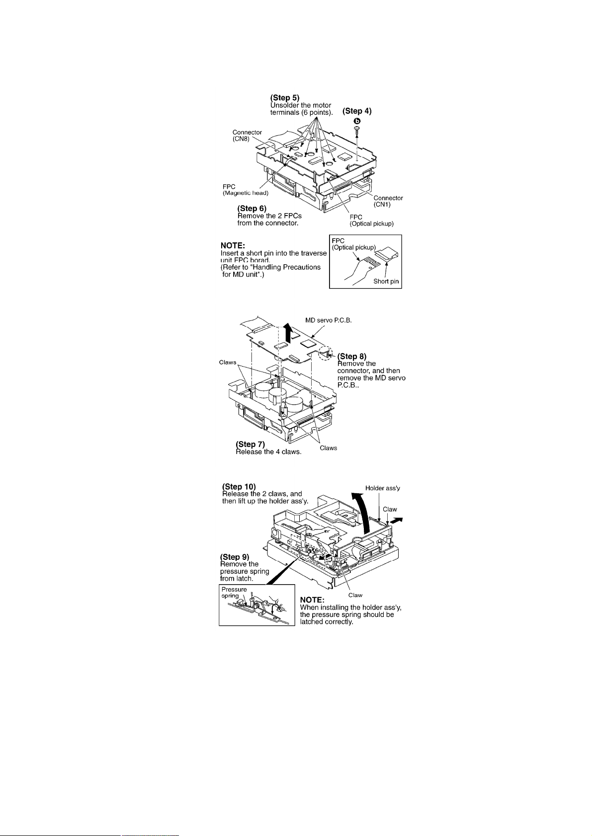
7.3. Replacement for the magnetic head and optical pickup
- Follow the (Step 1) - (Step 3) of item 7.1.
789

10

7.4. Replacement for the belt and loading motor ass’y
- Follow the (Step 1) - (Step 3) of item 7.1.
11
12

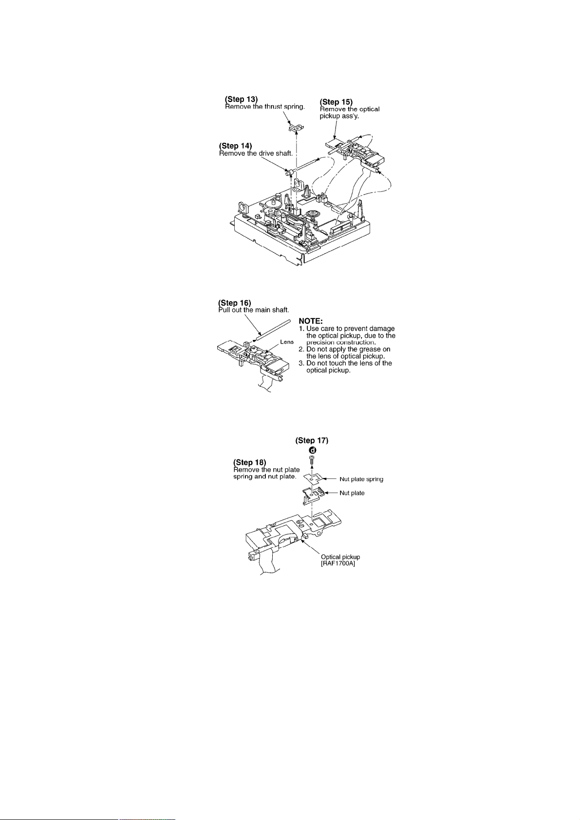
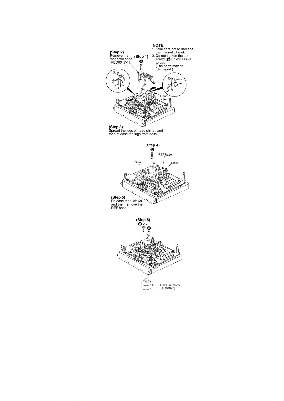
7.5. Replacement for the traverse motor ass’y
- Follow the (Step 1) - (Step 3) of item 7.1.
- Follow the (Step 1) - (Step 11) of item 7.3.
13
14
 Loading...