

Page 1
SUNX Limited MJE-SFBHC No.6085-02
1
Page 2

Thank you for purchasing SUNX’s Handy Controller SFB-HC (Ver.2) (hereinafter called ‘this device’)
exclusive for SF4B series.
Please read both the instruction manual of this manual and SF4B series or SF-C14EX carefully and
thoroughly for the correct and optimum use of this product.
Kindly keep this manual in a convenient place for quick reference.
.
NOTICE
1) All the contents of this instruction manual are the copyright of the publishers, and may not be reproduced
(even extracts) in any form by any electronic or mechanical means (including photocopying, recording, or
information storage and retrieval) without permission in writing from the publisher.
2) The contents of this instruction manual may be changed without prior notice for further improvement of
the product.
3) A part of / all of this instruction manual or the software may not be copied without permission from the
publisher.
4) Though we have carefully drawn up the contents of this instruction manual, if there are any aspects
that are not clear, or any error that you may notice, please contact our local SUNX office or the
nearest distributor.
5) We shall not be responsible for any consequences of use regardless of the descriptions above.
2
SUNX Limited MJE-SFBHC No.6085-02
Page 3

Contents
CHAPTER 1 INTRODUCTION ························································································· 4
1-1 Before Using This Product···································································································· 4
1-2 Safety Precautions ················································································································ 4
CHAPTER 2 GENERAL ··································································································· 6
2-1 Features·································································································································· 6
2-2 Part Descriptions ··················································································································· 6
2-3 Connecting / Setting Procedures ························································································· 7
2-3-1 When Using with Light Curtain SF4B Series Only ······················································· 7
2-3-2 When Using in Combination with Application Expansion Unit SF-C14EX···················· 9
CHAPTER 3 FUNCTIONS································································································ 11
3-1 Functional Descriptions <When Using with Light Curtain SF4B Series Only>················· 11
3-1-1 Fixed Blanking Function······························································································ 11
3-1-2 Floating Blanking Function·························································································· 12
3-1-3 Auxiliary Output Switching Function ············································································ 13
3-1-4 Emission Intensity Control Function ············································································ 13
3-1-5 Copy Function············································································································· 14
3-1-6 Muting Setting Changing Function ·············································································· 14
3-1-7 Interlock Setting Changing Function············································································ 14
3-1-8 External Device Monitor Setting Changing Function ··················································· 15
3-1-9 Protect Function·········································································································· 15
3-1-10 Initialization Function································································································· 15
3-1-11 Setting Contents Monitoring Function········································································ 15
3-2 Functional Descriptions
<When Using in Combination with Application Expansion Unit SF-C14EX>···················· 16
3-2-1 Fixed Blanking Function······························································································ 16
3-2-2 Floating Blanking Function·························································································· 17
3-2-3 Auxiliary Output Switching Function ············································································ 18
3-2-4 Emission Intensity Control Function ············································································ 18
3-2-5 Copy Function············································································································· 19
3-2-6 Muting Setting Changing Function ·············································································· 19
3-2-7 Interlock Setting Changing Function············································································ 19
3-2-8 External Device Monitor Setting Changing Function ··················································· 19
3-2-9 Protect Function·········································································································· 20
3-2-10 Initialization Function································································································· 20
3-2-11 Setting Contents Monitoring Function········································································ 20
3-3 Function Setting (Operation Procedure) ············································································ 21
3-3-1 Fixed Blanking Function······························································································ 24
3-3-2 Floating Blanking Function·························································································· 25
3-3-3 Auxiliary Output Switching Function ············································································ 26
3-3-4 Emission Intensity Control Function ············································································ 27
3-3-5 Copy Function············································································································· 28
3-3-6 Muting Setting Changing Function ·············································································· 29
3-3-7 Interlock Setting Changing Function············································································ 30
3-3-8 External Device Monitor Setting Changing Function ··················································· 31
3-3-9 Protect Function·········································································································· 32
3-3-10 Initialization Function································································································· 33
3-3-11 Setting Contents Monitoring Function········································································ 34
CHAPTER 4 TROUBLE SHOOTING ··············································································· 35
CHAPTER 5 SPECIFICATIONS / DIMENSIONS····························································· 36
5-1 Specifications ························································································································ 36
5-2 Dimensions ···························································································································· 36
SUNX Limited MJE-SFBHC No.6085-02
3
Page 4
CHAPTER 1 INTRODUCTION
1-1 Before Using This Product
This manual has been written for the following personnel who have undergone suitable training and have
knowledge of light curtains, as well as, safety systems and standards (ANSI, etc.).
㨯who are responsible for the introduction of this device
㨯who design a system using this device
㨯who install and connect this device
㨯who manage and operate a plant using this device
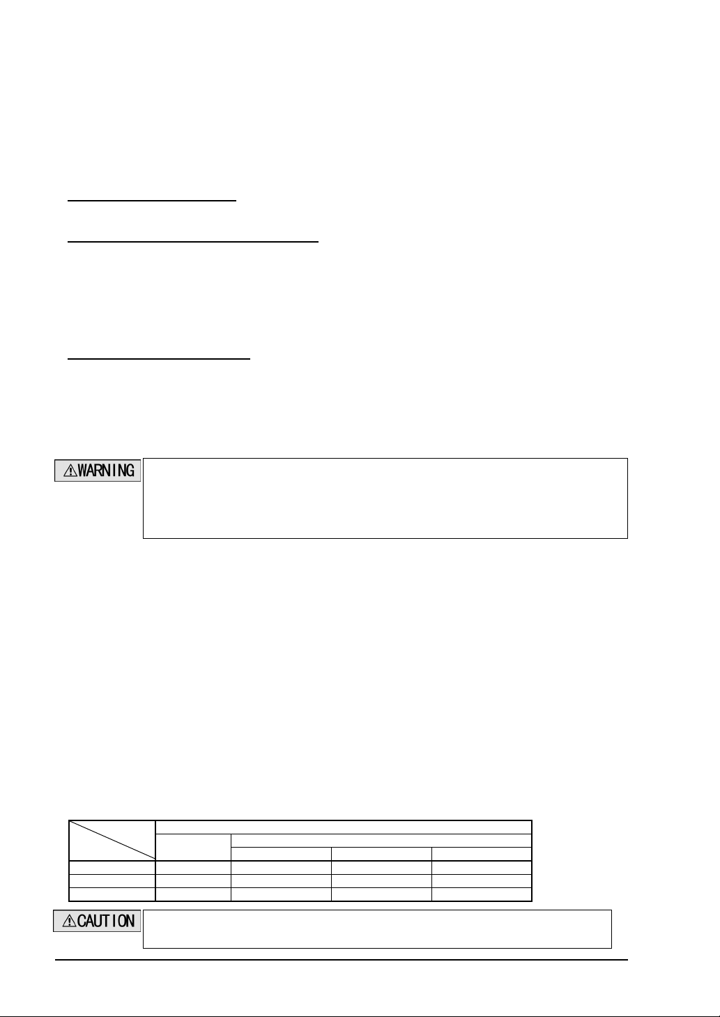
1-2 Safety Precautions
Attention marks
This instruction manual employs the following attention marks
on the degree of the danger to call operator’s attention to each particular action. Read the following
explanation of these marks thoroughly and observe these notices without fail.
Besides, the attention mark is prepared for the helpful information, detail instruction related to each part,
and reference item or page.
If you ignore the advice with this mark, death or serious injury could result.
If you ignore the advice with this mark, injury or material damage could result.
The supplementary content is described with this mark.
, depending
The related content is described with this mark.
4
SUNX Limited MJE-SFBHC No.6085-02
Page 5

x User in charge
㨯 The user in charge has responsible to indicate the person to take the training required for the safety system,
using method, installation, operation, and maintenance.
㨯 This device is used and managed by the specialist, never use this device by other operator.
x Specialist
㨯 A person who is appropriately educated, has widespread knowledge and experience, and can solve
various problems which may arise during work.
x Operator
㨯 The operator should read this instruction manual thoroughly, understand its contents, and perform
operations following the procedures described in this manual, for the correct operation of this device.
㨯 In case this device does not perform properly, the operator should report this to the person in charge and
stop the machine operation immediately. The machine must not be operated until correct performance of
this device has been confirmed.
x Fixed blanking function, floating blanking function
㨯 With the fixed blanking function, this device prevents the person or object from entering into the dangerous
parts through the invalid detecting area. However, even though this device can prevent the interference of
the person or object into the invalid detecting area with the fixed blanking function, there might exist the
more space between the sensor and already-existence object. Therefore, set the protecting structure so as
not to exist any space in the dangerous detecting area. Detecting human body in the detecting area could
result in serious injury or death.
㨯 With the floating blanking function, this device changes the size of the min. detectable object of the light
curtain that is pre-set the function. When setting or changing the function, calculate and measure the safety
distance again, and check that the device has the wider space than the safety distance between the
dangerous zone and the detecting are of the light curtain.
If the sufficient distance is not maintained, the machine will not stop before its dangerous parts are reached,
which can result in serious injury or death.
㨯 Set and change the function of the device following the relative laws, regulation, and standard without fail.
x Environment
㨯 Do not use a mobile phone or a radio phone near this product.
㨯 Do not install this device in the following environments.
1) Areas with high humidity where condensation is likely to occur
2) Areas exposed to corrosive or explosive gases
3) Areas exposed to vibration or shock of levels higher than that specified
4) Areas exposed to contact with water
5) Areas exposed to too much steam or dust
x Wiring
㨯 Be sure to carry out the wiring in the power supply off condition.
㨯 All electrical wiring should conform to the regional electrical regulations and laws. The wiring should be
done by engineer(s) having the special electrical knowledge.
㨯 Do not run the sensor cable together with high-voltage lines or power lines or put them together in the
same raceway.
x Maintenance
㨯 Clean this device with a clean cloth. Do not use any volatile chemicals.
x Other
㨯 Never reassemble or remodel this product.
SUNX Limited MJE-SFBHC No.6085-02
5
Page 6
CHAPTER 2 GENERAL
This chapter gives the system construction, part description, etc. of this device.
2-1 Features
This device is the handy controller for setting each function of the light curtain SF4B series and the
application expansion unit SF-C14EX.
Besides, this handy controller performs the checking and copying the setting contents of the function, and
protection of writing.
<Functions>
Fixed blanking function
Floating blanking function
Auxiliary output switching function
Emission intensity control function
Copy func tion
Muting setting changing function
Interlock setting changing function
External device monitor setting changing function
Protect function
Initialization function
Setting contents monitoring function
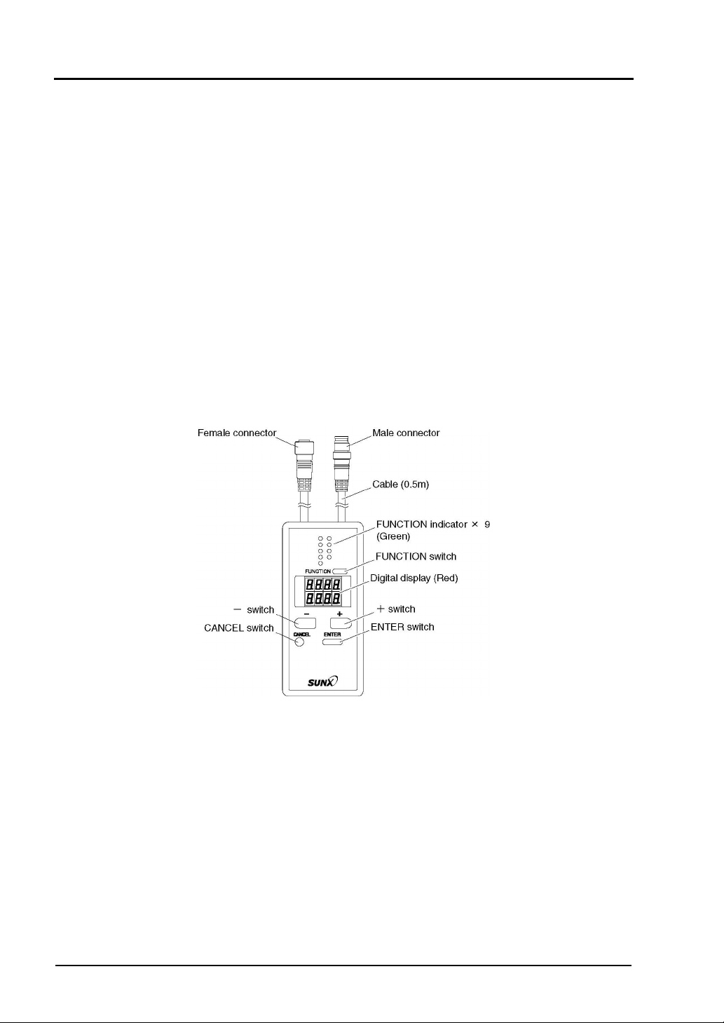
2-2 Part Descriptions
6
SUNX Limited MJE-SFBHC No.6085-02
Page 7
2-3 Connecting / Setting Procedures
This section describes the connecting / setting procedures for both this device and SF4B series or
SF-C14EX.
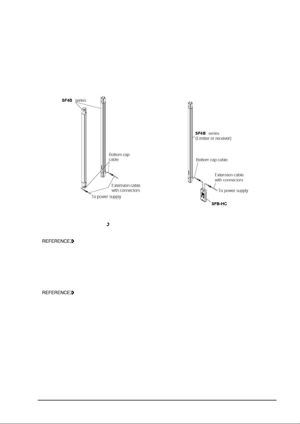
2-3-1 When Using with Light Curtain SF4B Series Only
<When using the 8-core cable>
Ԙ Set the SF4B series, and check that the SF4B
series works properly. For details of mounting
method of SF4B series, refer to the ‘SF4B
Instruction manual’.
ԙ Turn off the power, and disconnect the
extension cable with connectors connected to
SF4B series, and then connect this device
between SF4B series and the extension cable
with connectors.
Ԛ Turn on the power, and set the function with this device.
After the power of this device is on, approx. 30 sec. will be taken for data transmission with SF4B series.
While data transmission, ’
‘ lights up in revolving.
=The control output (OSSD 1, OSSD 2) of SF4B series is set to ‘OFF’ while this device has been connected.?
Refer to ‘3-1 Functional Descriptions <When Using with Light Curtain SF4B Series
Only>
’ for the detail of the functions, and refer to ‘3-3 Function Setting (Operation
Procedure)’ for the detail of the setting procedure of the functions respectively.
ԛ Turn off the power, and remove this device.
Ԝ Connect both SF4B series and the connecting cable, and return the device to the state described in
procedure Ԙ.
ԝ Check that the SF4B series works as set at the procedure Ԛ. Then, inspect the SF4B series.
Refer to ‘Chapter 3 Maintenance’ of the SF4B series instruction manual for the detail of
the inspection of the SF4B series.
SUNX Limited MJE-SFBHC No.6085-02
7
Page 8
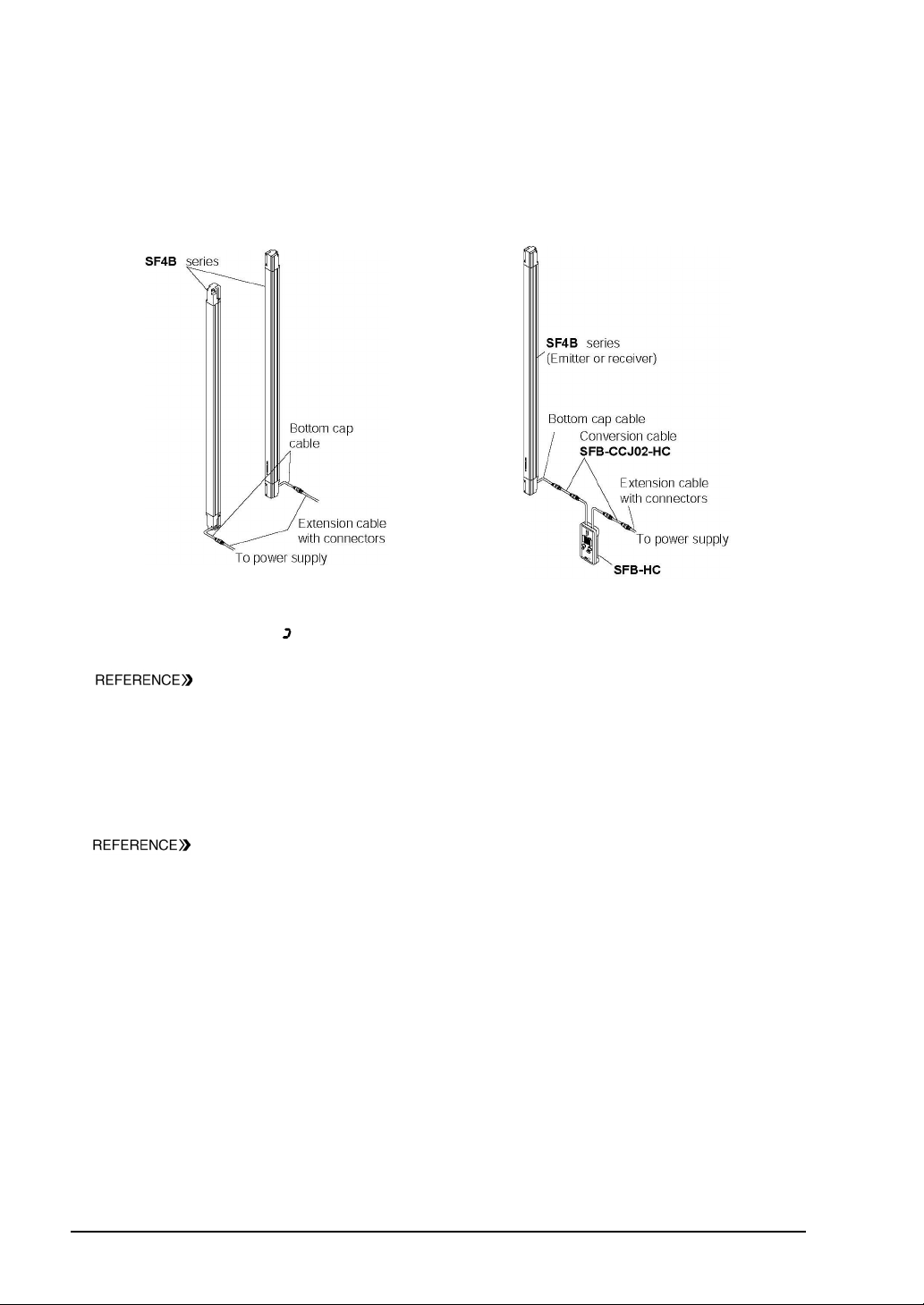
<When using the 12-core cable>
When the connection cable for the muting function, the conversion cable (SFB-CCJ02-HC) (optional) is
used.
Ԙ Set the SF4B series, and check that the SF4B
series works properly. For details of mounting
method of SF4B series, refer to the ‘SF4B
Instruction manual’.
ԙTurn off the power, and disconnect the extension
cable with connectors connected to SF4B series,
and then connect this device and SFB-CCJ02-HC
between the sensor (emitter or receiver) and the
extension cable with connectors.
Ԛ Turn on the power, and set the function with this device.
After the power of this device is on, approx. 30 sec. will be taken for data transmission with SF4B series.
While data transmission, ’
‘ lights up in revolving.
=The control output (OSSD 1, OSSD 2) of SF4B series is set to ‘OFF’ while this device has been connected.?
Refer to ‘3-1 Functional Descriptions <When Using with Light Curtain SF4B Series
Only>
’ for the detail of the functions, and refer to ‘3-3 Function Setting (Operation
Procedure)’ for the detail of the setting procedure of the functions respectively.
ԛ Turn off the power, and remove this device.
Ԝ Connect both SF4B series and the connecting cable, and return the device to the state described in the
procedure Ԙ.
ԝ Check that the SF4B series works as set at the procedure Ԛ. Then, inspect the SF4B series.
Refer to ‘Chapter 3 Maintenance’ of the SF4B series instruction manual for the detail of
the inspection of the SF4B series.
8
SUNX Limited MJE-SFBHC No.6085-02
Page 9
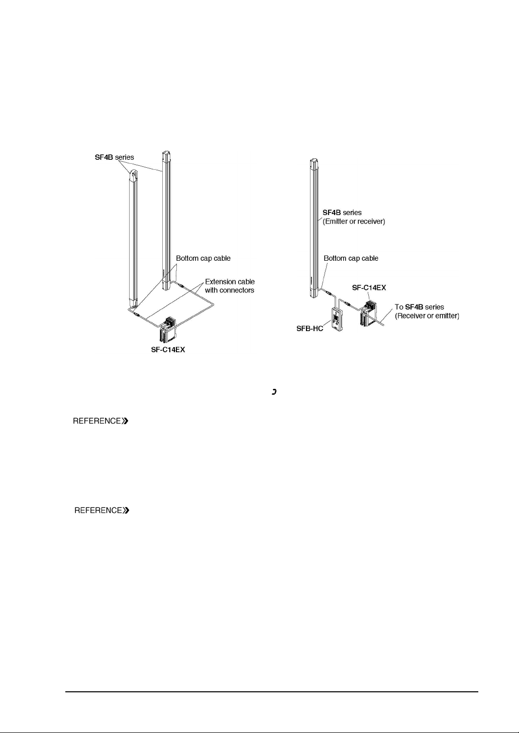
2-3-2 When Using in Combination with Application Expansion Unit SF-C14EX
<The 8-core cable is used>
Ԙ Set the SF4B series and SF-C14EX, and check
that the SF4B series works properly. For details
of mounting method of SF4B series, refer to the
‘SF4B Instruction manual’, and for details of
mounting method of SF-C14EX, refer to
‘SF-C14EX’ Instruction Manual.
ԙTurn off the power, and disconnect the extension
cable with connectors connected to the emitter
side (or receiver side) of SF4B series from
SF-C14EX, and then connect the emitter side (or
receiver side) of this device to the emitter side
(or receiver side) connector of SF-C14EX.
Ԛ Turn on the power, and set the function with SFB-HC.
After the power of this device is on, a total approx. 30 sec. will be taken for data transmission with SF4B
series and SF-C14EX. While data transmission, ’
‘ lights up in revolving.
=The safety output 1 and 2 of SF-C14EX series are set to ‘OFF’ while this device has been connected.?
Refer to ‘3-2 Functional Descriptions < When Using in Combination with Application
Expansion Unit SF-C14EX>’ for the detail of the functions, and refer to ‘3-3 Function
Setting (Operation Procedure)’ for the detail of the setting procedure of the functions
respectively.
ԛ Turn off the power, and remove this device.
Ԝ Connect the SF4B series and SF-C14EX, and return the device to the state described in procedure Ԙ.
ԝ Check that the SF4B series works as set at the procedure Ԛ. Then, inspect the SF4B series.
Refer to ‘Chapter 3 Maintenance’ of the SF4B series instruction manual for the detail of
the inspection of the SF4B series.
SUNX Limited MJE-SFBHC No.6085-02
9
Page 10
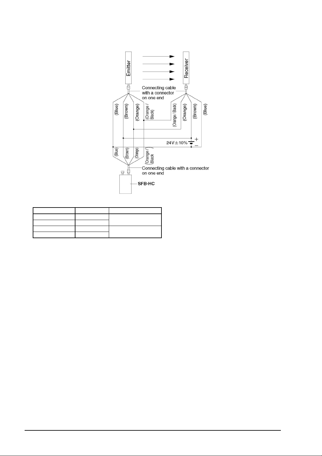
<In case this device cannot be connected between SF4B series and the connecting cable>
This device can be connected to SF4B series by using the connection cable with a connector on one
end (optional).
٨Connection cable with a connector on one end: 2 pcs./set
Model No. Cable length Remarks
SFB-CC3 3m
SFB-CC10 10m
SFB-CC3-MU 3m
SFB-CC10-MU 10m
For 8-core cable
For 12-core cable
The setting procedure remains the same.
The control output (OSSD 1, OSSD 2) of SF4B series is set to ‘OFF’ while this device has been
connected. (The safety output 1 and 2 of SF-C14EX are also set to OFF while SF-C14EX has been
used.) Once the setting is completed, turn off the power, remove this device and then turn on the
power again.
10
SUNX Limited MJE-SFBHC No.6085-02
Page 11
CHAPTER 3 FUNCTIONS
3-1 Functional Descriptions <When Using with Light Curtain SF4B Series Only>
This section describes each function.
When using with SF-C14EX, refer to ‘3-2 Functional Descriptions <When Using in Combination
with Application Expansion Unit SF-C14EX>’.
If configuration of the system is changed (change of the SF-C14EX to be used / not to be used,
replace the sensor etc.), set the function setting again.
3-1-1 Fixed Blanking Function
This is a function that the control output (OSSD 1, OSSD 2) of SF4B series is not turned off, even if the
specified beam channel(s) is blocked off.
This is useful when an obstacle always blocks off the specific beam channel(s).
There are ‘CLR’, ‘AUTO’ and ‘MANUAL’ for the setting method.
CLR setting : The fixed blanking function is to be invalid (Factory setting).
AUTO setting : The currently blocked off beam channels are set as ‘effective beam channels’ in the
fixed blanking function. Be sure to set this function in the state where the emitter emits
light. Furthermore, this function cannot be set in the state where all beam channels
receive lights / are blocked.
Manual setting : Each beam channel can be set to ‘effective / ineffective’ in the fixed blanking function
respectively.
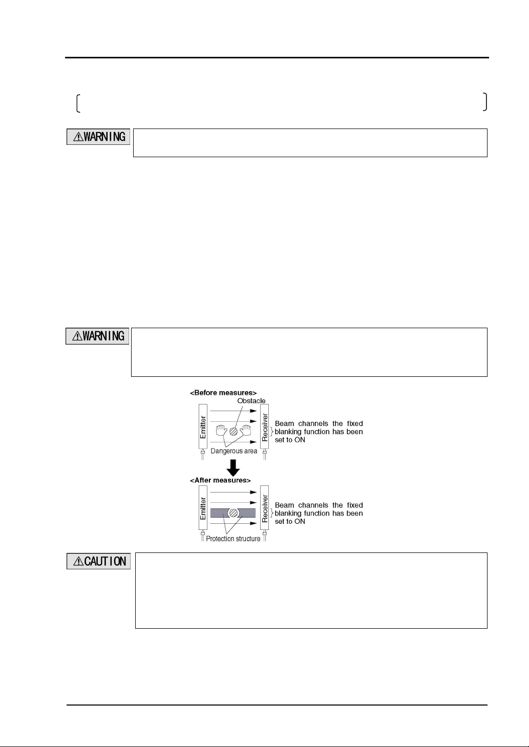
When the fixed blanking function is used, the control output (OSSD 1, OSSD 2) of SF4B series
is not turned off even if the particular beam channels are blocked. By using a protection
structure etc., make the hazardous area of the press machine inaccessible to personnel
through the sensing area of the particular beam channels.
When the effective beam channel(s) in the fixed blanking function receive(s) the beam(s) from
the emitter, the control output (OSSD 1, OSSD 2) of the SF4B series is fixed to ‘OFF’. In this
case, check the mounting condition and turn the power on again.
(Even if the power is turned on again, the fixed blanking function still stays effective.)
When the fixed blanking function is used, the received light intensity indicator of SF4B series
is turned off regardless of the received light intensity.
SUNX Limited MJE-SFBHC No.6085-02
11
Page 12
3-1-2 Floating Blanking Function
s
This function is set in each sensor.
If the number of the blocked beam channels is less than the set number of the beam channels, the control
output (OSSD 1, OSSD 2) of SF4B series is not turned ‘OFF’.
This function is useful when an obstacle moves within the detecting area.
The factory setting of this function is ‘ineffective’.
The following items can be set.
Set number of beam channels
Selectable among 0 (the floating blanking function is ineffective), 1, 2 or 3.
Ineffective setting of both end beam channel
‘Effective’ / ‘Ineffective’ of the floating blanking function for the both ends the beam channels can be selected.
SET (Effective) : The floating blanking function becomes ineffective for the both end beam channels.
In case either end of the beam channel is blocked, the control output (OSSD 1, OSSD 2)
of SF4B series is turned ‘OFF’ regardless of the set number of the beam channels.
CLR (Ineffective) : The floating blanking function becomes effective for all beam channels including
both ends beam channels.
Non-serial beam channel setting
SET (Effective) : Even if the beam channels are blocked discontinuously in the set beam channels,
the control output (OSSD 1, OSSD 2) of SF4B series is turned ‘ON’.
(Discontinuous mode)
CLR (Ineffective) : When the beam channels are blocked discontinuously even in the set beam channels,
the control output (OSSD 1, OSSD 2) of SF4B series is turned ‘OFF’.
(Continuous mode)
When using the floating blanking function, the size of the minimum sensing object become
larger, and the safety distance is longer as well. For the calculation of the safety distance,
refer to the instruction manual enclosed with SF4B series.
Before designing the system, refer to the relevant laws and standards of the region where
SF4B series is to be used and then install SF4B series and this device.
[For use in Europe (EU) (as EN 999)] (Also applicable to ISO 13855)
(For intrusion direction perpendicular to the sensing area)
<In case that the minimum sensing object isǾ40mm or less>
S=KT+C
S: Safety distance (mm)
Minimum required distance between the sensing area surface and the dangerous parts of the machine.
K: Intrusion velocity of operator’s body or object (mm/s)
Taken as 2,000 (mm/s) for calculation
T: Response time of total equipment (s)
m+TSF4B
T=T
m
T
: Maximum halting time of device (s)
SF4B
: Response time of light curtain SF4B series (s)
T
C: Additional distance calculated from the size of the minimum sensing object of the sensor (mm)
However, the value of C cannot be 0 or less.
C=8(d-14)
d: Diameter of the minimum sensing object
<Minimum sensing object>
Floating blanking function
Ineffective
SF4B-FغǾ14mm Ǿ24mm Ǿ34mm Ǿ44mm
SF4B-HغǾ25mm Ǿ45mm Ǿ65mm Ǿ85mm
SF4B-AغǾ45mm Ǿ85mm Ǿ125mm Ǿ165mm
1 beam channel 2 beam channels 3 beam channels
Effective
If the floating blanking function is used, the incident light intensity indicator is turned off when
an obstacle exists in the sensing range regardless of the incident light intensity.
12
SUNX Limited MJE-SFBHC No.6085-02
Page 13

3-1-3 Auxiliary Output Switching Function
This function changes the operation state of the auxiliary output. It is useful when desired to make an
indicator to operate or inform the operation state of the sensor to PLC.
Since the auxiliary output is non-safety output, do not use the auxiliary output for halting the
device.
The following settings are selectable.
Operation of the auxiliary output corresponding to SF4B series state
Setting
mode
0
1
2 ON when emitting OFF ON OFF
3 OFF when emitting ON OFF ON
4
5
6 ON during muting OFF
7 OFF during muting ON
8
9
Notes: 1) When the fixed blanking function, the floating blanking function or the muting function is used, the setting of ON / OFF
Auxiliary output setting
Negative logic of the control
output (OSSD 1, OSSD 2)
(factory setting)
Positive logic of the control
output (OSSD 1, OSSD 2)
OFF under unstable light
receiving condition (Note 1)
ON under unstable light
receiving condition (Note 1)
ON in light receiving
condition (Note 2)
OFF in light receiving
condition (Note 2)
under unstable light-receiving condition does not work.
2) By the setting of ON / OFF in light receiving condition, light-receiving / light interrupted condition is output regardless of
the fixed blanking function, the floating blanking function or the muting function.
<e.g.>
When the fixed blanking function is used, if an obstacle exists in the set area and other area is in light receiving condition,
the control output (OSSD 1, OSSD 2) is in ON sate, however, the auxiliary output becomes OFF since the sensor has
been detecting the obstacle.
3) The state of the auxiliary output remains the same even if the SF4B series state changes.
Emission
halt
ON
OFF
(Note 3) OFF ON (Note 3) (Note 3)
(Note 3) ON OFF (Note 3) (Note 3)
OFF ON OFF OFF
ON OFF ON ON
State of detecting area when emitting
Unshielded
Unstable
lightreceiving
condition
Others
OFF when OSSD is ON
ON when OSSD is OFF
ON when OSSD is ON
OFF when OSSD is OFF
ON during muting
Others: OFF
OFF during muting
Others: ON
Shielded
Lockout
ON
OFF
OFF
ON
3-1-4 Emission Intensity Control Function
This function reduces the emitting intensity. It is useful for preventing interference from the emitter to the
other devices.
Emission intensity control
CLR (Ineffective) : Operating range is 0.3 to 9m for SF4B-Hغ (12 to 64 beam channels) and SF4B-Aغ
(6 to 32 beam channels), 0.3 to 7m for SF4B-Fغ and SF4B-Hغ (72 to 96 beam
channels) and SF4B-Aغ (36 to 48 beam channels) (factory setting).
SET (Effective) : The operating range is reduced by approx. 50%.
SUNX Limited MJE-SFBHC No.6085-02
13
Page 14

3-1-5 Copy Function
This is a function to copy the setting of a sensor to other sensors.
This function is available only under the same system configuration (No. of sensors, No. of beam channel,
same model No.).
All functions that are settable with this device can be copied.
Note that the password is also copied with this function.
The following operations are available with this function.
Upload : Upload the functional setting data of light curtain SF4B series to this device.
Download : Download the functional setting data of this device to light curtain SF4B series.
Monitoring : Check the functional setting data saved in this device.
3-1-6 Muting Setting Changing Function
The setting of the muting function can be changed.
Setting of the muting function on each beam channel
Each beam channel can be set to ‘effective / ineffective’ in the muting function respectively. (Note)
The factory setting of this function is effective for all beam channels.
Note: If the beam channel set to ineffective in the muting function is blocked, the control output (OSSD 1, OSSD 2) becomes
‘OFF’ and the muting function is canceled.
There are two setting methods, ‘AUTO’ and ‘MANUAL’ to set muting beam channel.
AUTO setting : The beam channel which is currently blocked is set as the ‘effective’ beam channel.
When all beam channels are in light receiving condition, the setting is not accepted.
Furthermore, in the state where emission is halted or all beam channels are blocked,
the all beam channels become ‘effective’ in the muting function.
Manual setting : Each beam channel can be set to ‘effective / ineffective’ in the muting function.
ON: The muting function is effective
OFF: The muting function is ineffective
Muting input conditions
The order for inputting the muting input A, and B, which the muting function activates, can be set.
A㧩b: Effective even either comes first
A b: Effective only when the input A comes first
b A: Effective only when the input B comes first
Note: The setting is possible for each channel.
Setting of the muting lamp diagnosis function
The muting lamp diagnosis function can be set to ‘effective / ineffective’. (Note)
The factory setting of this function is effective.
ON: The muting lamp diagnosis function is effective.
OFF: The muting lamp diagnosis function is ineffective.
Note: If the muting lamp diagnosis function is set to ineffective, the muting function is maintained even if the lamp blew.
3-1-7 Interlock Setting Changing Function
One condition can be selected from the following three interlock conditions. It can be set to invalid, too. (Mode 3)
Start / Restart interlock(Mode 0)
The sensor goes into interlock condition after the power is ON and when it is in the light receiving condition.
The factory setting is Start / Restart interlock.
14
SUNX Limited MJE-SFBHC No.6085-02
Page 15

Start interlock (Mode 1)
t
The sensor goes into interlock condition only when the power is ON. Once the sensor is reset, it does not
go into interlock condition again.
Restart interlock (Mode 2)
The sensor does not go into the interlock condition when the power is ON. The sensor goes into interlock
condition only when the sensor receives the light, after the power is ON, the control output (OSSD 1, OSSD 2)
is turned into ON once and then the sensor is blocked.
3-1-8 External Device Monitor Setting Changing Function
The setting of the external device monitor can be changed.
1. Allowable period of the response time: 100 to 600ms (unit of 10ms)
The factory setting is 300ms.
2. ‘Effective / Ineffective’ of the external device monitor function can be selected.
The factory setting is ‘Effective’.
3-1-9 Protect Function
The functional settings are not allowed to change without the input of a password.
When the protect function is set to ‘Effective’, the setting can be changed by inputting the password.
The setting contents monitor function can be used regardless of the protect function ‘Effective / Ineffective’.
The password should be a 4-digit number from 0 to 9. (The password of the factory setting is ‘0000’.)
The protect function is set on the receiver side.
㨯When the protecting function is set to ‘Ineffective’, the third person may change the setting. I
is recommended that the protecting function should be set to ‘Effective’ so as not to change
the setting by the third person.
㨯Take sufficient care not to forget the set password. In case you forget the password, please
contact us.
3-1-10 Initialization Function
The settings can be initialized. (factory setting) (Note)
The factory setting of each function is as follows.
Fixed blanking function Ineffective
Floating blanking function Ineffective
Auxiliary output switching function Mode: 0
Emission intensity control function Normal mode
Muting setting changing function
Interlock setting changing function Start / Restart
External devise monitor setting changing function Effective / 300ms
Note: The setting of the protect function and the setting data of the copy function are not initialized.
Function Setting
Effective for all beam
channels A㧩B
3-1-11 Setting Contents Monitoring Function
Each setting of the sensor can be monitored. The following can be monitored.
Model No. / the number of beam channel
Setting of the fixed blanking function (Reading out the record of the latest 5 times is possible)
Setting of the floating blanking function (Reading out the record of the latest 5 times is possible)
Setting of the auxiliary output switching function
Setting of the emission intensity control function
Setting of the interlock setting changing function
Setting of the external device monitor setting changing function
Setting of the muting setting changing function
(Reading out the record of the latest 5 times is possible, however, only for setting beam channel.)
SUNX Limited MJE-SFBHC No.6085-02
15
Page 16

3-2 Functional Descriptions <When Using in Combination with Application Expansion Unit
k
SF-C14EX>
This section describes each function.
If configuration of the system is changed (replacement of the SF-C14EX, series connection,
change the number of the beam channels etc.), set the function setting again. When using in
combination with the SF-C14EX, a part of the SF4B functions is changed as well.
3-2-1 Fixed Blanking Function
This is a function that the safety output 1 and 2 of SF-C14EX are not turned off, even if the specified beam
channel(s) is blocked off.
This is useful when an obstacle always blocks off the specific beam channel(s).
There are ‘CLR’, ‘AUTO’ and ‘MANUAL’ for the setting method.
CLR setting : The fixed blanking function is to be invalid (Factory setting).
AUTO setting : The currently blocked off beam channels are set as ‘effective beam channels’ in the
fixed blanking function. Be sure to set this function in the state where the emitter emits
light. Furthermore, this function cannot be set in the state where all beam channels
receive lights / are blocked.
Manual setting : Each beam channel can be set to ‘effective / ineffective’ in the fixed blanking function
respectively.
When the fixed blanking function is used, the safety output 1 and 2 of SF-C14EX are not turned
off even if the particular beam channels of SF4B series are blocked. By using a protection
structure etc., make the hazardous area of the press machine inaccessible to personnel
through the sensing area of the particular beam channels of SF4B series.
When the effective beam channel(s) in the fixed blanking function receive(s) the beam(s) from
the emitter, the safety output 1 and 2 of the SF-C14EX are fixed to ‘OFF’. In this case, chec
the mounting condition and turn the power on again.
(Even if the power is turned on again, the fixed blanking function still stays effective.)
When the fixed blanking function is used, the received light intensity indicator of SF4B series
is turned off regardless of the received light intensity.
16
SUNX Limited MJE-SFBHC No.6085-02
Page 17

3-2-2 Floating Blanking Function
s
g
This function is set in each sensor.
If the number of the blocked beam channels is less than the set number of the beam channels, the safety
output 1 and 2 of SF-C14EX are not turned ‘OFF’.
This function is useful when an obstacle moves within the detecting area of SF4B series.
The factory setting of this function is ‘ineffective’.
The following items can be set.
Set number of beam channels
Selectable among 0 (the floating blanking function is ineffective), 1, 2 or 3.
Ineffective setting of both end beam channel
‘Effective’ / ‘Ineffective’ of the floating blanking function for the both ends the beam channels can be
selected.
SET (Effective) : The floating blanking function becomes ineffective for the both end beam channels.
If either end of the beam channel is blocked, the safety output 1 and 2 of
SF-C14EX are turned ‘OFF’ regardless of the set number of the beam channels.
CLR (Ineffective) : The floating blanking function becomes effective for all beam channels including
both ends beam channels.
Non-serial beam channel setting
SET (Effective) : Even if the beam channels are blocked discontinuously in the set beam channels,
the safety output 1 and 2 of SF-C14EX are turned ‘ON’. (Discontinuous mode)
CLR (Ineffective) : When the beam channels are blocked discontinuously even in the set beam channels,
the safety output 1 and 2 of SF-C14EX are turned ‘OFF’. (Continuous mode)
When using the floating blanking function, the size of the minimum sensing object become
larger, and the safety distance is longer as well. For the calculation of the safety distance,
refer to the instruction manual enclosed with SF4B series.
Before designing the system, refer to the relevant laws and standards of the region where
SF4B series is to be used and then install SF4B series and this device.
The minimum sensing object differs depending on the set number of the beam channels.
[For use in Europe (EU) (as EN 999)] (Also applicable to ISO 13855)
(For intrusion direction perpendicular to the sensing area)
<In case that the minimum sensing object isǾ40mm or less>
S=KT+C
S: Safety distance (mm)
Minimum required distance between the sensing area surface and the dangerous parts of the machine.
K: Intrusion velocity of operator’s body or object (mm/s)
Taken as 2,000 (mm/s) for calculation
T: Response time of total equipment (s)
m+TSFC14EX
T=T
m
T
T
: Maximum halting time of device (s)
SFC14EX
: Response time of SF-C14EX (s)
C: Additional distance calculated from the size of the minimum sensing object of the sensor (mm)
However, the value of C cannot be 0 or less.
C=8(d-14)
d: Diameter of the minimum sensing object
<Minimum sensing object>
Floating blanking function
Ineffective
SF4B-FغǾ14mm Ǿ24mm Ǿ34mm Ǿ44mm
SF4B-HغǾ25mm Ǿ45mm Ǿ65mm Ǿ85mm
SF4B-AغǾ45mm Ǿ85mm Ǿ125mm Ǿ165mm
1 beam channel 2 beam channels 3 beam channels
Effective
If the floating blanking function is used, the incident light intensity indicator is turned off when
an obstacle exists in the sensin
range regardless of the incident light intensity.
SUNX Limited MJE-SFBHC No.6085-02
17
Page 18

3-2-3 Auxiliary Output Switching Function
This function changes the operation state of the auxiliary output (AUX4) of SF-C14EX. It is useful when
desired to make an indicator to operate or inform the operation state of the sensor to PLC.
Since the auxiliary output is non-safety output, do not use the auxiliary output for halting the
device.
The following settings are selectable.
Operation of the auxiliary output corresponding to SF4B series state
Setting
mode
0
1
2 ON when emitting OFF ON OFF
3 OFF when emitting ON OFF ON
4
5
6 ON during muting OFF (Note 4)
7 OFF during muting ON (Note 4)
8
9
Notes: 1) When the fixed blanking function, the floating blanking function or the muting function is used, the setting of ON / OFF
Auxiliary output setting
Negative logic of the control
output (OSSD 1, OSSD 2)
(factory setting)
Positive logic of the control
output (OSSD 1, OSSD 2)
OFF under unstable light
receiving condition (Note 1)
ON under unstable light
receiving condition (Note 1)
ON in light receiving
condition (Note 2)
OFF in light receiving
condition (Note 2)
under unstable light-receiving condition does not work.
2) By the setting of ON / OFF in light receiving condition, light-receiving / light interrupted condition is output regardless of
the fixed blanking function, the floating blanking function or the muting function.
<e.g.>
When the fixed blanking function is used, if an obstacle exists in the set area and other area is in light receiving condition,
the safety output 1, 2 are in ON sate, however, the auxiliary output becomes OFF since the sensor has been detecting
the obstacle.
3) The state of the auxiliary output remains the same even if the SF4B series state changes.
4) When using in combination with SF-C14EX, the muting function cannot be set on SF4B side. Thus, the state of the
auxiliary output remains the same regardless of the SF4B series state.
Emission
halt
ON
OFF
(Note 3) OFF ON (Note 3) (Note 3)
(Note 3) ON OFF (Note 3) (Note 3)
OFF ON OFF OFF
ON OFF ON ON
State of detecting area when emitting
Unshielded
Unstable
lightreceiving
condition
Others
OFF when OSSD is ON
ON when OSSD is OFF
ON when OSSD is ON
OFF when OSSD is OFF
Shielded
Lockout
ON
OFF
3-2-4 Emission Intensity Control Function
This function reduces the emitting intensity. It is useful for preventing interference from the emitter to the
other devices.
Emission intensity control
CLR (Ineffective) : Operating range is 0.3 to 9m for SF4B-Hغ (12 to 64 beam channels) and
SF4B-Aغ (6 to 32 beam channels), 0.3 to 7m for SF4B-Fغ and SF4B-Hغ
(72 to 96 beam channels) and SF4B-Aغ (36 to 48 beam channels) (factory
setting).
SET (Effective) : The operating range is reduced by approx. 50%.
18
SUNX Limited MJE-SFBHC No.6085-02
Page 19

3-2-5 Copy Function
This is a function to copy the setting of a sensor to other sensors.
This function is available only under the same system configuration (No. of sensors, No. of beam channel,
same model No.).
All functions that are settable with this device can be copied.
Note that the password is also copied with this function.
The following operations are available with this function.
Upload : Upload the functional setting data of light curtain SF4B series or SF-C14EX to this device.
Download : Download the functional setting data of this device to light curtain SF4B series or SF-C14EX.
Monitoring : Check the functional setting data saved in this device.
3-2-6 Muting Setting Changing Function
The setting of the muting function can be changed.
Setting of the muting function on each beam channel
Each beam channel can be set to ‘effective / ineffective’ in the muting function respectively. (Note)
The factory setting of this function is effective for all beam channels.
Note: If the beam channel set to ineffective in the muting function is blocked, the safety output 1 and 2 of SF-C14EX becomes
‘OFF’ and the muting function is canceled.
There are two setting methods, ‘AUTO’ and ‘MANUAL’ to set muting beam channel.
AUTO setting : The beam channel which is currently blocked is set as the ‘effective’ beam channel.
When all beam channels are in light receiving condition, the setting is not accepted.
Furthermore, in the state where emission is halted or all beam channels are blocked,
the all beam channels become ‘effective’ in the muting function.
Manual setting : Each beam channel can be set to ‘effective / ineffective’ in the muting function.
ON: The muting function is effective
OFF: The muting function is ineffective
Muting input conditions
The order for inputting the muting input A, and B, which the muting function activates, can be set.
A㧩b: Effective even either comes first
A b: Effective only when the input A comes first
b A: Effective only when the input B comes first
Note: The setting is possible for each channel.
Setting of the muting lamp diagnosis function
The muting lamp diagnosis function can be set to ‘effective / ineffective’. (Note)
The factory setting of this function is effective.
ON: The muting lamp diagnosis function is effective.
OFF: The muting lamp diagnosis function is ineffective.
Note: If the muting lamp diagnosis function is set to ineffective, the muting function is maintained even if the lamp blew.
3-2-7 Interlock Setting Changing Function
This function cannot be set when SF-C14EX is used.
3-2-8 External Device Monitor Setting Changing Function
This function cannot be set when SF-C14EX is used.
SUNX Limited MJE-SFBHC No.6085-02
19
Page 20

3-2-9 Protect Function
t
The functional settings are not allowed to change without the input of a password.
When the protect function is set to ‘Effective’, the setting can be changed by inputting the password.
The setting contents monitor function can be used regardless of the protect function ‘Effective / Ineffective’.
The password should be a 4-digit number from 0 to 9. (The password of the factory setting is ‘0000’.)
The protect function is set on the SF-C14EX.
㨯When the protecting function is set to ‘Ineffective’, the third person may change the setting. I
is recommended that the protecting function should be set to ‘Effective’ so as not to change
the setting by the third person.
㨯Take sufficient care not to forget the set password. In case you forget the password, please
contact us.
3-2-10 Initialization Function
The settings can be initialized. (factory setting) (Note1)
The factory setting of each function is as follows.
Fixed blanking function Ineffective
Floating blanking function Ineffective
Auxiliary output switching function Mode: 0
Emission intensity control function Normal mode
Muting setting changing function
Muting lamp diagnosis function Effective
Interlock setting changing function (Note 2)
External devise monitor setting changing function (Note 2)
Notes: 1) The setting of the protect function and the setting data of the copy function are not initialized.
2) This function cannot be set when SF-C14EX is used.
Function Setting
Effective for all beam
channels A㧩B
3-2-11 Setting Contents Monitoring Function
Each setting of the sensor can be monitored. The following can be monitored.
Model No. / the number of beam channel
Setting of the fixed blanking function (Reading out the record of the latest 5 times is possible)
Setting of the floating blanking function (Reading out the record of the latest 5 times is possible)
Setting of the auxiliary output switching function
Setting of the emission intensity control function
Setting of the muting setting changing function
(Reading out the record of the latest 5 times is possible, however, only for setting beam channel.)
20
SUNX Limited MJE-SFBHC No.6085-02
Page 21

3-3 Function Setting (Operation Procedure)
This section describes the setting of each function (operation procedure).
<Selecting the setting item>
Select a setting item with FUNCTION or CANCEL switch, and confirm it with ENTER.
SUNX Limited MJE-SFBHC No.6085-02
21
Page 22

<Inputting a password>
When the protect function is effective, ‘Lock’ is shown on the lower section of the digital display. The
functional settings of the sensor cannot be changed unless the password is input. Note that ‘3-3-9 Protect
Function’ is ‘locked’ even when the protect function is ineffective.
1‘3-3-11 Setting Contents Monitoring Function’ is not ‘locked’.
2) Once the password is input, you do not need to input the password again till the power is turned
off. (Except ‘3-3-9 Protect Function’) However, if the power is turned on again without changing
the protect function to ineffective, the password have to be input again since the protect function is
still effective.
The procedure for inputting a password is as follows.
22
SUNX Limited MJE-SFBHC No.6085-02
Page 23

<Selecting sensor>
Each function can be set on each sensor connected in series as well. Select a sensor to set each function.
Since ‘3-3-5 Copy Function’ and ‘3-3-9 Protect Function’ are set collectively, it is not necessary to
select a sensor. Furthermore, when a sensor unit is used, CH2 / CH3 cannot be selected. When two
sensors in series connection are used, CH3 cannot be selected.
‘3-3-4 Auxiliary Output Switching Function’, ‘3-3-7 Interlock Setting Changing Function’ or
‘3-3-8 External Device Monitor Setting Changing Function’ is set with CH1 only. CH2 and CH3 are
not indicated.
When using in combination with SF-C14EX, the setting of ‘3-3-7 Interlock Setting Changing
Function’ and ‘3-3-8 External Device Monitor Setting Changing Function’ cannot be changed.
*: When the units are not in series connection, it is not indicated.
SUNX Limited MJE-SFBHC No.6085-02
23
Page 24

3-3-1 Fixed Blanking Function
*: The functional setting for each beam channel is as follows.
on : The fixed blanking function is effective.
oFF : The fixed blanking function is ineffective.
24
SUNX Limited MJE-SFBHC No.6085-02
Page 25

3-3-2 Floating Blanking Function
FLO1 <Effective setting of beam channel>
0 : Ineffective
1: 1 beam channel setting
2 : 2 beam channels setting
3 : 3 beam channels setting
FLO2 <Ineffective setting of both end beam channel>
SET (Effective) : Both ends of the beam channels are not subject to the float blanking function
CLR (Ineffective) : All beam channels are subject to the float blanking function
FLO3 <Non serial beam channel setting>
SET (Effective) : Non-serial beam channel mode
CLR (Ineffective) : Serial beam channel mode
Note: When ‘all sensors’ is selected in the sensor selection, the setting of the floating blanking function on each sensor should be
identical.
SUNX Limited MJE-SFBHC No.6085-02
25
Page 26

3-3-3 Auxiliary Output Switching Function
*: When 2 or more sensors are connected, cancel the protect function of all sensors.
<Setting of the auxiliary output>
Mode 0: Negative logic of the control output (OSSD 1, OSSD 2) (factory setting)
Mode 1: Positive logic of the control output (OSSD 1, OSSD 2)
Mode 2: ON during emission, OFF when emission is not done.
Mode 3: OFF during emission, ON when emission is not done.
Mode 4: OFF when the received light level is unstable (Note 1)
Mode 5: ON when the received light level is unstable (Note 1)
Mode 6: ON during muting
Mode 7: OFF during muting
Mode 8: ON in the light receiving condition
Mode 9: OFF in the light receiving condition
Notes: 1) This cannot be used when the fixed blanking function, the floating blanking function or the muting setting changing function is
used.
2) When using with SF4B series only, if the external device monitor function is not used, set the monitor setting to ineffective
in ‘3-3-8 External Device Monitor Setting Changing Function’.
26
SUNX Limited MJE-SFBHC No.6085-02
Page 27

3-3-4 Emission Intensity Control Function
<Emission intensity control>
CLR (Ineffective) : Operating range is 0.3 to 9m for SF4B-Hغ (12 to 64 beam channels) and SF4B-Aغ
(6 to 32 beam channels), 0.3 to 7m for SF4B-Fغ and SF4B-Hغ (72 to 96 beam
channels) and SF4B-Aغ (36 to 48 beam channels) (factory setting).
SET (Effective) : The operating range is reduced by approx. 50%.
SUNX Limited MJE-SFBHC No.6085-02
27
Page 28

3-3-5 Copy Function
*: The setting of the relay monitor is as follows.
When set to ineffective: CLR
When set to effective: Set time (100 to 600ms, unit of 10ms)
Notes: 1) The indication is on the main sensor (CH1) only.
2) When using in combination with SF-C14EX, it is not indicated.
28
SUNX Limited MJE-SFBHC No.6085-02
Page 29

3-3-6 Muting Setting Changing Function
*: The functional setting of each beam channel is as follows.
on : The muting function is effective.
oFF : The muting function is ineffective.
*1: CLR initializes the all settings. (factory setting)
All beam channels: Effective
Input condition: A㧩b
Muting lamp diagnosis function: Effective
*2: When only the setting of the input condition is changed, set it by manual setting.
*3: When only the beam channel which the muting is effective is initialized, set to the auto setting in the
emission halt condition.
Notes: 1) ‘ALL’ is displayed only when set by ‘Auto’.
2) When only using the light curtains, set the muting lamp diagnosis function on all sensors. However, if the function has
been set through CLr / Auto / ManU on each sensor, set the function on the sensor.
When using SF-C14EX, this function is set on the SF-C14EX. In this case, set the function in the same way when
‘ALL’ is selected.
SUNX Limited MJE-SFBHC No.6085-02
29
Page 30

3-3-7 Interlock Setting Changing Function
*: When 2 or more sensors are connected, cancel the protect function of all sensors.
<Setting of the interlock>
Mode 0: Start / restart interlock function (factory setting)
Mode 1: Start interlock function
Mode 2: Restart interlock function
Mode 3: Ineffective
Note: When using SF-C14EX, the display does not change even if ENTER key is pressed. (Mode 0 / Start / reset interlock function)
30
SUNX Limited MJE-SFBHC No.6085-02
Page 31

3-3-8 External Device Monitor Setting Changing Function
*: When 2 or more sensors are connected, cancel the protect function of all sensors.
<External device monitor>
CLR (Ineffective) : The external device monitor function is ineffective.
SET (Effective) : The external device monitor function is effective. (The factory setting is 300ms.
Note: When using SF-C14EX, the display does not change even if ENTER key is pressed. (The external device monitor: Effective)
SUNX Limited MJE-SFBHC No.6085-02
31
Page 32

3-3-9 Protect Function
When using with SF4B series only
*: When the units are connected in series, the indication is as follows.
CH1:
CH2:
CH3:
When using in combination with SF-C14EX
32
SUNX Limited MJE-SFBHC No.6085-02
Page 33

3-3-10 Initialization Function
SUNX Limited MJE-SFBHC No.6085-02
33
Page 34

3-3-11 Setting Contents Monitoring Function
Notes: 1) The indication is on the main sensor (CH1) only.
2) When using SF-C14EX, this is not indicated.
34
SUNX Limited MJE-SFBHC No.6085-02
Page 35

CHAPTER 4 TROUBLESHOOTING
Symptoms Cause Remedy
Control output (OSSD 1,
OSSD 2) is not turned
ON.
Symptoms Cause Remedy
Safety output 1, 2 are
not turned ON.
Error indication Cause Remedy
Note: The factory setting of the SF4B series password is ‘0000’.
This device is connected to the
SF4B series.
This device is connected to the
SF-C14EX.
The fixed blanking function is set in
all beams received / all beams
blocked condition, or the muting
function is set in all beams received
condition.
The copy function is used for the
units having different system
configuration from each other
Sensor No. / the beam channel
No. / model No. is not same.
In the copy function, download the
data without uploading.
The password does not match.
Sensor communication error Ԙ
(Model No. is wrong)
Sensor communication error ԙ
Wrong wiring between the
emitter and receiver.
Sensor communication error Ԛ
Effect from noise or failure of
internal circuit
Failure of EEPROM in this device.
(Failure on device)
Failure of EEPROM in this device.
(Failure on EEPROM data)
Disconnect this device.
Disconnect this device.
Do not set the fixed blanking function in all beams received /
all beams blocked condition, or the muting function in all
beams received condition.
Use the copy function for the units having identical system
configuration.
Upload the data before downloading.
Input the correct password. In case you forget the password,
contact us. (Note)
Connect this device to SF4B series.
Connect the emitter and receiver correctly.
Check the noise state around the sensor.
Contact us.
Contact us.
If this device does not work, press ENTER key or CANCEL key one minute after pressing ENTER
key.
If the device does not work correctly after checking the items above, please consult us.
SUNX Limited MJE-SFBHC No.6085-02
35
Page 36

CHAPTER 5 SPECIFICATIONS / DIMENSIONS
5-1 Specifications
Item
Applicable model Light curtain SF4B series, Application expansion unit SF-C14EX
Supply voltage 24V DCr10% Ripple P-P 10% or less (common to sensor power supply)
Current consumption 65mA or less
Communication
method
Digital display 4-digit red LED display 2 (selected beam channels, setting contents etc. are displayed. )
FUNCTION indicator Green LED9 (lights up when each functional setting is ON)
Functions
Ambient temperature -10 to +55㷄 (No dew condensation or icing allowed), Storage: -25 to +70
Ambient humidity 30 to 85% RH, Storage: 30 to 85% RH
Voltage
withstandability
Insulation resistance 20Mǡor more, with 500 V DC megger between all supply terminals connected together and enclosure
Cable 8-core shielded cable with a connector on one end 0.5m long (2 pcs.)
Weight 200g approx.
Accessory SFB-CCJ02-HC (Conversion cable): 2 pcs.
Notes: 1) There may be a case that the copied data through the copy function is deleted due to external causes. After the copy
Model No.
RS-485 two-way communications (specific procedure)
٨ Fixed blanking function ٨ Floating blanking function ٨ Auxiliary output switching function
٨ Emission intensity control function ٨ Copy function (Note) ٨ Muting setting changing function
٨ Interlock setting changing function (Note 2) ٨ External device monitor setting changing function (Note 2)
٨ Protect function ٨ Initialization function ٨ Setting contents monitoring function
1,000V AC for one minute between all supply terminals connected together and enclosure
function was used, check the copied data.
2) When using in combination with SF-C14EX, the setting cannot be changed.
5-2 Dimensions (Unit: mm)
SFB-HC (Ver.2)
36
SUNX Limited MJE-SFBHC No.6085-02
Page 37

Revision history
First edition 2005/5/13
Second edition 2005/07/14
SUNX Limited MJE-SFBHC No.6085-02
37
Page 38

[Warranty Period]
Unless otherwise agreed, SUNX warrants this product for twelve (12) months from the date of the
shipment or delivery to the purchaser’s appointed warehouse. However, note that consumables of
the product, such as batteries or lamps etc. are not covered.
[Scope of Warranty]
During the above mentioned period, if a failure of the product occurs under normal use and
operation, and if SUNX determines that it is responsible for the failure, it shall repair the defect or
replace the product.
However, in no event shall SUNX be liable for the failure, damage or loss stipulated below:
(1) Failure caused by instructions, standards, or handling specified by the customer.
(2) Failure caused by modifications done in the structure, capabilities, specifications, etc., without
consulting SUNX, after the purchase or the delivery of the product.
(3) Failure caused by a development which could not be foreseen based upon the technology in
proactive at the time of purchase or contract.
(4) Failure caused by use which deviates from the conditions/environment given in the product
catalog or specifications.
(5) In case this product is used by being incorporated in the customer’s machine, failure which
could be avoided if the customer’s machine had functions and structure commonly accepted
in the industry.
(6) Failure due to Force Majeure
Further, the warranty given here is limited only to this product which has been purchased or
delivered. SUNX shall not be responsible for any consequential damage or loss arising out of the
failure of this product.
[Scope of Service]
The cost of the delivered product does not include the cost of dispatching an engineer, etc. In case
any such service is needed, it should be separately requested.
 Loading...