How it Works
Log In / Sign Up
Buy Points
How it Works
FAQ
Contact Us
Questions and Suggestions
Users
Panasonic
Loading...
S
SF4B-H32G(V2)
SF4B-H36C
SF4B-H36CA-J05
SF4B-H36G(V2)
SF4B-H36(V2)
5
SF4B-H40C
SF4B-H40CA-J05
SF4B-H40G(V2)
SF4B-H48C
SF4B-H48CA-J05
SF4B-H48G(V2)
SF4B-H56C
SF4B-H56CA-J05
SF4B-H56G(V2)
SF4B-H64C
SF4B-H64CA-J05
SF4B-H64G(V2)
SF4B-H72C
SF4B-H72CA-J05
SF4B-H72G(V2)
SF4B-H80G(V2)
SF4C-F15
SF4C-F15-J05
SF4C-F23
SF4C-F23-J05
SF4C-F31
SF4C-F31-J05
SF4C-F39
SF4C-F39-J05
SF4C-F47
SF4C-F47-J05
SF4C-F55
SF4C-F63
SF4C-F-J05 Series
SF4C-F Series
SF4C-H12
2
SF4C-H16
SF4C-H20
SF4C-H24
7
SF4C-H28
7
SF4C-H32
7
SF4C-H8
2
SF4C-H-J05 Series
SF4C-H Series
SF4D
2
SF4D-*-01
SF4D-A*-01
SF4D-F*-01
SF4D-H*-01
SF4D-x-01
SFB-HC
2
SFC-HC
SFD-WL3
SFDX7
SG-1010
SG-1030
SG-1050
SG-1060
SG-1090
SG-1200
SG-152
SG-165
SG-2050
SG-2070
SG-2100
SG-235
SG-240
SG 2 5,5
SG-3000
SG-3060
SG-3090
SG-3200
SG-3220
SG-4000
SG-5000
SG-5070
SG-5090
SG-6000
SG-6070
SG-B2
SG-C1-21
SG-C1-21-E
SG-C1-21-EG
SG-C1-21-EMK
SG-C1-21-EMM
SG-HM09A
SG-HM10
SG-HM22
SG-HM30
SG-HM32
SG-HM35L
SG-HM42
SG-K366
SH-67
SH-8038
sh-ac300
SH-AC500D
SH-ALL1C
6
SH-CDC12PEY
SH-DJ1200
2
Loading...
Loading...
Nothing found
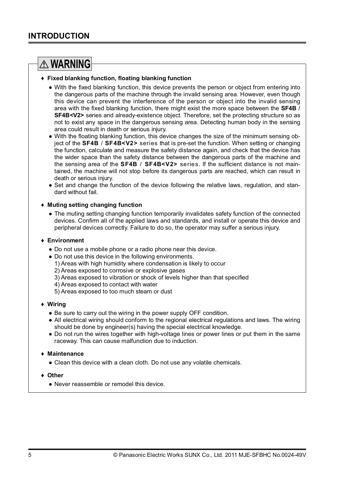
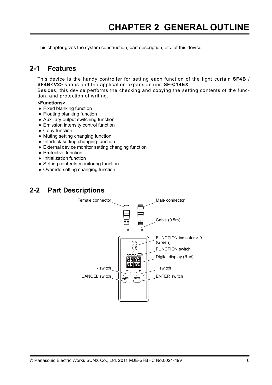
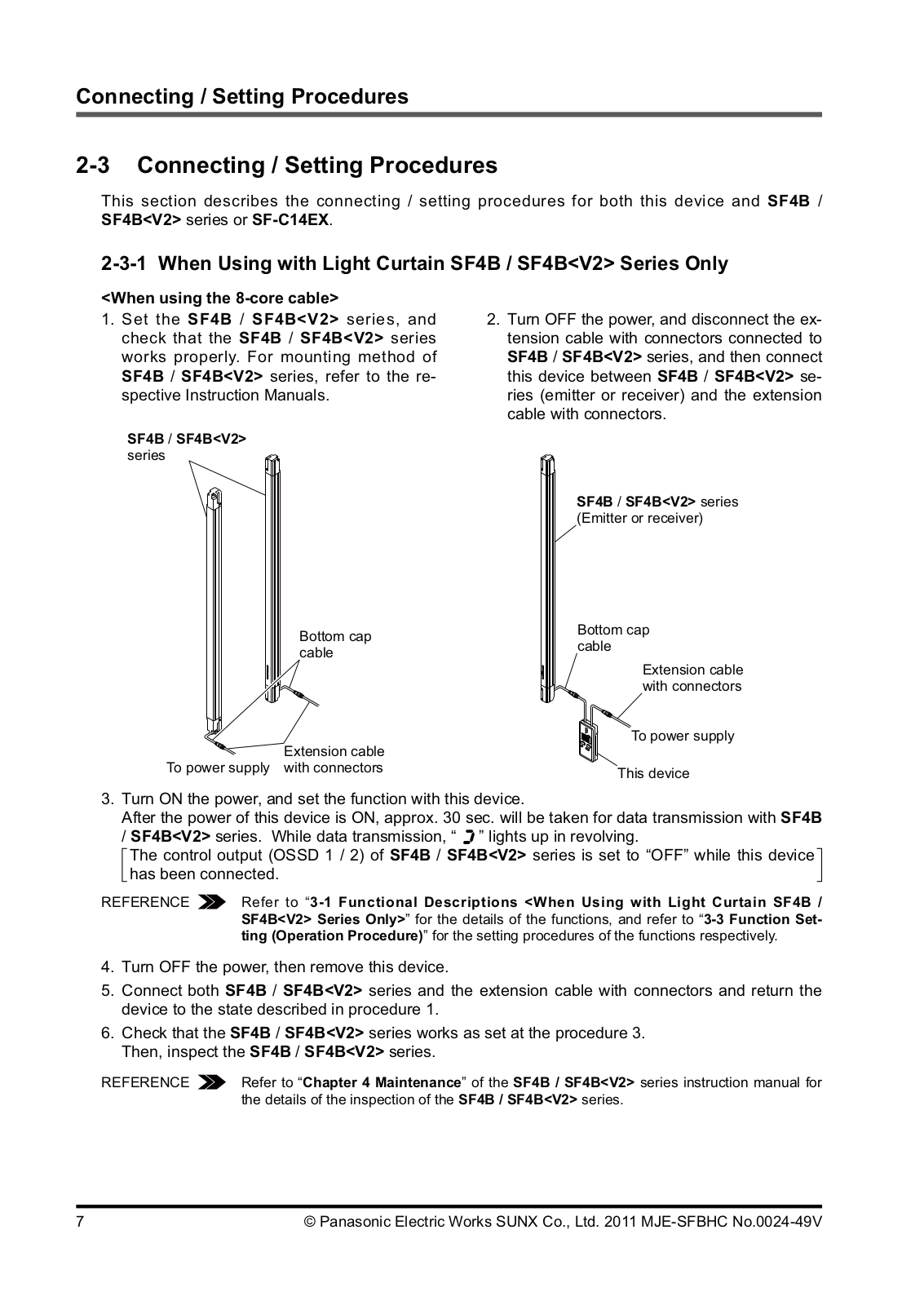
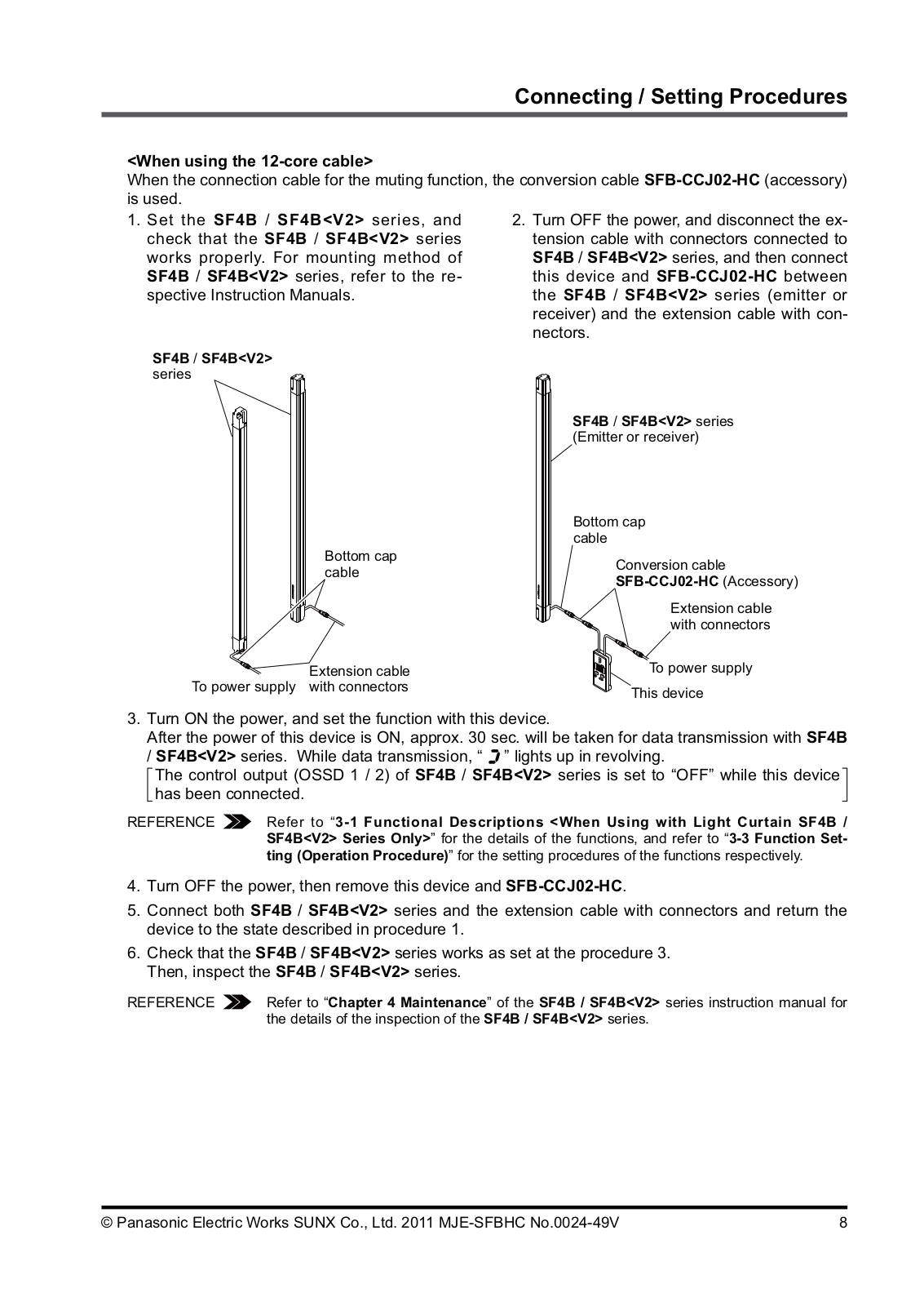
SFB-HC
Installation Manual
38 pgs
4.64 Mb
0
Instruction Manual
44 pgs
622.95 Kb
0
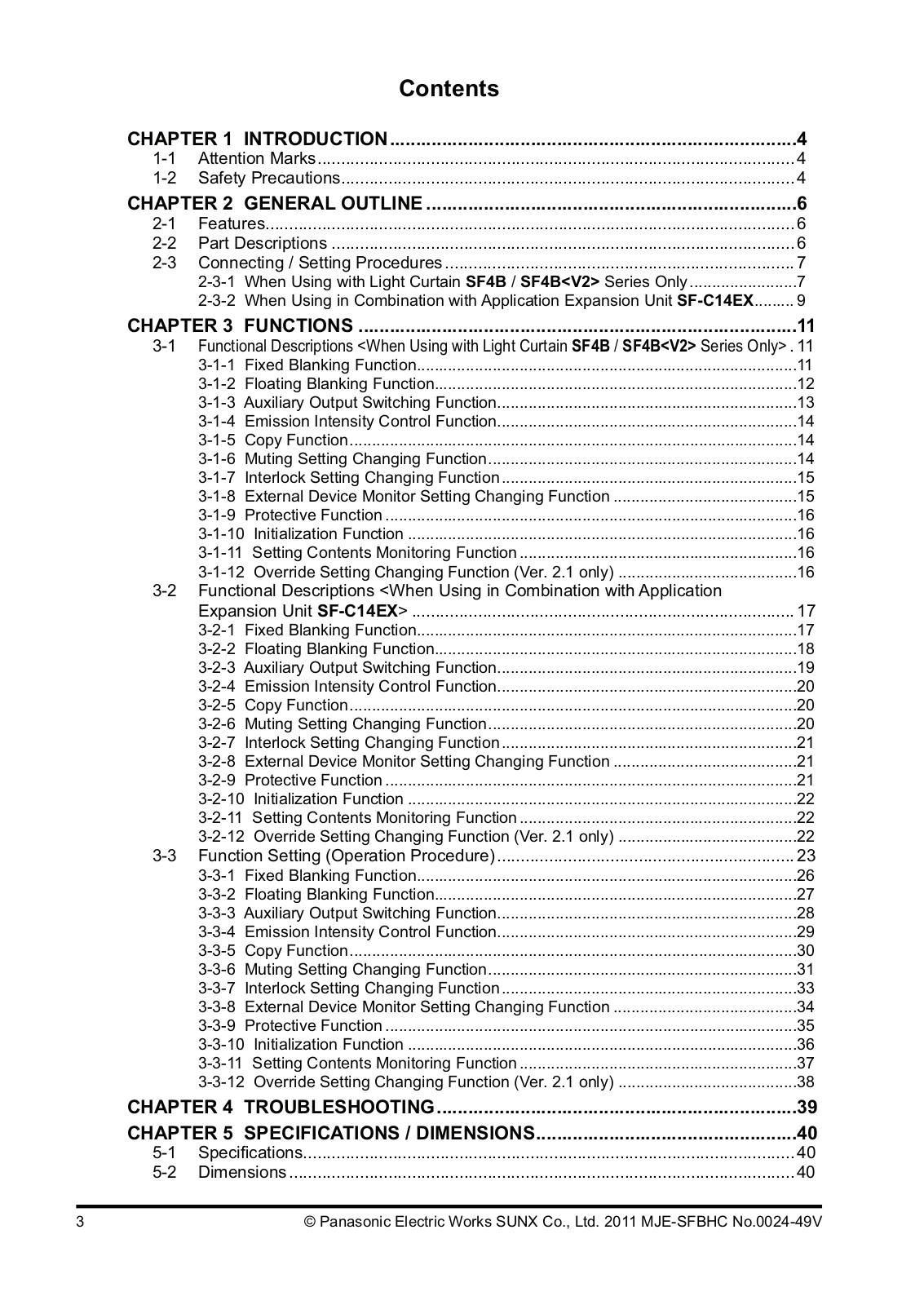
Table of contents
Loading...
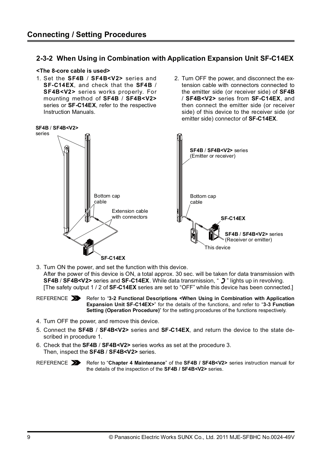
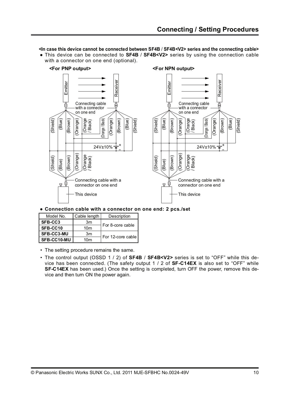
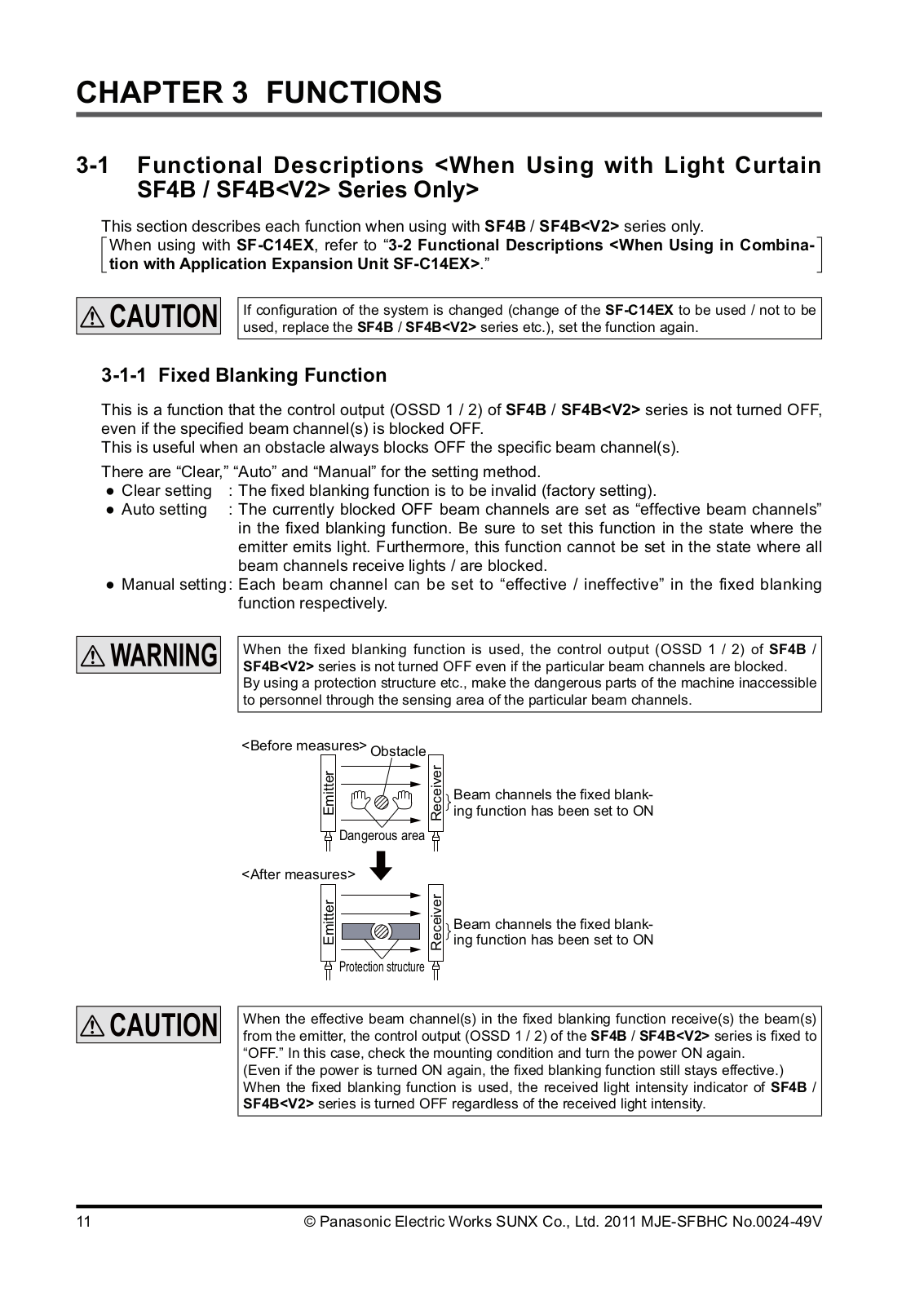
Panasonic SFB-HC Instruction Manual
...
Panasonic Instruction Manual
Download
Specifications and Main Features
Frequently Asked Questions
User Manual
Download
Loading...
+
30
hidden pages
Unhide
You need points to download manuals.
1 point = 1 manual.
You can buy points or you can get point for every manual you upload.
Buy points
Upload your manuals