

Page 1
INSTRUCTION MANUAL
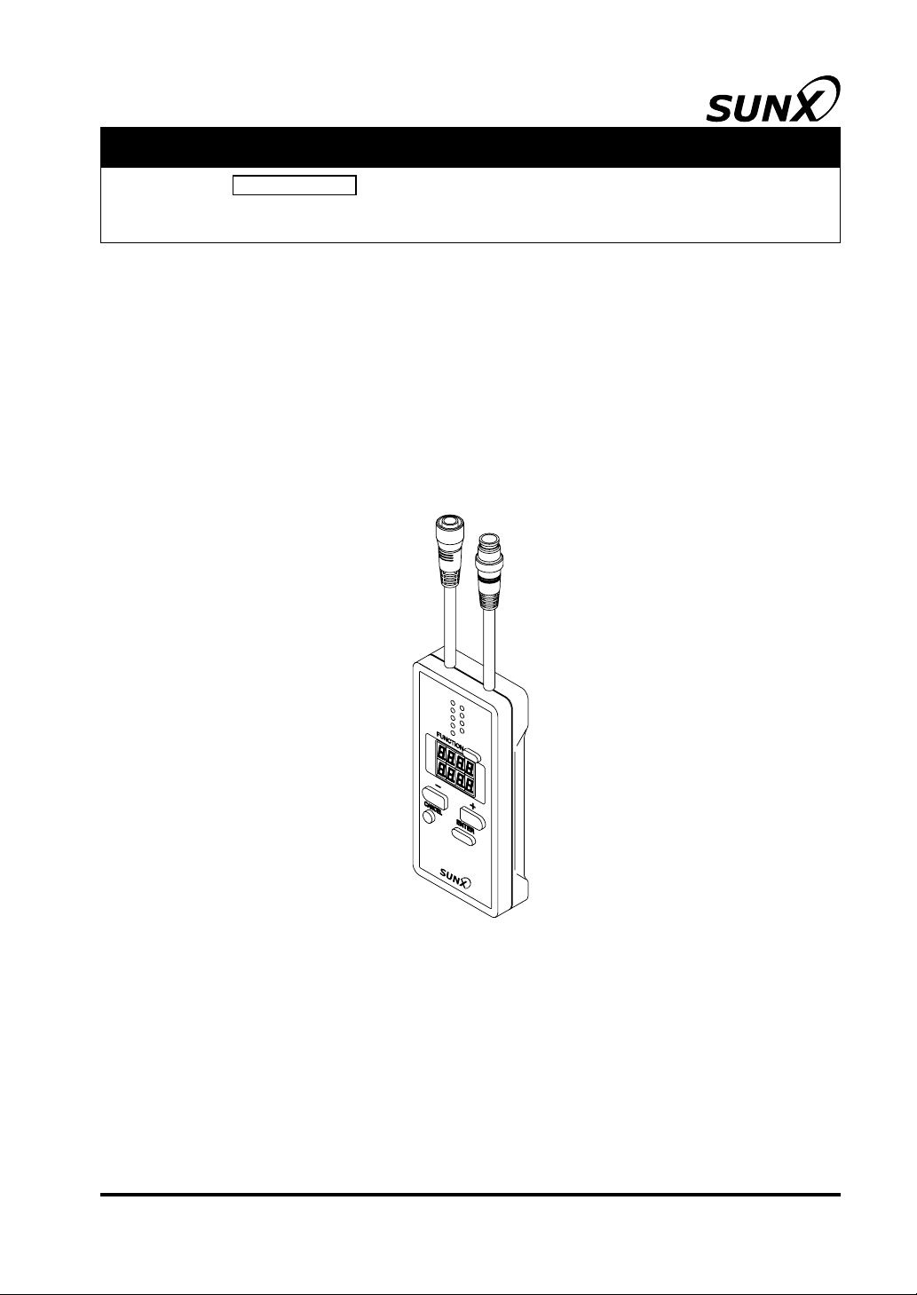
Sensor Option Handy Controller Exclusive for
SFC-HC
SF4C
Series
SUNX Limited MJE-SFCHC No.0013-09V
Page 2

(MEMO)
1 SUNX Limited MJE-SFCHC No.0013-09V
Page 3

Thank you for purchasing SUNX’s Handy Controller
Please read both the instruction manual of this manual and
SFC-HC
exclusive for
SF4C
series carefully and thoroughly for
SF4C
series.
the correct and optimum use of this device.
Kindly keep this manual in a convenient place for quick reference.
This manual has been written for the following personnel who have undergone suitable training and
have knowledge of light curtains, as well as, safety systems and standards (ANSI, etc.).
who are responsible for the introduction of this device
who design a system using this device
who install and connect this device
who manage and operate a plant using this device
NOTICE
1) Drawings in this instruction manual may be little different with actual product. Please be forewarned.
2) The contents of this instruction manual may be changed without prior notice for further improvement of the device.
3) A part of / all of this instruction manual or the software may not be copied without permission
from the publisher.
4) Though we have carefully drawn up the contents of this instruction manual, if there are any
aspects that are not clear, or any error that you may notice, please contact our local SUNX
of ce or the nearest distributor.
5) We shall not be responsible for any consequences of use regardless of the descriptions
above.
6) English and Japanese versions of this instruction manuals are original.
2SUNX Limited MJE-SFCHC No.0013-09V
Page 4

Contents
CHAPTER 1 INTRODUCTION ..............................................................................4
1-1 Attention Marks ..................................................................................................... 4
1-2 Safety Precautions ................................................................................................4
CHAPTER 2 GENERAL OUTLINE .......................................................................6
2-1 Features ................................................................................................................6
2-2 Part Descriptions ..................................................................................................6
2-3 Connecting / Setting Procedures .......................................................................... 7
CHAPTER 3 FUNCTIONS ....................................................................................9
3-1 Functional Descriptions ........................................................................................9
3-1-1 Fixed Blanking Function·····················································································9
3-1-2 Floating Blanking Function·················································································10
3-1-3 Auxiliary Output Switching Function···································································11
3-1-4 Muting Setting Changing Function ·····································································12
3-1-5 Override Setting Changing Function ··································································14
3-1-6 Muting Lamp Diagnosis Function·······································································14
3-1-7 Safety Input Setting Changing Function ····························································14
3-1-8 Large Multi-purpose Indicator Setting Changing Function ·································15
3-1-9 Interlock setting changing function·····································································16
3-1-10 External Device Monitor Setting Changing Function ·······································16
3-1-11 Protective Function ··························································································16
3-1-12
3-1-13 Copy Function (Only for Ver. 2.0 or later of
3-1-14 Initialization Function ·······················································································17
3-2 Function Setting (Operation Procedure) ............................................................... 18
3-2-1 Fixed Blanking Function·····················································································20
3-2-2 Floating Blanking Function·················································································21
3-2-3 Auxiliary Output Switching Function···································································22
3-2-4 Muting Setting Changing Function ·····································································23
3-2-5 Override Setting Changing Function ··································································26
3-2-6 Muting Lamp Diagnosis Function·······································································27
3-2-7 Safety Input Setting Changing Function ····························································28
3-2-8 Large Multi-purpose Indicator Setting changing Function ·································29
3-2-9 Interlock Setting Changing Function ··································································30
3-2-10 External Device Monitor Setting Changing Function ·······································31
3-2-11 Protective Function ··························································································32
3-2-12
3-2-13 Copy Function (Only for Ver. 2.0 or later of
3-2-14 Initialization Function ·······················································································37
Setting Contents Monitoring Function (Only for Ver. 2.0 or later of
SF4C
series)································17
Setting Contents Monitoring Function (Only for Ver. 2.0 or later of
SF4C
series)································35
SF4C
SF4C
series)
series)
···16
···33
CHAPTER 4 TROUBLESHOOTING .....................................................................38
CHAPTER 5 SPECIFICATIONS / DIMENSIONS ..................................................39
5-1 Speci cations........................................................................................................39
5-2 Dimensions ........................................................................................................... 39
3 SUNX Limited MJE-SFCHC No.0013-09V
Page 5
CHAPTER 1 INTRODUCTION
1-1 Attention Marks
This instruction manual employs the following attention marks , depending on the
degree of the danger to call operator’s attention to each particular action. Read the following explanation of these marks thoroughly and observe these notices without fail.
Besides, the attention mark is prepared for the helpful information, detail instruction related to each
part, and reference item or page
If you ignore the advice with this mark, death or serious injury could result.
If you ignore the advice with this mark, injury or material damage could result.
The supplementary content is described with this mark.
REFERENCE The related content is described with this mark.
1-2 Safety Precautions
Use this device as per its speci cations. Do not modify this device since its functions and capabilities may not be maintained and it may malfunction.
This device has been developed / produced for industrial use only.
Before using this device, check whether the device performs properly with the functions and capabilities as per the design speci cations.
In case of disposal, dispose this device as industrial waste.
User in charge
The user in charge has responsible to indicate the person to take the training required for the
safety system, using method, installation, operation, and maintenance.
This device is used and managed by the specialist, never use this device by other operator.
Specialist
A person who is appropriately educated, has widespread knowledge and experience, and
can solve various problems which may arise during work.
Operator
The operator should read this instruction manual thoroughly, understand its contents, and
perform operations following the procedures described in this manual, for the correct operation of this device.
In case this device does not perform properly, the operator should report this to the person in
charge and stop the machine operation immediately. The machine must not be operated until
correct performance of this device has been con rmed.
4SUNX Limited MJE-SFCHC No.0013-09V
Page 6
INTRODUCTION
Fixed blanking function, oating blanking function
With the xed blanking function, this device prevents the person or object from entering into
the dangerous parts of the machine through the invalid sensing area. However, even though
this device can prevent the interference of the person or object into the invalid sensing area
with the xed blanking function, there might exist the more space between the
and already-existence object. Therefore, set the protecting structure so as not to exist any
space in the dangerous sensing area. Detecting human body in the sensing area could result in death or serious injury.
With the oating blanking function, this device changes the size of the minimum sensing object of the
calculate and measure the safety distance again, and check that the device has the wider
space than the safety distance between the dangerous parts of the machine and the sensing
area of the
before its dangerous parts are reached, which can result in death or serious injury.
Set and change the function of the device following the relative laws, regulation, and standard without fail.
Muting setting changing function
The muting setting changing function temporarily invalidates safety function of the connected
devices. Con rm all of the applied laws and standards, and install or operate this device and
peripheral devices correctly. Failure to do so, the operator may suffer a serious injury.
SF4C
seri es that is pre-set the function. When setting or changing the function,
SF4C
series.
If the suf cient distance is not maintained, the machine will not stop
SF4C
series
Environment
Do not use a mobile phone or a radio phone near this device.
Do not use this device in the following environments.
1) Areas with high humidity where condensation is likely to occur
2) Areas exposed to corrosive or explosive gases
3) Areas exposed to vibration or shock of high levels
4) Areas exposed to contact with water
5) Areas exposed to too much steam or dust
Wiring
Be sure to carry out the wiring in the power supply OFF condition.
All electrical wiring should conform to the regional electrical regulations and laws. The wiring
should be done by engineer(s) having the special electrical knowledge.
Do not run the wires together with high-voltage lines or power lines or put them in the same
raceway. This can cause malfunction due to induction.
Maintenance
Clean this device with a clean cloth. Do not use any volatile chemicals.
Other
Never reassemble or remodel this device.
5 SUNX Limited MJE-SFCHC No.0013-09V
Page 7
CHAPTER 2 GENERAL OUTLINE
This chapter gives the system construction, part description, etc. of this device.
2-1 Features
This device is the handy controller for setting each function of the light curtain
series.
Besides, this device performs the checking and copying the setting contents of the function, and protection of writing.
<Functions>
Fixed blanking function
Floating blanking function (Invalid setting of both end beam channels can be set in Ver. 2.1 of
SF4C
series only)
Auxiliary output switching function
Muting setting changing function
(Muting sensor output operation setting can be set in Ver. 2.1 of
Override setting changing function
Muting lamp diagnosis function
SF4C
series only)
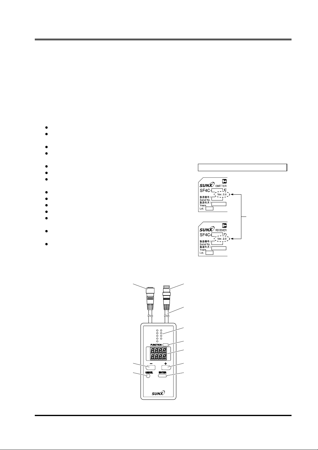
Indicated place of Ver. infomation of
<Plate of emitter side>
SF4C
Safety input setting changing function
(Invalid setting can be set in only Ver. 2.0 or later of
SF4C
series)
Large multi-purpose indicator setting changing function
Interlock setting changing function
External device monitor setting changing function
Protective function
Setting contents monitoring function
(Can be set in only Ver. 2.0 or later of
SF4C
series)
<Plate of receiver side>
For Ver. 2.0 or later
of
SF4C
Not indicated in Ver.
1.0 of
series.
SF4C
Copy function
(Can be set in only Ver. 2.0 or later of
SF4C
series)
Initialization function
2-2 Part Descriptions
SF4C
series
series.
Female connector
- switch
CANCEL switch
Male connector
Cable (0.5m)
FUNCTION indicator × 9
(Green)
FUNCTION switch
Digital display (Red)
+ switch
ENTER switch
6SUNX Limited MJE-SFCHC No.0013-09V
Page 8
Connecting / Setting Procedures
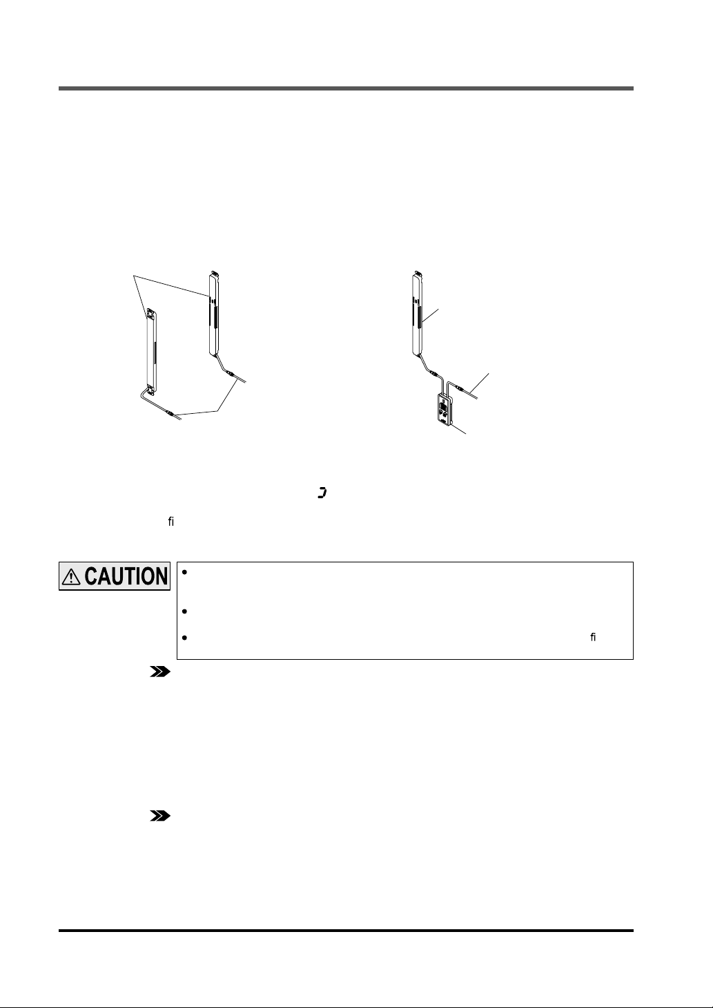
2-3 Connecting / Setting Procedures
This section describes the connecting / setting procedures for both this device and
SF4C
series.
<In case using intermediate connector type to this device>
1. Set the
SF4C
method of
SF4C
series, and check that the
series works properly. For mounting
SF4C
series, refer to the respec-
tive Instruction Manuals.
2. Turn OFF the power, and disconnect the extension cable with connectors connected to
SF4C
series, then connect this device be-
tween emitter (or receiver) of
SF4C
series
and the extension cable with connectors.
SF4C
series
SF4C
series
Emitter (or receiver)
Extension cable
with connectors
To power supply
To power supply
Extension cable
with connectors
This device
3. Turn ON the power, and set the function with this device.
After the power of this device turned ON, approx. 10 sec. will be taken for data transmission with
SF4C
series. While data transmission,
[The control output (OSSD 1 / 2) of
In case of con rming operation of changed setting contents of
the power supply of
SF4C
series once.
“ ”
lights up in revolving.
SF4C
series is set to “OFF” while this device has been connected.]
SF4C
series, turn OFF and turn ON of
In case control is set as shutting OFF power of
when the control output 1 / 2 (OSSD 1 / 2) becomes OFF, supply power from another
power supply.
Do not turns OFF or disconnect wires during setting. in case power is shut OFF during
setting contents, set the contents again after initialization.
When “good” in the check result after changing setting is displayed, the setting is xed. In
case the “good” is not displayed, set the setting contents again.
REFERENCE Refer to “
Function Setting (Operation Procedure)
respectively.
3-1 Functional Descriptions
4. Turn OFF the power of emitter and receiver of
5. Connect both
SF4C
series and the extension cable with connectors and return the device to the
” for the details of the functions, and refer to “
SF4C
series, then remove this device.
SF4C
series from the power supplely
” for the setting procedures of the functions
3-2
state described in procedure 1.
6. Turn ON the power of emitter and receiver of
SF4C
series, and check that the
SF4C
series works
as set at the procedure 3.
Then, inspect the
REFERENCE Refer to “
7 SUNX Limited MJE-SFCHC No.0013-09V
SF4C
series.
inspection of the
Chapter 4 Maintenance
SF4C
series.
” of the
SF4C
series instruction manual for the details of the
Page 9
Connecting / Setting Procedures
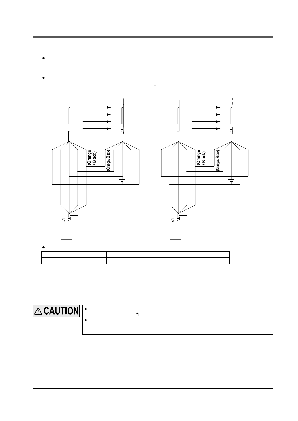
<In case using this device with cable type of SF4C series>
Wire a discrete connection cable with connector on one end
And wire a clip of the discrete connection cable with connector on one end to a lead wire of cable
type of
SF4C
series.
It is also possible to use in condition that an intermediate connector type of
to a cable with connector on one end
SFB-CC -MU
(optional).
<For PNP output> <For NPN output>
SFC-WNC1
(optional) to this device.
SF4C
series is wired
Emitter
(Shield)
(Blue)
(Brown)
(Orange)
24V±10% 24V±10%
(Blue)
(Brown)
(Orange)
(Orange
/ Black)
Connection cable with a
connector on one end
This device This device
Receiver
(Orange)
Emitter Receiver
(Blue)
(Shield)
(Brown)
+
-
(Blue)
(Shield)
(Brown)
(Orange)
(Blue)
(Brown)
(Orange)
(Orange
/ Black)
Connection cable with a
connector on one end
(Blue)
(Shield)
(Brown)
(Orange)
+
-
Connection cable with a connector on one end: 1 pc./set
Model No. Cable length Description
SFC-WNC1
The setting procedure remains the same.
•
The control output (OSSD 1 / 2) of
•
3m Cable which incorporates clips on end of the discrete wire.
SF4C
series is set to “OFF” while this device has been connected. Once the setting is completed, turn OFF the power, remove this device and then turn ON
the power again.
When the lead wire contacts with other lead wires, maximally 26.4V DC of voltage is applied and 3A of current ows.
In case the connecting cable with connector on one end connected the cable type of
SF4C series or the intermediate connector type to this device, lead wire may be disconnected. Be sure the lead wire is not disconnected.
8SUNX Limited MJE-SFCHC No.0013-09V
Page 10
CHAPTER 3 FUNCTIONS
3-1 Functional Descriptions
If con guration of the system is changed (replace the
again.
SF4C
series etc.), set the function
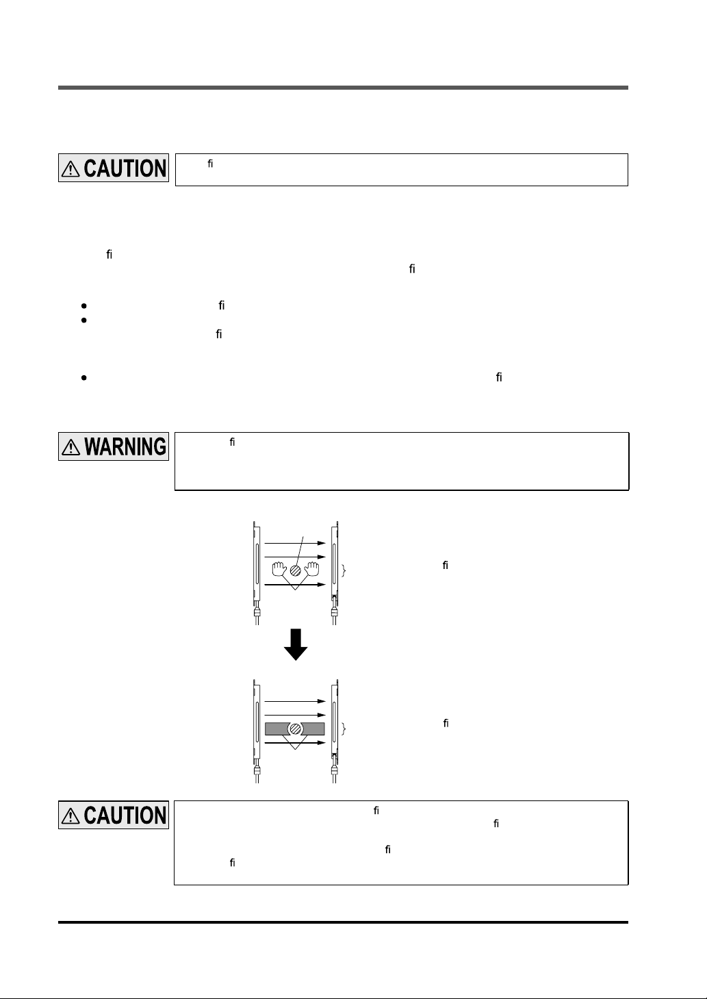
3-1-1 Fixed Blanking Function
This is a function that the control output (OSSD 1 / 2) of
speci ed beam channel(s) is blocked OFF.
This is useful when an obstacle always blocks OFF the speci c beam channel(s).
There are “Clear,” “Auto” and “Manual” for the setting method.
Clear setting : The xed blanking function is to be invalid (factory setting).
Auto setting : The currently blocked OFF beam channels are set as “valid beam channels” in
the xed blanking function. Be sure to set this function in the state where the
emitter emits light. Furthermore, this function cannot be set in the state where
all beam channels receive lights / are blocked.
Manual setting : Each beam channel can be set to “valid / invalid” in the xed blanking function
respectively.
The all light beam channel can not be selected all valid / all invalid
When the xed blanking function is used, the control output (OSSD 1 / 2) of
not turned OFF even if the particular beam channels are blocked.
By using a protection structure etc., make the dangerous parts of the machine inaccessible
to personnel through the sensing area of the particular beam channels.
<Before measures>
Emitter Receiver
Obstacle
SF4C
series is not turned OFF, even if the
SF4C
series is
Beam channels the xed blanking function has been set to ON
Dangerous area
<After measures>
9 SUNX Limited MJE-SFCHC No.0013-09V
Emitter Receiver
Beam channels the xed blanking function has been set to ON
Protection structure
When the valid beam channel(s) in the xed blanking function receive(s) the beam(s) from
the emitter, the control output (OSSD 1 / 2) of the
check the mounting condition and turn the power ON again.
(Even if the power is turned ON again, the xed blanking function still stays valid.)
When the xed blanking function is used, the received light intensity indicator of
ries is turned OFF regardless of the received light intensity.
SF4C
series is xed to “OFF.” In this case,
SF4C
se-
Page 11
Functional Descriptions
3-1-2 Floating Blanking Function
If the number of the blocked beam channels is less than the set number of the beam channels, the
control output (OSSD 1 / 2) of
This function is useful when an obstacle moves within the sensing area.
The factory setting of this function is “invalid.”
The following items can be set.
Set number of beam channels
Selectable among 0 (the oating blanking function is invalid), 1, 2 or 3.
Invalid setting of both end beam channels (only for Ver. 2.1 of SF4C series)
Be able to select valid or invalid of oating blanking function in both ends of beam channels.
SET (Valid) : The
•
•
CLR (Invalid) : The oating blanking function becomes effective for all beam channels includ-
Non-serial beam channel setting
•
SET (Valid) :
•
CLR (Invalid) : When the beam channels are blocked discontinuously even in the set beam
SF4C
series is not turned “OFF.”
oating blanking function becomes invalid at both ends of beam channels. In
case either end of the beam channel is blocked, the control output (OSSD 1 / 2) of
SF4C
series is turned “OFF” regardless of the set number of the beam channels.
ing both end beam channels.
Even if the beam channels are blocked discontinuously in the set beam channels,
the control output (OSSD 1 / 2) of
channels, the control output (OSSD 1 / 2) of
SF4C
series is turned “ON.” (Discontinuous mode)
SF4C
series is turned “OFF.”
(Continuous mode)
When using the oating blanking function, the size of the minimum sensing object becomes larger, and the safety distance is longer as well. For the calculation of the safety
distance, refer to the instruction manual enclosed with
Before designing the system, refer to the relevant laws and standards of the region
where
SF4C
The minimum sensing object differs depending on the set number of the beam channels.
series is to be used and then install
SF4C
SF4C
series.
series.
[For use in Europe (EU) (as EN 999)] (Also applicable to ISO 13855 / JIS B 9715)
(For intrusion direction perpendicular to the sensing area)
<In case that the minimum sensing object is over ø40mm>
Equation S = K × T + C
S : Safety distance (mm)
Minimum required distance between the sensing area surface and the dangerous parts of
the machine.
K : Intrusion velocity of operator’s body or object (mm/sec.)
Taken as 1,600 (mm/sec.) for calculation
T : Response time of total equipment (sec.)
T = T
m
+ T
SF4C
Tm: Maximum halting time of machine (sec.)
T
: Response time of
SF4C
SF4C
series (sec.)
C : Additional distance (mm)
C = 850 (mm)
<Minimum sensing object>
Floating blanking function
Val id
SF4C-H
,
SF4C-H -J05
Invalid
ø25mm ø45mm ø65mm ø85mm
1 beam channel 2 beam channels 3 beam channels
If the oating blanking function is used, the incident light intensity indicator is turned OFF
when an obstacle exists in the sensing range regardless of the incident light intensity.
10SUNX Limited MJE-SFCHC No.0013-09V
Page 12
Functional Descriptions
3-1-3 Auxiliary Output Switching Function
This function changes the operation state of the auxiliary output. It is useful when desired to make an
indicator to operate or inform the operation state of the
The auxiliary output is a non-safety output. Therefore, do not use the auxiliary output for the
purpose of stopping the machine that the
result in death or serious injury.
The following settings are selectable.
Operation of the auxiliary output corresponding to
Setting
mode
Auxiliary output setting
Negative logic of the control
0
output (OSSD 1 / 2)
(factory setting)
Positive logic of the control
1
output (OSSD 1 / 2)
2 OFF when test output is valid OFF ON
3 ON when test output is invalid ON OFF
OFF under unstable light
4
receiving condition (Note 1)
ON under unstable light
5
receiving condition (Note 1)
6 ON during muting OFF
7 OFF during muting ON
ON in light receiving condition
8
(Note 2)
OFF in light receiving condition
9
(Note 2)
10 ON during safety input valid
11 OFF during safety input valid
12 OFF during lockout
13 ON during lockout
Notes: 1) When the xed blanking function, the oating blanking function or the muting function is used, the setting of ON / OFF
2) By the setting of ON / OFF in light receiving condition, light-receiving / light interrupted condition is output regardless of
<e.g.>
When the xed blanking function is used, if an obstacle exists in the set area and other area is in light receiving condi-
3) The state of the auxiliary output remains the same even if the
under unstable light-receiving condition does not work.
the xed blanking function, the oating blanking function or the muting function.
tion, the control output (OSSD 1 / 2) is in ON sate, however, the auxiliary output becomes OFF since the
has been detecting the obstacle.
When
test
input is
valid
Unstable
light-receiving
condition
ON
OFF
(Note 3) OFF ON (Note 3)
(Note 3) ON OFF (Note 3)
-
-
-- -
-- -
-- --
-- --
SF4C
series to PLC.
SF4C
series is installed. Failure to do so could
SF4C
series state
State of sensing area when test input is invalid
Unshielded
Others
Shielded
When
safety
input is
valid
OFF when OSSD is ON
ON when OSSD is OFF
ON when OSSD is ON
OFF when OSSD is OFF
ON during muting
Others: OFF
OFF during muting
Others: ON
ON OFF
OFF ON
ON
OFF
SF4C
series state changes.
-
-
--
--
-
-
-
-
-
-
SF4C
Lockout
ON
OFF
(Note 3)
(Note 3)
OFF
ON
OFF
ON
-
-
OFF
ON
series
11 SUNX Limited MJE-SFCHC No.0013-09V
Page 13

Functional Descriptions
3-1-4 Muting Setting Changing Function
The setting of the muting function can be changed.
Setting of the muting function on each beam channel
Each beam channel can be set to “valid / invalid” in the muting function respectively. (Note)
All beam channel can not be all invalid.
The factory setting of this function is valid for all beam channels.
Note: If the beam channel set to invalid in the muting function is blocked, the control output (OSSD 1 / 2) becomes “OFF” and the
muting function is canceled.
There are two setting methods, “Auto” and “Manual” to set muting beam channel.
Auto setting : The beam channel which is currently blocked is set as the “valid” beam chan-
•
nel. When all beam channels are in light receiving condition, the setting is not
accepted. Furthermore, in the state that all beam channels are blocked, the all
beam channels become “valid” in the muting function.
Manual setting : Each beam channel can be set to “valid / invalid” in the muting function.
•
ON: The muting function is valid
OFF: The muting function is invalid
Muting maximum continuous valid time setting
Maximum continuous valid time setting for muting function can be changed.
The maximum continuous valid time is 1 to 600 sec. (1 sec. unit) or no limit.
Muting sensor output operation setting (only for Ver. 2.1 of SF4C series)
Output operation of muting sensor can be selected
Factory setting is NONO (Normally Open • Normally Open)
NONO (Normally Open, Normally Open)
•
A muting sensor which is to be connected to the muting input 1
(ON with light non-received status, ON with object approaching status and ON with object contacted status)
A muting sensor which is to be connected to the muting input 2
(ON with light non-received status, ON with object approaching status and ON with object contacted status)
NONC (Normally Open, Normally Close)
•
A muting sensor which is to be connected to the muting input 1
(ON with light non-received status, ON with object approaching status and ON with object contacted status)
A muting sensor which is to be connected to the muting input 2
(ON with light received status, ON with object non-approaching status and ON with object non-contacted status)
Muting function only for the sensing object exit
Muting function only for the sensing object exit can be set.
When setting to the muting function only for the sensing object exit, install the muting sensor only
in the dangerous zone and the installation in the safety zone is not required.
Using conditions of the muting function only for the sensing object exit is as follows.
The sensing object should move to one side.
•
(The sensing object should move from the dangerous zone to the safety zone.)
The sensing object should pass through the sensing area within 4 sec. after the muting sensor
•
turns OFF. (Note)
Note: Muting time only for the sensing object exit can be set between 0 (Invalid) to 4,000ms (Unit: 100ms).
In case using the muting function only for the sensing object exit and the oating blanking
function, set by being sure listed below.
The set beam channel number of the oating blanking function is 0 or 1 beam channel
only.
In case making valid the invalid setting of both end beam channels of the oating blanking function, set invalid the muting function of both ends of beam channels in each beam
channel setting of muting function.
12SUNX Limited MJE-SFCHC No.0013-09V
Page 14
Functional Descriptions
Installation condition example of muting sensors when setting the muting function
only for the sensing object exit
Muting sensor B
Muting sensor A
Guard
S (m/sec.)
Sensing object
Guard
1
2
Safety zone Dangerous zone
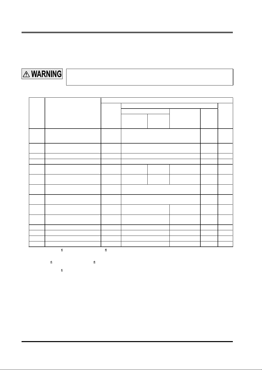
1. The time of the sensing object to be passed through the muting sensors A to B shall be 0.03 to under 3 sec.
Distance between A and B (m) < S (m/sec.) × 3 (sec.)
S: The moving speed (m/sec.) of the sensing object
2. The time of the sensing object to be passed through the muting sensor A to the light curtain shall be under 4
sec.
Distance between muting sensor A and the light curtain (m) < S (m/sec.) × 4 (sec.)
Distance between muting sensor A and the light curtain (m) < Total length of the sensing object (m)
S: The moving speed (m/sec.) of the sensing object
3. The time of the sensing object to be passed through the light curtain to the end of guard zone shall be under
4 sec.
Distance between the light curtain and the end of guard zone (m) < S (m/sec.) × 4 (sec.) - 0.2
S: The moving speed (m/sec.) of the sensing object
Note: If a beam channel whose muting function is set to be invalid is blocked during the muting, the control output (OSSD 1 / 2)
will be turned OFF and the muting function will be released.
Muting input conditions
The order for inputting the muting input 1 and 2, which the muting function activates, can be set.
1 = 2: Valid even either muting input 1 or muting input 2 comes rst
1 2: Valid only when the muting input 1 comes rst
2 1: Valid only when the muting input 2 comes rst
Note: The setting is possible for each beam channel.
Light curtain
3
Combination of using muting input conditions and setting of each beam channel of the muting
function allows to set making muting function valid when muting input conditions are 1 to 2 or 2
to 1.
The setting method is to set the each beam channel setting of muting input condition 1 to 2 and
set the each beam channel setting of muting input condition 2 to 1.
13 SUNX Limited MJE-SFCHC No.0013-09V
Page 15

Functional Descriptions
3-1-5 Override Setting Changing Function
Maximum continuous valid time set at the override function can be changed.
The maximum continuous valid time can be set in the range of 1 to 600 sec. (in units of 1 sec.).
The factory setting is 60 sec.
3-1-6 Muting Lamp Diagnosis Function
The muting lamp diagnosis function can be set to “valid / invalid.” (Note)
The factory setting of this function is valid.
ON : The muting lamp diagnosis function is valid.
OFF : The muting lamp diagnosis function is invalid.
Note: If the muting lamp diagnosis function is set to invalid, the muting function is maintained even if the lamp blew.
3-1-7 Safety Input Setting Changing Function
This function enables to select the safety contacting point input mode or the safety sensor input mode
with this controller. Furthermore, safety input can be set to invalid for Ver. 2.0 or later of
Safety contacting point input mode
A safety contacting point can be connected. It is at the time of factory setting
Safety sensor input mode
A safety sensor can be connected.
<Output operations of a safety contacting point and a safety sensor>
NC (Normally Closed) type Operation at ON state
Safety contacting point
Safety
sensor
Note: the safety contacting point which is connected to the safety input 1 / 2 or safety sensor and control out-
put of
ON with object non-contacted status
(Emergency stop switch, etc.)
ON with light received status (Light
curtain, etc.)
ON with object non-approaching
status (Safety switch, etc.)
SF4C
series should be kept OFF.
PNP output: Connect to +V
NPN output: Connect to 0V
Invalid (only for Ver. 2.0 or later of SF4C series)
Safety input can be invalid. In this case, safety contact point and safety sensor cannot be connected.
SF4C
series.
Operation at OFF state
Open (Note)
Use 0.2mm2 or more shielded cable when connecting other
safety input 1 / 2.
When extending the cable of other
use the exclusive cable and the total cable length should be 40.5m or less (for each emitter / receiver). If the total cable length is exceeding 40.5m, the device may malfunction,
resulting in death or serious injury.
Response time of safety sensor is sum of a response time of this device and safety sensor itself.
SF4C
series
Control output 1
(OSSD 1)
Control output 2
(OSSD 2)
SF4C
series which is connected to the safety input 1 / 2,
Safety sensor
Response time of
7ms
Response time of safety sensor
<Ex.>
In case of using
Response time of safety sensor + response time of
= 7ms + 7ms = 14ms
SF4C
series cable to the
SF4C
series
SF4C
as safety sensor.
SF4C
series
14SUNX Limited MJE-SFCHC No.0013-09V
Page 16

Functional Descriptions
When using the device in PNP output (or NPN output), use PNP output (or NPN output)
safety sensor. The control output (OSSD 1 / 2) becomes OFF by using wrong output type
of sensor.
Series connection is also available when connecting other
put 1 / 2. However, this device does not incorporate the interference prevention function.
Thus, take suf cient care when installing the devices.
Use a safety sensor which incorporates a crossover short-circuit function in the control
output and connect both the safety input 1 wire (gray) and the safety input 2 wire (gray /
black). Take care that if only one wire is connected, the device may not operate normally.
Use a safety contacting point which incorporates two NC (Normally Closed) contacting
points and connect both the safety input 1 wire (gray) and the safety input 2 wire (gray /
black). Take care that if only one wire is connected, the device may not operate normally.
In case setting the safety contacting point input mode or the safety sensor input mode,
connect to +V or 0V as a following table when safety input function is not used.
Safety input
setting changing function
Safety contacting point
input mode
Safety sensor
input mode
SF4C
series to the safety in-
For PNP output For NPN output
Safety input 1 wire
(gray)
Connect to +V Connect to 0V Connect to +V Connect to 0V
Connect to +V Connect to +V Connect to 0V Connect to 0V
Safety input 2 wire
(gray / black)
Safety input 1 wire
(gray)
Safety input 2 wire
(gray / black)
3-1-8
Large Multi-purpose Indicator Setting Changing Function
One mode can be selected from the following 8 modes
Factory setting is mode 0.
Operation of large multi-purpose indicator
Mode
(Note 1)
(Note 1)
(Note 1)
(Note 1)
Notes: 1) Blinking takes precedence in case of same color brinks or light up in the large multi-purpose indicator.
2) The large multi-purpose indicator (red) and the large multi-purpose indicator (green) can be lit up and blinked in same
Large multi-purpose
indicator input 1
PNP output:
High
0 Lights up in red Lights up in green
1 Blinks in red Blinks in green
2 Lights up in red Blinks in green
3 Blinks in red Lights up in green
4
5
6
7
Lights up in red Blinks in red
Lights up in red Blinks in red
time.
NPN output:
Low
Blinks in green Lights up in green
--
Large multi-purpose
indicator input 2
PNP output:
Low
NPN output
High
Control output 1 / 2
(OSSD 1 / 2)
ON OFF Valid Valid
----
----
----
----
----
----
Lights up
in green
--
Lights up
in red
Muting
function
Blinks in
green
Lights up
in green
Override
function
Blinks in
green
-
Furthermore, large multi-purpose indicator (red) can be blinked in lockout status.
Lockout blinking display function Lockout ON
Valid Blinks in red
Invalid
-
15 SUNX Limited MJE-SFCHC No.0013-09V
Page 17

Functional Descriptions
3-1-9 Interlock setting changing function
It is selectable one interlock state among the following three interlock settings (Mode 3)
•
Start / Restart interlock (Mode 0)
SF4C
series goes into the interlock state after the power is turned ON, or when the light of
SF4C
series is blocked.
The factory setting is start / restart interlock.
•
Start interlock (Mode 1)
SF4C
series goes into the interlock state when the power supply is turned ON. Once this inter-
lock is reset, the device does not go into the interlock state.
Restart interlock (Mode 2)
•
SF4C
series does not go into the interlock state when turning ON the power supply. Only when
the control output (OSSD 1 / 2) becomes ON and the light for
is turned ON and this device receives the light, the device goes into the interlock state.
3-1-10 External Device Monitor Setting Changing Function
The setting of the external device monitor can be changed
1. Allowable time for response time: 100 to 600ms (Unit: 10ms)
Factory setting is 300ms.
2. The external device monitor function can be selected to valid or invalid
The factory setting is set to valid for the external device monitor function.
3-1-11 Protective Function
SF4C
is blocked after the power
The functional settings are not allowed to change without the input of a password of
When the protective function is set to “valid,” the setting can be changed by inputting the password.
The setting contents monitor function can be used regardless of the protective function “valid / invalid.”
The password should be a 4-digit number from 0 to 9. (The password of the factory setting is “0000.”)
The protective function is set on the receiver.
When the protecting function is set to “invalid,” the third person may change the setting. It is recommended that the protecting function should be set to “valid” so as not to
change the setting by the third person.
Take sufficient care not to forget the set password. In case you forget the password,
please contact us.
SF4C
series.
3-1-12 Setting Contents Monitoring Function (Only for Ver. 2.0 or later of SF4C series)
Each setting of the
Setting of the xed blanking function (Reading out the record of the latest 5 times is possible)
Setting of the oating blanking function (Reading out the record of the latest 5 times is possible)
Setting of the auxiliary output switching function
Setting of the muting setting changing function
(Reading out the record of the latest 5 times is possible, however, only for setting beam channel.)
Setting of the override setting changing function
Setting of the muting lamp diagnosis function
Setting of the safety input setting changing function
Setting of the large multi-purpose indicator setting changing function
Setting of the interlock setting changing function
Setting of the external device monitor setting changing function
Setting of the protect function
Model No. / the number of beam channels of
SF4C
series can be monitored. The following can be monitored.
SF4C
series.
16SUNX Limited MJE-SFCHC No.0013-09V
Page 18

Functional Descriptions
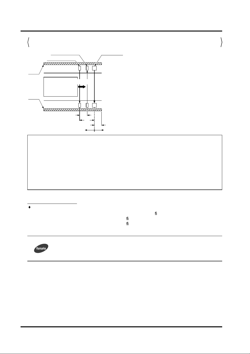
3-1-13 Copy Function (Only for Ver. 2.0 or later of SF4C series)
This is a function to copy the setting of a
SF4C
series to other
SF4C
series.
This function is available only under the same system con guration (the number of beam channels,
same model No.).
All functions that can be set with this device can be copied.
Note that the password is also copied with this function.
The following operations are available with this function.
Upload : Upload the functional setting data of
Download : Download the functional setting data of this device to
SF4C
series to this device.
SF4C
series.
Monitoring : Check the functional setting data saved in this device.
SF4C
Original
Upload Download
(Storage area for
series
This device
SF4C
series)
SF4C
Copied
series
3-1-14 Initialization Function
The settings of
The factory setting of each function is as follows.
Fixed blanking function Invalid
Floating blanking function Invalid
Auxiliary output switching function Mode 0 [Negative logic of control output (OSSD 1 / 2)]
Muting setting changing
function
Override setting changing
function
Muting lamp diagnosis function Invalid
Safety input setting
changing function
Large multi-purpose
indicator setting changing
function
Interlock setting changing function Mode 0 (Start / restart interlock function is valid)
External device monitor
setting changing function
Protective function
(Note1)
Notes: 1) Protective function in Ver. 2.1 of
2) Setting data of copy function is not initialized.
SF4C
series can be initialized. (factory setting) (Note)
Function Setting
Muting sensor output
operation setting
Maximum continuous valid
time
Muting function only for the
sensing object exit
Muting input conditions 1 = 2
Select beam channel All beam channels
Select function Valid
Maximum continuous valid
time
Select function Valid
Select input mode Safety contacting point input mode
Select mode
Lockout blinking display function
Select function Valid
Time setting 300ms
Password 0000
Select function Invalid
SF4C
series is not initialized.
NONO (Normally Open, Normally Open)
No limit
Invalid
60 sec.
Mode 0 (Lights up in red when the large multipurpose indicator input 1 is ON, Lights up in green
when the large indicator input 2 is ON)
Invalid
17 SUNX Limited MJE-SFCHC No.0013-09V
Page 19

3-2 Function Setting (Operation Procedure)
This section describes the setting of each function (operation procedure).
<Selecting the setting item>
Select a setting item with FUNCTION or CANCEL switch, and con rm it with ENTER.
key operation
To “
3-2-1 Fixed Blanking Function
3-2-2 Floating Blanking Function
To “
To “
3-2-3 Auxiliary Output Switching Function
”
”
”
Function Setting
: FUNCTION
: ENTER
: CANCEL
: : +
3-2-4 Muting Setting Changing Function
To “
3-2-5 Override Setting Changing Function
To “
To “
3-2-6 Muting Lamp Diagnosis Function
3-2-7 Safety Input Setting Changing Function
To “
3-2-8 Large Multi-purpose Setting Indicator Changing Function
To “
3-2-9 Interlock Setting Changing Function
To “
To “
3-2-10 External Device Monitor Setting Changing Function
To “
3-2-11 Protect Function
To “
3-2-12 Setting Contents Monitoring Function
3-2-13 Copy Function
To “
”
” (Only for Ver. 2.0 or later of
”
”
”
”
”
” (Only for Ver. 2.0 or later of
”
”
SF4C series
SF4C
)
series)
To “
3-2-14 Initialization Function
”
18SUNX Limited MJE-SFCHC No.0013-09V
Page 20

Function Setting
<Inputting a password>
The procedure for inputting a password is as follows.
Input password
NG
CH1
Complete inputting password
1) “
3-2-12 Setting Contents Monitoring Function
2) Once the password is input, you do not need to input the password again till the power is
turned OFF. (Except “
without changing the protective function to invalid, the password have to be input again since
the protective function is still valid.
3-2-11 Protective Function
” is not “locked.”
”) However, if the power is turned ON again
19 SUNX Limited MJE-SFCHC No.0013-09V
Page 21

3-2-1 Fixed Blanking Function
Function Setting
: ENTER
: FUNCTION
: CANCEL
: -
Key operation
: +
20SUNX Limited MJE-SFCHC No.0013-09V
Page 22

Function Setting
3-2-2 Floating Blanking Function
: FUNCTION
: ENTER
: CANCEL
: -
: +
Key operation
21 SUNX Limited MJE-SFCHC No.0013-09V
Page 23

3-2-3 Auxiliary Output Switching Function
Key operation
: FUNCTION
: ENTER
: CANCEL
: -
Function Setting
: +
22SUNX Limited MJE-SFCHC No.0013-09V
Page 24

Function Setting
3-2-4 Muting Setting Changing Function
23 SUNX Limited MJE-SFCHC No.0013-09V
Page 25

Function Setting
24SUNX Limited MJE-SFCHC No.0013-09V
Page 26

Function Setting
: ENTER
: FUNCTION
: CANCEL
: -
: +
Key operation
25 SUNX Limited MJE-SFCHC No.0013-09V
Page 27

3-2-5 Override Setting Changing Function
Key operation
: FUNCTION
: ENTER
: CANCEL
: -
Function Setting
: +
26SUNX Limited MJE-SFCHC No.0013-09V
Page 28

Function Setting
3-2-6 Muting Lamp Diagnosis Function
: FUNCTION
: ENTER
: CANCEL
: -
: +
Key operation
27 SUNX Limited MJE-SFCHC No.0013-09V
Page 29

3-2-7 Safety Input Setting Changing Function
: FUNCTION
: ENTER
: CANCEL
: -
Key operation
Function Setting
: +
28SUNX Limited MJE-SFCHC No.0013-09V
Page 30

Function Setting
3-2-8 Large Multi-purpose Indicator Setting changing Function
: FUNCTION
: ENTER
: CANCEL
: -
: +
Key operation
29 SUNX Limited MJE-SFCHC No.0013-09V
Page 31

3-2-9 Interlock Setting Changing Function
: FUNCTION
Key operation
: ENTER
: CANCEL
: -
Function Setting
: +
30SUNX Limited MJE-SFCHC No.0013-09V
Page 32

Function Setting
3-2-10 External Device Monitor Setting Changing Function
: FUNCTION
: ENTER
: CANCEL
: -
: +
Key operation
31 SUNX Limited MJE-SFCHC No.0013-09V
Page 33

3-2-11 Protective Function
Function Setting
: FUNCTION
: ENTER
: CANCEL
: -
: +
Key operation
32SUNX Limited MJE-SFCHC No.0013-09V
Page 34

Function Setting
3-2-12 Setting Contents Monitoring Function (Only for Ver. 2.0 or later of SF4C series)
33 SUNX Limited MJE-SFCHC No.0013-09V
Page 35

Function Setting
: ENTER
: FUNCTION
: CANCEL
: -
Key operation
: +
34SUNX Limited MJE-SFCHC No.0013-09V
Page 36

Function Setting
3-2-13 Copy Function (Only for Ver. 2.0 or later of SF4C series)
35 SUNX Limited MJE-SFCHC No.0013-09V
Page 37

Function Setting
: FUNCTION
: ENTER
: CANCEL
: -
: +
Key operation
36SUNX Limited MJE-SFCHC No.0013-09V
Page 38

Function Setting
3-2-14 Initialization Function
NONO (Normally Open, Normally Open)
No limit
Invalid
Muting function only for the
sensing object exit
Muting input conditions 1 = 2
Function Set contents
: ENTER
: FUNCTION
: CANCEL
: -
: +
Fixed blanking function Invalid
Floating blanking function Invalid
Key operation
Auxiliary output switching function Mode 0 [Negative logic of control output (OSSD 1 / 2)]
Muting setting changing function
Select beam channel All beam channels
Select function Valid
Override setting changing function
60 sec.
Muting lamp diagnosis function Invalid
Select function Valid
Safety input setting changing
Select input mode Safety contacting point input mode
function
Select mode
Large multi purpose input function
Invalid
Select function Valid
Time setting 300ms
Password 0000
Select function Invalid
changing function
Interlock setting changing function
External device monitor setting
changing function
Protective function (Note)
Note:
37 SUNX Limited MJE-SFCHC No.0013-09V
Page 39

CHAPTER 4 TROUBLESHOOTING
Symptoms Cause Remedy
Control output (OSSD
1 / 2) is not turned ON.
The settings are not
changed
Lighting up fault
indicator [FAULT] of
SF4C
series
Light up all indicators
of
SF4C
series
Sequentially light up
all indicators of
series
Lost a password
Error indication Cause Remedy
Note: The factory setting of the
This device is connected to the
series.
Turning the power OFF and ON is not
done
Disconnection, cutting down power and so on
SF4C
SF4C
-
series
series
EEPROM error in
(Data error of EEPROM)
EEPROM error in
(Data error of EEPROM)
SF4C
The fixed blanking function is set in all
lights received / all lights blocked condition, or the muting function is set in all
lights received condition.
The copy function is used for the units
having different system con guration.
In the copy function, download the data
without uploading or select monitor of
copy function.
The password does not match.
Sensor communication error 1
(Model No. is wrong)
Sensor communication error 2
Wrong wiring between the emitter and
receiver.
Disconnection, cutting down power and so on
Sensor communication error 3
Effect from noise or failure of internal
circuit
Failure of EEPROM in this device.
(Failure on device)
Failure of EEPROM in this device.
(Failure on EEPROM data)
SF4C
series password is “0000.”
SF4C
Disconnect this device.
Remove the device from
Turn the power OFF and ON again.
After initialization, set again.
After initialization, set again.
Contact our of ce.
Contact our of ce.
Do not set the xed blanking function in all
lights received / all lights blocked condition,
or the muting function in all lights received
condition.
Use the copy function for the units having
identical system con guration.
Upload the data before downloading or select monitor of copy function.
Input the correct password. In case you forget the password, Contact our of ce. (Note)
Connect this device to
Connect the emitter and receiver correctly.
After initialization, set again
Check the noise state around the
series.
Contact our of ce..
Contact our of ce..
SF4C
SF4C
series.
series and
SF4C
If the device does not work correctly after checking the items above, please consult us.
38SUNX Limited MJE-SFCHC No.0013-09V
Page 40

CHAPTER 5 SPECIFICATIONS / DIMENSIONS
5-1 Speci cations
Model No.
Item
Applicable model Light curtain
Supply voltage 24V DC±10% Ripple P-P 10% or less (common to sensor power supply)
Current consumption
Communication method
Digital display 4-digit red LED display × 2 (selected beam channels, setting contents etc. are displayed.)
FUNCTION indicator
Fixed blanking function, Floating blanking function, Auxiliary output switching function
Functions
Protection IP40
Ambient temperature
Ambient humidity 30 to 85% RH, Storage: 30 to 85% RH
Voltage withstandability
Insulation resistance 20M or more, with 500V DC megger between all supply terminals connected together and enclosure
Cable 8-core shielded cable with a connector on one end 0.5m long (2 pcs.)
Weight Approx. 200g
Note: There may be a case that the copied data through the copy function is deleted due to external causes. After the copy func-
tion was used, check the copied data.
Muting setting changing function, Override setting changing function Muting lamp diagnosis function
Safety input setting changing function, Large multi-purpose indicator setting changing function
Interlock setting changing function, External device monitor setting changing function, Protective function
Setting contents monitoring function, Copy function (Note), Initialization function.
-10 to +55°C (No dew condensation or icing allowed), Storage: -25 to +45°C
1,000V AC for one minute between all supply terminals connected together and enclosure
RS-485 two-way communications (speci c procedure)
Green LED × 9 (lights up when each functional setting is ON)
SFC-HC
SF4C
65mA or less
series
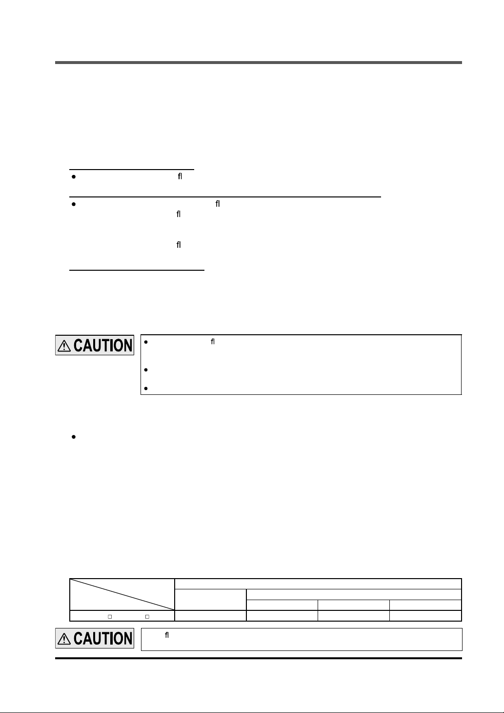
5-2 Dimensions
65
30
(Unit: mm)
25.4
23
ø6 cable 0.5m long
140
39 SUNX Limited MJE-SFCHC No.0013-09V
Page 41

Revision history
First edition September 10, 2009
Second edition November 20, 2009
40SUNX Limited MJE-SFCHC No.0013-09V
Page 42

(MEMO)
41 SUNX Limited MJE-SFCHC No.0013-09V
Page 43

1. WARRANTIES:
(1) Subject to the exclusions stated in 2 (EXCLUSIONS) herein below, SUNX warrants the Products to be free of
defects in material and workmanship for a period of one (1) year from the date of shipment under normal usage in environments commonly found in manufacturing industry.
(2) Any Products found to be defective must be shipped to SUNX with all shipping costs paid by Purchaser or of-
fered to SUNX for inspection and examination. Upon examination by SUNX, SUNX will, at its sole discretion,
repair or replace at no charge, or refund the purchase price of, any Products found to be defective.
2. EXCLUSIONS:
(1) This warranty does not apply to defects resulting from any cause:
(i) which was due to abuse, misuse, mishandling, improper installation, improper interfacing, or improper
repair by Purchaser;
(ii) which was due to unauthorized modi cation by Purchaser, in part or in whole, whether in structure,
performance or speci cation;
(iii) which was not discoverable by a person with the state-of-the-art scienti c and technical knowledge at
the time of manufacture;
(iv) which was due to an operation or use by Purchaser outside of the limits of operation or environment
speci ed by SUNX;
(v) which was due to normal wear and tear;
(vi) which was due to Force Majeure; and
(vii) which was due to any use or application expressly discouraged by SUNX in 4 (CAUTIONS FOR SAFE
USE) hereunder.
(2) This warranty extends only to the rst purchaser for application, and is not transferable to any person or entity
which purchased from such purchaser for application.
3. DISCLAIMERS
(1) SUNX's sole obligation and liability under this warranty is limited to the repair or replacement, or refund of the
purchase price, of a defective Product, at SUNX's option.
(2) THE REPAIR, REPLACEMENT, OR REFUND IS THE EXCLUSIVE REMEDY OF THE PURCHASER, AND
ALL OTHER WARRANTIES, EXPRESS OR IMPLIED, INCLUDING, WITHOUT LIMITATION, THE WARRAN-
TIES OF MERCHANTABILITY, FITNESS FOR A PARTICULAR PURPOSE, AND NON-INFRINGEMENT OF
PROPRIETARY RIGHTS, ARE HEREBY EXPRESSLY DISCLAIMED. IN NO EVENT SHALL SUNX AND
ITS AFFILIATED ENTITIES BE LIABLE FOR DAMAGES IN EXCESS OF THE PURCHASE PRICE OF THE
PRODUCTS, OR FOR ANY INDIRECT, INCIDENTAL, SPECIAL OR CONSEQUENTIAL DAMAGES OF ANY
KIND, GENERAL TERMS AND CONDITIONS 4 OR ANY DAMAGES RESULTING FROM LOSS OF USE,
BUSINESS INTERRUPTION, LOSS OF INFORMATION, LOSS OR INACCURACY OF DATA, LOSS OF
PROFITS, LOSS OF SAVINGS, THE COST OF PROCUREMENT OF SUBSTITUTED GOODS, SERVICES
OR TECHNOLOGIES, OR FOR ANY MATTER ARISING OUT OF OR IN CONNECTION WITH THE USE OR
INABILITY TO USE THE PRODUCTS.
4. CAUTIONS FOR SAFE USE
(1) The applications shown in the catalogue are only suggestions, and it is Purchaser's sole responsibility to as-
certain the tness and suitability of the Products for any particular application, as well as to abide by Purchas-
er's applicable local laws and regulations, if any.
(2) Never use the Products NOT rated or designated as “SAFETY SENSOR” in any application involving risk to
life or property. When such a use is made by Purchaser, such Purchaser shall indemnify and hold harmless
SUNX from any liability or damage whatsoever arising out of or in relation to such use.
(3) In incorporating the Products to any equipment, facilities or systems, it is highly recommended to employ fail-
safe designs, including but not limited to a redundant +++design, ame propagation prevention design, and
malfunction prevention design so as not to cause any risk of bodily injury, re accident, or social damage due
to any failure of such equipment, facilities or systems.
(4) The Products are each intended for use only in environments commonly found in manufacturing industry,
and, unless expressly allowed in the catalogue, speci cation or otherwise, shall not be used in, or incorpo-
rated into, any equipment, facilities or systems, such as those:
(a) which are used for the protection of human life or body parts;
(b) which are used outdoors or in environments subject to any likelihood of chemical contamination or
electromagnetic in uence;
(c) which are likely to be used beyond the limits of operations or environments speci ed by SUNX in the
catalogue or otherwise;
(d) which may cause risk to life or property, such as nuclear energy control equipment, transportation
equipment (whether on rail or land, or in air or at sea), and medical equipment;
(e) which are operated continuously each day for 24 hours; and
(f) which otherwise require a high level of safety performance similar to that required in those equipment,
facilities or systems as listed in (a) through (e) above.
5. EXPORT CONTROL LAWS
In some jurisdictions, the Products may be subject to local export laws and regulations. If any diversion or re-
export is to be made, Purchaser is advised to abide by such local export laws and regulations, if any, at its
own responsibility.
42SUNX Limited MJE-SFCHC No.0013-09V
Page 44

 Loading...