


sAFETY LIGHT CURTAIN
SF4C
Instruction Manual

BEFORE BEGINNING
The printed English and Japanese versions of this instruction manual are the original versions.
The English, French, German, Italian and Spanish versions published in the Internet are
copies of the original documentation and were produced by Panasonic Electric Works Europe
AG.
Liability and Copyright for the Hardware
This manual and everything described in it are copyrighted. You may not copy this manual, in
whole or part, without written consent of Panasonic Electric Works Europe AG (PEWEU).
PEWEU pursues a policy of continuous improvement of the design and performance of its
products. Therefore we reserve the right to change the manual/product without notice. In no
event will PEWEU be liable for direct, special, incidental, or consequential damage resulting
from any defect in the product or its documentation, even if advised of the possibility of such
damages.
We invite your comments on this manual. Please e-mail us at:
tech-doc@eu.pewg.panasonic.com.
Please direct support matters and technical questions to your local Panasonic representative.
LIMITED WARRANTY
If physical defects caused by distribution are found, PEWEU will replace/repair the product
free of charge. Exceptions include:
• When physical defects are due to different usage/treatment of the product other than
described in the manual.
• When physical defects are due to defective equipment other than the distributed
product.
• When physical defects are due to modifications/repairs by someone other than
PEWEU.
• When physical defects are due to natural disasters.
Important Symbols
One or more of the following symbols may be used in this documentation:
DANGER!
1.
2.
3.
!
CAUTION
Indicates that you should proceed with caution. Failure to do so may result in
injury or significant damage to instruments or their contents, e.g. data.
NOTE
Contains important additional information.
EXAMPLE
Contains an illustrative example of the previous text section.
Procedure
The warning triangle indicates especially important safety
instructions. If they are not adhered to, the results could be fatal
or critical injury.
Indicates that a step-by-step procedure follows.
REFERENCE
Indicates where you can find additional information on the subject at hand.

SF4C Safety light curtain
Table of Contents
Table of Contents
1. Introduction ............................................................................1
1.1 Target Group ............................................................................................. 2
1.2 Safety Instructions..................................................................................... 3
1.3 Applicable Standards and Regulations...................................................... 6
2. Before Using this Device .......................................................7
2.1 Confirmation of Packed Contents..............................................................8
2.2 Features..................................................................................................... 9
2.3 Part Description....................................................................................... 10
2.3.1 How the Display Works ............................................................................11
2.3.2 Operation of Large Multi-Purpose Indicator.............................................14
2.4 Protection Area........................................................................................ 15
2.4.1 Sensing Area............................................................................................ 15
2.4.2 Safety Distance ........................................................................................ 16
2.4.2.1 Calculation Example for Europe .....................................................18
2.4.2.2 Calculation Example for US ............................................................20
2.4.3 Influence of Reflective Surface ................................................................22
2.4.4 Device Placement ....................................................................................22
2.5 Mounting .................................................................................................. 25
2.5.1 Mounting with Standard Mounting Bracket .............................................. 25
2.5.2 Mounting with Multifunctional Mounting Bracket MS-SFC-3 (optional) ...26
2.5.3 Dead Zoneless Mounting .........................................................................28
2.5.4 Mounting the Intermediate Supporting Bracket MS-SFC-4 .....................31
2.5.5 Mounting the Protective Metal Case ........................................................ 32
iii

Table of Contents
SF4C Safety light curtain
2.6 Wiring .......................................................................................................34
2.6.1 Power Supply Unit....................................................................................34
2.6.2 PNP Output ..............................................................................................36
2.6.3 NPN Output ..............................................................................................38
2.6.4 Output Signal during Self-Diagnosis ........................................................39
2.6.5 Connecting Procedure and Pin Assignment ............................................40
2.6.6 Basic Wiring .............................................................................................42
2.7 Wiring Examples ......................................................................................44
2.7.1 Manual Reset When Interlock is Active....................................................44
2.7.2 Auto-Reset When Interlock is Inactive (Control Category 4) ...................45
2.7.3 Active Safety Input Function (Control Category 4)...................................47
2.7.4 Inactive External Device Monitor Function (Control Category 4).............49
2.7.5 Active Muting Function (Control Category 4) ...........................................51
2.7.6 Beam-axis Alignment ...............................................................................54
2.7.7 Operation Test..........................................................................................56
3. Functions.............................................................................. 59
3.1 Self-Diagnosis Function ...........................................................................60
3.2 Interlock Function .....................................................................................61
3.3 Test Input Function...................................................................................62
3.4 Safety Input Function ...............................................................................63
3.4.1 Serial Connection and Response Time....................................................64
3.4.2 Wiring Example for Safety Contact ..........................................................65
3.4.3 Wiring Example for Safety Sensor ...........................................................66
3.5 Large Multi-purpose Indicator Function....................................................70
3.5.1 Wiring Example of the Large Multi-Purpose Indicator..............................70
3.6 Auxiliary Output (Non-Safety Output).......................................................72
3.7 External Device Monitor Function ............................................................73
3.8 Muting Function........................................................................................75
iv
3.8.1 Specification for the Muting Sensor .........................................................76

SF4C Safety light curtain
3.8.2 Installation of the Muting Sensor.............................................................. 77
3.8.3 Installation Only for the Exit of the Object................................................79
Table of Contents
3.9 Override Function .................................................................................... 81
3.10 Functions of the Optional Handy Controller SFC-HC .............................. 84
4. Operation ..............................................................................87
4.1 Normal Operation .................................................................................... 88
4.2 Using the Test Input Function.................................................................. 90
4.3 When an Error Occurs ............................................................................. 92
4.4 Using the Muting Input Function .............................................................. 93
4.5 Using the Safety Input Function............................................................... 95
5. Maintenance..........................................................................97
5.1 Daily Inspection List................................................................................. 98
5.2 Periodic Inspection Checklist (Every Six Months) ................................. 100
5.3 Inspection after Maintenance................................................................. 101
6. Troubleshooting .................................................................103
6.1 Emitter-Related Problems...................................................................... 104
6.1.1 Indicator Section of the Emitter.............................................................. 104
6.1.2 All Indicators Are OFF............................................................................104
6.1.3 Digital Error Indicator (Red) Lights Up or Blinks .................................... 104
6.1.4 Setting Indicator Lights Up..................................................................... 106
6.1.5 Test input Indicator (Orange) Lights Up................................................. 106
6.1.6 Operation Indicator Remains Lit in Red ................................................. 106
6.2 Receiver-Related Problems................................................................... 107
6.2.1 Indicator Section of the Receiver ...........................................................107
v

Table of Contents
6.2.2 All Indicators Are OFF ............................................................................107
6.2.3 Setting Indicator "C" Lights Up...............................................................107
6.2.4 Fault Indicator (Yellow) Lights up or Blinks............................................108
SF4C Safety light curtain
7. Specifications and Dimensions ........................................ 111
7.1 Specifications by Model Numbers ..........................................................112
7.1.1 Model Numbers SF4C-Hxx<V2> with 20mm Beam Pitch......................112
7.1.2 Model Numbers SF4C-Hxx with Pigtailed Type.....................................113
7.2 Common Specifications..........................................................................114
7.3 Options ...................................................................................................117
7.3.1 Cables ....................................................................................................117
7.3.1.1 Extension Cable with Connector on One End...............................117
7.3.1.2 Extension Cable with Connectors on Both Ends ..........................117
7.3.1.3 Y-Type Connector .........................................................................118
7.3.2 Brackets..................................................................................................118
7.3.2.1 Standard Mounting Bracket MS-SFC-1.........................................118
7.3.2.2 NA2_N Compatible Mounting Bracket ..........................................118
7.3.2.3 Multifunctional Mounting Bracket MS-SFC-3 ................................ 119
7.3.2.4 Mounting Bracket MS-SFC-4 ........................................................119
7.3.3 Protective Metal Case ............................................................................120
7.3.4 Handy Controller ....................................................................................120
7.3.5 Test Rod.................................................................................................121
8. Dimensions......................................................................... 123
8.1 Mounting Dimensions.............................................................................124
8.1.1 Centered Mounting with Standard Mounting Brackets...........................124
8.1.2 Standard Mounting Bracket without Dead Space ..................................125
8.1.3 Multifunctional Mounting Bracket ...........................................................126
8.1.4 Multifunctional Mounting Bracket without dead zone.............................127
vi
8.1.5 Mounting of the Protective Metal Case ..................................................128

SF4C Safety light curtain
Table of Contents
8.2 Mounting Brackets ................................................................................. 129
8.2.1 Standard Mounting Bracket MS-SFC-1 .................................................129
8.2.2 Mounting Bracket MS-SFC-2 ................................................................. 129
8.2.3 Multifunctional Mounting Bracket MS-SFC-3......................................... 130
8.2.4 Multifunctional Mounting Bracket MS-SFC-3 (without Dead Zone) ...... 130
8.2.5 Multifunctional Intermediate Supporting Bracket MS-SFC-4 ................. 131
8.2.6 Protective Metal Case ............................................................................ 131
9. Glossary of Terms..............................................................133
10. Index ...................................................................................135
vii

Chapter 1
Introduction

Introduction
SF4C Safety light curtain
1.1 Target Group
Thank you for purchasing the Safety Light Curtain from the SF4C series. Please read this
instruction manual carefully and thoroughly for the correct and optimum use of this product.
Kindly keep this manual in a convenient place for quick reference.
The SF4C is a light curtain for protecting a person from dangerous parts of a machine which can
cause injury or accident.
This manual has been written for the following personnel who:
• have undergone suitable training and have knowledge of light curtains as well as safety
systems and standards.
• who are responsible for the introduction of this device
• who design systems using the SF4C
• who install and connect the SF4C
• who manage and operate a plant using the SF4C
Machine designer, installer, employer and operator
The machine designer, installer, employer and operator are solely responsible for ensuring that
all applicable legal requirements relating to the installation and the use in any application are
satisfied and all instructions for installation and maintenance contained in the instruction manual
are followed.
Whether this device functions as intended and systems including the SF4C comply with safety
regulations depend on the appropriateness of the application, installation, maintenance and
operation. The machine designer, installer, employer and operator are solely responsible for
these items.
Engineer
The engineer must be a person who is appropriately trained, has widespread knowledge and
experience, and can solve various problems which may arise in his field of work, e.g. as a
machine designer or a person in charge of installation or operation, etc.
Operator
The operator should read this instruction manual thoroughly, understand its contents, and
perform operations following the procedures described in this manual for the correct operation
of this device.
In case this device does not perform properly, the operator should report this to the person in
charge and stop machine operation immediately. The machine must not be used until correct
performance of this device has been confirmed.
2

SF4C Safety light curtain
1.2 Safety Instructions
DANGER!
1.2 Safety Instructions
!
• Use the SF4C as per its specifications. Do not modify the safety light curtain
since its functions and capabilities may not be maintained and it may
malfunction.
• The SF4C has been developed/produced for industrial use only.
• Do not use the SF4C under conditions or in environments not described in
this manual. Please consult us if there is no other choice but to use this
device in such an environment.
• Do not use the safety light curtain in fields such as nuclear power control,
railroad, aircraft, automobiles, combustion facilities, medical systems,
aerospace development, e.g. in applications where failure could result in
large-scale damage to society or people.
• When the safety light curtain is to be used for enforcing protection of a
person from any danger occurring around an operating machine, the user
must satisfy the regulations established by national or regional security
committees.
• No matter what kind of equipment you use the device with, follow the safety
regulations in regard to appropriate usage, mounting (installation), operation
and maintenance.
Please adhere to the following safety instructions when
you install and operate the SF4C. Failure to do so can
result in fatal or critical injury during unprotected use of
hazardous machinery.
• Use the safety light curtain by installing suitable protective equipment as a
countermeasure for failure, damage, or malfunction of this device.
• Before using this light curtain, check whether it performs properly and has
the functions and capabilities as stated in the design specifications.
• Dispose of the safety light curtain as industrial waste.
Environment
• Do not use a mobile phone or a radio phone near the SF4C.
• If the safety light curtain is installed in a place where there are reflective
surfaces, make sure to install it so that reflected light from the reflective
surfaces does not affect the receiver. Alternatively, take countermeasures
such as painting, masking, roughening, or changing the material of the
reflective surfaces, etc. Failure to do so may cause the SF4C not to detect
properly, which may result in death or serious injury.
• Do not install the safety light curtain in the following environments:
- Areas exposed to intense interference light such as direct sunlight
3

Introduction
Installation
• Always keep the correctly calculated safety distance between the safety light
• Install an extra protective structure around the machine so that the operator
• Install the safety light curtain in a manner that some part of the operator's
• Do not install the safety light curtain at a location where it can be affected by
SF4C Safety light curtain
- Areas with high humidity where condensation is likely to occur
- Areas exposed to corrosive or explosive gases
- Areas exposed to vibration or shock at levels higher than those specified
- Areas exposed to contact with water
- Areas exposed to excessive steam or dust
- Areas where the beam-receiving part of this device is directly exposed to
light from a high-frequency fluorescent lamp (inverter type) or
rapid-starter fluorescent lamp.
curtain and the dangerous parts of the machine.
must pass through the sensing area of the safety light curtain to reach the
dangerous parts of the machine.
body always remains in the sensing area until the operator has finished
working with the dangerous parts of the machine.
wall reflection.
• When installing multiple sets of the SF4C, connect the sets and, if necessary,
install some barriers so that mutual interference does not occur.
• Do not use any reflection type or recursive reflection type arrangement.
Equipment in which this device is installed
• When the safety light curtain is used in the PSDI (see page
appropriate control circuit must be configured between this device and the
machinery. For details, be sure to refer to the standards or regulations
applicable in each region or country.
• In Japan, do not use the SF4C as safety equipment for a press machine.
• Do not install the SF4C with a machine whose operation cannot be stopped
immediately in the middle of an operation cycle by an emergency stop.
• The SF4C provides safety 2 seconds after the power has been switched ON.
Make sure that the control system takes the time delay into consideration.
Wiring
• Switch off the power before wiring the safety light curtain.
• All electrical wiring should conform to the regional electrical regulations and
laws. The wiring should be done by skilled personnel with the required
electrical knowledge.
• Do not run the sensor cable together with high-voltage lines or power lines
or put them together in the same raceway.
134) mode, an
4

SF4C Safety light curtain
• In case you need to extend the cable of the emitter or the receiver, each can
be extended up to 40.5m by using the exclusive cable. Furthermore, if the
cable is extended and the muting lamp is used, the allowed total extendable
length is reduced (see "
40).
• Do not control the device at only one control output (OSSD 1, OSSD 2) (see
page
133).
• To ensure that the output is not turned ON due to an earth fault of the control
output (OSSD 1, OSSD 2), ground the device on the 0V side (for PNP output)
or +24V side (for NPN output).
Maintenance
• When you need to replace parts, always use only genuine replacement parts
from the supplier. If you use substitute parts from another manufacturer, the
safety light curtain may fail to detect properly, which may result in death or
serious body injury.
• The device must be inspected periodically by an engineer with the required
knowledge.
• When you have adjusted or maintained the SF4C, test the device following
the procedure specified in the maintenance chapter (see page
switch the system back on.
1.2 Safety Instructions
Connecting Procedure and Pin Assignment" on page
97) before you
Others
• Clean this device with a clean cloth. Do not use thinner-based cleaners.
• Never modify this device. If you modify the SF4C, the safety light curtain may
fail to detect properly, which may result in death or serious injury.
• Do not use the safety light curtain to detect objects flying over the sensing
area.
• Do not use this device to detect transparent objects, translucent objects or
objects smaller than the specified minimum sensing size.
5
Introduction
SF4C Safety light curtain
1.3 Applicable Standards and Regulations
This device complies with the following standards and regulations.
• EU Machinery Directive 98/37/EC, EU Machinery Directive 2006/42/EC, EMC Directive
2004/108/EC
• EN 61496-1 (Type 4), EN 55011
• IEC 61496-1/2 (Type 4), ISO 13849-1:2006 (Category 4, PLe), IEC 61508-1 to 7 (SIL3)
• JIS B 9704-1/2 (Type 4), JIS B 9705-1 (ISO 13849-1) (Category 4), JIS C 0508-1 to 7
(SIL3)
• UL 61496-1/2 (Type 4), UL 508, UL 1998 (Class 2), CSA 61496-1 / 2 (Type 4), CSA
C22.2 No.14
• OSHA 1910.212, OSHA 19 10.217(C), ANSI B11.1 to B11.19, ANSI/RIA 15.06
NOTE
• Conformity to JIS, OSHA and ANSI for this device has been evaluated by us.
•
directive. The CE-mark indicates that this product conforms to the EMC
directive.
•
•
Canadian and U.S. requirements.
• If you want to use this device in a location other than already described (see
page
regulations applicable in your region or country.
: This device conforms to the EMC directive and the Machinery
: This device is certified by TÜV Süd.
: The C-CL US Listing Mark indicates compliance with both
3), confirm first that the intended use complies with the standards or
6

Chapter 2
Before Using this Device

Before Using this Device
2.1 Confirmation of Packed Contents
Check mark Number Package content
SF4C Safety light curtain
□ 1 piece
□ 1 piece
□ 1 piece
Sensor with 1 emitter and 1 receiver
Test rod
Instruction manual (this manual)
8

SF4C Safety light curtain
2.2 Features
This device is the light curtain with the following features.
No special controller is required.
• Cable type or pigtailed type is available.
• The control output (OSSD 1/2) is a PNP / NPN output switching type.
• Large multi-purpose indicators (red, green) which are bright and easy-to-see are
incorporated.
2.2 Features
• Each function can be set by using the handy controller SFC-HC (optional), see page
• For details of options, see "
Options" on page 117.
84.
9
Before Using this Device
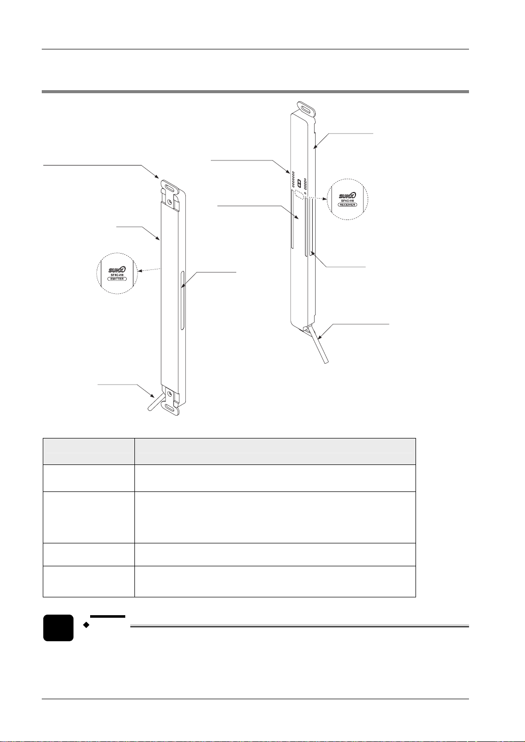
2.3 Part Description
Standard mounting
bracket MS-SFC-1
(Accessory)
Emitter
Model
information
Display section
Beam-channel
Large
multi-purpose
indicator
SF4C Safety light curtain
Receiver
Model
information
Large multi
-purpose
indicator
Gray cable
(with black line)
Gray cable
Parts of the safety light curtain
Part Description
Emitter
Receiver
Beam channel
Standard mounting
bracket MS-SFC-1
(accessory)
NOTE
Emits light to the receiver facing it. Furthermore, the status of the emitter is
indicated on its display section.
Receives light from the emitter facing it. Simultaneously the control output
(OSSD 1, OSSD 2) turns ON when the all beam channels receive light from
the emitter, and the control output (OSSD 1, OSSD 2) turns OFF when one
or more beam channels are blocked. (Except when using the muting
function, see note).
The light-emitting elements of the emitter and the light-receiving elements of
the receiver are placed at the intervals of 20mm.
Use these brackets to mount both the emitter and receiver.
• In case of using the muting function, muting sensors and a muting lamp are
required. Please purchase these items separately.
10
SF4C Safety light curtain
• The blanking function is set with the handy controller SFC-HC (optional), see
84. Please purchase the handy controller separately.
page
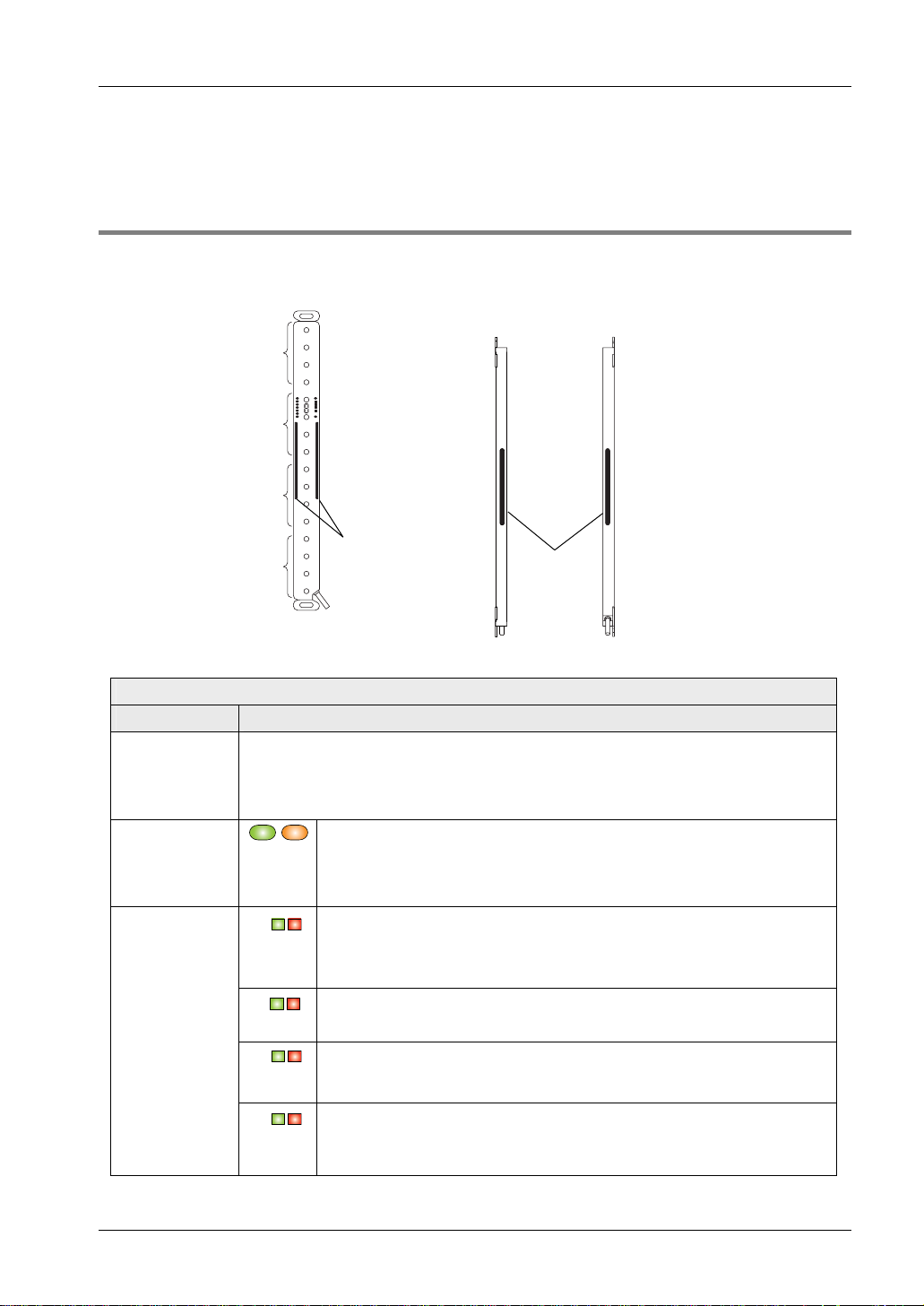
2.3.1 How the Display Works
Front view Side view (left and right)
Position of beam-axis alignment
indicators
A
2.3 Part Description
Location of
beam-axis
alignment
indicators
B
C
Large
D
multipurpose
indicator
The description given in [ ] is marked on the sensor.
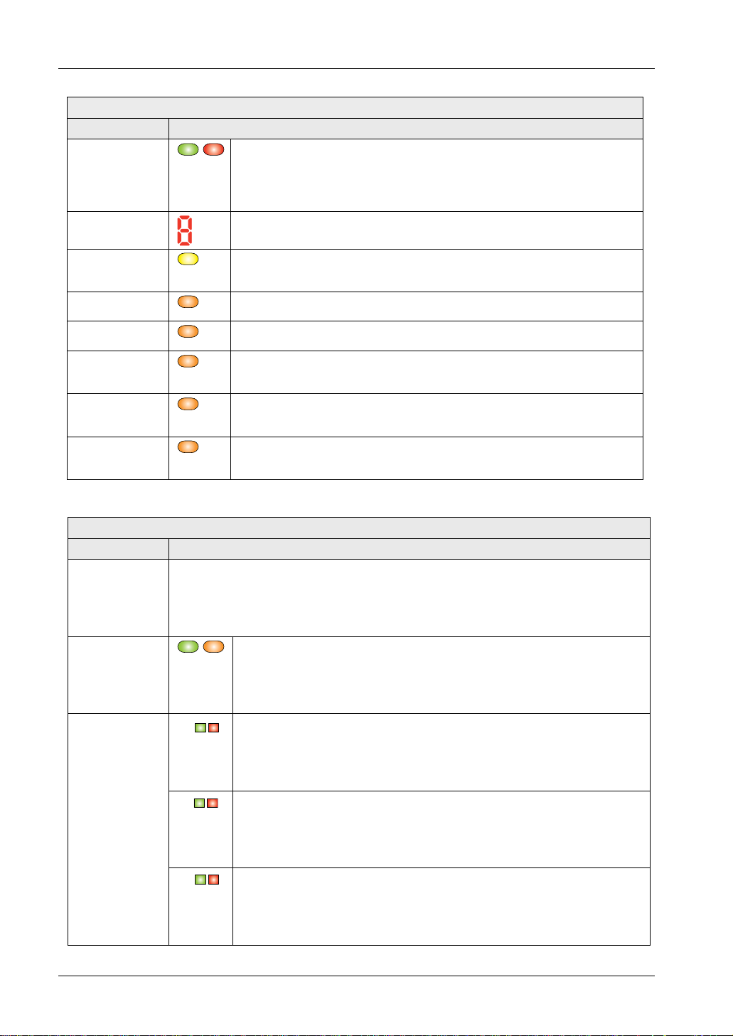
Emitter
Function Description
Large
multi-purpose
indicator
(Note 1)
Incident light
intensity
indicator
(green/orange)
[STB]
Beam-axis
alignment
indicator
(green/red)
[RECEPTION]
Lights up in red when the large multi-purpose indicator input is ON.
Lights up in green when the large multi-purpose indicator input is ON.
There is no color display, when the input is OFF. With the optional handy controller you have
further setting possibilities, see "
Lights up in green when stable light is received.
Lights up in orange when unstable light is received.
Turns OFF when light is blocked. (Note 2)
A
B
C
When the control output (OSSD 1/2) is ON: lights up green.
When the top block receives light: lights up red.
When the top end receives light: blinks red.
When the control output (OSSD 1/2) is ON: lights up green.
When the upper middle block receives light: lights up red.
When the control output (OSSD 1/2) is ON: lights up green.
When the lower middle block receives light: lights up red.
Operation of Large Multi-Purpose Indicator" on page 14.
Large
multipurpose
indicator
D
When the control output (OSSD 1/2) is ON: lights up green.
When the bottom block receives light: lights up red.
When the bottom end receives light: blinks red.
11
Before Using this Device
Emitter
Function Description
Operation
indicator
[OSSD]
(green/red),
(Note 3)
Digital error
indicator (red)
Fault indicator
[FAULT]
(yellow)
PNP indicator
[PNP] (orange)
NPN indicator
[NPN] (orange)
Test input
indicator [TEST]
(orange)
Safety input 1
indicator [S1]
(orange)
Safety input 2
indicator [S2]
(orange)
Lights up when the sensor operation is as follows (OSSD 1/2):
When the control output (OSSD 1/2) is ON: lights up green.
When the control output (OSSD 1/2) is OFF: lights up red.
When the safety light curtain is in the lockout state, the error contents are
displayed here.
When a fault occurs in the sensor: lights up or blinks.
When the PNP output is set: lights up
When the NPN output is set: lights up
Lights up when test input is active.
Turns OFF when test input is inactive.
Lights up when safety input 1 is active.
Turns OFF when safety input 1 is inactive.
Lights up when the safety input 2 is active.
Turns OFF when the safety input 2 is inactive.
The description given in [ ] is marked on the sensor.
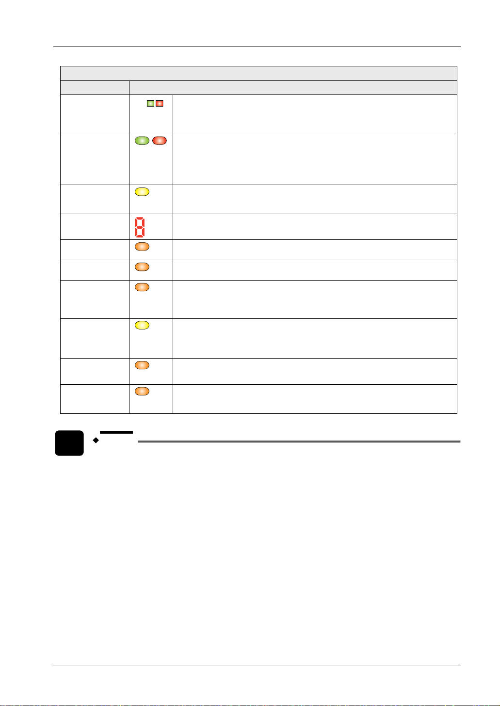
Receiver
Function Description
Large
multi-purpose
indicator
(Note 1)
Lights up in red when the large multi-purpose indicator input is active.
Lights up in green when the large multi-purpose indicator input is active.
Turns OFF when the input is inactive.
SF4C Safety light curtain
Incident light
intensity
indicator (green
/orange) [STB]
Beam-axis
alignment
indicator
(green/red)
[RECEPTION]
12
Lights up in green when stable light is received.
Lights up in orange when unstable light is received.
Turns OFF when light is blocked. (Note 2)
A
B
C
When the control output (OSSD 1/2) is ON: lights up green.
When the top block receives light: lights up red.
When the top end receives light: blinks red.
When the control output (OSSD 1/2) is ON: lights up green.
When the upper middle block receives light: lights up red.
When the control output (OSSD 1/2) is ON: lights up green.
When the lower middle block receives light: lights up red.
SF4C Safety light curtain
Receiver
Function Description
OSSD indicator
[OSSD]
(green/red),
(Note 3)
D
When the control output (OSSD 1/2) is ON: lights up green.
When the bottom block receives light: lights up red.
When the bottom end receives light: blinks red.
Lights up when the sensor operation is as follows (OSSD 1/2):
When the control output (OSSD 1/2) is ON: lights up green.
When the control output (OSSD 1/2) is OFF: lights up red.
2.3 Part Description
Fault indicator
[FAULT]
(yellow)
Digital error
indicator (red)
PNP indicator
[PNP] (orange)
NPN indicator
[NPN] (orange)
Function setting
indicator
(orange)
[FUNCTION]
Interlock
indicator
[INTERLOCK]
(yellow)
Muting input 1
(orange) [MU1]
Muting input 2
indicator
(orange) [MU2]
NOTE
When a fault occurs in the sensor: lights up or blinks.
When the safety light curtain is in the lockout state, the error contents are
displayed here.
When the PNP output is set: lights up
When the NPN output is set: lights up
Blinks when the handy controller is connected.
Lights up when blanking function is active. (Note 4)
Lights up when interlock is active.
Turns OFF, when interlock is inactive.
Lights up when the muting input 1 is active.
Turns off when the muting input 1 is inactive.
Lights up when the muting input 2 is active.
Turns off when the muting input 2 is inactive.
The operation of the large multi-purpose indicator (lights up, blinks or turns OFF) can be set by
using the handy controller SFC-HC (optional), see page
84.
The status "when light is blocked" refers to the status when there is an obstacle in the sensing
area.
Since the color of the operation indicator changes according to whether the control output
(OSSD 1/2) is ON or OFF, the operation indicator on the sensor is marked "OSSD".
The blanking function is set by using the handy controller SFC-HC (optional), see page
84.
The threshold where the control output (OSSD 1/2) changes from OFF to ON is applied as
"100% incident light intensity".
13
Before Using this Device
SF4C Safety light curtain
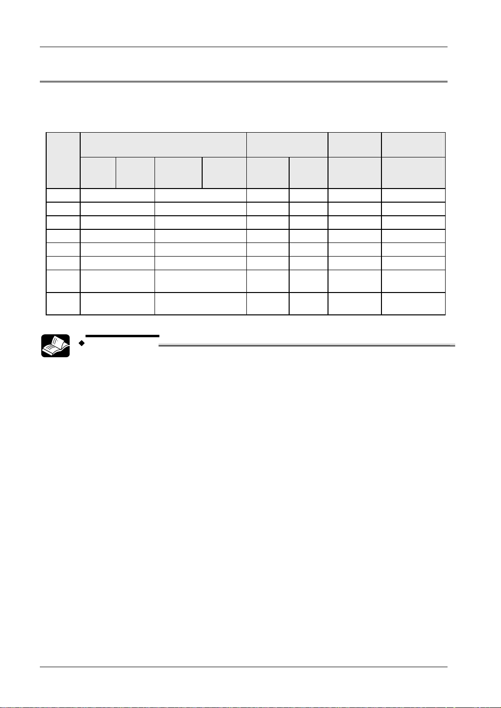
2.3.2 Operation of Large Multi-Purpose Indicator
You have different settings available for the large multi-purpose indicator with the handy
controller SFC-HC (optional), see page
mode numbers. Factory setting is mode 0.
Mode
0
1
2
3
4
5
6
7
Large multi-purpose indicator input
1/2
PNP
output:
ON
Lights up red Lights up green –- –- –- –Blinks red Blinks green –- –- –- –Lights up red Blinks green –- –- –- –Blinks red Lights up green –- –- –- –Lights up red Blinks red –- –- –- –Blinks green Lights up green –- –- –- ––- –- Lights up
Lights up red Blinks red –- –- Lights up
NPN
output:
OFF
PNP
output:
OFF
84. One mode can be selected from the following eight
PNP
output:
ON
OSSD 1/2
Muting
function
ON OFF Active Inactive
green
Lights
up red
Blinks green –-
green
Override
function
Blinks green
REFERENCE
Further information regarding the functionality of the handy controller you find
in the operation manual for the handy controller or see page
84.
14
SF4C Safety light curtain
2.4 Protection Area
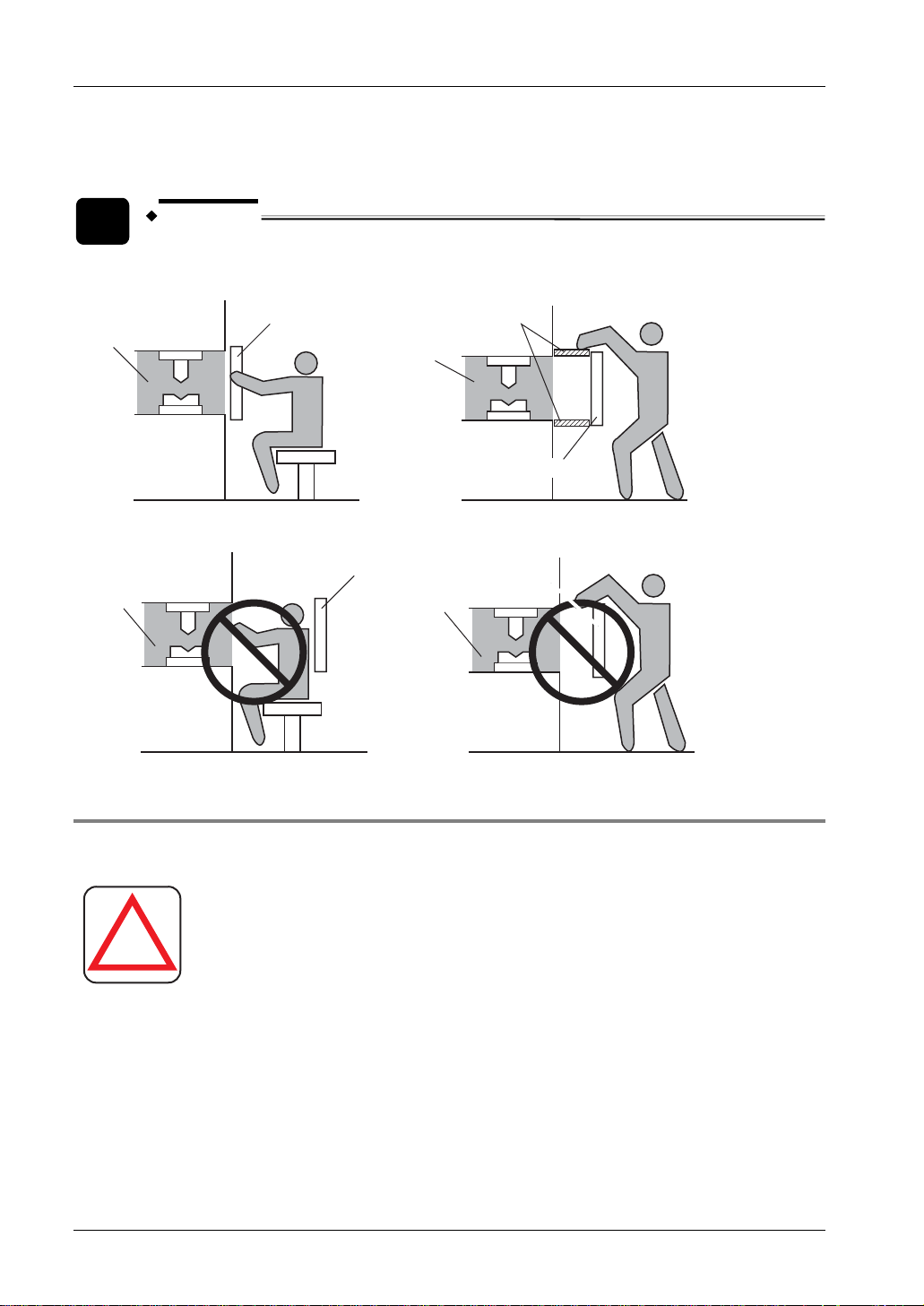
2.4.1 Sensing Area
DANGER!
2.4 Protection Area
!
operator must pass through the sensing area of this device to reach
the dangerous parts of the machine.
Furthermore, ensure that some part of the operator's body always
remains in the sensing area while the operator works on the
dangerous parts of the machine.
Do not use any arrangement using reflection or recursive reflection.
Follow the below descriptions carefully. Failure to do so may result
Install a protective structure around the machine so that the
in serious injury or death.
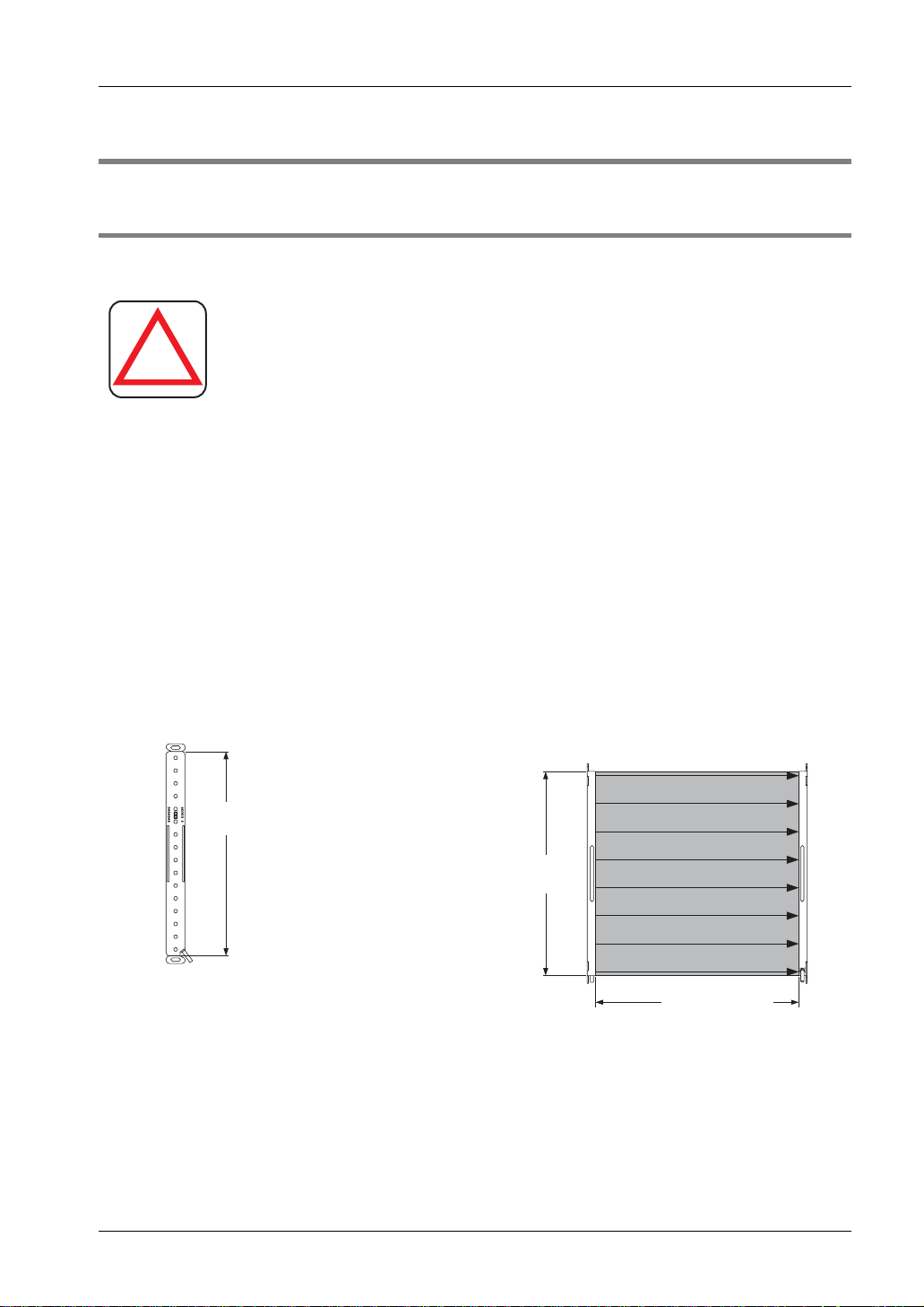
The sensing area is the zone formed by the sensing height of the sensor and the sensing range
between the emitter and the receiver. The sensing height is determined by the number of beam
channels.
The sensing range depends on the device type: 0.1 to 3m. Also remember that if the sensing
range is less than 0.1m, malfunction may occur due to the optical structure.
Sensing height, sensing range, and sensing area
To p
Sensing height
The sensing height is the
area between the line
indicated in the top part
and line indicated in the
bottom part.
Emitter Receiver
Bottom
Sensing
height
Sensing area
Sensing range
When connecting the sensor, use the correct combination of emitter and receiver (same beam
pitch and number of beam channels) and match their top-bottom orientation. Combining
different types of emitters and receivers may produce a non-sensing area.
15
Before Using this Device
SF4C Safety light curtain
Do not arrange several receivers facing one emitter, or vice versa, as this could produce a
non-sensing area or cause mutual interference.
EXAMPLE
Correct installation
Dangerous
part
Sensing
area
Incorrect installation
Dangerous
part
2.4.2 Safety Distance
Dangerous
Sensing area
Protective structure
part
Sensing area
Dangerous
Sensing area
part
DANGER!
!
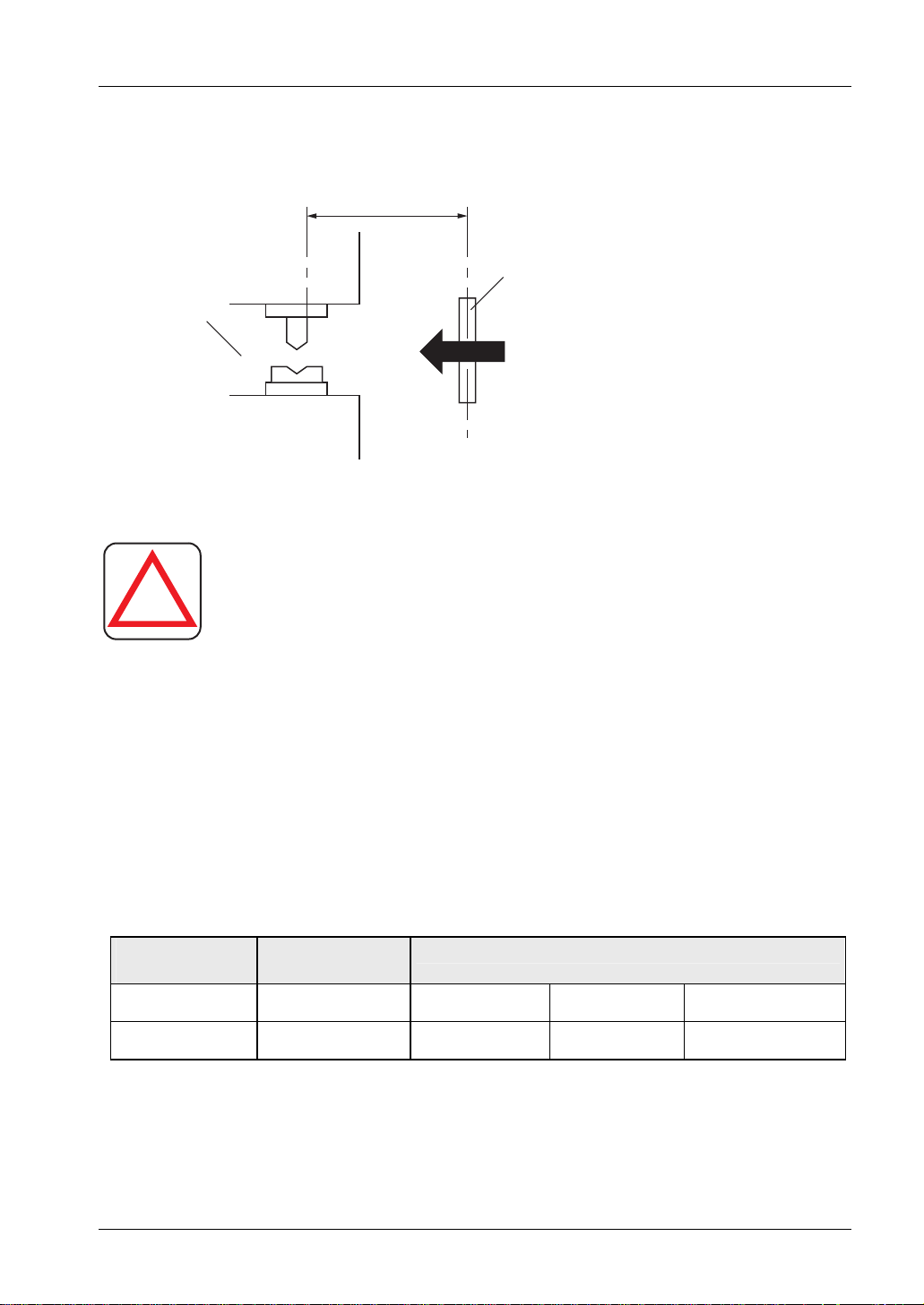
The safety distance is the minimum distance that must be maintained between the light curtain
and the dangerous parts of the machine so that the machine can be stopped before a human
body or an object can reach the dangerous parts.
The safety distance is calculated based on the equation described on the next page when a
person moves (normal intrusion) at a straight angle into the sensing area of the sensor.
16
Calculate the safety distance correctly and always maintain a
distance equal to or greater than the safety distance between the
sensing area of this device and the dangerous parts of the machine.
If the safety distance is miscalculated or not sufficient, the machine
will not stop quickly enough when a human body or an object
reaches the dangerous parts, which may result in serious injury or
death.
SF4C Safety light curtain
2.4 Protection Area
In case the intrusion direction is not perpendicular to the sensing area, be sure to refer to the
relevant standard for details of the calculation (regional standard, specification of the machine
etc.)
Safety distance S
Sensing area
Dangerous part
Intrusion direction
Safety distance
DANGER!
!
region where this device is to be used and then install this device.
Furthermore, the equation described on the next pages is to be
used only when the intrusion direction is perpendicular to the
sensing area, i.e. at a straight angle. If the intrusion direction is not
perpendicular to the sensing area, refer to the relevant standard
(regional standard, specification of the machine, etc.) for details of
the calculation.
The max. response time of the machine is from the point when the
machine receives the halt signal from this device to the point when
the dangerous part of the machine stops. The max. response time of
the machine should be timed with the actual machine.
The minimum size of the objects to be detected by the safety light curtain varies depending on
Before designing the system, refer to the relevant standards of the
whether the floating blanking function is used or not, see page
84. The equation differs
depending on the case whether the minimum object to be sensed is larger than ∅40mm or not.
Calculate the safety distance with the correct minimum size and the appropriate equation.
Number of beam
channels
Minimum object to
be sensed
Floating blanking
not active
∅25mm ∅45mm ∅65mm ∅85mm
Floating blanking active at (Note)
1 beam channel 2 beam channels 3 beam channels
17

Before Using this Device
NOTE
SF4C Safety light curtain
For details of the floating blanking function, see page 84.
2.4.2.1 Calculation Example for Europe
The equation for the safety distance S is calculated in accordance with EN 999 and ISO 13855.
Formula in case that the minimum sensing object is Ø40mm or less:
S: Safety distance (mm)
K: Intrusion velocity of operator's body or object (mm/s). The equation assumes an
S = K x T + C
Minimum distance required between the sensing area surface and the dangerous
parts of the machine.
intrusion direction perpendicular to the sensing area.
T:
C:
1.
2.
Response time of total equipment (s). T = T
: Maximum halt time of device (s). For determining Tm, refer to the
T
m
m
+ T
SF4C
machine documentation or take a measurement using a special device
called a 'brake monitor'.
: Response time of this device (s)
T
SF4C
Additional distance calculated from the minimum size of the object to be detected by
the sensor (mm). C has to be 0 or more. C = 8 x (d - 14)
d: Minimum object diameter (mm)
3.
Procedure
1. Calculate the safety distance S with a velocity K = 2,000mm/s
There are 3 possibilities (1-3):
1. S < 100mm Use 100mm as the safety distance.
2.100 ≤ S ≤ 500mm
3. S > 500mm Continue with the next step in the procedure
Use the calculated result as the safety
distance.
2. Recalculate S with K' = 1,600mm/s
There are 2 possibilities (4-5):
18
4. S > 500mm Use the calculated result as the safety distance.
5. S ≤ 500mm
Use 500mm as the safety distance.

SF4C Safety light curtain
When this device is used in the 'PSDI Mode', an appropriate safety distance S must be
calculated. For details, be sure to refer to the standards or regulations applicable in each region
or country.
EXAMPLE
Calculate the safety distance with the following values:
K: 2,000 mm/s
: 0.1s
T
m
: 0,7ms
T
SF4C
d: 25mm
With these values, the calculation is as follows:
S = K x T + C
2.4 Protection Area
= 2,000 x (0.1 + 0.007) + 8 x (25 - 14)
= 302
As 302 matches possibility 2 listed above, 302mm is the safety distance.
EXAMPLE
Calculate the safety distance with the following values:
K: 2,000mm/s
: 0.4s
T
m
: 7ms
T
SF4C
d: 25mm
With these values, the calculation is as follows:
S = K x T + C
= K x (T
= K x (T
= 2,000 x (0.4 + 0.007) + 8 x (25 -
m
+ T
m
+ T
) + 8 x (d - 14)
SF4C
) + 8 x (d - 14)
SF4C
14)
As 902 matches possibility 3 listed above, recalculate the safety distance with K' =
1,600mm/s.
S = K' x T + C
= 902
= K x (T
m
+ T
) + 8 x (d - 14)
SF4C
19

Before Using this Device
SF4C Safety light curtain
= 1,600 x (0.4 + 0.007) + 8 x (25 - 14)
= 739.2
As 739.2 is > 500mm, use this recalculated result as the safety distance.
Formula in case that the minimum sensing object is Ø40mm or more:
S = K x T + C
S: Safety distance (mm)
Minimum distance required between the sensing area surface and the dangerous
parts of the machine.
K: Intrusion velocity of operator's body or object (mm/s). The equation assumes an
intrusion direction perpendicular to the sensing area.
T:
Response time of total equipment (s). T = T
:
T
m
Maximum halt time of device (s). For determining T
+ T
m
SF4C
, refer to the
m
machine documentation or take a measurement using a special device
called a 'brake monitor'.
: Response time of this device (s)
T
SF4C
C: Additional distance calculated from the minimum size of the object to be detected by
the sensor (mm). C = 850 mm (Constant)
2.4.2.2 Calculation Example for US
he equation safety distance S is calculated in accordance with ANSI/RIA B15.06 with the
formula:
S = K x (T
S:
K:
Tbm
+ Tc + T
s
+ Tbm) + Dpf
SF4C
Safety distance (mm)
Minimum distance required between the sensing area surface and the dangerous
parts of the machine.
Intrusion velocity of operator's body or object. The recommended value in OSHA is
63inch/s ≈ 1,600mm/s.
ANSI/RIA B15.06 does not define the intrusion velocity 'K'. When determining K,
consider possible factors including the physical ability of operators.
Additional halting time tolerance for the brake monitor (s)
= Ta - (Ts + Tc)
T
bm
: Setting time of brake monitor (s)
T
a
When the machine is not equipped with a brake monitor, it is
recommended that 20% or more of (T
+ Tc) is taken as additional halt
s
time.
Ts: Halt time calculated from the operation time of the control element (air
20

SF4C Safety light curtain
2.4 Protection Area
T
SF4C
Dpf
valve, etc.) (s)
T
: Maximum response time of the control circuit required for the brake (s)
c
Response time of this device (s)
Additional distance calculated from the minimum size of the object to be detected by
the safety light curtain (mm) with the formula:
D
= 61.2mm
pf
NOTE
Since the calculation above is performed by taking 1 inch = 25.4mm, there is a
slight difference between the representation in mm and that in inches. Refer to
the relevant standard for details.
EXAMPLE
Calculate the safety distance with the following values:
7s
T
SF4C
d: 0.985ich ≈ 20mm
With these values, the calculation is as follows:
S = K x (T
= 63 x (T
= 63 x (T
= 63 x T
= 63 x T
≈ 63 x T
+ Tc + T
s
+ 0.014) + 3.4 x (d - 0.276)inch
a
+ 0.014) + 3.4 x (0.985 - 0.276)
a
63 x 0.007 + 3.4 x 0.709
a
+ 0,441 + 2.4106
a
2.85inch
a
+ Tbm) + Dpf
SF4C
In case this device is installed in a system with a maximum halt time 0.1 (s)
S = 63 x T
= 63 x 0.1 + 2.85
= 9.15inch ≈ 232.41mm
+ 2.85
a
Hence, as per the calculations Ds is 9.15inch ≈ 232.41mm.
21
Before Using this Device
NOTE
Since the calculation above is performed by taking 1inch = 25.4mm, there is a
slight difference between the representation in mm and that in inches. Refer to
the relevant standard for details.
2.4.3 Influence of Reflective Surface
DANGER!
SF4C Safety light curtain
!
surfaces, make sure to install this device so that reflected light
from the reflective surfaces does not affect the receiver.
Alternatively, take countermeasures such as painting, masking,
roughening, or changing the material of the reflective surfaces,
etc. Failure to do so may cause the sensor not to detect properly,
If the device is installed in a place where there are reflective
which may result in death or serious injury.
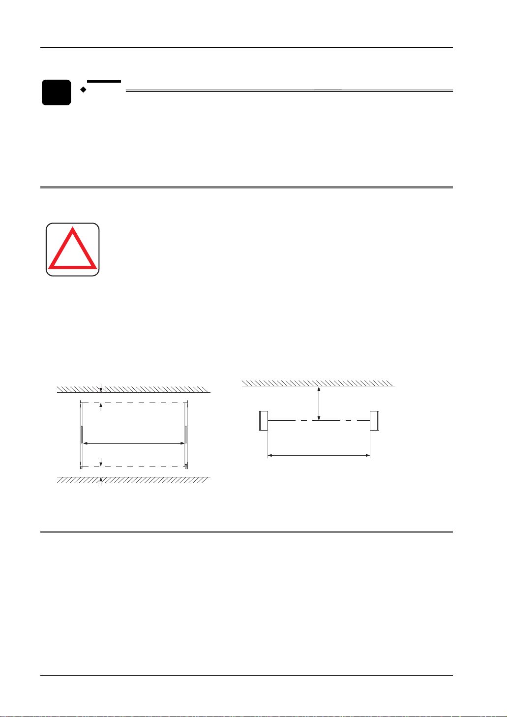
Install this device at a distance of at least 0,16m away from reflective surfaces such as metal
walls, floors, ceilings, workpieces, covers, panels or glass surfaces.
Side view Top view
Reflective surface
0.16m
Sensing range
0.1 - 3m
Receiver
Emitter
Reflective ceiling
0,16m
Sensing range
0,1 - 3m
0,16m
Reflective floor
Receiver
Emitter
2.4.4 Device Placement
If there is a problem with the wiring or when you need to evaluate the system before you add
further equipment, place two or more sets of emitters and receivers facing each other without
series or parallel connection between them. Perform an operation test (see page
22
56).

SF4C Safety light curtain
DANGER!
2.4 Protection Area
!
understand them thoroughly before installing the sensors.
Improper sensor placement could cause the sensor to
malfunction, which may result in serious injury or death.
If this device is used in multiple sets, arrange them so that
mutual interference is avoided. If mutual interference occurs,
it can result in serious injury or death.
Refer to the examples of sensor placement as follows and
EXAMPLE
1) Install the emitters or the receivers back to
back.
Receiver ReceiverEmitterEmitter
2) Arrange the emitters and the receivers
vertically on opposite sides.
Emitter
Receiver
Receiver
Emitter
3) Arrange the emitters and the receivers
horizontally on opposite sides.
Receiver
Emitter
Emitter
Receiver
4) Install a barrier
Receiver Emitter Emitter
Receiver
Barrier
23

Before Using this Device
NOTE
The figures above are just examples of sensor placement. If there are any
questions or problems, please contact our office.
SF4C Safety light curtain
24

SF4C Safety light curtain
2.5 Mounting
2.5 Mounting
The standard mounting bracket MS-SFC-1 is included with the device. Other mounting brackets
appropriate for your installation environment, has to be purchased separately. Please, also
purchase the hexagon socket head bolts separately. They are not part of the product.
• Standard mounting bracket (MS-SFC-1)
• NA2-N compatible mounting bracket (MS-SFC-2)
• Multifunctional Mounting Bracket MS-SFC-3 (see page
119)
2.5.1 Mounting with Standard Mounting Bracket
Before you start mounting the device, read the following important notes carefully.
Unless otherwise specified, the following mounting procedure is common for both emitters and
receivers. The direction of the standard mounting bracket MS-SFC-1 (accessory) which is
attached to this device can be changed depending on the mounting position of the device.
NOTE
• Do not bend the cable of this device. Applying improper loads to the cable
could cause the wire to break.
• The minimum bending radius of the cable is 6mm. Mount the sensor
accordingly.
• Mount the emitter and the receiver at the same level and parallel to each
other. The effective aperture angle of this device is ±2.5°or less for a sensing
distance exceeding 3m.
• Unless otherwise specified, the mounting procedure is common for both
emitters and receivers. To prepare the mounting holes, refer to the
dimension diagrams.
25

Before Using this Device
1.
2.
3.
Procedure
1. Loosen the M3 countersunk head screw (with anti-loosening agent, length
4mm) which is attached to the back of the device
2. Rotate the bracket to adjust the installation direction of emitter and receiver
3. Tighten the M3 countersunk head screw
The tightening torque should be 0,3N•m or less.
M3 countersunk head screw (with
anti-loosening agent, length 4mm)
Standard mounting bracket
MS-SFC-1 (Accessory)
SF4C Safety light curtain
Mountable in three directions
SF4C
4. Install the standard mounting brackets on the mounting surface with two
hexagon-socket head bolts (M5)
2.5.2 Mounting with Multifunctional Mounting Bracket MS-SFC-3 (optional)
The following procedure shows how to mount the safety light curtain with the multifunctional
mounting bracket MS-SFC-3.
26

SF4C Safety light curtain
2.5 Mounting
1.
2.
3.
Procedure
1. Remove the M3 countersunk head screw with anti-loosening agent (length
4mm) which is attached to the back of the device
M3 countersunk head screw with
anti-loosening agent (length 4mm)
SF4C
2. Then remove the standard mounting bracket MS-SFC-1
3. Mount the multifunctional mounting bracket using the M3 countersunk head
screw with anti-loosening agent (length 4mm) (accessory of the
multifunctional mounting bracket). The tightening torque should be 0.3N·m
Multifunctional mounting
bracket (MS-SFC-3, optional)
M3 countersunk head screw with
anti-loosening agent (length 4mm)
(Accessory of
multifunctional mounting
bracket)
Part A
Part B
27

Before Using this Device
4. Set the multifunctional mounting bracket on the mounting surface using
either two hexagon-socket head bolts (M6) or four hexagon-socket head
bolts (M4)
Hexagon-socket
head bolt
Hexagon-socket
head bolt
SF4C
SF4C Safety light curtain
NOTE
SF4C-H28□ and SF4C-H32□ require the multifunctional intermediate supporting
bracket MS-SFC-4 (optional) (see page
31).
2.5.3 Dead Zoneless Mounting
You can mount the safety light curtain with the multifunctional mounting bracket MS-SFC-3 so
that no dead zone exists, follow this procedure.
28

SF4C Safety light curtain
2.5 Mounting
1.
2.
3.
Procedure
1. Remove the M3 countersunk head screw with anti-loosening agent (length
4mm) which is attached to the back of the device
M3 countersunk head screw with
anti-loosening agent (length 4mm)
SF4C
2. Mount the multifunctional bracket using the M3 countersunk head screw
with anti-loosening agent (length 4mm) (accessory of multifunctional
mounting bracket). The tightening torque should be 0.3N·m
Multifunctional mounting
bracket (MS-SFC-3, optional)
M3 countersunk head screw with
anti-loosening agent (length 4mm)
(Accessory of
multifunctional mounting
bracket)
Part A
Part B
3. Remove the two of the hexagon-socket head bolts for beam-axis alignment
M3 (length 5mm) on part A.
Hexagon socket bolt for
beam-axis alignment
Part A
Part B
4. Separate part A from part B and change the direction of the part A of the
multifunctional mounting bracket.
29

Before Using this Device
5. Tighten the two hexagon-socket head bolts for beam-axis alignment M3
(length 5mm). The tightening torque should be 0.2N·m
6. Set the multifunctional bracket on the mounting surface using either two
hexagon head bolts (M6) or four hexagon head bolts (M4).
SF4C Safety light curtain
Part A
Part B
Hexagon head bolt
Hexagon head bolts
SF4C
SF4C
NOTE
SF4C-H28□ and SF4C-H32□ require the multifunctional intermediate supporting
bracket MS-SFC-4 (optional) (see page
31).
30

SF4C Safety light curtain
2.5 Mounting
2.5.4 Mounting the Intermediate Supporting Bracket MS-SFC-4
If you want to mount the multifunctional intermediate supporting bracket MS-SFC-4, follow this
procedure:
1.
2.
3.
Procedure
1. Make sure that the standard mounting bracket (MS-SFC-1) is not attached at
the safety light curtain, otherwise loosen it.
2. Slip on the multifunctional intermediate supporting bracket MS-SFC-4
(optional) from the top or from the bottom of the device.
Multifunctional
intermediate supporting
bracket MS-SFC-4
(Optional)
SF4C
31

Before Using this Device
3. Fix the multifunctional intermediate supporting bracket on the safety light
curtain using a hexagon head bolt (M6) or a hexagon socket head bolt (M6).
Hexagon socket head bolt M6
Hexagon head bolt M6
SF4C Safety light curtain
SF4C
SF4C
You can use the multifunctional intermediate supporting bracket MS-SFC-4
(optional) in combination with the multifunctional mounting bracket MS-SFC-3
(optional). It cannot be mounted in combination with the standard mounting
bracket.
2.5.5 Mounting the Protective Metal Case
If you want to mount the protective metal case, follow this procedure.
1.
2.
3.
Procedure
1. Make sure that the standard mounting bracket MS-SFC-1 (accessory),
mounted to this device, is fixed in the center
2. Slip on the protective metal case from the top of the safety light curtain
32

SF4C Safety light curtain
3. Position and adjust the mounting holes of the protective metal case and the
standard mounting bracket. Tighten them with two hexagon-socket head
bolts (M5) on the mounting surface
Hexagon-socket head bolt (M5)
Standard mounting
bracket MS-SFC-1
(Accessory)
Protective metal case
MS-SFCH-□ (Optional)
2.5 Mounting
CAUTION
• Use the protective metal case MS-SFCH-□ (optional) in combination with the
standard mounting bracket MS-SFC-1 (accessory). It cannot be mounted in
combination with the multifunctional mounting bracket MS-SFC-3 (optional).
• When mounting the protective metal case MS-SFCH-□ (optional) to this
device, make sure that the standard mounting bracket MS-SFC-1 (accessory)
is mounted centered. When the standard mounting bracket is mounted as
dead zoneless mounting, the protective metal case MS-SFCH-□ (optional)
can not be mounted to this device.
33

Before Using this Device
2.6 Wiring
DANGER!
SF4C Safety light curtain
!
Switch off the power before wiring the device.
All electrical wiring should conform to the regional electrical
regulations and laws. The wiring should be done by engineer(s)
having the required electrical knowledge.
Do not run the sensor cable together with high-voltage lines or
power lines or put them together in the same raceway.
Connect the machine or the support where the sensor is mounted
to the frame ground (F.G.). Failure to do so may cause the product
to malfunction due to noise, resulting in serious injury or death.
The wiring should be done in a metal box connected to the frame
ground (F.G.).
Take countermeasures regarding the system to ensure that
dangerous performance caused by the earth failure cannot occur.
Failure to do so could cause jeopardize the system stop, resulting
in serious bodily injury or death.
Ground the 0V side (PNP output)/24V side (NPN output) to ensure
that the output is not turned ON by accident due to an earth fault
of the control output (OSSD 1, OSSD 2).
When this product is used in a situation where it has to conform
to the Korean S-mark, make sure to ground the 0V side (PNP
output).
Make sure to insulate the ends of the unused lead wires.
Use a safety relay unit or an equivalent safety control circuit as a
final switching device (FSD).
2.6.1 Power Supply Unit
The wiring of the power supply unit should be performed by a specialist who has the required
electrical knowledge.
34

SF4C Safety light curtain
DANGER!
2.6 Wiring
!
The DC power supply unit must satisfy the following conditions.
• The power supply unit must be authorized for use in the region where this device is to be
used.
• The power supply unit must conform to the EMC Directive and Low-Voltage Directive
(where CE certification is required). The power supply unit must conform to CLASS 2
(where UL/cUL certification is required).
• If the power supply conforms to the Low-Voltage Directive and has an output of 100VA
or less, it is suitable.
• The frame ground (F.G.) terminal must be connected to ground when using a
commercially available switching regulator.
• The power supply unit must have an output holding time of 20ms or more.
• If there is a possibility of surge, take countermeasures such as connecting a surge
absorber to the origin of the surge.
Wire correctly and use a power supply unit which conforms
to the laws and standards of the region where this device is
to be used. If the power supply unit does not conform to
regional requirements or the wiring is improper, this device
may malfunction or be damaged, which can result in serious
injury or death.
35

Before Using this Device
2.6.2 PNP Output
SF4C Safety light curtain
Emitter
B
E
Main circuit
Receiver
F
F
Main circuit
Terminal No. of
pigtailed type
B
B
E
B
B
E
B
Internal circuit Users’ circuit
D
D
D
F
D
B
B
B
F
B
B
B
E
Color code
(Brown) + V
C
(Pink) Test input / Reset input
C
(Pale purple) Interlock setting input
C
(Yellow) Override input
(Red) Muting lamp output
A
(Gray) Safety input 1
A
(Gray / Black) Safety input 2
(Green / Black) Auxiliary output
(Shield) Output polarity setting wire
(Blue) 0V
(Orange) Synchronization +
(Orange / Black) Synchronization -
(Orange / Black)
Synchronization -
(Orange) Synchronization +
(Brown) + V
(Gray) Large multi-purpose
C
indicator input 1
(Gray / Black) Large multi-purpose
C
indicator input 2
C
(Sky-blue / White) Muting input 1
C
(Sky-blue / Black) Muting input 2
C
(Green) External device monitor input
(Black) Control output 1 (OSSD 1)
*S1 *S2
*S2
Load
*S2*S2 *S2 *S2
K1
K2
+
-
24V DC
+10
%
-15
36
(White) Control output 2 (OSSD 2)
(Shield) Output polarity setting wire
(Blue) 0V
Internal circuit Users’ circuit
K1
K2

SF4C Safety light curtain
NOTE
• For wiring the safety input 1 wire (gray) and the safety input 2 wire
(gray/black), see " Inactive External Device Monitor Function (Control
Category 4)" on page
49.
• The large multipurpose indicator lights up in red when connecting the large
multi-purpose indicator input 1 wire (gray) and +V, and it lights up in green
when connecting the large multi-purpose indicator input 2 wire (gray/black)
Symbols in the wiring diagram
Switch S1
Switch S2
K1, K2 External device (forcibly guided relay or magnetic contactor)
Resistance A
Resistance B
Resistance C
Resistance D
Condenser E
Condenser F
Vs = Applied supply voltage
and +V.
• Test input/Reset input
• Interlock setting input,
Override input, Large
multi-purpose indicator
input 1/2, Muting input
1/2, External device
monitor input
3kΩ
6.8kΩ
470Ω
47kΩ
0.47μF
0.1μF
When manual reset is activated:
• Vs to Vs - 3.5V (sink current: 5mA or less): OFF
• Open: ON
When auto-reset is activated:
• Vs to Vs - 3.5V (sink current: 5mA or less): ON
• Open: OFF
• Vs to Vs - 3.5 V (sink current: 5mA or less): ON
• Open: OFF
2.6 Wiring
37

Before Using this Device
2.6.3 NPN Output
SF4C Safety light curtain
Emitter
Main circuit
B
E
Receiver
Terminal No. of
pigtailed type
E
B
B
E
B
Internal circuit
Color code
(Brown) + V
(Shield) Output polarity setting wire
(Green / Black) Auxiliary output
(Red) Muting lamp output
A
(Gray) Safety input 1 (Note 1)
A
(Gray / Black) Safety input 2 (Note 1)
C
B
(Pink) Test input / Reset input
B
C
(Pale purple) Interlock setting input
C
(Yellow) Override input
(Blue) 0V
(Orange) Synchronization +
(Orange / Black) Synchronization -
Users’ circuit
(Orange / Black)
Synchronization -
(Orange) Synchronization +
(Brown) + V
(Shield) Output polarity setting wire
(Black) Control output 1 (OSSD 1)
Load
*S2
*S2
K1
*S1
K2
+
-
24V DC
+10
%
-15
Main circuit
38
B
E
B
F
B
D
F
D
D
F
B
B
B
F
Internal circuit
(White) Control output 2 (OSSD 2)
C
Green) External device monitor input
(
C
(Gray) Large multi-purpose indicator input 1 (Note 2)
C
(Gray / Black) Large multi-purpose indicator input 2 (Note 2)
D
C
(Sky-blue / White) Muting input 1
C
(Sky-blue / Black) Muting input 2
(Blue) 0V
Users’ circuit
*S2
K1
K2
*S2
*S2*S2

SF4C Safety light curtain
NOTE
• For wiring the safety input 1 wire (gray) and the safety input 2 wire
(gray/black), see "Inactive External Device Monitor Function (Control
Category 4)" on page
49.
• The large multipurpose indicator lights up in red when connecting the large
multi-purpose indicator input 1 wire (gray) and 0V, and it lights up in green
when connecting the large multi-purpose indicator input 2 wire (gray/black)
Symbols in the wiring diagram
Switch S1
Switch S2
K1, K2 External device (forcibly guided relay or magnetic contactor)
Resistance A
Resistance B
Resistance C
Resistance D
Condenser E
Condenser F
Vs = Applied supply voltage
and 0V.
• Test input/Reset input
• Interlock setting input,
Override input, Large
multi-purpose indicator
input 1/2, Muting input
1/2, External device
monitor input
3kΩ
6.8kΩ
470Ω
47kΩ
0.47μF
0.1μF
When manual reset is activated:
• Vs to Vs - 2.5V (source current: 5mA or less): OFF
• Open: ON
When auto-reset is activated:
• Vs to Vs - 2.5V (source current: 5mA or less): ON
• Open: OFF
• Vs to Vs - 2.5 V (source current: 5mA or less): ON
• Open: OFF
2.6 Wiring
2.6.4 Output Signal during Self-Diagnosis
Since the receiver performs the self-diagnosis of the output circuit when the sensor is in
light-receiving status (ON status), the output transistor turns OFF periodically (see following
figure).
When the OFF signal is fed back, the receiver judges the output circuit as normal. When the
OFF signal is not fed back, the receiver judges either the output circuit or wiring as faulty, and
the control output (OSSD 1, OSSD 2) stays OFF.
39

Before Using this Device
SF4C Safety light curtain
DANGER!
!
malfunction, pay attention to the input response
time of the machine to be connected to this device
when you perform the wiring.
Time chart
Since the OFF signal of this device may cause a
Light
Light
received
status
Control
output 1
(OSSD 1)
Control
output 2
(OSSD 2)
received
Light
blocked
ON
OFF
ON
OFF
7ms or less
Approx. 2.5ms
Approx. 35 to 60μs
Approx. 20μs
Approx. 35 to 60μs
Approx. 35 to 60μs
Approx. 20μs
Approx. 35
to 60μs
2.6.5 Connecting Procedure and Pin Assignment
Connect the mating cable (with a connector on one end or a connector on both ends) to the
pigtailed type connector of the safety light curtain (emitter and receiver) according to the
customer's application and the connector pin assignment following.
In the case you are using a cable type (emitter and receiver), wire the cables according to the
customer's application referring to the connector pin assignment following.
DANGER!
Extending the cable longer than the length specified in the
following table may cause malfunction, which can result in serious
injury or death.
40.5m or less (for each emitter and receiver). Extending the cable longer than
40.5m may cause malfunction, which can result in death or serious injury.
each emitter and receiver).
the exclusive cable, use a shielded twisted-pair cable with a diameter of
0.2mm
2
or more.
40
!
NOTE
• When extending the cable, use the exclusive cable up to the total length of
• In case of using the muting lamp, a total length should be 30.5 or less (for
• When you need to extend the synchronization wire with a cable other than

SF4C Safety light curtain
• When this device is used in conformity with the Korean S-mark, the power
wire to be connected to this device should be less than 10m long.
Extension cable with connector on one end Extension cable with connectors on both ends
2.6 Wiring
Pin arrangement for emitter and receiver
Side A
Pin assignment on the A and B side connectors
Emitter
Receiver
Cable/connector
color
Gray/Gray
Gray (with black
stripe)/Black
Pin No. Lead wire color Description
1 Pale purple Interlock setting input
2 Brown +V
3 Pink Test input/Reset input
4 Green/Black Auxiliary output
5 Orange Synchronization +
6 Orange/Black Synchronization 7 Blue 0V
8 (Shield) Output polarity setting wire
9 Gray Safety input 1
10 Gray / Black Safety input 2
11 Yellow Override input
12 Red Muting lamp output
1 White Control output 2 (OSSD 2)
2 Brown +V
3 Black Control output 1 (OSSD 1)
4 Green External device monitor input
5 Orange Synchronization +
6 Orange/Black
7 Blue 0V
8 (Shield) Output polarity setting wire
9 Gray Large multi-purpose indicator
10 Gray / Black Large multi-purpose indicator
11 Sky-blue / White Muting input 1
12 Sky-blue / Black Muting input 2
Side A
Pin arrangement for emitter and receiver
Synchronization -
input 1
input 2
Side BSide A
Side BSide A
41

Before Using this Device
NOTE
The connectors can be distinguished by their color as follows:
• Connector for emitter: gray
SF4C Safety light curtain
• Connector for receiver: black
2.6.6 Basic Wiring
This is the general configuration using one set of an emitter and a receiver facing each other.
The control output (OSSD 1, OSSD 2) turns OFF if the light is blocked, while it automatically
turns ON if the light goes through.
The auxiliary output (
function (
Green).
Feature Setting
Interlock function Inactive (Auto-reset)
External device monitor function Inactive
Auxiliary output Not available
Wiring for PNP output
Emitter
Receiver
Gray cable
Gray cable
(with black line)
Green/Black) has to be connected with the external device monitor
(Red) Muting lamp output
(Yellow) Override input
(Pale purple) Interlock setting input
(Brown) + V
(Pink) Test input / Reset input
(Gray) Safety input 1
(Gray / Black) Safety input 2
(Shield) Output polarity setting wire
(Blue) 0V
(
Green / Black) Auxiliary output
(Orange) Synchronization +
(Orange / Black) Synchronization (Orange / Black) Synchronization (Orange) Synchronization +
(
Green) External device monitor input
(Brown) + V
(Black) Control output 1 (OSSD 1)
(White) Control output 2 (OSSD 2)
(Shield) Output polarity setting wire
(Blue) 0V
(Sky-blue / White) Muting input 1
(Sky-blue / Black) Muting input 2
(Gray) Large multi-purpose indicator input 1
(Gray / Black) Large multi-purpose indicator input 2
K1
K2
24V
+
DC
+10
-
%
-15
42

SF4C Safety light curtain
Wiring for NPN output
2.6 Wiring
EmitterReceiver
(Red) Muting lamp output
(Yellow) Override input
(Pale purple) Interlock setting input
(Brown) + V
Gray cable
(Shield) Output polarity setting wire
(Gray) Safety input 1
(Gray / Black) Safety input 2
(Pink) Test input / Reset input
24V
+
DC
+10
-
%
-15
(Blue) 0V
(Green / Black) Auxiliary output
(Orange) Synchronization +
(Orange / Black) Synchronization (Orange / Black) Synchronization (Orange) Synchronization +
(
Green) External device monitor input
Gray cable
(with black line)
(Brown) + V
(Black) Control output 1 (OSSD 1)
(White) Control output 2 (OSSD 2)
(Shield) Output polarity setting wire
K1
K2
(Blue) 0V
(Sky-blue / White) Muting input 1
(Sky-blue / Black) Muting input 2
(Gray) Large multi-purpose indicator input 1
(Gray / Black) Large multi-purpose indicator input 2
43

Before Using this Device
SF4C Safety light curtain
2.7 Wiring Examples
The following examples show how this device should be wired depending on the connection
method and which function is used.
2.7.1 Manual Reset When Interlock is Active
This is the general configuration using one set of the emitter and receiver facing each other. The
control output (OSSD 1/2) turns OFF if the light is blocked.
Feature Setting
Interlock function Active (Manual reset)
External device monitor function Active
Auxiliary output Available
Wiring for PNP output
EmitterReceiver
Gray cable
Gray cable
(with black line)
Symbols in the wiring diagram
Switch S1
K1, K2 External device (forcibly guided relay or magnetic contactor)
• Test input/Reset input • Vs to Vs - 3.5V (sink current: 5mA or less): OFF
Vs = Applied supply voltage
(Red) Muting lamp output
(Yellow) Override input
(Brown) + V
(Pale purple) Interlock setting input
(Pink) Test input / Reset input
(Gray) Safety input 1
(Gray / Black) Safety input 2
(
Green / Black) Auxiliary output
(Shield) Output polarity setting wire
(Blue) 0V
(Orange) Synchronization +
(Orange / Black) Synchronization (Orange / Black) Synchronization (Orange) Synchronization +
(
Green) External device monitor input
(Brown) + V
(Black) Control output 1 (OSSD 1)
(White) Control output 2 (OSSD 2)
(Shield) Output polarity setting wire
(Blue) 0V
(Sky-blue / White) Muting input 1
(Sky-blue / Black) Muting input 2
(Gray) Large multi-purpose indicator input 1
(Gray / Black) Large multi-purpose indicator input 2
K1
K2
• Open: ON
Load
S1
K1 K2
+
-
24V DC
+10
-15
%
44

SF4C Safety light curtain
Wiring for NPN output
Receiver
Emitter
Gray cable
Gray cable
(with black line)
(Red) Muting lamp output
(Yellow) Override input
(Brown) + V
Green / Black) Auxiliary output
(
(Shield) Output polarity setting wire
(Gray) Safety input 1
(Gray / Black) Safety input 2
(Pink) Test input / Reset input
(Pale purple) Interlock setting input
(Blue) 0V
(Orange) Synchronization +
(Orange / Black) Synchronization (Orange / Black) Synchronization (Orange) Synchronization +
Green) External device monitor input
(
(Brown) + V
(Black) Control output 1 (OSSD 1)
(White) Control output 2 (OSSD 2)
(Shield) Output polarity setting wire
(Blue) 0V
(Sky-blue / White) Muting input 1
(Sky-blue / Black) Muting input 2
(Gray) Large multi-purpose indicator input 1
(Gray / Black) Large multi-purpose indicator input 2
K1
K2
Symbols in the wiring diagram
Switch S1
• Test input/Reset input • 0 - 2.5V (source current: 5mA or less): OFF
• Open: ON
K1, K2 External device (forcibly guided relay or magnetic contactor)
Vs = Applied supply voltage
Load
2.7 Wiring Examples
+
24V DC
-
S1
K1 K2
+10
%
-15
NOTE
The OSSD output type (PNP or NPN) is determined by the connecting state of the
shield wire. Incorrect wiring may cause a lockout.
2.7.2 Auto-Reset When Interlock is Inactive (Control Category 4)
This is the general configuration using one set of the emitter and receiver facing each other. The
control output (OSSD 1/2) turns OFF if the light is blocked.
Feature Setting
Interlock function Inactive (Auto reset)
External device monitor function Active
Auxiliary output Available
45

Before Using this Device
Wiring for PNP output
EmitterReceiver
Gray cable
Gray cable
(with black line)
Symbols in the wiring diagram
Switch S1
K1, K2 External device (forcibly guided relay or magnetic contactor)
• Test input/Reset input • Vs to Vs - 3.5V (sink current: 5mA or less): OFF
(Red) Muting lamp output
(Yellow) Override input
(Pale purple) Interlock setting input
(Brown) + V
(Pink) Test input / Reset input
(Gray) Safety input 1
(Gray / Black) Safety input 2
(
Green / Black) Auxiliary output
(Shield) Output polarity setting wire
(Blue) 0V
(Orange) Synchronization +
(Orange / Black) Synchronization (Orange / Black) Synchronization (Orange) Synchronization +
(Green) External device monitor input
(Brown) + V
(Black) Control output 1 (OSSD 1)
(White) Control output 2 (OSSD 2)
(Shield) Output polarity setting wire
(Blue) 0V
(Sky-blue / White) Muting input 1
(Sky-blue / Black) Muting input 2
(Gray) Large multi-purpose indicator input 1
(Gray / Black) Large multi-purpose indicator input 2
K1
K2
• Open: ON
Vs = Applied supply voltage
SF4C Safety light curtain
S1
Load
K1 K2
25V
+
DC
+10
-
%
-15
46

SF4C Safety light curtain
Wiring for NPN output
EmitterReceiver
Gray cable
Gray cable
(with black line)
Symbols in the wiring diagram
Switch S1
K1, K2 External device (forcibly guided relay or magnetic contactor)
• Test input/Reset input • 0 - 2.5V (source current: 5mA or less): OFF
(Red) Muting lamp output
(Yellow) Override input
(Pale purple) Interlock setting input
(Brown) + V
(
Green / Black) Auxiliary output
(Shield) Output polarity setting wire
(Gray) Safety input 1
(Gray / Black) Safety input 2
(Pink) Test input / Reset input
(Blue) 0V
(Orange) Synchronization +
(Orange / Black) Synchronization (Orange / Black) Synchronization (Orange) Synchronization +
(
Green) External device monitor input
(Brown) + V
(Black) Control output 1 (OSSD 1)
(White) Control output 2 (OSSD 2)
(Shield) Output polarity setting wire
(Blue) 0V
(Sky-blue / White) Muting input 1
(Sky-blue / Black) Muting input 2
(Gray) Large multi-purpose indicator input 1
(Gray / Black) Large multi-purpose indicator input 2
K1
K2
• Open: ON
Vs = Applied supply voltage
Load
2.7 Wiring Examples
+
-
S1
K1 K2
24V DC
+10
%
-15
NOTE
• The OSSD output type (PNP or NPN) is determined by the connecting state of
the shield wire. Incorrect wiring may cause a lockout.
2.7.3 Active Safety Input Function (Control Category 4)
The safety input function can be activated when connecting a safety contact to the safety input
1 wire (gray) and the safety input 2 wire (gray/black) of the emitter; for details see "
Function" on page
63.You can also connect a safety sensor, if you use the handy controller
SFC-HC (optional). By connecting a safety sensor to the safety input 1 (gray) and the safety
input 2, this device and the safety sensor can be used in a series connection.
For details, see page
Feature Setting
Interlock function Inactive (Auto-reset)
External device monitor function Inactive
84.
Safety Input
47

Before Using this Device
Feature Setting
Auxiliary output Not available
Wiring for PNP output
Safety contact
SF4C Safety light curtain
SF4C
Emitter
Receiver
Gray cable
Gray cable
(with black line)
Symbols in the wiring diagram
Safety input
• Short circuit (sink current: 5 to 10 mA), Source current 5 to 10mA: ON
• Open: OFF
(Gray / Black)
Safety input 2
(Gray) Safety input 1
(Red) Muting lamp output
(Yellow) Override input
(Pale purple) Interlock setting input
(Brown) + V
(Pink) Test input / Reset input
(Shield) Output polarity setting wire
(Blue) 0V
(Green / Black) Auxiliary output
(Orange) Synchronization +
(Orange / Black) Synchronization -
(Orange / Black) Synchronization (Orange) Synchronization +
(Green) External device monitor input
(Brown) + V
(Black) Control output 1 (OSSD 1)
(White) Control output 2 (OSSD 2)
(Shield) Output polarity setting wire
(Blue) 0V
(Sky-blue / White) Muting input 1
(Sky-blue / Black) Muting input 2
(Gray) Large multi-purpose indicator input 1
(Gray / Black) Large multi-purpose indicator input 2
K1
K2
+
24V DC
+10
%
-15
48

SF4C Safety light curtain
Wiring for NPN output
2.7 Wiring Examples
Safety contact
SF4C
Emitter
Receiver
Gray cable
Gray cable
(with black line)
Symbols in the wiring diagram
Safety input
• Short circuit (sink current: 5 to 10mA), Source current 5 to 10mA: ON
• Open: OFF
(Gray / Black)
Safety input 2
(Gray) Safety input 1
(Red) Muting lamp output
(Yellow) Override input
(Pale purple) Interlock setting input
(Brown) + V
(Pink) Test input / Reset input
(Shield) Output polarity setting wire
(Blue) 0V
Green / Black) Auxiliary output
(
(Orange) Synchronization +
(Orange / Black) Synchronization -
(Orange / Black) Synchronization (Orange) Synchronization +
Green) External device monitor input
(
(Brown) + V
(Black) Control output 1 (OSSD 1)
(White) Control output 2 (OSSD 2)
(Shield) Output polarity setting wire
(Blue) 0V
(Sky-blue / White) Muting input 1
(Sky-blue / Black) Muting input 2
(Gray) Large multi-purpose indicator input 1
(Gray / Black) Large multi-purpose indicator input 2
K1
K2
+
24V DC
+10
-
%
-15
NOTE
• The OSSD output type (PNP or NPN) is determined by the connecting state of
the shield wire. Incorrect wiring may cause a lockout.
2.7.4 Inactive External Device Monitor Function (Control Category 4)
This is the configuration for connecting an auxiliary output and external device monitor input.
The auxiliary output cannot be connected to external devices.
49

Before Using this Device
Feature Setting
Interlock function Inactive (Auto-reset)
External device monitor function Inactive
Auxiliary output Not available
Wiring for PNP output
Receiver
Emitter
Gray cable
Gray cable
(with black line)
Symbols in the wiring diagram
Switch S1
K1, K2 External device (forcibly guided relay or magnetic contactor)
• Test input/Reset input • Vs to Vs - 3.5V (sink current: 5mA or less): ON
(Red) Muting lamp output
(Yellow) Override input
(Pale purple) Interlock setting input
(Brown) + V
(Pink) Test input / Reset input
(Gray) Safety input 1
(Gray / Black) Safety input 2
(Shield) Output polarity setting wire
(Blue) 0V
Green / Black) Auxiliary output
(
(Orange) Synchronization +
(Orange / Black) Synchronization (Orange / Black) Synchronization (Orange) Synchronization +
(Green) External device monitor input
(Brown) + V
(Black) Control output 1 (OSSD 1)
(White) Control output 2 (OSSD 2)
(Shield) Output polarity setting wire
(Blue) 0V
(Sky-blue / White) Muting input 1
(Sky-blue / Black) Muting input 2
(Gray) Large multi-purpose indicator input 1
(Gray / Black) Large multi-purpose indicator input 2
K1
K2
• Open: OFF
Vs = Applied supply voltage
SF4C Safety light curtain
S1
+
-
24V DC
+10
%
-15
50

SF4C Safety light curtain
Wiring for NPN output
(Red) Muting lamp output
EmitterReceiver
Gray cable
Gray cable
(with black line)
(Yellow) Override input
(Pale purple) Interlock setting input
(Brown) + V
(Shield) Output polarity setting wire
(Gray) Safety input 1
(Gray / Black) Safety input 2
(Pink) Test input / Reset input
(Blue) 0V
(Green / Black) Auxiliary output
(Orange) Synchronization +
(Orange / Black) Synchronization -
(Orange / Black) Synchronization (Orange) Synchronization +
(Green) External device monitor input
(Brown) + V
(Black) Control output 1 (OSSD 1)
(White) Control output 2 (OSSD 2)
(Shield) Output polarity setting wire
(Blue) 0V
(Sky-blue / White) Muting input 1
(Sky-blue / Black) Muting input 2
(Gray) Large multi-purpose indicator input 1
(Gray / Black) Large multi-purpose indicator input 2
K1
K2
Symbols in the wiring diagram
Switch S1
• Test input/Reset input • Vs to Vs - 2.5V (source current: 5mA or less): OFF
• Open: ON
K1, K2 External device (forcibly guided relay or magnetic contactor)
Vs = Applied supply voltage
2.7 Wiring Examples
+
24V DC
+10
-
%
-15
S1
NOTE
The OSSD output type (PNP or NPN) is determined by the connecting state of the
shield wire. Incorrect wiring may cause a lockout.
2.7.5 Active Muting Function (Control Category 4)
Feature Setting
Interlock function Inactive (Auto reset)
External device monitor function Active
Auxiliary output Available
51

Before Using this Device
Wiring for PNP output
(Pale purple) Interlock setting input
EmitterReceiver
Gray cable
Gray cable
(with black line)
(Brown) + V
(Red) Muting lamp output
(Pink) Test input / Reset input
(Yellow) Override input
(Gray) Safety input 1
(Gray / Black) Safety input 2
(
Green / Black) Auxiliary output
(Shield) Output polarity setting wire
(Blue) 0V
(Orange) Synchronization +
(Orange / Black) Synchronization -
(Orange / Black) Synchronization -
(Orange) Synchronization +
Green) External device monitor input
(
(Brown) + V
(Sky-blue / White) Muting input 1
(Sky-blue / Black) Muting input 2
(Black) Control output 1 (OSSD 1)
(White) Control output 2 (OSSD 2)
(Shield) Output polarity setting wire
(Blue) 0V
(Gray) Large multi-purpose indicator input 1
(Gray / Black) Large multi-purpose indicator input 2
(Note 1 )
Symbols in the wiring diagram
Switch S1
• Test input/Reset input • Vs to Vs - 3.5V (sink current: 5mA or less): OFF
• Open: ON
Switch S2
K1, K2 External device (forcibly guided relay or magnetic contactor)
• Muting input/Override
input
• Vs to Vs - 3.5V (sink current: 5mA or less): OFF
• Open: ON
Vs = Applied supply voltage
K1
K2
Load
SF4C Safety light curtain
S1
S2
K1 K2
S2
S2
24V
DC
+
+10
%
-
-15
52

SF4C Safety light curtain
EmitterReceiver
Gray cable
Gray cable
(with black line)
(Pale purple) Interlock setting input
(Brown) + V
(Red) Muting lamp output
Green / Black) Auxiliary output
(
(Shield) Output polarity setting wire
(Gray) Safety input 1
(Gray / Black) Safety input 2
(Yellow) Override input
(Pink) Test input / Reset input
(Blue) 0V
(Orange) Synchronization +
(Orange / Black) Synchronization (Orange / Black) Synchronization (Orange) Synchronization +
(
Green) External device monitor input
(Brown) + V
(Black) Control output 1 (OSSD 1)
(White) Control output 2 (OSSD 2)
(Shield) Output polarity setting wire
(Sky-blue / White) Muting input 1
(Sky-blue / Black) Muting input 2
(Blue) 0V
(Gray) Large multi-purpose indicator input 1
(Gray / Black) Large multi-purpose indicator input 2
(Note)
K1
K2
Load
S1
2.7 Wiring Examples
+
-
S2
K1 K2
S2
S2
24V DC
+10
%
-15
Wiring for NPN output
Symbols in the wiring diagram
Switch S1
• Test input/Reset input • 0 - 2.5V (source current: 5mA or less): OFF
• Open: ON
Switch S2
K1, K2 External device (forcibly guided relay or magnetic contactor)
• Muting input/Override
input
• 0 - 2.5V (source current: 5mA or less): OFF
• Open: ON
Vs = Applied supply voltage
NOTE
• The OSSD output type (PNP or NPN) is determined by the connecting state of
the shield wire. Incorrect wiring may cause a lockout.
The following sections contain information about the proper adjustment and operation of the
safety light curtain.
You have to align the beam axis and test the light curtain in your application environment.
53

Before Using this Device
SF4C Safety light curtain
2.7.6 Beam-axis Alignment
The beam-axis alignment differs depending on the mounting bracket used (MS-SFC-1 or
MS-SFC3). Follow either of the both procedures depending on which mounting bracket you use.
To align the beam axis, please proceed as follows:
For MS-SFC-3:
1.
2.
3.
Procedure
1. Turn ON the power supply unit of the safety light curtain
2. Check that the digital error indicator (red) and the fault indicator (yellow) of
the emitter and receiver are off
If the digital error indicator (red) or the fault indicator (yellow) lights up or blinks,
refer to the chapter on troubleshooting (see page
103) and report this to the
maintenance staff in charge.
3. In case of using the standard mounting bracket MS-SFC-1 (accessory),
loosen the hexagon-socket head bolts (M5) which holds the standard
mounting bracket MS-SFC-1
4. Move the emitter to the left and right in order to determine the range of the
light received condition with the help of the beam-axis alignment indicator
(red)
5. Then, set the emitter in the center of this range
6. Similar to the step 4, perform the beam-axis alignment for the receiver
7. Tighten the standard mounting bracket MS-SFC-1 by the hexagon-socket
head bolt (M5)
54
8. Confirm that the beam-axis alignment indicators (green) in the display of the
emitter and receiver, operation indicator (green) and OSSD indicator (green)
light up
Emitter
Receiver

SF4C Safety light curtain
For MS-SFC-3 and MS-SFC-4:
2.7 Wiring Examples
1.
2.
3.
Procedure
1. Turn ON the power supply unit of the safety light curtain
2. Check that the digital error indicator (red) and the fault indicator (yellow) of
the emitter and receiver are off
If the digital error indicator (red) or the fault indicator (yellow) lights up or blinks,
refer to the chapter on troubleshooting (see page
103) and report this to the
maintenance staff in charge.
3. In case of using the multifunctional mounting bracket MS-SFC-3 (optional),
loosen the four hexagon-socket head bolts (M3, length: 5mm) which hold the
multifunctional mounting bracket
4. In case of using also the multifunctional intermediate supporting bracket
MS-SFC-4, loosen a hexagon-socket head bolt (M3, length: 5mm) for
beam-axis alignment of multifunctional intermediate supporting bracket
5. Then, adjust the emitter/receiver so that the beam-axis alignment indicators
on the display of the emitter and receiver light up
The emitter and the receiver can be fine-adjusted by ±5 degrees.
±5
6. After the adjustment, tighten the hexagon-socket head bolt for beam-axis
alignment of the multifunctional mounting bracket MS-SFC-3
The tightening torque should be 2N·m or less.
7. Tighten the hexagon-socket head bolt of the multifunctional intermediate
supporting brackets MS-SFC-4 (M3, length: 5 mm)
8. Confirm that the beam-axis alignment indicators (green) on the display of the
emitter and receiver, the operation indicator (green) and the OSSD (green)
indicator light up
REFERENCE
The beam-axis alignment indicator indicates the reception status for each section
of a receiver. The receiver is divided into 4 sections. Also, the A (D) of the
beam-axis alignment indicates the light-receiving status of the top end (bottom end)
55

Before Using this Device
beam channel. For example, when using a 16-beam channel sensor, there are 4
beam channels per section (i.e., 16/4=4). When the top end (bottom end) beam
channel is received, the indicator A (D) of the beam-axis alignment blinks red. The
following figure shows an example with 16 beam channels.
Only top end
beam
channel is
received
Light received
Light blocked
3 beam channels
including the top
end beam channel
are received
4 beam
channels in top
block are
received
SF4C Safety light curtain
3 beam channels
excluding the top
end beam
channel are
received
Symbols
: Received
: Blocked
: Blinks
: Lights up
:Turns off
When all 4 beam channels of one of the 4 sections are received, the beam-axis
alignment indicator lights up in red. The indicators corresponding to the different
sections light up in red, one by one, when the beam channels of the respective
sections are received. When all beam channels are received and the control output
(OSSD1/2) turns ON, all the four indicators of the beam-axis alignment turn into
green. For information on testing the operation (see page
2.7.7 Operation Test
To test the installation, please proceed as follows:
1.
2.
3.
Procedure
1. Turn ON the power supply unit of the safety light curtain.
2. Check that the digital error indicator (red) and the fault indicator (yellow) of
the emitter and the receiver are off.
56).
56
If the digital error indicator (red) or the fault indicator (yellow) lights up or blinks,
refer to the chapter on troubleshooting (see page
103) and report this to the
maintenance staff in charge.

SF4C Safety light curtain
3. Move the test rod up and down at three positions, just in front of the emitter
(A), in the middle between the emitter and receiver (B), and just in front of the
receiver (C).
2.7 Wiring Examples
Test rod
(C)
Receiver
(B)
Emitter
(A)
4. When you carry out step 3, check that the control outputs (OSSD 1, OSSD 2)
are OFF and that both the OSSD indicator (red) of the receiver and the
operation indicator (red) of the emitter light up as long as the test rod is
present within the sensing area.
If the behavior of the control outputs (OSSD 1, OSSD 2) and the turning ON/OFF of
the emitter/receiver indicators do not correspond to the movement of the test rod,
refer to the chapter on troubleshooting (see page
maintenance staff in charge.
103) and report this to the
NOTE
If the indicators show reception of light even though the test rod blocks the light,
check whether there is a reflective object or extraneous light source near this
device.
57

Chapter 3
Functions

Functions
SF4C Safety light curtain
3.1 Self-Diagnosis Function
The safety light curtain is equipped with a self-diagnosis function. Self-diagnosis is carried out
when the power is turned ON and periodically during the operation.
In case an abnormality is detected during self-diagnosis, the device is immediately put in the
lockout state and the control output (OSSD 1, OSSD 2) is set to OFF state. Find and remove the
cause of the abnormality (see page
103).
60

SF4C Safety light curtain
3.2 Interlock Function
3.2 Interlock Function
When the light curtain has been interrupted and control output (OSSD1, OSSD2) is OFF, the
interlock function keeps the control output at OFF until a reset signal is input.
You can select whether interlock is enabled (manual reset) or disabled (automatic reset) by the
way in which the interlock setting input line (pale purple) is connected.
You have to wire the safety light curtain accordingly to activate the interlock function and the
manual reset. Without wiring the interlock function is disabled and auto reset is active.
Interlock function Reset operation Interlock setting input (pale purple)
Active Manual reset 0V, +V connection
Inactive Auto reset Open
Manual reset:
Auto reset
Test input/Reset
input
Reception status
Control output
(OSSD 1, OSSD 2)
Time diagram for manual reset
Reception status
Control output
(OSSD 1, OSSD 2)
Time diagram for auto reset
The control output (OSSD 1, OSSD 2) is not turned ON automatically
even though this device receives light. When there is a signal at the
reset input, the control output (OSSD 1, OSSD 2) is turned ON.
The control output (OSSD 1, OSSD 2) is turned ON automatically when
this device receives light.
Open
0V, +V
Beam
received
Beam
blocked
ON
OFF
Beam
received
Beam
blocked
ON
OFF
7ms or less
7ms or
less
20ms or more
90ms or more
90ms or more
NOTE
If this device is used with auto-reset, avoid an auto-restart after the safety output
stop of the system by using a safety relay unit etc. (EN 60204-1).
61

Functions
3.3 Test Input Function
Danger!
SF4C Safety light curtain
!
the machine in which the SF4C series is installed. Failure to do
so could result in death or serious injury.
This function enables to check the device operation by forcibly turning ON/OFF the control
output (OSSD 1/2) of the receiver in the state "beam received".
The ON/OFF switching of the output is available by opening or short circuiting the test
input/reset input wire (pink).
Do not use the test input function for the purpose of stopping
Interlock function Test input/Reset input wire (pink) Test input Output status
Open Inactive ON
Manual reset
Auto reset
PNP output: Connect to +V
NPN output: Connect to 0V
Open Active OFF
PNP output: Connect to +V
NPN output: Connect to 0V
Active OFF
Inactive ON
When the test input is activated, the control output (OSSD1/2) becomes OFF. By using this
function, malfunction due to extraneous noise or abnormality in the control output (OSSD 1/2)
and the auxiliary output can be determined even from the equipment side.
• In case of PNP output: Normal operation is restored when the test input/reset input wire
(pink) is connected to +V (for manual reset: open).
• In case of NPN output: Normal operation is restored when the test input/reset input wire
62
(pink) is connected to 0V (for manual reset: open).

SF4C Safety light curtain
3.4 Safety Input Function
DANGER!
3.4 Safety Input Function
!
This function controls the control output (OSSD 1/2) of this device by receiving the detection
signal of a safety contact or a safety sensor which is connected to the safety input 1 wire (gray)
and the safety input 2 wire (gray/black).
The control output (OSSD 1/2) forcibly turns OFF when the safety input 1/2 is OFF.
Output operation of a safety contact and a safety sensor
As safety contact you can use an emergency stop switch with two NC (Normally Closed) contact
points. As safety sensor you can use another safety light curtain or a safety switch with
semiconductor output.
Safety contact
Safety sensor
NOTE
• The temporal difference between the switching from OFF to ON and ON to
OFF during the output operation of the safety input should be 1s or less.
• A safety contact can be connected with the factory setting of this device.
• When connecting a safety sensor, the handy controller SFC-HC (optional) is
required. The maximum number of safety sensors which can be connected
to this device is 2 (only with version 2.1 of this device). For details see page
84.
NC (Normally Closed) ON-state operation OFF-state operation
ON: Status is safe (emergency
stop switch, etc.)
ON: "Beam received" status (light
curtain, etc.)
ON: "Door closed" status (safety
switch etc.)
When extending the cable of other SF4C series which is
connected to the safety input 1/2, use the exclusive cable.
The total cable length should be 40.5m or less (for each
emitter/receiver). If the total cable length is exceeding
40.5m, the device may malfunction, resulting in death or
serious injury.
PNP output: Connect to
+V
NPN output: Connect to
0V
Open
NOTE
• When using the PNP output type (or NPN output type) of this device take
care that also the safety sensor is of the same type (PNP/NPN output).The
control output becomes OFF, if you use the wrong type of sensor.
63

Functions
• Use a safety sensor which incorporates a crossover short-circuit function in
• Use a safety contact point which incorporates two NC (Normally Closed)
• If you do not want to use the safety input function make sure to connect +V
Safety contact
Safety sensor
• It is possible to change the setting of the input mode by using the handy
SF4C Safety light curtain
the control output and connect both the safety input 1 wire (gray) and the
safety input 2 wire (gray/black). Take care that if only one wire is connected,
the device may not operate normally.
contacts and connect both the safety input 1 wire (gray) and the safety input
2 wire (gray/black). Take care that if only one wire is connected, the device
may not operate normally.
or 0V.
PNP output NPN output
Safety input 1
wire (gray)
Connect to +V Connect to 0V Connect to +V Connect to 0V
Connect to +V Connect to +V Connect to 0V Connect to 0V
Safety input 2 wire
(gray/black)
Safety input 1 wire
(gray)
Safety input 2 wire
(gray/black)
controller, so you can switch between a safety contact and a safety sensor
see page
84.
3.4.1 Serial Connection and Response Time
Serial connection and response time
DANGER!
!
The series connection is also available when connecting other SF4C safety light curtains to the
safety input 1 wire (gray) and the safety input 2 wire (gray/black).
NOTE
Use a 0.2mm2 or more shielded cable when connecting other SF4C series cable
to the safety input 1/2.
This device does not incorporate the interference
prevention function. Thus, take sufficient care
when installing the devices in series.
64

SF4C Safety light curtain
3.4 Safety Input Function
Overall Response time
The overall response time is composed of the response time of the safety light curtain and the
response time of the safety sensor. In the case of a serial connection the safety sensor is also
another safety light curtain.
EXAMPLE
In case of using SF4C in series or as a safety sensor:
Response time of this device + response time of safety sensor = 7ms + 7ms = 14ms.
This device
Control output
(OSSD 1/2)
Safety sensor
3.4.2 Wiring Example for Safety Contact
Connect the emitter of this device and the safety contact as follows. In case of using lead wires
other than those described below, perform the wiring depending on your application. For details
on wiring, see "
SF4C
Receiver
Emitter
Wiring" on page 34.
Safety contact
(Gray / Black)
Safety input 2
Gray cable
Gray cable
(with black line)
(Gray) Safety Input 1
(Brown) +V
(Blue) 0V
(Orange) Synchronization +
(Orange/Black) Synchronization -
(Orange/Black) Synchronization (Orange) Synchronization +
(Brown) +V
(Blue) 0V
+
-
24V DC
10%
65

Functions
SF4C Safety light curtain
3.4.3 Wiring Example for Safety Sensor
If you want to wire a safety sensor you have to consider if you use the PNP and NPN type of
SF4C.
Wiring for PNP output
When using this device with PNP output, connect a PNP output type safety sensor. Connect the
emitter of the SF4C and the receiver of the safety sensor as follows.
In case of using lead wires other than those described below, perform wiring depending on your
application. For details on wiring, see "
Emitter of SF4C Receiver of the safety sensor
Safety input wire 1 (gray) Control output 1 (OSSD 1) wire (black) or control output 2 (OSSD 2) wire
Safety input wire 2 (gray/black) Control output 2 (OSSD 2) wire (white) or control output 1 (OSSD 1) wire
+V wire (brown) +V wire (brown)
0V wire (blue) 0V wire (blue)
Wiring" on page 34.
(white)
(black)
66

SF4C Safety light curtain
Safety sensor
Emitter
Receiver
3.4 Safety Input Function
SF4C
Receiver
Gray cable
(with black line)
Gray cable
Gray cable
(with black line)
Emitter
Gray cable
(Blue) 0V
(Shield) Output polarity setting wire
(Brown) +V
(Orange) Synchronization+
(Orange/Black) Synchronization-
(Orange/Black) Synchronization-
(Orange) Synchronization+
(Brown) +V
(Blue) 0V
(Shield) Output polarity setting wire
(Black) Control output 1 (OSSD 1)
(White) Control output 2 (OSSD 2)
(Black) Safety input 1
(Gray/Black) Safety input 2
(Brown) +V
(Shield) Output polarity setting wire
(Blue) 0V
(Orange) Synchronization+
(Orange/Black) Synchronization-
(Orange/Black) Synchronization-
(Orange) Synchronization+
(Brown) +V
(Black) Control output 1 (OSSD 1)
(White) Control output 2 (OSSD 2)
(Shield) Output polarity setting wire
(Blue) 0V
K1
K2
+
-
24V DC
+10
%
-15
NOTE
Safety input: Short-circuit (source current 5 to 10mA): Active, Open: Inactive.
Wiring for NPN output
When using this device with NPN output, connect a NPN output type safety sensor. Connect the
emitter of the SF4C and the receiver of the safety sensor as follows.
67

Functions
SF4C Safety light curtain
In case of using lead wires other than those described below, perform wiring depending on your
application. For details on wiring, see "
Emitter of the device Receiver of the safety sensor
Safety input wire 1 (gray) Control output 1 (OSSD 1) wire (black) or control output 2 (OSSD 2) wire
Safety input wire 2 (gray/black) Control output 2 (OSSD 2) wire (white) or control output 1 wire (black)
+V wire (brown) +V wire (brown)
0V wire (blue) 0V wire (blue)
Wiring" on page 34.
(white)
68

SF4C Safety light curtain
Safety sensor
Emitter
Receiver
3.4 Safety Input Function
SF4C
Receiver
Gray cable
(with black line)
Gray cable
Gray cable
(with black line)
Emitter
Gray cable
(Blue) 0V
(Shield) Output polarity setting wire
(Brown) +V
(Orange) Synchronization+
(Orange/Black) Synchronization-
(Orange/Black) Synchronization-
(Orange) Synchronization+
(Brown) 0V
(Blue) +V
(Shield) Output polarity setting wire
(Black) Control output 1 (OSSD 1)
(White) Control output 2 (OSSD 2)
(Gray) Safety input 1
(Gray/Black) Safety input 2
(Brown) +V
(Shield) Output polarity setting wire
(Blue) 0V
(Orange) Synchronization+
(Orange/Black) Synchronization-
(Orange/Black) Synchronization-
(Orange) Synchronization+
(Brown) +V
(Shield) Output polarity setting wire
(Black) Control output 1 (OSSD 1)
(White) Control output 2 (OSSD 2)
(Blue) 0V
K1
K2
24V
DC
+
+10
%
-15
NOTE
Safety input: Short-circuit (source current 5 to 10mA): Active, Open: Inactive.
69

Functions
SF4C Safety light curtain
3.5 Large Multi-purpose Indicator Function
You can choose, if the large multi-purpose indicator should light up or not by wiring the large
multi-purpose indicator input 1 wire (gray) or the large multi-purpose indicator input 2 wire
(gray/black).
Large multi-purpose indicator function
Operation of the large multi-purpose
indicator
Lights up red
Lights up green
Large multi-purpose
indicator input 1 (gray)
Large multi-purpose
indicator input 2
(gray/black)
PNP output: Connect to +V
NPN output: Connect to 0V
Open Turns OFF
PNP output: Connect to +V
NPN output: Connect to 0V
Open Turns OFF
By wiring the large multi-purpose indicator input 1 wire (gray) and the large multi-purpose
indicator input 2 wire (gray/black) to the auxiliary output wire (green/black) or the muting
lamp output wire (red), the outputs operate accordingly.
Large multi-purpose indicator function
Large multi-purpose
indicator input 1 (gray)
Large multi-purpose
indicator input 2
(gray/black)
Auxiliary output wire
(green / black)
Muting lamp output wire (red) Lights up in red when the muting output is ON
Open Turns OFF
Auxiliary output wire
(green / black)
Muting lamp output wire (red) Lights up in green when the muting output is ON
Open Turns OFF
Operation of the large multi-purpose
indicator
Lights up in red when the auxiliary output is ON
Turns OFF when the auxiliary output is OFF
Turns OFF when the auxiliary output is OFF
Lights up in green when the auxiliary output is ON
Turns OFF when the auxiliary output is OFF
Turns OFF when the auxiliary output is OFF
It is possible to change the three operation modes of the large multi-purpose indicator (lights up,
blinks or turns OFF) by using the handy controller SFC-HC (optional) see page
84.
3.5.1 Wiring Example of the Large Multi-Purpose Indicator
Wire the large multi-purpose indicator input 1 wire (gray) or the large multi-purpose indicator
input 2 wire (gray/black) as follows.
70

SF4C Safety light curtain
3.5 Large Multi-purpose Indicator Function
If you use other lead wires than below perform the wiring depending on your application. For
details, see "
Wiring" on page 34.
Gray cable
Green/Black) Auxiliary output or (Red) Muting lamp output
(
(Brown) +V
(Blue) 0V
(Orange) Synchronization +
(Orange/Black) Synchronization -
Gray cable
(with black line)
(Orange/Black) Synchronization (Orange) Synchronization +
(Brown) +V
(Blue) 0V
(Gray) Large multi-purpose indicator input 1 or (Gray/Black) Large multi-purpose indicator input 2
71

Functions
A
SF4C Safety light curtain
3.6 Auxiliary Output (Non-Safety Output)
The SF4C is equipped with an auxiliary output for non-safety-related purposes. The auxiliary
output is incorporated with the emitter.
Auxiliary output
setting
Test input
activated
Negative logic of OSSD
(factory setting)
NOTE
ON OFF ON ON
You can switch the output operation for auxiliary output with the handy controller.
Reception status
Control output
(OSSD 1, OSSD 2)
Beam
received
Beam
blocked
ON
OFF
7ms or
less
Normal mode
Control output (OSSD 1, OSSD 2) status
Beam received Beam blocked
90ms or less
Lockout
uxiliary output
Negative logic of
(OSSD 1
Time diagram
!
10ms or less
ON
OFF
10ms or less
DANGER!
Do not use the auxiliary output to stop the machine as this could
result in serious injury or death.
72

SF4C Safety light curtain
3.7 External Device Monitor Function
3.7 External Device Monitor Function
This is the function for checking whether the external safety relay connected to the control
output (OSSD 1, OSSD 2) performs normally in accordance with the control output (OSSD 1,
OSSD 2) or not. If any abnormality such as a deposit on the contacting point, etc. is detected,
the status of the sensor changes to lockout and the control output (OSSD 1, OSSD 2) is turned
to OFF.
• When the external device monitor function is activated:
Connect the external device monitor input to the external safety relay of the control
output (OSSD 1, OSSD 2).
• When the external device monitor function is deactivated:
Connect the external device monitor input to the auxiliary output. By default, the
auxiliary output is set to negative logic of the control output (OSSD 1, OSSD 2). The
setting can be changed with the handy controller. In this case, the auxiliary output
cannot be connected to external devices.
NOTE
You can deactivate the external device monitor function or change the time
range with the handy controller.
Reception status
Control output
(OSSD 1, OSSD 2)
External device
monitor input
Beam
received
Beam
blocked
ON
OFF
ON
OFF
7ms or less
300ms or less
90ms or less
300ms or less
Time diagram - normal operation
The setting time of the device monitor is 300ms or less. Exceeding 300ms turns the device into
the lockout status.
7ms or less
300ms
Lockout status
Reception status
Control output
(OSSD 1, OSSD 2)
External device
monitor input
Beam
received
Beam
blocked
ON
OFF
ON
OFF
73

Functions
Time diagram - error 1
SF4C Safety light curtain
Beam
Reception status
Control output
(OSSD 1, OSSD 2)
External device
monitor input
received
Beam
blocked
ON
OFF
ON
OFF
Time diagram - error 2
90ms or less
300ms
Lockout status
74

SF4C Safety light curtain
3.8 Muting Function
DANGER!
3.8 Muting Function
!
The muting function deactivates the safety function of the light curtain temporarily. You can
activate the muting function only if no workpiece is in the sensing area, this means the control
outputs (OSSD 1, OSSD 2) have to be ON.
This function is useful for passing workpieces through the sensing area of the light curtain
without stopping the machinery.
Incorrect use of the muting function may cause accidents.
Please study the muting function carefully before you use it.
Use the muting function while the machine cycle is not in
danger mode. Maintain safety by using other measures
while the muting control is activated.
For applications where the muting function is used when a
work piece passes through, place the muting sensors at
such a distance so that personnel do not accidentally
activate the muting function.
Be sure to check that the muting function is working
properly before you use it in live operation. Check the state
of the muting lamp for cleanliness, brightness, etc.
Always connect a muting lamp and use the preset muting
lamp diagnosis function.
Install the muting lamp in a position where it can always be
seen by operators who configure or adjust the machine.
The muting function complies with the requirements defined in the following
international standards:
• ISO 13849-1 (EN 954-1/JIS B 9705-1): 'Safety of machinery - Safety-related
parts of control systems - Part 1: General principles for design, Article 5.9
Muting'
• IEC 61496-1 (UL 61496/JIS B 9704-1): 'Safety of machinery - Electro sensitive
protective equipment - Part 1: General requirements and tests' Annex A, A.7
Muting
• IEC 60204-1 (JIS B 9960-1): 'Safety of machinery - Electrical equipment of
machines - Part 1: General requirements, 9.2.4 Overriding safeguards'
• EN 415-4: 'Safety of packaging machines part 4. Palletizers and depalletizers'
Annex A, A2.2 Muting'
• ANSI B11.19-1990: 'for Machine Tools-Safeguarding When Referenced by the
Other B11 Machine Tool Safety Standards-Performance Criteria for the
Design, Construction, Care, and Operation' 4.2.3 Presence-Sensing Devices:
Electro-Optical and Radio Frequency (R.F.)
75

Functions
- ANSI/RIA R15.06-1999: 'for Industrial Robots and Robot Systems - Safety
Requirements, 10.4.5 Muting'
The muting function is active when all the conditions listed below are satisfied:
• The control output (OSSD 1, OSSD 2) is ON.
• The safety output 1/2 is ON
• The time frame in which the muting input 1/2 switches from OFF to ON and vice versa
should be between 0.03 to 3s.(Note 1)
• The incandescent lamp with 1.5 to 6W is connected to the muting lamp output. (The
muting lamp diagnosis function is inactive at the time of factory setting.) (Note 2)
NOTE
1. Only 0 to 3s is allowed if you connect the NO (Normally Open) type muting
sensor to input 1 and the NC (Normally Closed) type muting sensor to input
2. For these settings you can use the handy controller SFC-HC (optional).
2. The muting lamp diagnosis function can be set with the handy controller
SFC-HC (optional).
SF4C Safety light curtain
3. If the muting lamp diagnosis function is activated and the lamp is not
connected or burnt out, the muting function becomes inactive.
4. Although the muting time at the factory setting has no limit, the muting time
can be changed in units of 1s in the range of 1 to 600s by the handy
controller SFC-HC (optional).
5. Photoelectric sensors with semiconductor output, inductive proximity
sensors, position switches on NO (Normal Open) contacting point, etc. can
be used as muting sensors.
3.8.1 Specification for the Muting Sensor
The muting sensors can be photoelectric sensors, inductive proximity sensors, or position
switches etc. They have to be in the ON state if an object is sensed. For NPN output this means
0V, for PNP output +V.
76

SF4C Safety light curtain
DANGER!
3.8 Muting Function
!
muting sensor mentioned above. If you use a different device
that does not meet the requirements of a muting sensor, the
muting function may operate with a different timing than
expected, which could result in serious injury or death.
Always connect a muting lamp to make the status of the
function visible. It is forbidden to activate the muting function
if no muting lamp is connected.
3.8.2 Installation of the Muting Sensor
Only use a device that satisfies the specification for the
Muting sensor B Light curtain
Muting sensor A
Guard
Object to be
sensed
Guard
Safety zone Dangerous zone
Muting
sensor A
S (m/s)
23
Muting
sensor C
1
1
Muting sensor C
Muting sensor D
Muting
sensor B
1. The distance between muting
sensors A to C and between B to D
must be shorter than the whole
length of the object to be sensed.
2. The distance between muting
sensors A to B has to be covered by
the object to be sensed in 30ms to 3
seconds. (S = speed)
Distance between A and B: S x 3 (s)
3. The distance between muting
sensors C to D has to be covered by
the object to be sensed in less than 3
seconds.
Distance between C and D: S x 3 (s)
Muting
sensor D
+V +V
Muting input 1 Muting input 2
77

Functions
Installing the muting sensor with PNP output
SF4C Safety light curtain
Muting
sensor A
Muting input 1 Muting input 2
Muting
sensor C
0V 0V0V 0V
Muting
sensor B
Installing the muting sensor with NPN output
ON
Muting sensor A
Muting sensor B
Muting sensor C
Muting sensor D
Muting function
Reception status
Control output
(OSSD 1, OSSD 2)
OFF
ON
OFF
ON
OFF
ON
OFF
ON
OFF
Beam
received
Beam
blocked
ON
OFF
30ms to less than 3 sec.
50ms to 1 sec. (Note 1)
Time diagram of the muting function
Muting
sensor D
7ms or less
78
NOTE
1. When the diagnosis function for the muting lamp is active: If the muting lamp
does not light up after 1s, the muting function is deactivated.
When diagnosis function for the muting lamp is not active: The muting
function is activated with a delay of 50ms after the input conditions of the
muting sensor A (C) and B (D) are satisfied.
2. We recommend connecting two muting lamps in parallel. Do not exceed 6W.

SF4C Safety light curtain
3.8 Muting Function
3.8.3 Installation Only for the Exit of the Object
With the handy controller version 2.0 the muting function can be set only for the exit of the object
to be sensed. In this case install the muting sensors only in the dangerous zone; the installation
in the safety zone is not required.
This kind of installation is only applicable if the following conditions are met:
- The object to be sensed should move to one side.
- The object to be sensed should move from the dangerous zone to the safety zone.
- The object to be sensed should pass through the sensing area within 4 seconds
after the muting sensor turns OFF. (Note)
Installation example only for the exit of the object to be sensed
NOTE
The time setting can be done from 0 to 4s in steps of 0.1ms by the handy
controller see page
84.
Light curtain
Guard
Guard
1. The object to be sensed shall pass
through the muting sensors A to B in
0.03 to 3s.
2. The object to be sensed shall pass
from muting sensor A to the light
curtain in 4s or less.
3. The object to be sensed shall pass
from the safety light curtain to the end
of the guard zone in 4s or less.
Muting sensor A
Muting sensor B
Object to be
sensed
Dangerous zone
S (m/s)
1
2
3
Safety zone
Distance between A and B: S x 3s
S = Moving speed (m/s) of the object.
Distance between muting sensor A and light curtain (m) B:
S x 4s
Distance between muting sensor A and the light curtain <
Total length of the object (m)
S = Moving speed (m/s) of the object.
Distance between the light curtain and the end of the guard
zone < S x 4s - 0.2
S = Moving speed (m/s) of the object.
79

Functions
The number of the necessary muting sensors between both installation types
differs:
SF4C Safety light curtain
NOTE
- 4 sets for the muting functions
- 2 sets for the muting function used only for the exit of the object to be
sensed.
80

SF4C Safety light curtain
3.9 Override Function
3.9 Override Function
This function enables you to override the machine stop signal and to enter the muting state. It is
used to restart the system smoothly when the sequence of operations is incorrect or in case of
power loss.
If this function is used, it forcibly deactivates the safety function of the light curtain. The override
function is used when the muting function is active, something happened which stopped the
operation (as described above) and the operation then needs to be restarted again with the
control output (OSSD 1, OSSD 2) in OFF status (e.g. there is still some material in the detection
field of this device which needs to be moved out of the detection field before the safety function
can be reactivated).
DANGER!
!
The muting function complies with the requirements defined in the following
international standards:
Incorrect use of the muting function may cause accidents. Please
study the muting function carefully before you use it.
Use the muting function while the machine cycle is not in danger
mode. Maintain safety by using other measures while the muting
control is activated.
For applications where the muting function is used when a work
piece passes through, place the muting sensors at such a distance
so that personnel do not accidentally activate the muting function.
Be sure to check that the muting function is working properly
before you use it in live operation. Check the state of the muting
lamp for cleanliness, brightness, etc.
Always connect a muting lamp and use the preset muting lamp
diagnosis function.
Install the muting lamp in a position where it can always be seen
by operators who configure or adjust the machine.
If you use the override function make sure that there is no operator
in the dangerous zone, otherwise this could result in serious injury
or death.
NOTE
• ISO 13849-1 (EN 954-1/JIS B 9705-1): 'Safety of machinery - Safety-related
parts of control systems - Part 1: General principles for design, Article 5.9
Muting'
• IEC 61496-1 (UL 61496/JIS B 9704-1): 'Safety of machinery - Electro sensitive
protective equipment - Part 1: General requirements and tests' Annex A, A.7
Muting
81

Functions
A
SF4C Safety light curtain
• IEC 60204-1 (JIS B 9960-1): 'Safety of machinery - Electrical equipment of
machines - Part 1: General requirements, 9.2.4 Overriding safeguards'
• EN 415-4: 'Safety of packaging machines part 4. Palletizers and depalletizers'
Annex A, A2.2 Muting'
• ANSI B11.19-1990: 'for Machine Tools-Safeguarding When Referenced by the
Other B11 Machine Tool Safety Standards-Performance Criteria for the
Design, Construction, Care, and Operation' 4.2.3 Presence-Sensing Devices:
Electro-Optical and Radio Frequency (R.F.)
• ANSI/RIA R15.06-1999: 'for Industrial Robots and Robot Systems - Safety
Requirements, 10.4.5 Muting'
The override function is active when all the conditions listed below are satisfied:
• The safety output 1/2 is ON.
• The signal is input to either muting input 1 or 2 or to both of the inputs.
• The override input is connected to 0V (for NPN output) or +V (for PNP output), and the
test input/reset input is opened (for 3 seconds).
If any of the three conditions above is not satisfied or takes longer than 60 seconds, the override
function is deactivated.
Open
Within 1 sec.
Test input/reset
input
Override input
Muting sensor
/C
Muting sensor
B/D
Override function
Sensing object in
sensing area
Control output
(OSSD 1, OSSD 2)
0V/+V
Open
0V/+V
ON
OFF
ON
OFF
ON
OFF
Absent
Present
ON
OFF
3 to 4 sec. (Note)
Override input time: Max. 60 sec.
7ms or less
90ms
or less
Time diagram for the override function
NOTE
- When the diagnosis function for the muting lamp is active: If the muting
lamp does not light up after 1s, the muting function is deactivated.
82

SF4C Safety light curtain
- When the diagnosis function for the muting lamp is inactive: The muting
function starts 3s after the input conditions of the muting sensor A (C)
and B (D) are satisfied.
3.9 Override Function
83

Functions
SF4C Safety light curtain
3.10 Functions of the Optional Handy Controller SFC-HC
You can set the following functions with the handy controller SFC-HC Ver. 2.0 (optional). For
details, refer to the instruction manual enclosed with the handy controller.
DANGER!
!
object to be sensed, the response speed, etc. may differ
depending on the selected function. When you set each function,
recalculate the safety distance and install the device at a distance
larger than the safety distance. Not keeping the distance may
result in a situation where the machine does not stop quickly
Please note that the safety distance, the size of the minimum
Function Details
Fixed blanking
[Fixed
blanking]
Floating
blanking
[Floating
blanking]
Auxiliary
output
switching
(non-safety
output)
[Auxiliary
output]
Muting setting
[Muting]
enough, resulting in serious bodily injury or death.
This function prevents the control output (OSSD 1, OSSD 2) from turning OFF even though the
specific beam channel is blocked. By default, the fixed blanking function is not active. (Note 1)
This function prevents the control output (OSSD 1, OSSD 2) from turning OFF as long as not
more than the set number of beam channels are blocked. The position of the blocked beam
channels does not matter. You can set the floating blanking function for 1, 2, or 3 beam channels.
By default, the floating blanking function is not active. (Note 1)
If you use the muting function for the exit of the object to be sensed together with the floating
blanking function at the same time, make sure that the following settings are true:
The number of the beam channel for the floating blanking function can only be 0 or 1.
If you used both end beam channels for the active floating blanking function, make sure that the
muting function is also active for this both end beam channels.
The auxiliary output can be switched to execute the following functions:
0. Negative logic of the control output (OSSD 1, OSSD 2) (factory setting)
1. Positive logic of the control output (OSSD 1, OSSD 2)
2. Active test input: output OFF; inactive test input: output ON
3. Active test input: output ON; inactive test input: output OFF
4. For unstable incident beam: OFF (Note 2)
5. For unstable incident beam: ON (Note 2)
6. For muting: ON
7. For muting: OFF
8. For beam reception: ON, for beam blocked: OFF (Note 3)
9. For beam reception: OFF, for beam blocked: ON (Note 3)
10. Active safety input: ON
11. Active safety input: OFF
12. For lock out: OFF
13. For lock out: ON
You can make the following settings for the muting function:
• You can activate the muting function per beam channel (Note 4). By default, the muting
function is active for all beam channels.
• The maximum continuous effective time for the muting function can be set within a range of 1
to 600s in steps of 1s or without limits. The factory setting is without limitation.
84

SF4C Safety light curtain
Function Details
• The switching order of the muting sensor 1 and 2 can be set to define when the muting
function shall become active. The factory setting is, that the muting function is active at
whichever sensor switches first.
• If you use the function only for the exit of the object to be sensed you can define a time setting
from 0 to 4s.
• The input operation of the muting input of the <SunxSF_Product> can be set with the
SFC-HC: The factory setting is NONO (Normally Open, Normally Open), (Note 5).
Override
setting
[Safety input]
Muting lamp
diagnosis
[Muting]
Safety input
setting
[Safety input]
Large
multi-purpose
indictor setting
[Large
multi-purpose
indicator]
Interlock
setting
[Interlock]
External device
monitor setting
[Device
monitor]
Password
protection
[Sub-protect
Monitor]
You can set the maximum time for the override function in the range of 1 to 600 seconds in steps
of 1 second.
The diagnosis function for the muting lamp can be active or inactive (Note 6). The factory setting
is active.
You can select between the safety contacting point input mode (factory setting) or the safety
sensor input mode, to connect one of the both. Furthermore you can deactivate the function; then
no safety contact or sensor can be connected. For further information see "
Function" on page
One mode can be selected from eight modes: The factory setting is mode 0. Furthermore it can
be set to blink red in lock out status.
You can choose between three settings:
Start/Restart interlock: The sensor goes into interlock state after the power is turned on or when
the light is blocked. This is the factory setting.
Start interlock: The sensor goes into interlock state when the power supply is turned on. Once t
his interlock state is reset, the SF4C does not go into the interlock state again.
Restart interlock: The sensor does not go into the interlock state when the power supply is turned
on. Only when the control output (OSSD 1, OSSD 2) turns ON and the light is blocked, the
sensor goes into the interlock state.
You can make the following settings for the external device monitor: Permissible response time:
100 to 600ms (unit: 10ms). The factory setting is 300ms. The external device monitor function
can be active or inactive. The factory setting is active.
When this function is active, you need to enter the password to change the settings of the sensor.
The factory setting is inactive.
3.10 Functions of the Optional Handy Controller SFC-HC
Safety Input
63.
NOTE
1. The fixed blanking function and floating blanking function can be set at the
same time.
2. The auxiliary output cannot be used when the functions fixed blanking,
floating blanking or muting are activated.
3. Functions 8 and 9 cannot be used when you have activated one of the
following functions: fixed blanking, floating blanking, and muting.
85

Functions
4. If a beam channel is blocked that is not set during the muting function, the
5. The factory setting for the input operation is NONO (Normally Open,
SF4C Safety light curtain
muting function will be deactivated and the control output (OSSD 1, OSSD 2)
is turned off.
Normally Open). You can set the input operation to NONC (Normally Open,
Normally Closed). Connect a sensor or switch with an output operation of NO
(Normally Open) to muting input 1 and a sensor or switch with an output
operation of NC (Normally Closed) to muting input 2. To activate the muting
function, the time between the muting input 1 turning ON from OFF (= open
state) and the muting input 2 turning OFF (= open state) from ON must be no
longer than 3 seconds. The output operation for NONC works as follows:
Muting input
NO (Normally Open) type:
• ON when no light is
received (photoelectric
sensor, etc.)
• ON when object is
approaching (inductive
proximity sensor, etc.)
• ON when object has
contact (position switch,
etc.)
NC (Normally Closed) type:
• ON when light is received
(photoelectric sensor,
etc.)
• ON when no object is
approaching (inductive
proximity sensor, etc.)
• ON when no object has
contact (position switch,
etc.)
1
2
Operation at ON
state
0V or 24V DC Open
Operation at OFF
state
6. If the muting lamp diagnosis function is inactive, the muting function is
maintained even if a lamp blows or a lamp is not connected.
86

Chapter 4
Operation

Operation
SF4C Safety light curtain
4.1 Normal Operation
The status of the emitter/receiver indicators during normal operation is as described as follows.
Indicator symbol Explanation
Blinks red
Lights up red
Lights up orange
Lights up green
Turns off
Indicators
Emitter Receiver
Control
output
(OSSD 1,
OSSD 2)
ON
Reception
state
All beams
received
One or more
beams
blocked
Only top end
blocked
Only bottom
end blocked
RECEPTION
RECEPTION
RECEPTION
RECEPTION
RECEPTION
OFF
RECEPTION
OFF
RECEPTION
OFF
RECEPTION
88

SF4C Safety light curtain
Power supply
Reception status
ON
OFF
Beam
received
Beam
blocked
2ms or less
90ms
or less
7ms or less
4.1 Normal Operation
90ms or less
Control output
(OSSD 1, OSSD 2)
Time diagram
NOTE
1. The figure shows the status of the emitter/receiver indicators during
operation when you are using a PNP output. When you are using an NPN
output, the NPN indicator lights up orange.
2. Since the color of the operation indicator changes according to whether the
control outputs (OSSD 1, OSSD 2) are ON or OFF, the operation indicator on
the light curtain is marked 'OSSD'.
ON
OFF
89

Operation
SF4C Safety light curtain
4.2 Using the Test Input Function
The safety light curtain incorporates the test input function. With this function you can simulate
the status when the beam is blocked.
Indicator symbol Explanation
1 Before the power
is on connect the
test input to Vs
(Note 1)
Lights up red
Lights up orange
Lights up green
Turns off
Emitter Receiver
Indicators Setting procedure
Control
output
(OSSD 1,
OSSD 2)
OFF
2 After the power is
on the control
output (OSSD
1/2) of the
receiver is on
(normal
operation).
(Note 2)
3 Open the test
input/reset input
to switch the
receiver's control
output (OSSD
1/2) to off.
(Note 3)
4 Connect the test
input/reset input
to Vs (Note 1) to
switch the
receivers control
output back to on
(normal
operation).
(Note 2)
NOTE
1. Vs is the applied supply voltage.
RECEPTION
RECEPTION
RECEPTION
RECEPTION
RECEPTION
ON
RECEPTION
OFF
RECEPTION
ON
RECEPTION
90

SF4C Safety light curtain
2. The figure shows the status of the emitter/receiver indicators during
operation when you are using a PNP output. When you are using an NPN
output, the NPN indicator lights up orange.
3. Since the color of the operation indicator changes according to whether the
control outputs (OSSD 1, OSSD 2) are ON or OFF, the operation indicator on
the light curtain is marked 'OSSD'.
4.2 Using the Test Input Function
91

Operation
SF4C Safety light curtain
4.3 When an Error Occurs
If a sensor error is detected, the sensor will turn the control output (OSSD 1, OSSD 2) OFF.
Then the digital error indicator (red) on the receiver lights up and the fault indicator (yellow) on
the emitter and receiver lights up or blinks.
• If an emitter error is detected, the emitter will be locked out, stopping its emission, and
the control output (OSSD 1, OSSD 2) will be turned OFF.
• If a receiver error is detected, the receiver will be locked out, and the control output
(OSSD 1, OSSD 2) will be turned OFF. Also, the test input indicator (orange) of the
emitter lights up.
Indicator symbol Explanation
Blinks yellow
Lights up orange
Lights up green
Turns off
Emitter Receiver
Setting
procedure
Normal state
(Note 1 and 2)
Indicators
Control
output
(OSSD 1,
OSSD 2)
ON
Error state
(Note 1 and 2)
1. The figure shows the status of the emitter/receiver indicators during
2. Since the color of the operation indicator changes according to whether the
92
3. To remove the source of the error (see page
NOTE
RECEPTION
RECEPTION
RECEPTION
OFF
RECEPTION
operation when you are using a PNP output. When you are using an NPN
output, the NPN indicator lights up orange.
control outputs (OSSD 1, OSSD 2) are ON or OFF, the operation indicator on
the light curtain is marked 'OSSD'.
103).

SF4C Safety light curtain
4.4 Using the Muting Input Function
4.4 Using the Muting Input Function
The muting function deactivates the safety function of the light curtain temporarily. You can
activate the muting function only if no work piece is in the sensing area, this means the control
outputs (OSSD 1, OSSD 2) have to be ON.
This function is useful for passing work pieces through the sensing area of the light curtain
without stopping the machinery.
Indicator symbol Explanation
Lights up orange
Lights up green
Turns off
Emitter Receiver
Indicators
Control
output
(OSSD 1,
OSSD 2)
ON
Setting
procedure
The muting
sensor is OFF
(Note 1, 2)
Muting sensor is
ON
Muting input 1:
ON
Muting input 2:
ON
Muting sensor is
ON
Muting input 1:
ON
Muting input 2:
OFF
Muting sensor is
ON
Muting input 1:
OFF
Muting input 2:
ON
NOTE
1. The figure shows the status of the emitter/receiver indicators during
operation when you are using a PNP output. When you are using an NPN
output, the NPN indicator lights up orange.
RECEPTION
RECEPTION
RECEPTION
RECEPTION
RECEPTION
ON
RECEPTION
ON
RECEPTION
ON
RECEPTION
93
 Loading...