

Page 1
INSTRUCTION MANUAL
Light Curtain Ultraslim / Type 4
SF4C Series
SUNX Limited MJE-SF4C No.0011-08V
Page 2

(MEMO)
1 SUNX Limited MJE-SF4C No.0011-08V
Page 3

Thank you for purchasing SUNX’s Ultraslim Light Curtain,
SF4C
series.
Please read this instruction manual carefully and thoroughly for the correct and optimum use of this device.
Kindly keep this manual in a convenient place for quick reference.
This device is a light curtain for protecting a person from dangerous parts of a machine which can cause injury or accident.
This manual has been written for the following personnel who have undergone suitable training and have
knowledge of light curtains, as well as, safety systems and standards.
who are responsible for the introduction of this device
who design the system using this device
who install and connect this device
who manage and operate a plant using this device
Notes
1) All the contents of this instruction manual are the copyright of the publishers, and may not be reproduced (even extracts) in any form by any electronic or mechanical means (including photocopying,
recording, or information storage and retrieval) without permission in writing from the publisher.
2) The contents of this instruction manual may be changed without prior notice for further improvement
of the device.
3) Though we have carefully drawn up the contents of this instruction manual, if there are any aspects
that are not clear, or any error that you may notice, please contact our local SUNX of ce of the nearest distributor.
2SUNX Limited MJE-SF4C No.0011-08V
Page 4

Contents
Chapter 1 Introduction ············································································································· 5
1-1 Attention Marks ·······················································································································5
1-2 Safety Precautions ··················································································································5
1-3 Applicable Standards / Regulations ························································································8
1-4 Con rmation of Packed Contents
Chapter 2 Before Using This Device ······················································································ 9
2-1 Features ··································································································································9
2-2 Part Description ······················································································································9
2-3 Protection Area ····················································································································· 11
2-3-1 Sensing Area ··················································································································· 11
2-3-2 Safety Distance ··············································································································· 12
2-3-3 In uence of Re ective Surfaces
2-3-4 Device Placement ············································································································ 17
2-4 Mounting ·······························································································································18
2-4-1 Mounting of the Mounting Bracket ··················································································· 18
2-5 Wiring ····································································································································19
2-5-1 Power Supply Unit ··········································································································· 19
2-5-2 I/O Circuit Diagrams and Output Waveform ···································································· 20
2-5-3 Wiring / Connecting Procedures and Terminal Arrangement ··········································· 23
2-5-4 Basic Wiring ····················································································································· 24
2-5-5 Wiring for Manual Reset (Interlock is Valid) (Wiring Example of the Control Category 4) 26
2-5-6 Wiring for Auto Reset (Interlock is Invalid) (Wiring Example of the Control Category 4) ·28
2-5-7 Wiring Con guration for Valid Safety Input Function
2-5-8 Wiring Con guration for Invalid External Device Monitor Function
2-5-9 Wiring Con guration for Valid Muting Function
2-6 Adjustment ····························································································································36
2-6-1 Beam-axis Alignment ·······································································································36
2-6-2 Operation Test ················································································································· 38
2-6-3 Operation ························································································································· 39
··················· ································ ································ ········8
·································· ···················································· 16
······················································· 30
································ 32
······························································ 34
Chapter 3 Functions ·············································································································· 44
3-1 Self-diagnosis Function ········································································································44
3-2 Interlock Function ·················································································································44
3-2-1 Manual Reset ·················································································································· 44
3-2-2 Auto Reset ······················································································································· 44
3-3 Test Input Function ···············································································································45
3-4 Safety Input Function ············································································································46
3-5 Large Multi-purpose Indicator Function ················································································47
3-6 Auxiliary Output (Non-safety Output) ····················································································48
3-7 External Device Monitor Function ·························································································49
3-8 Muting Function ····················································································································50
3-9 Override Function ·················································································································53
Chapter 4 Maintenance ··········································································································55
4-1 Daily Inspection ····················································································································55
4-2 Periodic Inspection (Every Six Months) ················································································56
4-3 Inspection after Maintenance ································································································56
3 SUNX Limited MJE-SF4C No.0011-08V
Page 5

Contents
Chapter 5 Troubleshooting ··································································································· 57
5-1 Troubleshooting of Emitter ····································································································57
5-2 Troubleshooting of Receiver ·································································································59
Chapter 6 Speci cations / Dimensions · ················· ················· ·················· ··················· ········ 61
6-1 Speci cations························································································································61
6-2 Options ·································································································································63
6-3 Dimension ·····························································································································64
6-3-1 In Case Mounting on the Center with Standard Mounting Brackets ································ 64
6-3-2 In Case Mounting with Standard Mounting Brackets without Dead Space ····················· 65
6-3-3 Mounting Bracket ············································································································· 66
Chapter 7 Others ···················································································································· 67
7-1 Glossary ································································································································67
4SUNX Limited MJE-SF4C No.0011-08V
Page 6
Chapter 1 Introduction
1-1 Attention Marks
This instruction manual employs the following attentions marks , depending on the degree
of the danger to call operator’s attention to each particular action. Read the following explanation of these
marks thoroughly and observe these notices without fail.
If you ignore the advice with this mark, death or serious injury could result.
If you ignore the advice with this mark, injury or material damage could result.
<Reference>
It gives useful information for better use of this device.
1-2 Safety Precautions
Use this device as per its speci cations. Do not modify this device since its functions and capabilities may
not be maintained and it may malfunction.
This device has been developed / produced for industrial use only.
This device is suitable for indoor use only.
Use of this device under the following conditions or environment is not presupposed. Please consult us if
there is no other choice but to use this device in such an environment.
1) Operating this device under conditions or environments not described in this manual.
2) Using this device in the following elds: nuclear power control, railroad, aircraft, automobiles, combustion facilities, medical systems, aerospace development, etc.
When this device is to be used for enforcing protection of a person from any danger occurring around an
operating machine, the user should satisfy the regulations established by national or regional security
committees (Occupational Safety and Health Administration: OSHA, the European Standardization Committee, etc.). Contact the relative organization(s) for details.
In case of installing this device to a particular machine, follow the safety regulations in regard to appropriate usage, mounting (installation), operation and maintenance. The users including the installation operator are responsible for the introduction of this device.
Make sure not to have a impact on this device like falling. It may cause breakage of this device.
Use this device by installing suitable protection equipment as a countermeasure for failure, damage, or
malfunction of this device.
Before using this device, check whether the device performs properly with the functions and capabilities as
per the design speci cations.
In case of disposal, dispose this device as an industrial waste.
5 SUNX Limited MJE-SF4C No.0011-08V
Page 7
Introduction
Machine designer, installer, employer and operator
The machine designer, installer, employer and operator are solely responsible to ensure that all applicable legal requirements relating to the installation and the use in any application are satis ed and all
instructions for installation and maintenance contained in the instruction manual are followed.
Whether this device functions as intended to and systems including this device comply with safety
regulations depends on the appropriateness of the application, installation, maintenance and operation. The machine designer, installer, employer and operator are solely responsible for these items.
Engineer
The engineer would be a person who is appropriately educated, has widespread knowledge and experience, and can solve various problems which may arise during work, such as a machine designer,
or a person in charge of installation or operation etc.
Operator
The operator should read this instruction manual thoroughly, understand its contents, and perform
operations following the procedures described in this manual for the correct operation of this device.
In case this device does not perform properly, the operator should report this to the person in charge
and stop the machine operation immediately. The machine must not be operated until correct performance of this device has been con rmed.
Environment
Do not use a mobile phone or a radio phone near this device.
If there exists a re ective surface in the place where this device is to be installed, make sure to install
this device so that re ected light from the re ective surface does not enter into the receiver, or take
countermeasures such as painting, masking, roughening, or changing the material of the re ective
surface, etc. Failure to do so may cause the device not to detect, resulting in death or serious injury.
Do not install this device in the following environments.
1) Areas exposed to intense interference (extraneous) light such as high-frequency uorescent lamp
(inverter type), rapid starter uorescent lamp, stroboscopic lights or direct sunlight.
2) Areas with high humidity where condensation is likely to occur
3) Areas exposed to corrosive or explosive gases
4) Areas exposed to vibration or shock of levels higher than that speci ed
5) Areas exposed to contact with water
6) Areas exposed to too much steam or dust
Installation
Always keep the correctly calculated safety distance between this device and the dangerous parts of
the machine.
Install extra protection structure around the machine so that the operator must pass through the
sensing area of this device to reach the dangerous parts of the machine.
Install this device such that some part of the operator’s body always remains in the sensing area
when operator is done with the dangerous parts of the machine.
Do not install this device at a location where it can be affected by wall re ection.
If this device is used in multiple sets, arrange them to avoid mutual interference.
For details, refer to “
Do not use any re ection type or recursive re ection type arrangement.
The corresponding emitter and receiver must have the same serial No. and be correctly oriented.
2-3-4 Device Placement
.”
6SUNX Limited MJE-SF4C No.0011-08V
Page 8
Introduction
Machine in which this device is installed
When this device is used in the “PSDI Mode,” an appropriate control circuit must be con gured between this device and the machinery. For details, be sure to refer to the standards or regulations applicable in each region or country.
In Japan, do not use this device as a safety equipment for a press machine.
Do not install this device with a machine whose operation cannot be stopped immediately in the middle of an operation cycle by an emergency stop equipment.
This device starts the performance after 2 sec. from the power ON. Have the control system started
to function with this timing.
Wiring
Be sure to carry out the wiring in the power supply OFF condition.
All electrical wiring should conform to the regional electrical regulations and laws. The wiring should
be done by engineer(s) having the special electrical knowledge.
Do not run the wires together with high-voltage lines or power lines or put them in the same raceway.
This can cause malfunction due to induction.
In case of extending the cable of the emitter or the receiver, each can be extended up to 40.5m by
using the exclusive cable. Furthermore, if the cable is extended, the muting lamp is used, the total
extendable length of the cable. For details, refer to WARNING under “
Procedures and Terminal Arrangement
Do not control the device only at one control output (OSSD 1 / 2).
In order that the output is not turned ON due to earth fault of the control output (OSSD 1 / 2) wires, be
sure to ground to 0V side (PNP output) / +V side (NPN output).
2-5-3 Wiring / Connecting
.”
Maintenance
When replacement parts are required, always use only genuine supplied replacement parts. If substitute parts from another manufacturer are used, the device may not come to detect, result in death or
serious injury.
The periodical inspection of this device must be performed by an engineer having the special knowledge.
After maintenance or adjustment, and before starting operation, test this device following the procedure speci ed in “
Clean this device with a clean cloth. Do not use any volatile chemicals.
Others
Never modify this device. Modi cation may cause the device not to detect, resulting in death or serious injury.
Do not use this device to detect objects ying over the sensing area.
Do not use this device to detect transparent objects, translucent objects or objects smaller than the
speci ed minimum sensing objects.
Chapter 4 Maintenance
.”
7 SUNX Limited MJE-SF4C No.0011-08V
Page 9
Introduction
1-3 Applicable Standards / Regulations
This device complies with the following standards / regulations.
<EU Directives>
EU Machinery Directive 98/37/EC, EMC Directive 2004/108/EC
<European Standards>
EN 61496-1 (Type 4), EN 55011
<International Standards>
IEC 61496-1 / 2 (Type 4), ISO 13849-1: 2006 (Category 4, PLe), IEC 61508-1 to 7 (SIL3)
<Japanese Industrial Standards (JIS)>
JIS B 9704-1 / 2 (Type 4), JIS B 9705-1 (Category 4), JIS C 0508 (SIL3)
<Standards in US / Canada)>
UL 61496-1 / 2 (Type 4), UL 508, UL 1998 (Class 2), CSA 61496-1 / 2 (Type 4), CSA C22.2 No.14
<Regulations in US>
OSHA 1910.212, OSHA 1910.217 (C), ANSI B11.1 to B11.19, ANSI/RIA 15.06
Regarding EU Machinery Directive, a Noti ed Body, TUV SUD, has certi ed with the type examination certi cate.
With regard to the standards in US / Canada, TUV SUD, has certi ed for cTUVus Mark.
<Reference>
The conformity to JIS, OSHA and ANSI for this device has been evaluated by ourselves.
The cTUVus Mark
This device conforms to the EMC Directive and the Machinery Directive. The Mark on the main body indicates that
this device conforms to the EMC Directive.
indicates compliance with both Canadian and US requirements.
In Japan, never use this device as a safety equipment for any press machine or shearing machine.
When this device is used in a place other than the places shown above, be sure to con rm the standards or regulations applicable in each region or country before use.
1-4 Con rmation of Packed Contents
Sensor: Emitter, Receiver 1 pc. each
Test rod:
Instruction Manual 1 pc.
SF4C-TR25
(ø25 × 220mm) 1 pc.
8SUNX Limited MJE-SF4C No.0011-08V
Page 10
Chapter 2 Before Using This Device
2-1 Features
This device is the light curtain with the following features.
No special controller is required.
Cable type or pigtailed type is available.
The control output (OSSD 1 / 2) is PNP / NPN output switching type.
Large multi-purpose indicators (red, green) which are bright and easy-to-see are incorporated.
Refer to “
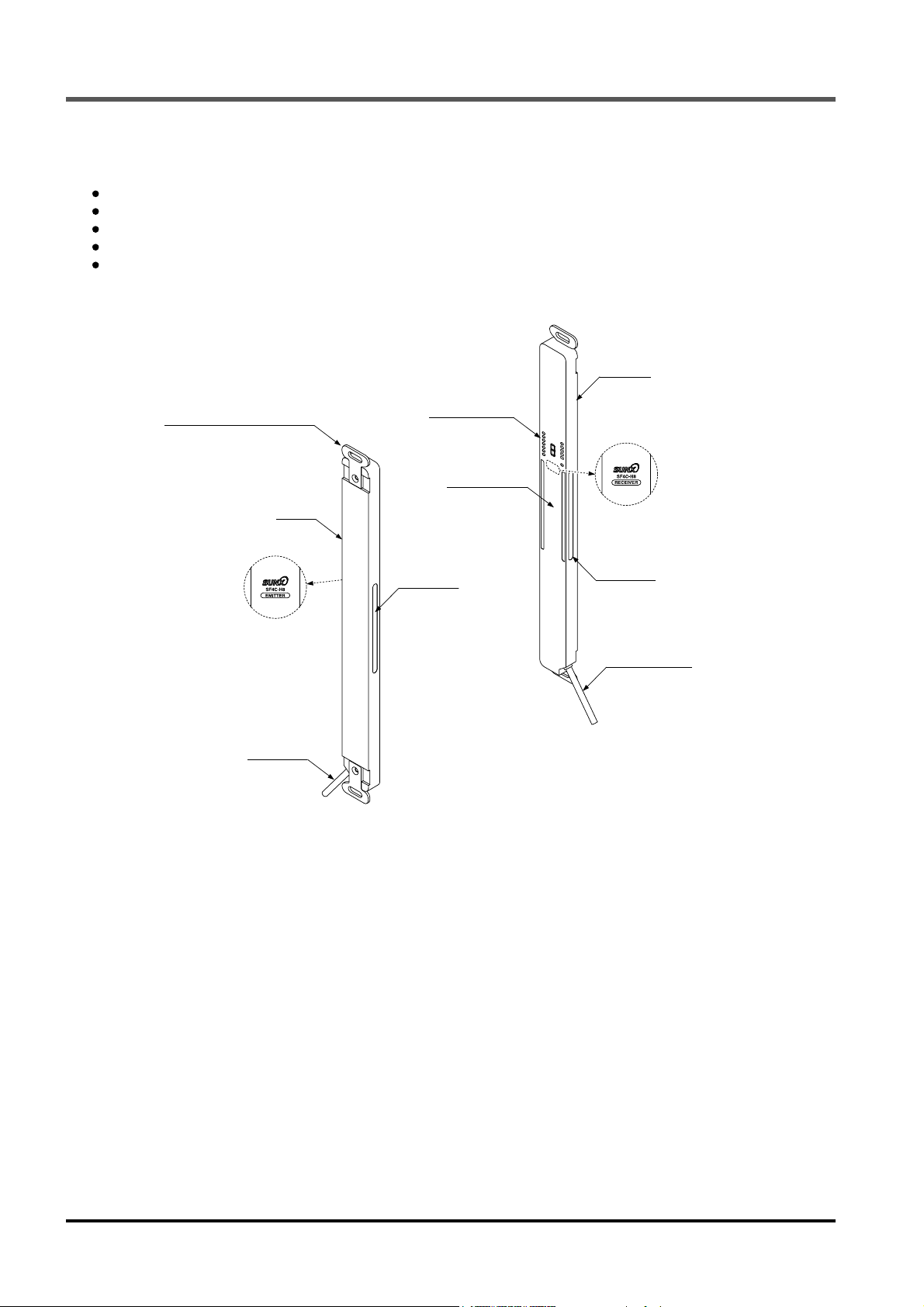
2-2 Part Description
6-2 Options
” for details of options.
Receiver
Standard mounting bracket
MS-SFC-1
(Accessory)
Emitter
Model
information
Gray cable
Display section
Beam-channel
Large multi
-purpose
indicator
Model
information
Large multi
-purpose
indicator
Gray cable
(with black line)
<Emitter>
It emits light to the receiver facing it. Furthermore, the status of the emitter and the receiver is indicated on its
display section.
<Receiver>
It receives light from the emitter facing it. Simultaneously, it turns ON the control output (OSSD 1 / 2) when
the all beam channels receive light from emitter, and it turns OFF the control output (OSSD 1 / 2) when one
or more beam channels are blocked light. [Except when using the muting function (Note 1).]
Besides, the receiver displays its status on the display section.
Notes: 1) In case of using the muting function, muting sensors are required. Furthermore, incase desiring muting lamp, arrange them
separately.
<Beam channel>
The light emitting elements of the emitter and the light receiving elements of the receiver are placed at the
intervals of 20mm.
<Standard mounting bracket MS-SFC-1 (Accessory)>
The mounting brackets are attached to this device.
This brackets are to be used for mounting both emitter and receiver.
9 SUNX Limited MJE-SF4C No.0011-08V
Page 11
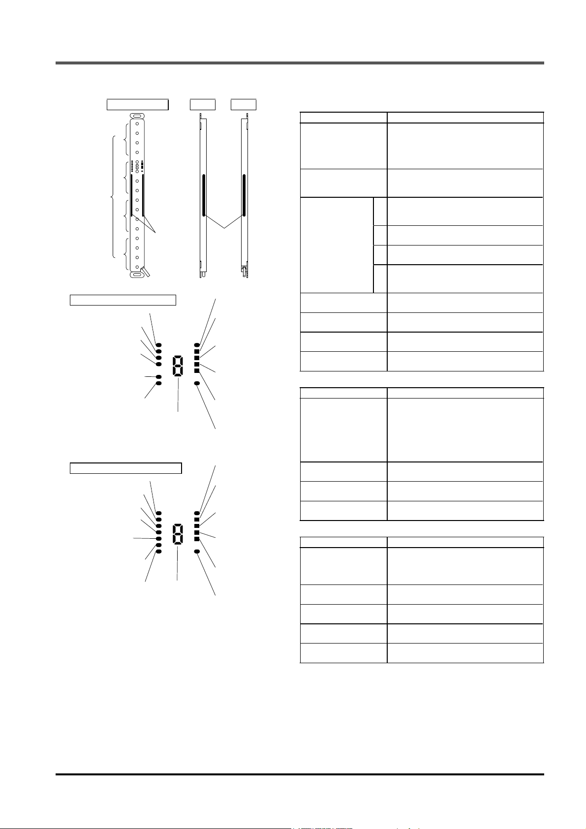
Functional Description
<Indicator section>
Beam-axis side
A
Location of
Beam-axis
alignment
indicator
Indicator section of emitter
Fault indicator [FAULT]
PNP indicator [PNP]
NPN indicator [NPN]
Test input indicator
[TEST]
Safety input 1 indicator
[S1]
Safety input 2 indicator
[S2]
Indicator section of receiver
Fault indicator [FAULT]
PNP indicator [PNP]
NPN indicator [NPN]
Function setting indicator
[FUNCTION]
Interlock indicator
[INTERLOCK]
Muting input 1 indicator
[MU1]
Muting input 2 indicator
[MU2]
Notes: 1) “When light is blocked” refers to the status that there exists any object blocking light in the sensing area.
2) Since the color of the operation indicator changes according to ON / OFF status of the control output (OSSD 1 / 2), the opera-
3) The description given in [ ] is marked on the device.
B
C
Large multi
D
tion indicator is marked as “OSSD” on the device.
-purpose
indicator
Digital error
indicator
Digital error
indicator
Front Back
Large
multipurpose
indicator
Incident light intensity
indicator [STB]
Beam-axis alignment
indicator A
[RECEPTION]
Beam-axis alignment
indicator B
[RECEPTION]
Beam-axis alignment
indicator C
[RECEPTION]
Beam-axis alignment
indicator D
[RECEPTION]
Operation indicator
[OSSD]
Incident light intensity
indicator [STB]
Beam-axis alignment
indicator A
[RECEPTION]
Beam-axis alignment
indicator B
[RECEPTION]
Beam-axis alignment
indicator C
[RECEPTION]
Beam-axis alignment
indicator D
[RECEPTION]
OSSD indicator
[OSSD]
<Common to emitter and receiver>
Description Function
Large multi-purpose
indicator
(Red / Green)
Incident light intensity
indicator
(Green / Orange) [STB]
Beam-axis alignment indicator
(Red / Green)
[RECEPTION]
Digital error indicator
(Red)
Fault indicator (Yellow)
[FAULT]
PNP indicator (Orange)
[PNP]
NPN indicator (Orange)
[NPN]
Lights up in red when the large multipurpose indicator input is valid.
Lights up in green when the large multipurpose indicator input is valid.
Turns OFF when the input is invalid.
Lights up in green when stable light is received.
Lights up in orange when unstable light is received.
Turns OFF when light is blocked. (Note 1)
Lights up in red when device top receives light.
A
Blinks in red when device top end receives light.
Lights up in green when control output (OSSD 1 / 2) is ON.
Lights up in red when device upper middle receives light.
B
Lights up in green when control output (OSSD 1 / 2) is ON.
Lights up in red when device lower middle receives light.
C
Lights up in green when control output (OSSD 1 / 2) is ON.
Lights up in red when device bottom receives light.
D
Blinks in red when device bottom end receives light.
Lights up in green when control output (OSSD 1 / 2) is ON.
Error contents are indicated when device is
lockout.
Lights up or blinks when fault occurs in the
device.
Lights up when PNP output is set.
Lights up when NPN output is set.
<Emitter>
Description Function
Lights up when device operation is as follows.
Operation indicator
(Red / Green) [OSSD]
(Note 2)
Test input indicator
(Orange) [TEST]
Safety input 1 indicator
(Orange) [S1]
Safety input 2 indicator
(Orange) [S2]
[sequential operation to control output
(OSSD 1 / 2)]
Lights up in red when control output (OSSD
1 / 2) is OFF.
Lights up in green when control output
(OSSD 1 / 2) is ON.
Lights up when test input is valid.
Turns OFF when test input is invalid.
Lights up when safety input 1 is valid.
Turns OFF when safety input 1 is invalid.
Lights up when the safety input 2 is valid.
Turns OFF when the safety input 2 is invalid.
<Receiver>
Description Function
OSSD indicator
(Red / Green) [OSSD]
Function setting indicator
(Orange) [FUNCTION]
Interlock indicator
(Yellow) [INTERLOCK]
Muting input 1 indicator
(Orange) [MU1]
Muting input 2 indicator
(Orange) [MU2]
Lights up in red when control output (OSSD
1 / 2) is OFF.
Lights up in green when control output
(OSSD 1 / 2) is ON.
Turns OFF
Lights up when interlock is valid.
Turns OFF
Lights up when muting input 1 is valid.
Turns OFF when muting input 1 is invalid.
Lights up when muting input 2 is valid.
Turns OFF when muting input 2 is invalid.
when interlock is invalid.
10SUNX Limited MJE-SF4C No.0011-08V
Page 12
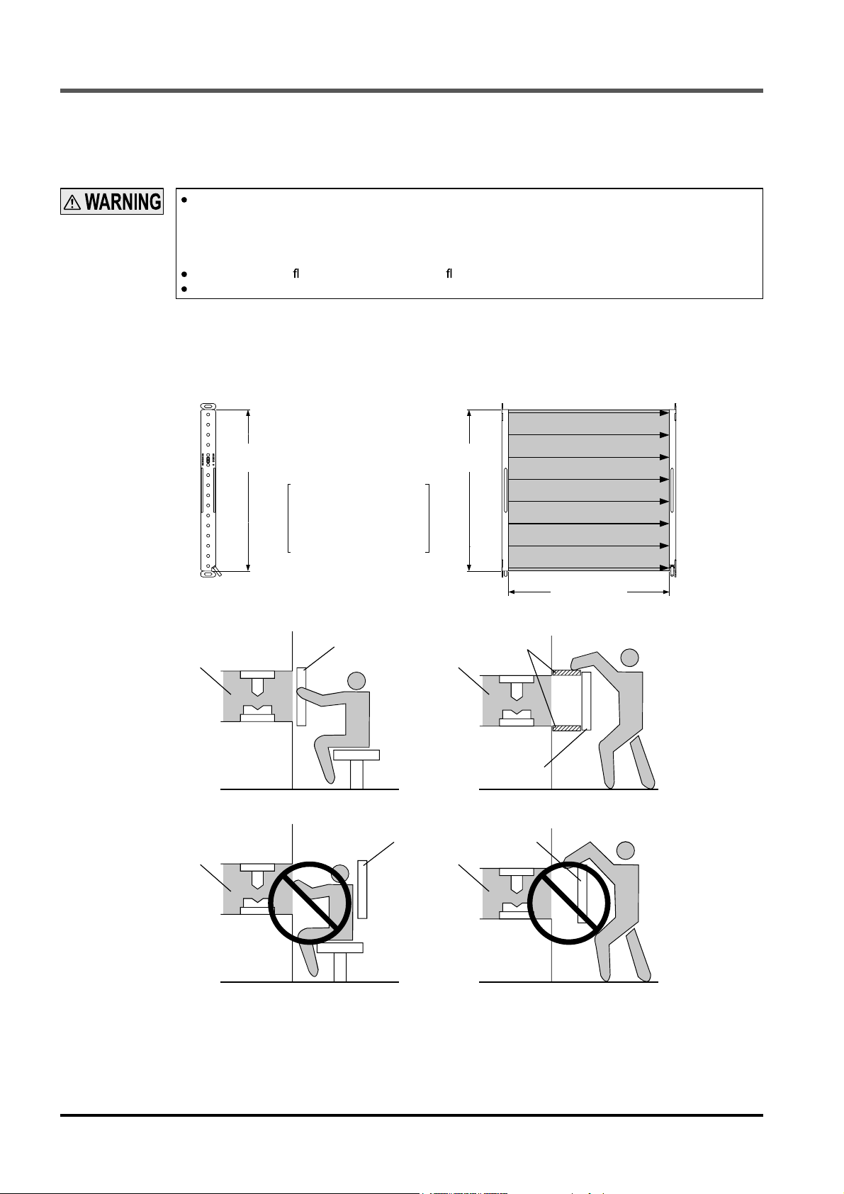
Protection Area
2-3 Protection Area
2-3-1 Sensing Area
Be sure to install protection structure around the machine so that the operator must pass through the
sensing area of this device to reach the dangerous parts of the machine.
Furthermore, ensure that some part of the operator’s body always remains in the sensing area when
operation is done with the dangerous parts of the machine. Failure to do so can result in death or
serious injury.
Do not use any re ection type or recursive re ection type arrangement.
Furthermore, never use this device facing several receivers towards one emitter or vice versa.
The sensing area is the zone formed by the sensing height (protective height) of the device and the valid
range between the emitter and the receiver. The sensing height (protective height) is determined by the number of beam channels. Furthermore, the valid range can be 0.1 to 3m.
Take care that if the valid range is under 0.1m, malfunction may occur due to the optical structure.
Emitter Receiver
To p
Sensing height
(Protective height)
The sensing height (protective height) is the area
between the line indicated
in the top part and line indicated in the bottom part.
Bottom
<Example of correct installation>
Dangerous
part
<Example of incorrect installation>
Dangerous
part
Sensing
area
Sensing height
(Protective height)
Protective structure
Dangerous
part
Sensing area
Sensing area Sensing
Dangerous
part
area
Sensing area
Valid range
11 SUNX Limited MJE-SF4C No.0011-08V
Page 13
Protection Area
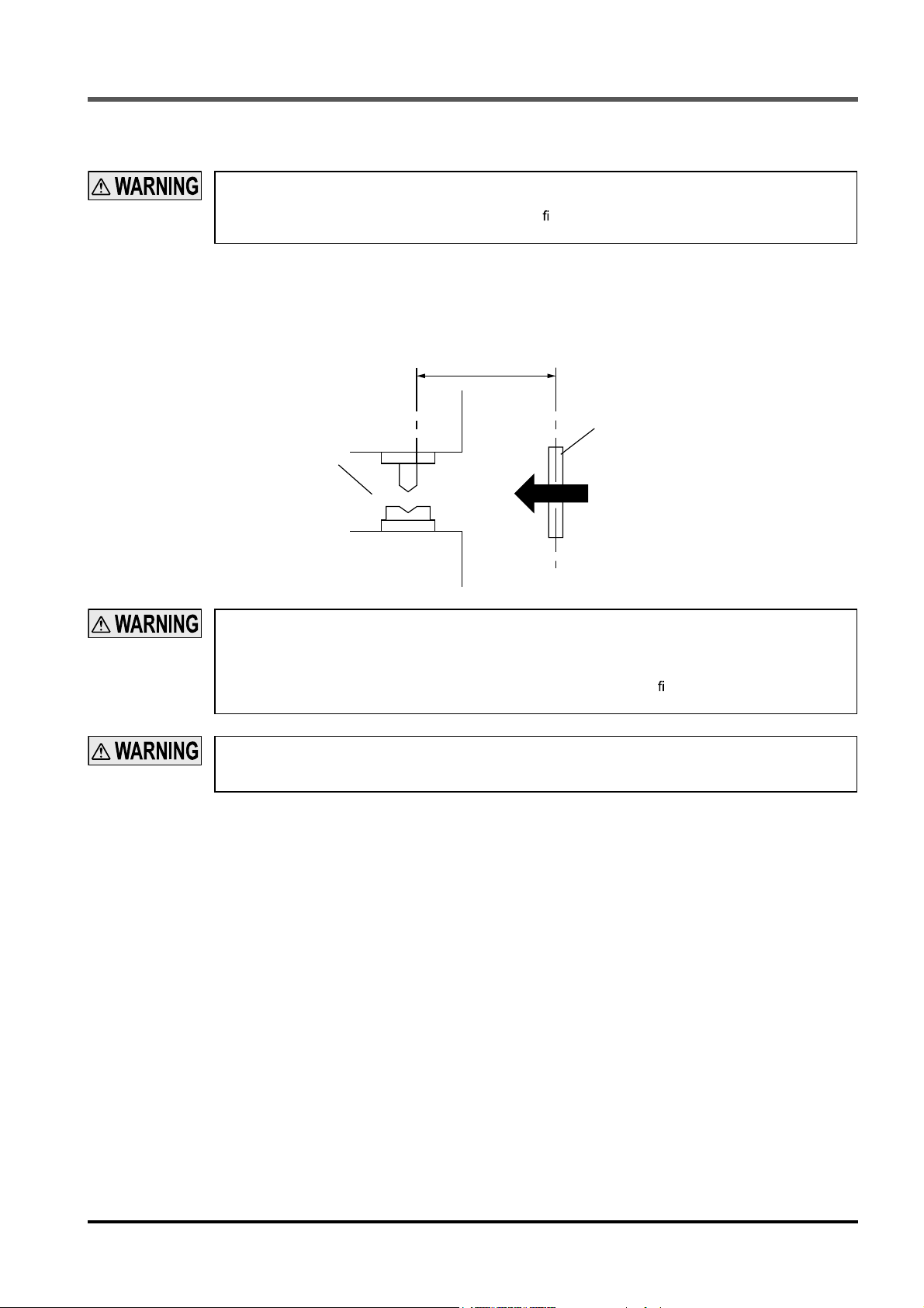
2-3-2 Safety Distance
Calculate the safety distance correctly, and always maintain the distance which is equal to or greater
than the safety distance, between the sensing area of this device and the dangerous parts of the machine. If the safety distance is miscalculated or if suf cient distance is not maintained, the machine will
not stop quickly before reaching to the dangerous parts, which can result in death or serious injury.
The safety distance is the minimum distance that must be maintained between this device and the dangerous parts of the machine so that the machine can be stopped before a human body or an object can reach
the dangerous parts.
The safety distance is calculated based on the equation described in the next page when a person moves
perpendicular (normal intrusion) to the sensing area of the device.
Safety distance S
Sensing area
Dangerous
part
Intrusion direction
Before designing the system, refer to the relevant standards of the region where this device is to be
used, and then install this device.
Furthermore, the equation described in the next pages is to be used only in case the intrusion direction
is perpendicular to the sensing area. In case the intrusion direction is not perpendicular to the sensing
area, be sure to refer to the relevant standard (regional standard, speci cation of the machine, etc.) for
details of the calculation.
The max. response time of the machine is from the point that the machine receives the halt signal from
this device to the point that the dangerous parts of the machine stops. The max. response time of the
machine should be timed with the machine to be actually used.
12SUNX Limited MJE-SF4C No.0011-08V
Page 14

Protection Area
[For use in Europe (EU) (as EN 999)] (Also applicable to ISO 13855 / JIS B9715)
(For intrusion direction perpendicular to the sensing area)
<In case that the minimum sensing object is ø40mm or less>
Equation 1 S = K × T + C
S : Safety distance (mm)
Minimum required distance between the sensing area surface and the dangerous parts of the
machine
K : Intrusion velocity of operator’s body or object (mm/sec.)
Taken as 2,000 (mm/sec.) for calculation.
T
: Response time of total equipment (sec.)
m
T = T
Tm: Maximum halting time of machine (sec.)
T
SF4C
C : Additional distance calculated from the size of the minimum sensing object of the device (mm)
However, the value of C cannot be under 0.
C = 8 × (d
d: Minimum sensing object diameter (mm)
<Reference>
For calculating the safety distance S, there are the following ve cases.
First, calculate by substituting the value K = 2,000 (mm/sec.) in the equation above. Then, classify the obtained value
of S into three cases, 1) S < 100, 2) 100 S 500, and 3) S > 500. For Case 3) S > 500, recalculate by substituting
the value K = 1,600 (mm/sec.). After that, classify the calculation result into two cases, 4) S 500 and 5) S > 500.
For details, refer to “Calculation example 1 For use in Europe.”
When this device is used in the “PSDI mode,” an appropriate safety distance S must be calculated.
For details, be sure to refer to the standards or regulations applicable in each region or country.
SF4C
+ T
: Response time of this device (sec.)
-
14)
<In case that the minimum sensing object is over ø40mm>
Equation 1 S = K × T + C
S : Safety distance (mm)
Minimum required distance between the sensing area surface and the dangerous parts of the
machine
K : Intrusion velocity of operator’s body or object (mm/sec.)
Taken as 1,600 (mm/sec.) for calculation.
T
: Response time of total equipment (sec.)
m
T = T
+ T
SF4C
Tm: Maximum halting time of machine (sec.)
SF4C
T
: Response time of this device (sec.)
C : Additional distance calculated from the size of the minimum sensing object of the device (mm)
C = 850 (mm)
13 SUNX Limited MJE-SF4C No.0011-08V
Page 15

<Calculation example>
Calculation example 1: For use in Europe
(OFF response time: 7ms or less, minimum sensing object diameter: 25mm)
First, calculate with K = 2,000.
S = K × T + C
= K × (T
= 2,000 × (T
= 2,000 × T
= 2,000 × T
= 2,000 × T
m
+ T
SF4C
) + 8 × (d -14)
m
+ 0.007) + 8 × (25 -14)
m
+ 2,000 × 0.007 + 8 × 11
m
+ 14 + 88
m
+ 102
If the result is:
1) In case S < 100 (mm)
Safety distance S is taken as 100 (mm)
2) In case 100 S 500 (mm)
Safety distance S is taken as 2,000 × Tm + 102 (mm)
3) In case S > 500 (mm)
m
S = K’× (T
= 1,600 × (T
= 1,600 × T
= 1,600 × T
= 1,600 × T
SF4C
+ T
) + 8 × (d -14)
m
+ 0.007) + 8 × (25 -14)
m
+ 1,600 × 0.007 + 8 × 11
m
+ 11.2 + 88
m
+ 99.2
Protection Area
then, calculate again.
If the result is:
4) In case S 500 (mm)
Safety distance S is taken as 500 (mm)
5) In case S > 500 (mm)
Safety distance S is taken as 1,600 × T
m
+ 99.2 (mm)
In case this device is installed in a system with a maximum halting time 0.1 (sec.)
S = 2,000 × T
m
+ 102
= 2,000 × 0.1 + 102
= 302
Since this value matches with the case 2) above, S is 302 (mm).
In case this device is installed in a system with a maximum halting time 0.4 (sec.)
S
= 2,000 × T
m
+ 102
= 2,000 × 0.4 + 102
= 902
Since this value matches with the case 3) above,
S = 1,600 × T
m
+ 99.2
= 1,600 × 0.4 + 99.2
= 739.2
Since this value matches with the case 5) above, S is 739.2 (mm).
14SUNX Limited MJE-SF4C No.0011-08V
Page 16

Protection Area
[For use in the United States of America (as per ANSI/RIA 15.06)]
Equation 2 DS = K × (TS + TC + T
DS : Safety distance (mm)
Minimum required distance between the sensing area surface and the dangerous parts of the
machine
K : Intrusion speed {Recommended value in OSHA is 63 (inch/sec.) [ 1,600 (mm/sec.)]}
ANSI/RIA 15.06 does not de ne the intrusion speed “K”. When determining K, consider pos-
sible factors including physical ability of operators.
S
: Halting time calculated from the operation time of the control element (air valve, etc.) (sec.)
T
T
C
: Maximum response time of the control circuit required for functioning the brake (sec.)
SF4C
T
: Response time of this device (sec.)
bm
T
: Additional halting time tolerance for the brake monitor (sec.)
The following equation holds when the machine is equipped with a brake monitor.
T
bm
= Ta-
(TS + TC)
Ta: Setting time of brake monitor (sec.)
When the machine is not equipped with a brake monitor, it is recommended that 20% or more
S
of (T
+ TC) is taken as additional halting time.
pf
D
: Additional distance calculated from the size of the minimum sensing object of the device (mm)
D
pf
= 61.2mm
pf
D
= 3.4 × (d - 0.276) (inch)
-
3.4 × (d
7) (mm)
d: Minimum sensing object diameter 0.985 (inch) 25 (mm)
SF4C
+ Tbm) + D
pf
<Reference>
Since the calculation above is performed by taking 1 (inch) = 25.4 (mm), there is a slight difference between the representation in (mm) and that in (inch).
Refer to the relevant standard for the details.
<Calculation example>
Calculation example 2: For use in the United States of America
[OFF response time: 7ms or less, minimum sensing object diameter: 0.985 (inch) 20 (mm)]
S = K × (TS + TC + T
SF4C
+ Tbm) + D
pf
= 63 × (Ta + 0.007) + 3.4 × (d - 0.276) (inch)
a
= 63 × (T
= 63 × T
= 63 × T
= 63 × T
63 × T
+ 0.007) + 3.4 × (0.985 - 0.276)
a
+ 63 × 0.007 + 3.4 × 0.709
a
+ 0.441 + 2.4106
a
+ 2.8516
a
+ 2.85 (inch)
In case this device is installed in a system with a maximum halting time 0.1 (sec.)
S = 63 × T
a
+ 2.85
= 63 × 0.1 + 2.85
= 9.15 (inch)
232.41 (mm)
Hence, as per the calculations S is 232.4 (mm).
<Reference>
Since the calculation above is performed by taking 1 (inch) = 25.4 (mm), there is a slight difference between the representation in (mm) and that in (inch).
Refer to the relevant standard for the details.
15 SUNX Limited MJE-SF4C No.0011-08V
Page 17
Protection Area
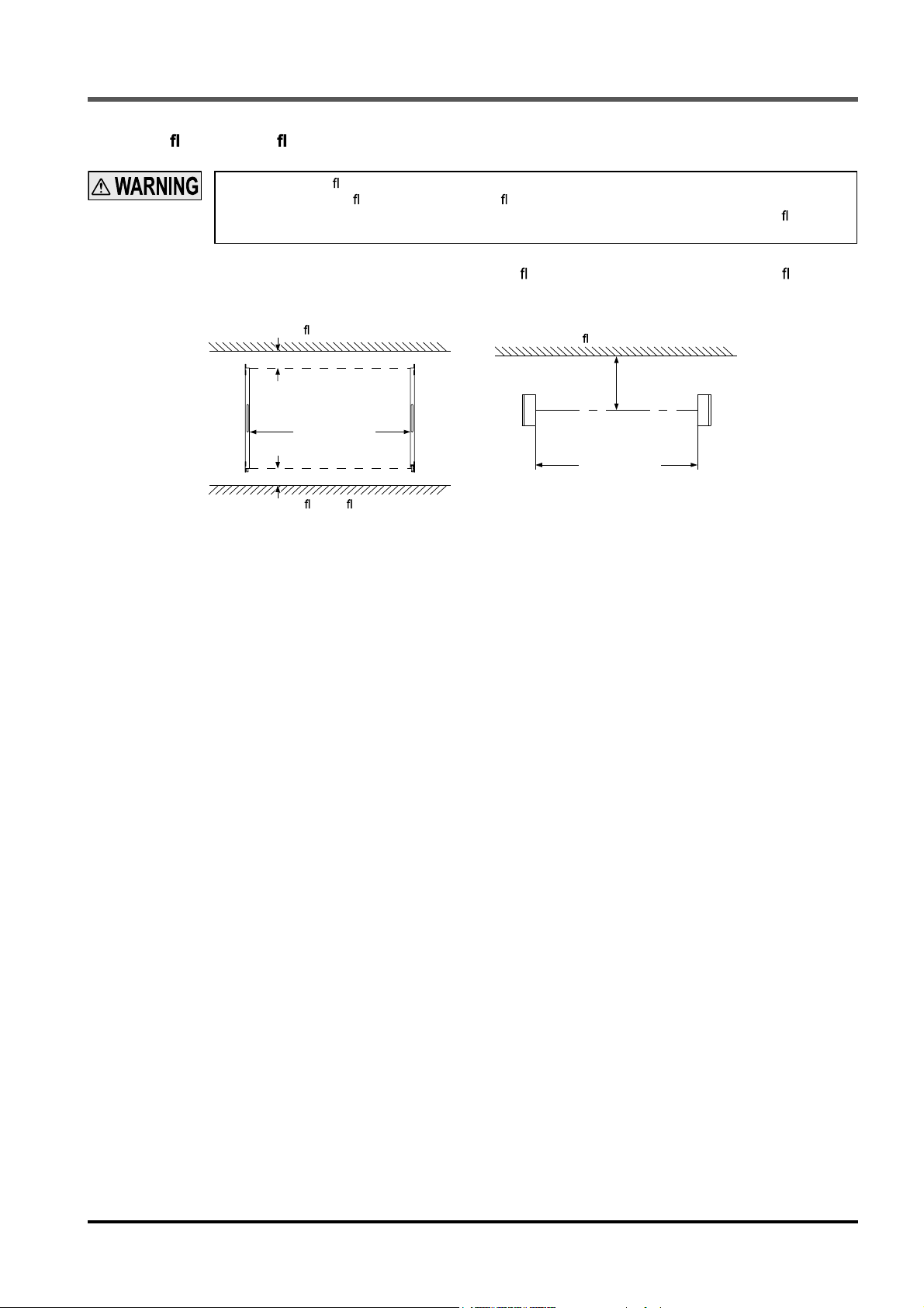
2-3-3 In uence of Re ective Surfaces
If there exists a re ective surface in the place where this device is to be installed, make sure to install
this device so that re ected light from the re ective surface does not enter into the receiver, or take
countermeasures such as painting, masking, roughening, or changing the material of the re ective surface, etc. Failure to do so may cause the device not to detect, resulting in death or serious injury.
Install this device at a distance of at 0.16m or more from re ective surfaces such as metal walls, oors, ceilings, sensing objects, covers, panels or glass surfaces.
<Side view>
Re ective ceiling
Emitter Receiver
0.16m
Sensing range
0.1 to 3m
0.16m
Re ective oor
Emitter Receiver
<Top view>
Re ective surface
0.16m
Sensing range
0.1 to 3m
16SUNX Limited MJE-SF4C No.0011-08V
Page 18
Protection Area
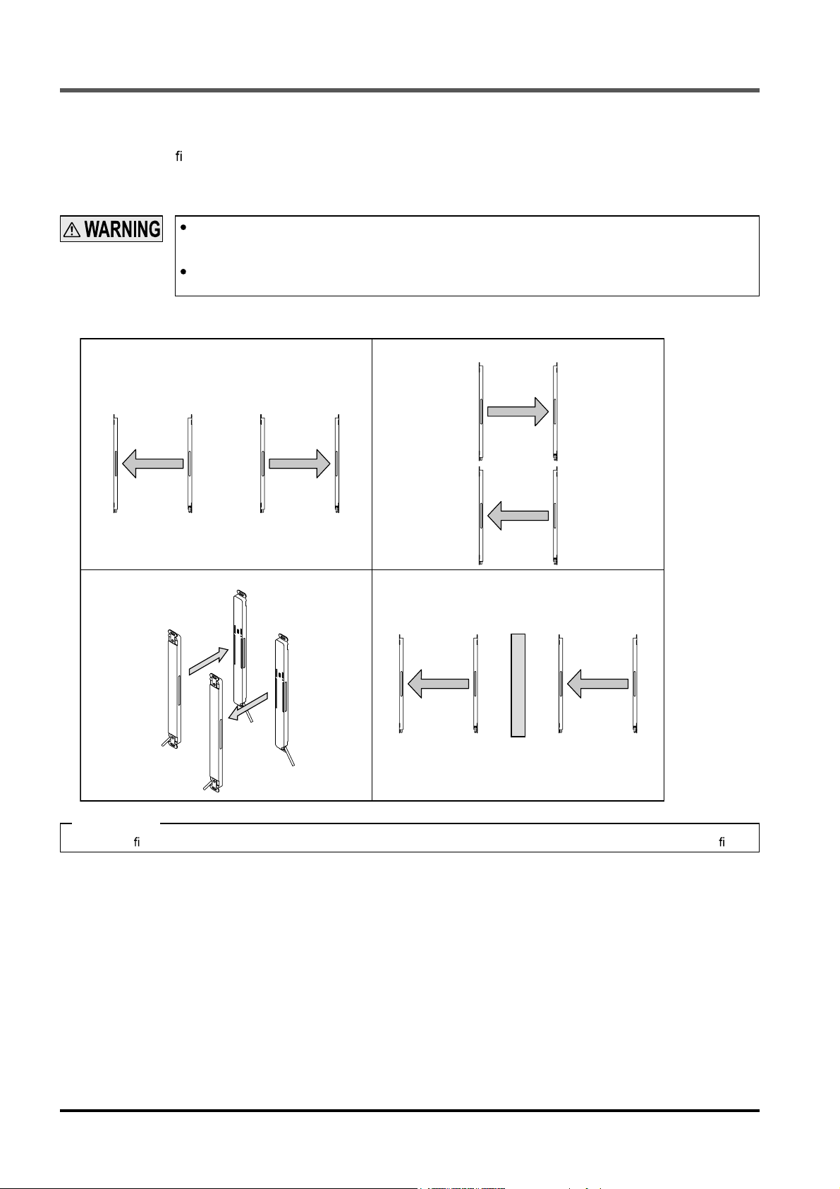
2-3-4 Device Placement
This is the con guration when two or more sets of emitter and receiver facing each other are placed. It is
used for system evaluation in case of addition of equipment. Perform an operation test by referring to “
Operation Test
<Example of device placement>
.”
Refer to the examples of device placement given below and understand them thoroughly before installing the devices.
Improper sensor placement could cause device malfunction, which can result in death or serious injury.
If this device is used in multiple sets, arrange them to avoid mutual interference.
If mutual interference occurs, it can result in death or serious injury.
2-6-2
1) Install the emitter and the receiver back to back.
Receiver Emitter Emitter Receiver
3) Arrange the emitter and the receiver horizontally on
opposite sides.
Emitter
Receiver
Emitter
2) Arrange the emitter and the receiver vertically on
opposite sides.
Emitter
Receiver
4) Install a barrier
Receiver Emitter Receiver Emitter
Barrier
Receiver
Emitter
Receiver
<Reference>
The above gures are just examples of device placement. If there are any questions or problems, please contact our of ce.
17 SUNX Limited MJE-SF4C No.0011-08V
Page 19
Mounting
2-4 Mounting
2-4-1 Mounting of the Mounting Bracket
Do not apply the load such as forced bending to the cable of this device. Applying improper load
could cause the wire breakage.
The minimum bending radius of the cable is R6mm. Mount the device with considering the cable
bending radius.
<Reference>
Mount the emitter and the receiver at the same level and parallel to each other. The effective aperture angle of this device is ±2.5° or less at a sensing distance of 3m.
Unless otherwise speci ed, the following mounting procedure is common for both emitter and receiver. For the preparation of the mounting, prepare the mounting holes on the mounting surface by referring to “
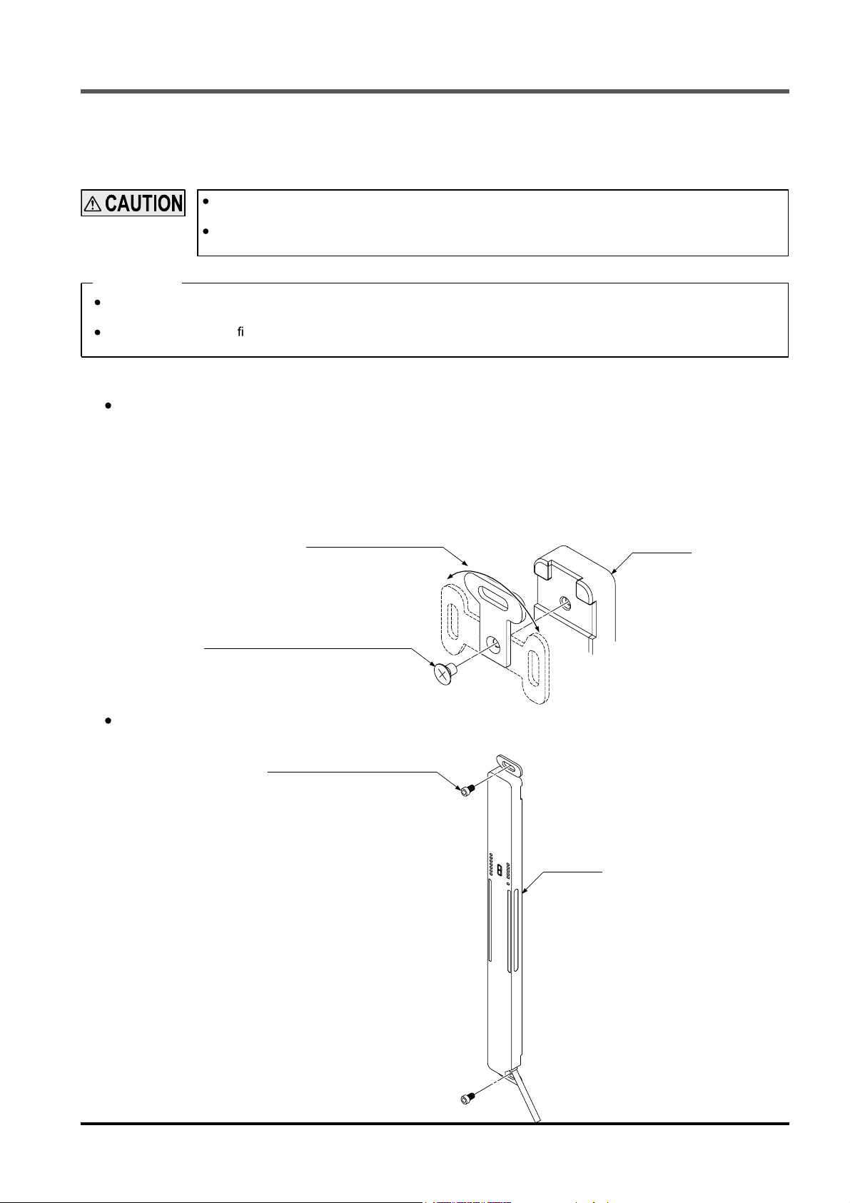
<In case of using standard mounting bracket MS-SFC-1 (Accessory)>
Direction of the standard mounting bracket
MS-SFC-1
which is attached to this device can be changed de-
pending on the mounting position of the device.
1. Remove the M3 countersunk head screw [with anti-loosening agent (length 4mm)] which is attached to the
back of the device.
2 Decide the direction of the standard mounting bracket.
3. Tighten with the M3 countersunk head screw [with anti-loosening agent (length 4mm)].
The tightening torque should be 0.3 N·m.
Standard mounting bracket
MS-SFC-1
(Accessory)
Mountable in three directions
6-3 Dimensions
This device
.”
M3 countersunk head screw
[With anti-loosening agent (length 4mm)]
Install the standard mounting brackets in the mounting surface with two hexagon-socket head bolts
[M5 (please arrange separately)].
Hexagon-socket head bolt
[M5 (Please arrange separately.)]
This device
18SUNX Limited MJE-SF4C No.0011-08V
Page 20
Wiring
2-5 Wiring
Earth the machine or the support where the device is mounted on to frame ground (F.G.).
Failure to do so could cause the malfunction of the product by noise, resulting in death or serious
injury. Furthermore, the wiring should be done in a metal box connected to the frame ground (F.G.).
Take countermeasure against the system to be applied for this device so as not to carry out the dangerous performance caused by the earth failure.
Failure to do so could cause invalid for the system stop, resulting in death or serious injury.
In order that the output is not turned ON due to earth fault of the control output (OSSD 1 / 2) wires,
be sure to ground to 0V side (PNP output) / +V side (NPN output).
Make sure to insulate the ends of the unused lead wires.
<Reference>
Use a safety relay unit or an equivalent control circuit in safety for FSD.
2-5-1 Power Supply Unit
Wire correctly using a power supply unit which conforms to the laws and standards of the region where
this device is to be used.
If the power supply unit is non-conforming or the wiring is improper, it can cause damage or malfunction of this device.
<Reference>
A specialist who has the required electrical knowledge should perform the wiring.
The power supply unit must satisfy the conditions given below.
1) Power supply unit authorized in the region where this device is to be used.
2) Power supply unit SELV (safety extra low voltage) / PELV (protected extra low voltage) conforming to EMC Directive and Low-voltage Directive (only for requiring CE marking conformation).
3) Power supply unit conforming to the Low-voltage Directive and with an output of 100VA or less.
4) The frame ground (F.G.) terminal must be connected to the ground when using a commercially available
switching regulator.
5) Power supply unit with an output holding time of 20ms or more.
6) In case a surge is generated, take countermeasures such as connecting a surge absorber to the origin of the
surge.
7) Power supply unit corresponding to CLASS 2 (only for requiring cTUVus Mark conformation).
19 SUNX Limited MJE-SF4C No.0011-08V
Page 21
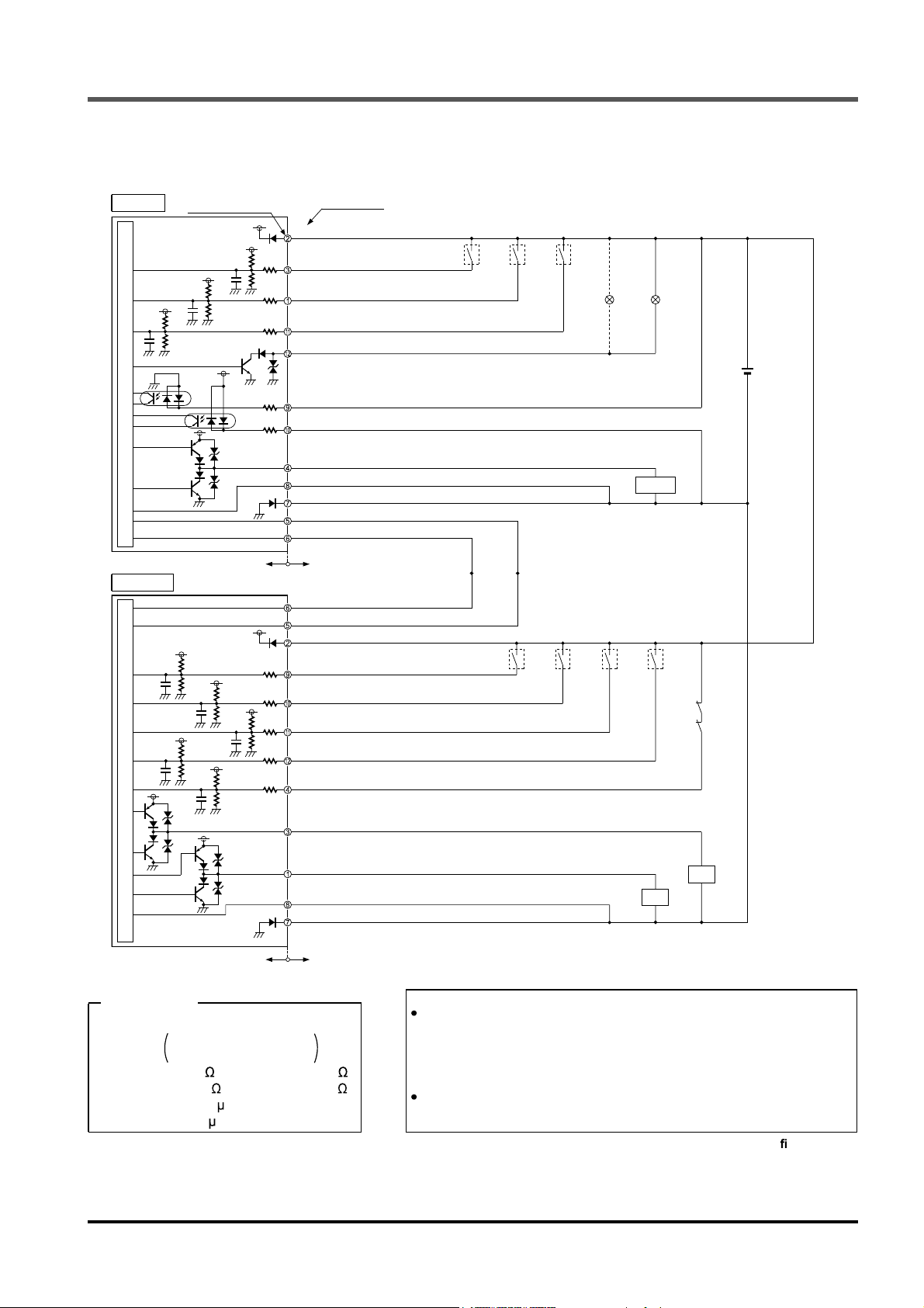
2-5-2 I/O Circuit Diagrams and Output Waveform
<For PNP output>
Emitter
E
Main circuit
Terminal No. of
pigtailed type
E
B
B
B
C
B
E
B
B
C
C
A
A
Color code
(Brown) +V
(Pink) Test input / Reset input
(Pale purple) Interlock setting input
(Yellow) Override input
(Red) Muting lamp output
(Gray) Safety input 1 (Note 1)
(Gray / Black) Safety input 2 (Note 1)
(Yellow-green / Black) Auxiliary output
(Shield) Output polarity setting wire
(Blue) 0V
(Orange) Synchronization +
(Orange / Black) Synchronization -
*S1 *S2 *S2
Load
+
-
Wiring
24V DC
±10%
Users’ circuitInternal circuit
Receiver
D
F
D
D
D
F
B
B
F
Main circuit
E
B
F
B
B
<Reference>
K1, K2: External device
Forced guided relay or
magnetic contactor
Resistance A: 3k , Resistance B: 6.8k
Resistance C: 470 , Resistance D: 47k
Condenser E: 0.47 F
Condenser F: 0.1 F
Notes 1) For wiring of the safety input 1 wire (gray) and the safety input 2 wire (gray / black), refer to “
2)
3) Vs is the applying supply voltage.
Valid Safety Input Function
Large multi-purpose indicator lights up in red when connecting large multi-purpose indicator input 1 wire (grey) and +V, and large
multi-purpose indicator lights up in green when connecting large multi-purpose indicator input 2 wire (grey / black) and +V.
(Orange / Black)
Synchronization
(Orange) Synchronization +
(Brown) +V
(Gray) Large multi-purpose
C
indicator input 1 (Note 2)
C
(Gray / black) Large multi-purpose indicator input 2 (Note 2)
C
(Sky-blue / White) Muting input 1
B
C
(Sky-blue / Black) Muting input 2
C
(Yellow-green) External device monitor input
(Black) Control output 1 (OSSD 1)
(White) Control output 2 (OSSD 2)
(Shield) Output polarity setting wire
(Blue) 0V
Users’ circuitInternal circuit
.”
-
*S1, S2
Switch S1
Test input / Reset input
For manual reset: Vs to Vs - 3.5V (sink current 5mA or less): OFF (Note 3)
Open: ON
For auto reset: Vs to Vs - 3.5V (sink current 5mA or less): ON (Note 3)
Open: OFF
Switch S2
Override input, Interlock setting input, Large multi-purpose indicator input 1 / 2,
Muting input 1 / 2 and External device monitor input
Vs to Vs - 3.5V (sink current 5mA or less): Valid (Note 3), Open: Invalid
*S2 *S2 *S2 *S2
K2
K1
K2
K1
2-5-7 Wiring Con guration for
20SUNX Limited MJE-SF4C No.0011-08V
Page 22
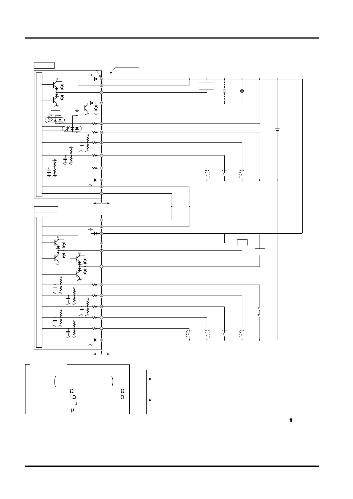
Wiring
<For NPN output>
Emitter
Main circuit
E
B
BE
Terminal No. of
pigtailed type
B
B
E
B
B
Color code
(Brown) +V
(Shield) Output polarity setting wire
(Yellow-green / Black) Auxiliary output
(Red) Muting lamp output
A
(Gray) Safety input 1 (Note 1)
A
(Gray / Black) Safety input 2 (Note 1)
C
(Pink) Test input / Reset input
C
(Pale purple) Interlock setting input
C
(Yellow) Override input
(Blue) 0V
(Orange) Synchronization +
(Orange / Black) Synchronization -
Load
*S2 *S2 *S1
+
-
24V DC
±10%
Internal circuit
Receiver
B
B
E
Main circuit
F
D
F
B
B
B
F
Internal circuit
D
D
D
F
B
<Reference>
K1, K2: External device
Forced guided relay or
magnetic contactor
Resistance A: 3k , Resistance B: 6.8k
Resistance C: 470 , Resistance D: 47k
Condenser E: 0.47 F
Condenser F: 0.1 F
Notes 1) For wiring of the safety input 1 wire (gray) and the safety input 2 wire (gray / black), refer to “
2)
Valid Safety Input Function
Large multi-purpose indicator lights up in red when connecting large multi-purpose indicator input 1 wire (grey) and 0V, and large
multi-purpose indicator lights up in green when connecting large multi-purpose indicator input 2 wire (grey / black) and 0V.
Users’ circuit
(Orange / Black)
Synchronization
(Orange) Synchronization +
(Brown) +V
(Shield) Output polarity setting wire
(Black) Control output 1 (OSSD 1)
(White) Control output 2 (OSSD 2)
C
(Yellow-green) External device monitor input
C
(Gray) Large multi-purpose indicator input 1 (Note 2)
C
(Gray / Black) Large multi-purpose indicator input 2 (Note 2)
C
(Sky-blue / White) Muting input 1
C
(Sky-blue / Black) Muting input 2
(Blue) 0V
Users’ circuit
.”
-
*S2 *S2 *S2 *S2
*S1, S2
Switch S1
Test input / Reset input
For manual reset: 0 to +2.5V (source current 5mA or less): OFF, Open: ON
For auto reset: 0 to +2.5V (source current 5mA or less): ON
Switch S2
Override input, Interlock setting input, Large multi-purpose indicator input 1 / 2,
Muting input 1 / 2 and External device monitor input
0 to +2.5V (source
current 5mA or less): Valid, Open: Invalid
K1
K2
K1
K2
,
Open: OFF
2-5-7 Wiring Con guration for
21 SUNX Limited MJE-SF4C No.0011-08V
Page 23

Wiring
<Output waveform [when control output (OSSD 1 / 2) is ON]>
Since the receiver performs the self-diagnosis of the output circuit when the device is in light receiving status
(ON status), the output transistor becomes OFF status periodically. (Refer to the gure below.)
When the OFF signal is fed back, the receiver judges the output circuit as normal. When the OFF signal is
not fed back, the receiver judges either the output circuit or wiring as error, and the control output (OSSD 1 / 2)
maintains OFF status.
Perform the wiring with paying attention to the input response time of the machine to be connected to
this device, since the OFF signal of this device might cause malfunction.
<Time chart>
Power supply
Control output 1
(OSSD 1)
Control output 2
(OSSD 2)
ON
OFF
ON
OFF
ON
OFF
Approx. 2 sec.
Approx. 35 to 60 s
Approx. 2.5ms
Approx. 20 s
Approx. 35 to 60 s
Approx. 35 to 60 s
Approx. 20 s
Approx. 35 to 60 s
22SUNX Limited MJE-SF4C No.0011-08V
Page 24

Wiring
2-5-3 Wiring / Connecting Procedures and Terminal Arrangement
Connect the mating cable (with connector on one end or connector on both ends) to the pigtailed type of this
device (emitter and receiver) according to the customer’s application referring to the terminal arrangement
given below. In addition, in case of the cable type (emitter and receiver) as well, wire the cables according to
the customer’s application referring to the terminal arrangement given below.
When extending the cable, use the exclusive cable up to the total length of 40.5m or less (for each
emitter / receiver). Extending the cable longer than 40.5m may cause malfunction, which can result
in death or serious injury.
In case of using the muting lamp, a total length should be 30.5m or less (for each emitter / receiver).
When the synchronization cable is extended with a cable other than exclusive cable, use a 0.2mm
or more shielded twisted pare cable.
2
<Cable with connector on one end>
A si de
<Terminal arrangement of A side>
Cable / Connector color Terminal No. Color code Description
Emitter Gray / Gray
Receiver Gray (with black line) / Black
<Cable with connector on both ends>
A side B side
<Terminal arrangement of B side><Terminal arrangement of A side>
1 Pale purple Interlock setting input
2Brown +V
3 Pink Test input / Reset input
4 Yellow-green / Black Auxiliary output
5 Orange Synchronization +
6 Orange / Black Synchronization
7Blue 0V
8 (Shield) Output polarity setting wire
9 Gray Safety input 1
10 Gray / Black Safety input 2
11 Yellow Override input
12 Red Muting lamp output
1 White Control output 2 (OSSD 2)
2Brown +V
3 Black Control output 1 (OSSD 1)
4 Yellow-green External device monitor input
5 Orange Synchronization +
6 Orange / Black Synchronization
7Blue 0V
8 (Shield) Output polarity setting wire
9 Gray Large multi-purpose indicator input 1
10 Gray / Black Large multi-purpose indicator input 2
11 Sky-blue / White Muting input 1
12 Sky-blue / Black Muting input 2
-
-
<Reference>
The connectors can be distinguished from their colors as follows:
Connector for emitter: Gray, connector for receiver: Black
For details of the cable with connector on one end and the cable with connector on both ends, refer to “
23 SUNX Limited MJE-SF4C No.0011-08V
6-2 Options
.”
Page 25

Wiring
2-5-4 Basic Wiring
This is the general con guration using one set of the emitter and receiver facing each other. The control output (OSSD 1 / 2) turns OFF if the light is blocked, while it automatically turns ON if receives the light.
The auxiliary output is used to invalid the external device monitor function. The auxiliary output cannot be
connected to external devices.
<For PNP output>
Receiver
Emitter
Grey cable
Grey cable
(with black line)
(Red) Muting lamp output
(Yellow) Override input
(Pale purple) Interlock setting input
(Brown) +V
(Pink) Test input / Reset input
(Gray) Safety input 1
(Gray / Black) Safety input 2
(Shield) Output polarity setting wire
(Blue) 0V
(Yellow-green / Black) Auxiliary output
(Orange) Synchronization +
(Orange / Black) Synchronization (Orange / Black) Synchronization (Orange) Synchronization +
(Yellow-green) External device monitor input
(Brown) +V
(Black) Control output 1 (OSSD 1)
(White) Control output 2 (OSSD 2)
(Shield) Output polarity setting wire
(Blue) 0V
(Sky-blue / White) Muting input 1
(Sky-blue / Black) Muting input 2
(Gray) Large multi-purpose indicator input 1
(Gray / Black) Large multi-purpose indicator input 2
K1
K2
+
-
24V DC
%
Interlock function Invalid (Auto-reset)
External device monitor function Invalid
Auxiliary output Cannot be used
24SUNX Limited MJE-SF4C No.0011-08V
Page 26

Wiring
<For NPN output>
Receiver Emitter
Grey cable
Grey cable
(with black line)
(Red) Muting lamp output
(Yellow) Override input
(Pale purple) Interlock setting input
(Brown) +V
(Shield) Output polarity setting wire
(Pink) Test input / Reset input
(Gray) Safety input 1
(Gray / Black) Safety input 2
(Blue) 0V
(Yellow-green / Black) Auxiliary output
(Orange) Synchronization +
(Orange / Black) Synchronization (Orange / Black) Synchronization (Orange) Synchronization +
(Yellow-green) External device monitor input
(Brown) +V
(Black) Control output 1 (OSSD 1)
(White) Control output 2 (OSSD 2)
(Shield) Output polarity setting wire
(Blue) 0V
(Sky-blue / White) Muting input 1
(Sky-blue / Black) Muting input 2
(Gray) Large multi-purpose indicator input 1
(Gray / Black) Large multi-purpose indicator input 2
K1
K2
+
-
24V DC
%
Interlock function Invalid (Auto-reset)
External device monitor function Invalid
Auxiliary output Cannot be used
25 SUNX Limited MJE-SF4C No.0011-08V
Page 27

Wiring
2-5-5 Wiring for Manual Reset (Interlock is Valid) (Wiring Example of the Control Category 4)
This is the general con guration using one set of the emitter and receiver facing each other. The control output (OSSD 1 / 2) turns OFF if the light is blocked.
<For PNP output>
Receiver Emitter
Grey cable
Grey cable
(with black line)
(Red) Muting lamp output
(Yellow) Override input
(Brown) +V
(Pale purple) Interlock setting input
(Pink) Test input / Reset input
(Gray) Safety input 1
(Gray / Black) Safety input 2
(Yellow-green / Black) Auxiliary output
(Shield) Output polarity setting wire
(Blue) 0V
(Orange) Synchronization +
(Orange / Black) Synchronization (Orange / Black) Synchronization (Orange) Synchronization +
(Yellow-green) External device monitor input
(Brown) +V
(Black) Control output 1 (OSSD 1)
(White) Control output 2 (OSSD 2)
(Shield) Output polarity setting wire
(Blue) 0V
(Sky-blue / White) Muting input 1
(Sky-blue / Black) Muting input 2
(Gray) Large multi-purpose indicator input 1
(Gray / Black) Large multi-purpose indicator input 2
K1
K2
Load
S1
K1 K2
+
-
24V DC
%
Interlock function Valid (Manual reset)
External device monitor function Valid
Auxiliary output Can be used
The device output is selected depending on the connecting state of the output polarity setting wire (shield). Incorrect
wiring may cause the lockout state.
* Symbols
Switch S1
Test input / Reset input
Vs to Vs - 3.5V (sink current 5mA or less): OFF (Note 1), Open: ON
K1, K2: External device (Forced guided relay or magnetic contactor)
Notes: 1) Vs is the applying supply voltage.
2) For resetting, refer to “
3-2 Interlock Function
.”
26SUNX Limited MJE-SF4C No.0011-08V
Page 28

Wiring
<For NPN output>
Receiver Emitter
Grey cable
Grey cable
(with black line)
(Red) Muting lamp output
(Yellow) Override input
(Brown) +V
(Yellow-green / Black) Auxiliary output
(Shield) Output polarity setting wire
(Gray) Safety input 1
(Gray / Black) Safety input 2
(Pink) Test input / Reset input
(Pale purple) Interlock setting input
(Blue) 0V
(Orange) Synchronization +
(Orange / Black) Synchronization (Orange / Black) Synchronization (Orange) Synchronization +
(Yellow-green) External device monitor input
(Brown) +V
(Black) Control output 1 (OSSD 1)
(White) Control output 2 (OSSD 2)
(Shield) Output polarity setting wire
(Blue) 0V
(Sky-blue / White) Muting input 1
(Sky-blue / Black) Muting input 2
(Gray) Large multi-purpose indicator input 1
(Gray / Black) Large multi-purpose indicator input 2
K1
K2
Load
S1
K1 K2
+
-
24V DC
%
Interlock function Valid (Manual reset)
External device monitor function Valid
Auxiliary output Can be used
The device output is selected depending on the connecting state of the output polarity setting wire (shield). Incorrect
wiring may cause the lockout state.
* Symbols
Switch S1
Test input / Reset input
0 to +2.5V (source current 5mA or less): OFF, Open: ON
K1, K2: External device (Forced guided relay or magnetic contactor)
Note: For resetting, refer to “
3-2 Interlock Function
.”
27 SUNX Limited MJE-SF4C No.0011-08V
Page 29

Wiring
2-5-6 Wiring for Auto Reset (Interlock is Invalid) (Wiring Example of the Control Category 4)
<For PNP output>
(Red) Muting lamp output
Receiver Emitter
Grey cable
Grey cable
(with black line)
(Yellow) Override input
(Pale purple) Interlock setting input
(Brown) +V
(Pink) Test input / Reset input
(Gray) Safety input 1
(Gray / Black) Safety input 2
(Yellow-green / Black) Auxiliary output
(Shield) Output polarity setting wire
(Blue) 0V
(Orange) Synchronization +
(Orange / Black) Synchronization (Orange / Black) Synchronization (Orange) Synchronization +
(Yellow-green) External device monitor input
(Brown) +V
(Black) Control output 1 (OSSD 1)
(White) Control output 2 (OSSD 2)
(Shield) Output polarity setting wire
(Blue) 0V
(Sky-blue / White) Muting input 1
(Sky-blue / Black) Muting input 2
(Gray) Large multi-purpose indicator input 1
(Gray / Black) Large multi-purpose indicator input 2
K1
K2
Load
S1
K1 K2
+
-
24V DC
%
Interlock function Invalid (Auto reset)
External device monitor function Valid
Auxiliary output Can be used
The device output is selected depending on the connecting state of the output polarity setting wire (shield). Incorrect
wiring may cause the lockout state.
* Symbols
Switch S1
Test input / Reset input
Vs to Vs - 3.5V (sink current 5mA or less): ON (Note 1), Open: OFF
K1, K2: External device (Forced guided relay or magnetic contactor)
Notes: 1) Vs is the applying supply voltage.
2) For resetting, refer to “
3-2 Interlock Function
.”
28SUNX Limited MJE-SF4C No.0011-08V
Page 30

Wiring
<For NPN output>
Receiver Emitter
Grey cable
Grey cable
(with black line)
(Red) Muting lamp output
(Yellow) Override input
(Pale purple) Interlock setting input
(Brown) +V
(Yellow-green / Black) Auxiliary output
(Shield) Output polarity setting wire
(Gray) Safety input 1
(Gray / Black) Safety input 2
(Pink) Test input / Reset input
(Blue) 0V
(Orange) Synchronization +
(Orange / Black) Synchronization (Orange / Black) Synchronization (Orange) Synchronization +
(Yellow-green) External device monitor input
(Brown) +V
(Black) Control output 1 (OSSD 1)
(White) Control output 2 (OSSD 2)
(Shield) Output polarity setting wire
(Blue) 0V
(Sky-blue / White) Muting input 1
(Sky-blue / Black) Muting input 2
(Gray) Large multi-purpose indicator input 1
(Gray / Black) Large multi-purpose indicator input 2
K1
K2
Load
S1
K1 K2
+
-
24V DC
%
Interlock function Invalid (Auto reset)
External device monitor function Valid
Auxiliary output Can be used
The device output is selected depending on the connecting state of the output polarity setting wire (shield). Incorrect
wiring may cause the lockout state.
* Symbols
Switch S1
Test input / Reset input
0 to +2.5V (source current 5mA or less): ON, Open: OFF
K1, K2: External device (Forced guided relay or magnetic contactor)
Note: For resetting, refer to “
3-2 Interlock Function
.”
29 SUNX Limited MJE-SF4C No.0011-08V
Page 31

Wiring
2-5-7 Wiring Con guration for Valid Safety Input Function
(Wiring Example of the Control Category 4)
The safety contacting point can be connected to safety input 1 wire (gray) and the safety input 2 wire (gray /
black) of the emitter.
Refer to “
<For PNP output>
3-4 Safety Input Function
Safety contacting point
” for detail of safety input function.
This device
Receiver Emitter
Grey cable
Grey cable
(with black line)
Interlock function Invalid (Auto-reset)
External device monitor function Invalid
Auxiliary output Cannot be used
(Gray / Black)
Safety input 2
(Gray) Safety input 1
(Red) Muting lamp output
(Yellow) Override input
(Pale purple) Interlock setting input
(Brown) +V
(Pink) Test input / Reset input
(Shield) Output polarity setting wire
(Blue) 0V
(Yellow-green / Black) Auxiliary output
(Orange) Synchronization +
(Orange / Black) Synchronization (Orange / Black) Synchronization (Orange) Synchronization +
(Yellow-green) External device monitor input
(Brown) +V
(Black) Control output 1 (OSSD 1)
(White) Control output 2 (OSSD 2)
(Shield) Output polarity setting wire
(Blue) 0V
(Sky-blue / White) Muting input 1
(Sky-blue / Black) Muting input 2
(Gray) Large multi-purpose indicator input 1
(Gray / Black) Large multi-purpose indicator input 2
+
24V DC
%
-
K1
K2
Safety input
Short-circuit (sink current 5 to 10mA), Source current 5 to 10mA: Valid
Open: Invalid
30SUNX Limited MJE-SF4C No.0011-08V
Page 32

Wiring
<For NPN output>
Safety contacting point
This device
Receiver Emitter
Grey cable
Grey cable
(with black line)
Interlock function Invalid (Auto-reset)
External device monitor function Invalid
Auxiliary output Cannot be used
(Gray / Black)
Safety input 2
(Gray) Safety input 1
(Red) Muting lamp output
(Yellow) Override input
(Pale purple) Interlock setting input
(Brown) +V
(Pink) Test input / Reset input
(Shield) Output polarity setting wire
(Blue) 0V
(Yellow-green / Black) Auxiliary output
(Orange) Synchronization +
(Orange / Black) Synchronization (Orange / Black) Synchronization (Orange) Synchronization +
(Yellow-green) External device monitor input
(Brown) +V
(Black) Control output 1 (OSSD 1)
(White) Control output 2 (OSSD 2)
(Shield) Output polarity setting wire
(Blue) 0V
(Sky-blue / White) Muting input 1
(Sky-blue / Black) Muting input 2
(Gray) Large multi-purpose indicator input 1
(Gray / Black) Large multi-purpose indicator input 2
+
24V DC
%
-
K1
K2
Safety input
Short-circuit (sink current 5 to 10mA), Source current 5 to 10mA: Valid
Open: Invalid
31 SUNX Limited MJE-SF4C No.0011-08V
Page 33

2-5-8 Wiring Con guration for Invalid External Device Monitor Function
(Wiring Example of the Control Category 4)
This is the con guration for connecting auxiliary output and external device monitor input.
cannot be connected to external devices.
<For PNP output>
(Red) Muting lamp output
Receiver Emitter
Grey cable
Grey cable
(with black line)
(Yellow) Override input
(Pale purple) Interlock setting input
(Brown) +V
(Pink) Test input / Reset input
(Gray) Safety input 1
(Gray / Black) Safety input 2
(Shield) Output polarity setting wire
(Blue) 0V
(Yellow-green / Black) Auxiliary output
(Orange) Synchronization +
(Orange / Black) Synchronization (Orange / Black) Synchronization (Orange) Synchronization +
(Yellow-green) External device monitor input
(Brown) +V
(Black) Control output 1 (OSSD 1)
(White) Control output 2 (OSSD 2)
(Shield) Output polarity setting wire
(Blue) 0V
(Sky-blue / White) Muting input 1
(Sky-blue / Black) Muting input 2
(Gray) Large multi-purpose indicator input 1
(Gray / Black) Large multi-purpose indicator input 2
K1
K2
S1
Wiring
The auxiliary output
+
24V DC
%
-
Interlock function Invalid (Auto reset)
External device monitor function Invalid
Auxiliary output Cannot be used
The device output is selected depending on the connecting state of the output polarity setting wire (shield). Incorrect
wiring may cause the lockout state.
* Symbols
Switch S1
Test input / Reset input
Vs to Vs - 3.5V (sink current 5mA or less): ON (Note), Open: OFF
K1, K2: External device (Forced guided relay or magnetic contactor)
Note: Vs is the applying supply voltage.
32SUNX Limited MJE-SF4C No.0011-08V
Page 34

Wiring
<For NPN output>
Receiver Emitter
Grey cable
Grey cable
(with black line)
(Red) Muting lamp output
(Yellow) Override input
(Pale purple) Interlock setting input
(Brown) +V
(Shield) Output polarity setting wire
(Pink) Test input / Reset input
(Gray) Safety input 1
(Gray / Black) Safety input 2
(Blue) 0V
(Yellow-green / Black) Auxiliary output
(Orange) Synchronization +
(Orange / Black) Synchronization (Orange / Black) Synchronization (Orange) Synchronization +
(Yellow-green) External device monitor input
(Brown) +V
(Black) Control output 1 (OSSD 1)
(White) Control output 2 (OSSD 2)
(Shield) Output polarity setting wire
(Blue) 0V
(Sky-blue / White) Muting input 1
(Sky-blue / Black) Muting input 2
(Gray) Large multi-purpose indicator input 1
(Gray / Black) Large multi-purpose indicator input 2
K1
K2
S1
+
-
24V DC
%
Interlock function Invalid (Auto reset)
External device monitor function Invalid
Auxiliary output Cannot be used
The device output is selected depending on the connecting state of the output polarity setting wire (shield). Incorrect
wiring may cause the lockout state.
* Symbols
Switch S1
Test input / Reset input
0 to +2.5V (source current 5mA or less): ON, Open: OFF
K1, K2: External device (Forced guided relay or magnetic contactor)
33 SUNX Limited MJE-SF4C No.0011-08V
Page 35

2-5-9 Wiring Con guration for Valid Muting Function
(Wiring Example of the Control Category 4)
<For PNP output>
(Pale purple) Interlock setting input
Receiver Emitter
Grey cable
Grey cable
(with black line)
Interlock function Invalid (Auto reset)
External device monitor function Valid
Auxiliary output Can be used
(Brown) +V
(Red) Muting lamp output
(Pink) Test input / Reset input
(Yellow) Override input
(Gray) Safety input 1
(Gray / Black) Safety input 2
(Yellow-green / Black) Auxiliary output
(Shield) Output polarity setting wire
(Blue) 0V
(Orange) Synchronization +
(Orange / Black) Synchronization (Orange / Black) Synchronization (Orange) Synchronization +
(Yellow-green) External device monitor input
(Brown) +V
(Sky-blue / White) Muting input 1
(Sky-blue / Black) Muting input 2
(Black) Control output 1 (OSSD 1)
(White) Control output 2 (OSSD 2)
(Shield) Output polarity setting wire
(Blue) 0V
(Gray) Large multi-purpose indicator input 1
(Gray / Black) Large multi-purpose indicator input 2
(Note 1)
K1
K2
Load
S1
S2
K1 K2
S2
S2
+
-
Wiring
24V DC
%
The device output is selected depending on the connecting state of the output polarity setting wire (shield). Incorrect
wiring may cause the lockout state.
* Symbols
Switch S1
Test input / Reset input
Vs to Vs - 3.5V (sink current 5mA or less): ON (Note 2), Open: OFF
Switch S2
Muting input, Override input
Vs to Vs - 3.5V (sink current 5mA or less): Valid (Note 2), Open: Invalid
K1, K2: External device (Forced guided relay or magnetic contactor)
Notes: 1) The incandescent lamp or LED with total 6W or less shall be used when connecting lamp to the muting lamp output.
2) Vs is the applying supply voltage.
34SUNX Limited MJE-SF4C No.0011-08V
Page 36

Wiring
<For NPN output>
(Pale purple) Interlock setting input
(Brown) +V
Receiver Emitter
Grey cable
Grey cable
(with black line)
Interlock function Invalid (Auto reset)
External device monitor function Valid
Auxiliary output Can be used
(Red) Muting lamp output
(Yellow-green / Black) Auxiliary output
(Shield) Output polarity setting wire
(Gray) Safety input 1
(Gray / Black) Safety input 2
(Yellow) Override input
(Pink) Test input / Reset input
(Blue) 0V
(Orange) Synchronization +
(Orange / Black) Synchronization (Orange / Black) Synchronization (Orange) Synchronization +
(Yellow-green) External device monitor input
(Brown) +V
(Black) Control output 1 (OSSD 1)
(White) Control output 2 (OSSD 2)
(Shield) Output polarity setting wire
(Sky-blue / White) Muting input 1
(Sky-blue / Black) Muting input 2
(Blue) 0V
(Gray) Large multi-purpose indicator input 1
(Gray / Black) Large multi-purpose indicator input 2
(Note)
K1
K2
Load
S1
S2
K1 K2
S2
S2
+
-
24V DC
%
The device output is selected depending on the connecting state of the output polarity setting wire (shield). Incorrect
wiring may cause the lockout state.
* Symbols
Switch S1
Test input / Reset input
0 to +2.5V (source current 5mA or less): ON, Open: OFF
Switch S2
Muting input, Override input
0 to +2.5V (source current 5mA or less): Valid, Open: Invalid
K1, K2: External device (Forced guided relay or magnetic contactor)
Note: The incandescent lamp or LED with total 6W or less shall be used when connecting to lamp the muting lamp output.
35 SUNX Limited MJE-SF4C No.0011-08V
Page 37

Adjustment
2-6 Adjustment
2-6-1 Beam-axis Alignment
1. Turn ON the power supply unit of this device.
2. Check that the digital error indicator (red) and the fault indicator (yellow) of the emitter and the receiver are
OFF respectively.
If the digital error indicator (red) or the fault indicator (yellow) lights up or blinks, refer to “
Troubleshooting
3. Loosen the hexagon-socket head bolts [M5 (please arrange separately)] which holds the standard mounting bracket
4. Move the emitter in the left and right directions in order to determine the range of the light received condition with the help of the beam-axis alignment indicator (red). Then, set the emitter at the center of this
range.
5. Similar to the step 4, perform the beam-axis alignment for the receiver.
MS-SFC-1
” and report the symptoms to the maintenance in charge.
.
Chapter 5
6. Tighten the standard mounting bracket
separately)].
7. Check, once again, that the beam-axis alignment indicators (red), operation indicator (green) and OSSD
indicator (green) in the display of the emitter and receiver do light up.
Receiver
MS-SFC-1
by the hexagon-socket head bolt [M5 (please arrange
Emitter
36SUNX Limited MJE-SF4C No.0011-08V
Page 38

Adjustment
<Reference>
The beam-axis alignment indicator indicates the reception status for each section of the device which is divided into 4
sections.
Furthermore, the A (D) of the beam-axis alignment indicates the light-receiving status of the device top end (bottom end).
For example, when using a 16-beam channel device, there are 4 beam channels per section (i.e., 16/4=4).
When the top end (bottom end) beam channel is received, the A (D) of the beam-axis alignment indicator blinks in red.
(Example) 16 beam channels
Only top end beam
channel is received
Light received
Light blocked
3 beam channels including
the top end beam channel
are received
4 beam channels in top
section are received
3 beam channels excluding
the top end beam channel
are received
Beam-axis alignment
indicator
A: Blinks
B to C: Turns OFF
Beam-axis alignment
indicator
A: Blinks
B to C: Turns OFF
Beam-axis alignment
indicator
A: Lights up
B to C: Turns OFF
Beam-axis alignment
indicator
All: Turns OFF
When all the 4 beam channels divided into each section are received, the beam-axis alignment indicator lights up in red.
The indicators corresponding to the different sections light up in red, one by one, when the beam channels of the respective sections are received. When all the beam channels are received and the control output (OSSD 1 / 2) turns ON,
all the four indicators of the beam-axis alignment indicator turn into green.
Refer to “
2-6-2 Operation Test
” for details.
37 SUNX Limited MJE-SF4C No.0011-08V
Page 39

Adjustment
2-6-2 Operation Test
1.Turn ON the power supply unit of this device.
2. Check that the digital error indicator (red) and the fault indicator (yellow) of the emitter and the receiver are
OFF respectively.
If the digital error indicator (red) or the fault indicator (yellow) lights up or blinks, refer to “
Troubleshooting
” and report the symptoms to the maintenance in charge.
3. Move the test rod up and down 1,600 mm/sec. or less at three positions, just in front of the emitter (A), between the emitter and receiver (B) and just in front of the receiver (C).
(C)
Receiver
(B)
(A)
Emitter
Tes t ro d
Chapter 5
4.During Step 3 above, check that the control output (OSSD 1 / 2) is in OFF state, and both the OSSD indicator (red) of the receiver and the operation indicator (red) of the emitter light up as long as the test rod is
present within the sensing area.
If the behavior of the control output (OSSD 1 / 2) and the turning ON / OFF of the emitter / receiver indicators do not correspond to the movement of the test rod, refer to “
Chapter 5 Troubleshooting
” and
report the symptoms to the maintenance in charge.
<Reference>
If the indicators show reception of the light even though the test rod blocks the light, check whether there is any re ective object or extraneous light source near this device or not.
38SUNX Limited MJE-SF4C No.0011-08V
Page 40

Adjustment
2-6-3 Operation
1) Normal Operation
The status of the emitter / receiver indicators during normal operation is as described below.
State of this device
Light received status
(All beams received)
One or more beams
blocked
Lights other than the
top end blocked
Light blocked status
: Blinks
in red
Emitter Receiver OSSD 1 OSSD 2
(Note 1)
(Note 2)
(Note 1) (Note 1)
(Note 2)
(Note 1)
(Note 2)
: Lights up
in red
Indicators Control output
: Lights up
in orange
(Note 1)
(Note 1)
: Lights up
in green
ON
OFF
OFF
: Turns
OFF
(Note 1)
Lights other than the
bottom end blocked
(Note 2)
Power supply
Timing chart
Notes: 1) The status of the emitter / receiver indicators during operation above shows the case in PNP output setting mode. In case of
NPN output setting mode, the NPN indicator (orange) lights up.
2) Since the color of the operation indicator changes according to the ON / OFF state of the control output (OSSD 1 / 2), the operation indicator is marked as OSSD on the device.
Light received
status
Control output
(OSSD 1 / 2)
ON
OFF
Light
received
Light
blocked
ON
OFF
2 sec. or less
90ms
or less
(Note 1)
7ms or less
OFF
90ms or less
39 SUNX Limited MJE-SF4C No.0011-08V
Page 41

Adjustment
2) When using test input function
This device incorporates the test input function. Using this function, it is possible to simulate the light blocked
status.
<Reference>
When the test input / reset input is kept open (for manual reset of PNP output: connect to +V, for manual reset of NPN
output: connect to 0V), the test input function will be valid and the receiver will be OFF with the emitting light is received.
Setting procedure and
check items
Before power is ON
Connect the test input
1
/ reset input to Vs
(Note 1)
After power is ON
Receiver’s control
2
output (OSSD 1 / 2) is
ON
(Normal operation)
Open the test input /
reset input
Receiver’s control
3
output (OSSD 1 / 2) is
OFF
(Test input valid)
(Normal operation)
: Lights up
in red
Indicators Control output
Emitter Receiver OSSD 1 OSSD 2
(Note 3)
(Note 3)
(Note 2)
(Note 3)
: Lights up
in orange
(Note 2)(Note 2)
(Note 2)
: Lights up
in green
OFF
ON
OFF
: Turns
OFF
Connect the test input
/ reset input to Vs
(Note 1)
4
Receiver’s control
output (OSSD 1 / 2) is
ON
(Normal operation)
Notes: 1) Vs is the applying supply voltage.
2) The status of the emitter / receiver indicators during operation above shows the case in PNP output setting mode. In case of
3) Since the color of the operation indicator changes according to the ON / OFF state of the control output (OSSD 1 / 2), the op-
NPN output setting mode, the NPN indicator (orange) lights up.
eration indicator is marked as OSSD on the device.
(Note 2)
(Note 2)
ON
(Note 3)
40SUNX Limited MJE-SF4C No.0011-08V
Page 42

Adjustment
3) When an error occurs
If a device error is detected, the device will turn the control output (OSSD 1 / 2) OFF. Then the digital error
indicator (red) on the receiver lights up and the fault indicators (yellow) on the emitter and receiver light up or
blink.
If an emitter error is detected, the emitter will be locked out, stopping its emission, and the control output
(OSSD 1 / 2) will be turned OFF.
If a receiver error is detected, the receiver will be locked out, and the control output (OSSD 1 / 2) will go
into OFF state. Also, the test input indicator (orange) of the emitter lights up.
State of this device
: Blinks
in yellow
Indicators Control output
Emitter Receiver OSSD 1 OSSD 2
: Lights up
in orange
: Lights up
in green
: Turns
OFF
(Note 1)
Normal state ON
(Note 2)
(Note 1)
Error state OFF
(Note 2)
Notes: 1) The status of the emitter / receiver indicators during operation above shows the case in PNP output setting mode. In case of
2) Since the color of the operation indicator changes according to the ON / OFF state of the control output (OSSD 1 / 2), the op-
3) Refer to “
NPN output setting mode, the NPN indicator (orange) lights up.
eration indicator is marked as OSSD on the device.
Chapter 5 Troubleshooting
” for details of the digital error indicator.
(Note 1)
(Note 1)
Since this device will not return to normal operation automatically after the removal of the source of error, it is
necessary to turn the power OFF and ON again.
(Source of error): The control output (OSSD 1 / 2) short-circuit, extraneous light detection, sensor failure, etc.
Refer to “
Chapter 5 Troubleshooting
” and remove the source of error.
41 SUNX Limited MJE-SF4C No.0011-08V
Page 43

Adjustment
4) When using safety input function
This device incorporates the safety input function. This function controls the control output (OSSD 1 / 2) of
this device by receiving detection signal of a safety contacting point which is connected to the safety input 1
or 2.
: Lights up
in red
Setting procedures and
check items
Safety input ON ON
Safety input OFF OFF
Safety input error
Safety input 1:
Connected
Safety input 2:
Not connected
Emitter Receiver OSSD 1 OSSD 2
(Note 1)
(Note 2)
(Note 1)
(Note 2)
(Note 1)
(Note 2)
Indicators Control output
: Lights up
in orange
(Note 1)
(Note 1)
(Note 1)
: Lights up
in green
OFF
: Turns
OFF
Safety input error
Safety input 1:
Not connected
Safety input 2:
Connected
Notes: 1) The status of the emitter / receiver indicators during operation above shows the case in PNP output setting mode. In case of
NPN output setting mode, the NPN indicator (orange) lights up.
2) Since the color of the operation indicator changes according to the ON / OFF state of the control output (OSSD 1 / 2), the operation indicator is marked as OSSD on the device.
(Note 1)
(Note 2)
(Note 1)
OFF
42SUNX Limited MJE-SF4C No.0011-08V
Page 44

Adjustment
5) When using muting input function
This function turns the safety function into invalid temporarily. When the control output (OSSD 1 / 2) is ON,
this function is available for passing the sensing object through the sensing area of the device without stopping the device.
: Lights up
in orange
Setting procedures and
check items
Muting sensor is OFF ON
Muting sensor is ON
Muting input 1: ON
Muting input 2: ON
Muting sensor is ON
Muting input 1: ON
Muting input 2: OFF
Emitter Receiver OSSD 1 OSSD 2
(Note 1)
(Note 2)
(Note 1)
(Note 2)
(Note 1)
(Note 2)
Indicators Control output
(Note 1)
(Note 1)
(Note 1)
: Lights up
in green
ON
ON
: Turns
OFF
(Note 1)
Muting sensor is ON
Muting input 1: OFF
Muting input 2: ON
(Note 2)
Notes: 1) The status of the emitter / receiver indicators during operation above shows the case in PNP output setting mode. In case of
NPN output setting mode, the NPN indicator (orange) lights up.
2) Since the color of the operation indicator changes according to the ON / OFF state of the control output (OSSD 1 / 2), the operation indicator is marked as OSSD on the device.
(Note 1)
ON
43 SUNX Limited MJE-SF4C No.0011-08V
Page 45

Chapter 3 Functions
3-1 Self-diagnosis Function
This device incorporates the self-diagnosis function.
The self-diagnosis is carried out when the power is turned ON and while the operation periodically.
In case an abnormality is detected during self-diagnosis, the device is put in the lockout state at that instant,
and the control output (OSSD 1 / 2) is xed at the OFF state. Refer to “
move the source of error.
3-2 Interlock Function
The selection of manual reset / auto reset is available by applying the interlock setting input wire (pale purple).
The interlock becomes available by selecting manual reset.
Interlock setting input wire (pale purple) Setting for interlock function
Connect to +V for PNP output
Connect to 0V for NPN output
Open Auto reset
Make sure that there exist no operator in the dangerous zone when using the interlock function, which
can result in death or serious injury.
3-2-1 Manual Reset
Manual reset
Chapter 5 Troubleshooting
” and re-
The control output (OSSD 1 / 2) is not turned ON automatically even though this device is received the light.
When this device is reset in light received state [open the test input / reset input short-circuit the device to
+V for PNP output or +0 for NPN output open], the control output (OSSD 1 / 2) is turned ON.
<Timing chart>
20ms or more
90ms or less
Test input /
Reset input
Light received
status
Control output
(OSSD 1 / 2)
Open
Shortcircuit
Light
received
Light
blocked
ON
OFF
7ms or less
The reset switch shall be placed in area where all over the dangerous zone shall be comprehend and
out side of the dangerous zone.
3-2-2 Auto Reset
The control output (OSSD 1 / 2) is turned ON automatically when this device receives the light.
<Timing chart>
Light received
status
Control output
(OSSD 1 / 2)
Light
received
Light
blocked
ON
OFF
7ms or
less
90ms or less
If this device is used with the auto reset, avoid an auto restart after the safety output stop of the system by using a safety relay unit, etc. (EN 60204-1)
44SUNX Limited MJE-SF4C No.0011-08V
Page 46

Functions
3-3 Test Input Function
This function enables checking of the device operation by forcibly turning ON / OFF the control output (OSSD
1 / 2) of the receiver with the emitting light is received.
The selection of output ON / OFF is available by applying the test input / reset input wire (pink).
Interlock function Test input / Reset input wire (pink) Test input Output status
Manual reset
Auto reset
Connect to +V for PNP output
Connect to 0V for NPN output
Connect to +V for PNP output
Connect to 0V for NPN output
When the test input is valid, the control output (OSSD 1 / 2) becomes OFF.
By using this function, malfunction due to extraneous noise or abnormality in the control output (OSSD 1 / 2)
and the auxiliary output can be determined even from the equipment side.
In case of PNP output, normal operation is restored when the test input / reset input wire (pink) is connected
to +V (for manual reset: open).
In case of NPN output, normal operation is restored when the test input / reset input wire (pink) is connected
to 0V (for manual reset: open).
<Timing chart>
Test input /
Reset input
Control output
(OSSD 1 / 2)
Open
Shortcircuit
ON
OFF
Open Invalid ON
Val id OFF
Open Valid OFF
Invalid ON
15ms or less
90ms or less
Do not use the test input function for the purpose of stopping the machine in which the
installed. Failure to do so could result in death or serious injury.
SF4C
series is
45 SUNX Limited MJE-SF4C No.0011-08V
Page 47

Functions
3-4 Safety Input Function
This function controls the control output (OSSD 1 / 2) of this device by receiving detection signal of a safety
contacting point which is connected to the safety input 1 wire (gray) and the safety input 2 wire (gray / black).
The control output (OSSD 1 / 2) forcibly turning OFF when when safety input 1 / 2 is OFF.
The safety contacting points are available for an emergency stop switch with two NC (Normally Closed) contacting
points, etc.
Safety contacting point
<Output operations of a safety contacting point and a safety sensor>
NC (Normally Closed) type Operation at ON state Operation at OFF state
ON with object non-contacted status (Emergency
stop switch, etc.)
Use a safety contacting point which incorporates two NC (Normally Closed) contacting points and
connect both the safety input 1 wire (gray) and the safety input 2 wire (gray / black). Take care that if
only one wire is connected, the device may not operate normally.
Make sure to connect to +V or 0V when not using safety input function.
Safety input function
Safety contacting
point input mode
Safety input 1 wire
(gray)
Connect to +V Connect to 0V Connect to +V Connect to 0V
PNP output:
Connect to +V
NPN output:
Connect to 0V
For PNP output For NPN output
Safety input 2 wire
(gray / black)
Open
Safety input 1 wire
(gray)
Safety input 2 wire
(gray / black)
<Wiring example for safety contacting point>
Connect the emitter of this device and the safety contacting point as follows.
In case of using lead wires other than those described below, perform wiring depending on your application.
For details, refer to “
This device
Receiver Emitter
2-5 Wiring
Grey cable
Grey cable
(with black line)
.”
Safety contacting point
(Gray / Black)
Safety input 2
(Gray) Safety input 1
(Brown) +V
(Blue) 0V
(Orange) Synchronization +
(Orange / Black) Synchronization
(Orange / Black) Synchronization (Orange) Synchronization +
(Brown) +V
(Blue) 0V
+
24V DC
%
-
-
Safety input
Short-circuit (sink current 5 to 10mA, source current 5 to 10mA): Valid, Open: Invalid
46SUNX Limited MJE-SF4C No.0011-08V
Page 48

Functions
3-5 Large Multi-purpose Indicator Function
The selection of lights up / turns OFF is available by applying the large multi-purpose indicator input 1 (gray)
or the large multi-purpose indicator input 2 (gray / black).
Large multi-purpose indicator input
Large multi-purpose indicator input 1
(gray)
Large multi-purpose indicator input 2
(gray / black)
PNP output: Connect to +V
NPN output: Connect to 0V
Open Turns OFF
PNP output: Connect to +V
NPN output: Connect to 0V
Open Turns OFF
By wiring the large multi-purpose indicator input 1 (gray) and the large multi-purpose indicator input 2 (gray /
black) to the auxiliary output wire (yellow-green / black) or the muting lamp output wire (red) (Note), the outputs operate simultaneously with the outputs.
Large multi-purpose indicator input Operation of the large multi-purpose indicator
Large multipurpose indicator
input 1 (gray)
Large multipurpose indicator
input 2 (gray /
black)
Note: Using PNP output, if wiring the large multi-purpose indicator input 1 wire (gray) and the large multi-purpose indicator input 2 wire
(gray / black) to muting lamp output wire (red), the large multi-purpose indicator does not operate.
Auxiliary output wire (yellow-green / black)
Muting lamp output wire (red) (Note)
Open Turns OFF
Auxiliary output wire (yellow-green / black)
Muting lamp output wire (red) (Note)
Open Turns OFF
Lights up in red when the auxiliary output is ON
Turns OFF when the auxiliary output is OFF
Lights up in red when the muting output is ON
Turns OFF when the auxiliary output is OFF
Lights up in green when the auxiliary output is ON
Turns OFF when the auxiliary output is OFF
Lights up in green when the muting output is ON
Turns OFF when the auxiliary output is OFF
<Wiring example of the large multi-purpose indicator input 1 / 2 (common to PNP / NPN output)>
Wire the large multi-purpose indicator input 1 wire (gray) or the large multi-purpose indicator input 2 wire (gray
/ black) as follows.
As for lead wires other than below, perform wiring depending on your application.
For details, refer to “
2-5 Wiring
.”
Operation of the large multi-purpose indicator
Lights up in red
Lights up in green
Receiver Emitter
Grey cable
Grey cable
(with black line)
(Yellow-green / Black) Auxiliary output or (Red) Muting lamp output
(Brown) +V
+
-
24V DC
%
(Blue) 0V
(Orange) Synchronization +
(Orange / Black) Synchronization
(Orange / Black) Synchronization
(Orange) Synchronization +
(Brown) +V
(Blue) 0V
(Gray) Large multi-purpose indicator input 1 or (Gray / Black) Large multi-purpose indicator input 2
-
-
47 SUNX Limited MJE-SF4C No.0011-08V
Page 49

3-6 Auxiliary Output (Non-safety Output)
This device incorporates the auxiliary output for the non-safety output.
The auxiliary output is incorporated in the emitter.
Normal mode
Auxiliary output setting
Negative logic of the control
output (OSSD 1 / 2)
<Timing chart>
Light received
status
Control output
(OSSD 1 / 2)
Auxiliary output
Negative logic
of OSSD
Light
received
Light
blocked
ON
OFF
ON
OFF
Test input valid
ON OFF ON ON
7ms or less
10ms or less
Negative logic of the control output (OSSD 1 / 2)
Light received Light blocked
90ms or less
Functions
Lockout
10ms or less
Do not use the auxiliary output for the purpose of stopping the machine in which the
installed. Failure to do so could result in death or serious injury.
SF4C
series is
48SUNX Limited MJE-SF4C No.0011-08V
Page 50

Functions
3-7 External Device Monitor Function
This is the function for checking whether the external safety relay connected to the control output (OSSD 1 / 2)
performs normally in accordance with the control output (OSSD 1 / 2) or not. Monitor the contacting point “b”
of the external safety relay, and if any abnormality such as deposit of the contacting point, etc. is detected,
change the status of the device into lockout one, and turn OFF the control output (OSSD 1 / 2).
When the external device monitor function is set to be valid:
Connect the external device monitor input wire (yellow-green) to the external safety relay which is connected to the control output 1 (OSSD 1) wire (black) and the control output 2 (OSSD 2) wire (white).
When the external device monitor function is set to be invalid:
Connect the external device monitor input wire (yellow-green) to the auxiliary output wire (yellow-green /
black). The auxiliary output cannot be connected to external devices.
<Timing chart (normal)>
7ms or less
300ms or less
Light received
status
Control output
(OSSD 1 / 2)
External device
monitor input
Light
received
Light
blocked
ON
OFF
ON
OFF
The setting time of the device monitor is 300ms or less. Exceeding 300ms turns the device into lockout status.
90ms or less
300ms or less
<Timing chart (Error 1)>
Light received
status
Control output
(OSSD 1 / 2)
External device
monitor input
Light
received
Light
blocked
ON
OFF
ON
OFF
<Timing chart (Error 2)>
Light received
status
Control output
(OSSD 1 / 2)
External device
monitor input
Light
received
Light
blocked
ON
OFF
ON
OFF
7ms or less
300ms
Lockout status
90ms or less
300ms
Lockout status
49 SUNX Limited MJE-SF4C No.0011-08V
Page 51

3-8 Muting Function
Incorrect using of the muting control may cause any accident. Please understand the muting control
fully, and use it.
ISO 13849-1 (JIS B 9705-1):
“Safety of machinery - Safety-related parts of control systems - Part 1: General principles for design,
Article 5.2.5 Muting”
IEC 61496-1 (UL 61496 / JIS B 9704-1):
“Safety of machinery - Electro sensitive protective equipment - Part 1: General requirements and
tests, Annex A, A.7 Muting”
IEC 60204-1 (JIS B 9960-1):
“Safety of machinery - Electrical equipment of machines - Part 1: General requirements, 9.2.4 Overriding safeguards”
IEC / TS 62046:
“Safety of machinery - Application of protective equipment to detect the presence of persons”
EN 415-4:
“Safety of packaging machines - Part 4: Palletizers and depalletizers, Annex A, A2.2 Muting”
ANSI B11.19-1990:
“for Machine Tools-Safeguarding When Referenced by the Other B11 Machine Tool Safety Standards-Performance Criteria for the Design, Construction, Care, and Operation” 4.2.3 PresenceSensing Devices: Electro-Optical and Radio Frequency (R.F.)
ANSI/RIA R15.06-1999:
“
for Industrial Robots and Robot Systems - Safety Requirements, 10.4.5 Muting
Use the muting control while the machine cycle is not in danger mode. Maintain safety with the other
measure while the muting control is activating.
For the application that the muting control is activated when a sensing object passes through the
sensor, place the muting sensor so that the conditions for the muting control cannot be satis ed by
intrusion of personnel when the sensing object is passing through the sensor or the sensing object is
not passing through it.
The muting lamp should be installed in a position where it can always be seen by operators who set
or adjust the machine.
Be sure to check the operation of the muting function before its use. Furthermore, check the state of
the muting lamp (cleanliness or brightness etc.)
Functions
As for the muting control, the following international standards de ne the requirements.
”
This function turns the safety function into invalid temporarily. When the control output (OSSD 1 / 2) is ON, this function is available for passing the sensing object through the sensing area of the device without stopping the device.
The muting function becomes valid when all the conditions listed below are satis ed:
The control output (OSSD 1 / 2) shall be ON.
The safety output 1 / 2 shall be ON.
Time difference between the time during muting input 1 / 2 becomes ON from OFF (open) and the time
during muting input 1 / 2 becomes OFF (open) from ON should be between 0.03 to 3 sec.
The following devices, photoelectric sensor with semiconductor output, inductive proximity sensor, position
switch on NO (Normally Open) contacting point, etc. are available for applying to the muting sensor.
<Output operation of muting sensors>
Operation with ON state Operation with OFF state
NO (Normally Open) type
ON with dark status (photoelectric
sensor, etc.)
ON with object approaching status
(inductive proximity sensor, etc.)
ON with object contacted status (position switch, etc.)
Be sure to use a muting sensor that satis es the
other muting sensor not satisfying the speci cation above, the muting function might become valid with
the timing that the machine designer cannot expect and could result in death or serious injury.
0V or +V Open
<Output operation of muting sensor>
above. If the
50SUNX Limited MJE-SF4C No.0011-08V
Page 52

Functions
<Installation condition example of muting sensors>
Light curtain
Muting sensor B
Muting sensor A
Guard
Muting sensor C
Muting sensor D
Sensing object
Guard
Safety zone Dangerous zone
1. Shorten the distances between muting sensors A to C and between B to D than the whole length of the sensing object.
2. The time of the sensing object to be passed through the muting sensors A to B shall be 0.03 to under 3 sec.
Distance between A and B (m) < S (m/sec.) × 3 (sec.)
S: The moving speed (m/sec.) of the sensing object
3. The time of the sensing object to be passed through the muting sensors C to D shall be under 3 sec.
Distance between C and D (m) < S (m/sec.) × 3 (sec.)
S: The moving speed (m/sec.) of the sensing object
S (m/sec.)
1
1
2 3
<For PNP output>
Muting sensor AMuting sensor
C
+V
Muting input 1
Muting sensor BMuting sensor
D
+V
Muting input 2
<For NPN output>
Muting sensor AMuting sensor
C
0V
Muting input 1
0V
Muting sensor BMuting sensor
D
0V
Muting input 2
0V
51 SUNX Limited MJE-SF4C No.0011-08V
Page 53

<Timing chart>
Muting sensor
A
Muting sensor
B
ON
OFF
ON
OFF
Functions
0.03 to under 3 sec.
Muting sensor
C
Muting sensor
D
Muting Function
Light received
status
Control output
(OSSD 1 / 2)
Note: If the muting lamp does not light up even if 1sec. or more when the muting lamp diagnosis function is valid, the muting function
becomes invalid. When the muting lamp diagnosis function is invalid, the muting function becomes valid after 0.05 sec. from the
input conditions of the muting sensor A (C) and B (D) were satis ed.
ON
OFF
ON
OFF
ON
OFF
Light
received
Light
blocked
ON
OFF
0.05 to 1 sec. (Note) 7ms or less
<Reference>
It is recommended that two muting lamps should be connected in parallel. In this case, take care not to exceed total
6W or less.
52SUNX Limited MJE-SF4C No.0011-08V
Page 54

Functions
3-9 Override Function
Incorrect using of the muting control may cause any accident. Please understand the muting control
fully, and use it. As for the muting control, the following international standards de ne the requirements.
ISO 13849-1 (JIS B 9705-1):
“Safety of machinery - Safety-related parts of control systems - Part 1: General principles for design,
Article 5.9 Muting”
IEC 61496-1 (UL 61496 / JIS B 9704-1):
“Safety of machinery - Electro sensitive protective equipment - Part 1: General requirements and
tests, Annex A, A.7 Muting”
IEC 60204-1 (JIS B 9960-1):
“Safety of machinery - Electrical equipment of machines - Part 1: General requirements, 9.2.4 Overriding safeguards”
IEC / TS 62046:
“Safety of machinery - Application of protective equipment to detect the presence of persons”
EN 415-4:
“Safety of packaging machines - Part 4: Palletizers and depalletizers, Annex A, A2.2 Muting”
ANSI B11.19-1990:
“for Machine Tools-Safeguarding When Referenced by the Other B11 Machine Tool Safety Standards-Performance Criteria for the Design, Construction, Care, and Operation” 4.2.3 PresenceSensing Devices: Electro-Optical and Radio Frequency (R.F.)
ANSI/RIA R15.06-1999:
“
for Industrial Robots and Robot Systems - Safety Requirements, 10.4.5 Muting
Use the muting control while the machine cycle is not in danger mode. Maintain safety with the other
measure while the muting control is activating.
For the application that the muting control is activated when a sensing object passes through the
sensor, place the muting sensor so that the conditions for the muting control cannot be satis ed by
intrusion of personnel when the sensing object is passing through the sensor or the sensing object is
not passing through it.
The muting lamp should be installed in a position where it can always be seen by operators who set
or adjust the machine.
Be sure to check the operation of the muting function before its use. Furthermore, check the state of
the muting lamp (cleanliness or brightness etc.)
”
The override function forcibly turns the safety function into invalid. This function is used for the following cases: when the customer who uses the muting function needs to start the device with the control output (OSSD
1 / 2) be OFF status, when the device is required to continue operating even though the muting sensor becomes valid after the muting sensor is turned ON at the starting of line.
The override function becomes valid when all the conditions listed below are satis ed:
The safety output 1 / 2 shall be ON.
The signal shall be input to either muting input 1 or 2, or to both of the inputs.
The override input shall be connected to +V (0V when using NPN output), and the test input / reset input
shall be opened (3 sec. continuously).
If one of the three conditions above becomes invalid or timing exceeds 60 sec., the override function becomes invalid.
Notes: The override function operates only when the auto reset is ON (the interlock is invalid).
Make sure manually to operate system for starting override function. Furthermore, the system shall
be placed in area where all over the dangerous zone shall be comprehend and out side of the dangerous zone.
Using override function, make sure that there exist no operator in the dangerous zone, which may
result in death or serious injury
53 SUNX Limited MJE-SF4C No.0011-08V
Page 55

<Timing chart>
Test input /
Reset input
Override input
Muting sensor
A / C
Functions
Within 1 sec.
Open
Shortcircuit
Open
Shortcircuit
ON
OFF
Muting sensor
B / D
Override function
Sensing object
Within the
protection area
Control output
(OSSD 1 / 2)
Note: This is when the muting lamp diagnosis function is valid. If the muting lamp does not light up even if 1 sec. or more is passed, the
override function becomes invalid. When the muting lamp diagnosis function is invalid, the muting function becomes valid 3 sec.
after the input conditions of the muting sensor A (C) and B (D) were satis ed.
ON
OFF
ON
OFF
Absent
Present
ON
OFF
3 to 4 sec. (Note) 7ms or less
Override input time: Max. 60 sec.
90ms or less
54SUNX Limited MJE-SF4C No.0011-08V
Page 56

Chapter 4 Maintenance
<Reference>
When any errors are found, refer to “
If the recti cation method is not clear, please contact our of ce.
Please make a copy of this checklist, check each inspection item in the respective square, and le the list for record.
4-1 Daily Inspection
Be sure to inspect the following items prior to operation and con rm that there is no error.
Operating this device without inspection or in an error condition can result in death or serious injury.
Check list (Daily inspection)
Check
column
Dangerous parts of the machine cannot be reached without passing through the sensing area of this device.
Some part of operator’s body remains in the sensing area when operation is done with dangerous parts.
The calculated safety distance has been maintained or exceeded during installation.
There is no damage to the safety guard or protective structure.
There is no defect, fold, or damage in the wiring.
The corresponding connectors have been connected securely.
No dirt or scratches exist on the light emitting surface.
The test rod is not deformed or defective.
The operation indicator (green) of the emitter and the OSSD indicator (green) of the receiver light up when no object is
present in the sensing area. The control output (OSSD 1 / 2) is in ON status. At this time, the effect of external noise can
be inspected. In case external noise affects the operation, remove its cause and reinspect.
The test rod (ø25 mm) moving 1,600 mm/sec. or less can be detected at three positions, directly in front of the emitter (A),
midway between the emitter and the receiver (B), and directly in front of the receiver (C) The OSSD indicator (red) of the
receiver and the operation indicator (red) of the emitter continue to light up as long as the test rod is present in the sensing area from (A) to (C).
Chapter 5 Troubleshooting
Inspection item
(B)
(A)
” and report the symptoms to the maintenance in charge.
(C)
Receiver
Tes t ro d
Emitter
With the machine in the operating condition, the dangerous parts operate normally when no object is present in the sensing area.
With the machine in the operating condition, the dangerous parts stop immediately when the test rod (ø25mm) is inserted into the sensing area at any of the three positions, directly in front of the emitter (A), midway between the emitter and
the receiver (B), and directly in front of the receiver (C).
The dangerous parts remain stopped as long as the test rod is present in the sensing area.
The dangerous parts stop immediately when the power supply of this device is turned OFF.
The control output (OSSD 1 / 2) must turn OFF when the test input / reset input wire (pink) is open (for manual reset:
connected to 0V or +V). At this time, the effect of external noise can be inspected. In case external noise affects the operation, remove its cause and reinspect.
Be sure to check the operation of the muting function before its use. Furthermore, check the state of the muting lamp
(cleanliness or brightness etc.)
55 SUNX Limited MJE-SF4C No.0011-08V
Page 57

4-2 Periodic Inspection (Every Six Months)
Be sure to inspect the following items every six months and con rm that there is no error.
Operating this device without inspection or in an error condition can result in death or serious injury.
Check list (Periodic inspection)
Check
column
The structure of the machine does not obstruct any safety mechanism for stopping operation.
No modi cation has been made in the machine controls which obstructs the safety mechanisms.
The output of this device is correctly detected.
The wiring from this device is correct.
The overall response time of the complete machine is equal or less than the calculated value.
The actual number of operation cycle (time) of the limited lifetime parts (relay, etc.) is less than their rated operation
cycles (time).
No screws or connectors of this device are loose.
No extraneous light source or re ective object has been added near this device.
Inspection item
4-3 Inspection after Maintenance
Maintenance
Under the following situations, perform all the inspection items mentioned in “
Periodic Inspection (Every Six Months)
.”
1) When any parts of this device are replaced.
2) When some abnormality is felt during operation.
3) When beam-axis alignment of the emitter and receiver is done.
4) When the device installation place or environment is changed.
5) When the wiring method or wiring layout is changed.
6) When FSD (Final Switching Device) parts are replaced.
7) When FSD (Final Switching Device) setting is changed.
4-1 Daily Inspection
” and “
4-2
56SUNX Limited MJE-SF4C No.0011-08V
Page 58

Chapter 5 Troubleshooting
<Reference>
Check the wiring.
Check the power supply voltage and the power supply capacity.
5-1 Troubleshooting of Emitter
<All indicators are OFF>
Cause Remedy
Power is not being supplied.
Supply voltage is out of the speci ed range.
Connector is not connected securely. Connect the connector securely.
<Fault indicator (yellow) lights up or blinks>
Cause Remedy
[Digital error indicator:
Setting data error of this device
[Digital error indicator:
System error between emitter
and receiver
[Digital error indicator:
Interlock setting error
[Digital error indicator:
Safety input crossover shortcircuit
[Digital error indicator:
Wiring error of the output polarity setting wire (shield)
[Digital error indicator:
Safety input error
[Digital error indicator:
Supply voltage error
[Digital error indicator:
Muting lamp error
[Digital error indicator:
Effect from noise or failure of
internal circuit
[Digital error indicator:
Receiver error
]
]
]
]
]
]
]
]
]
]
Noise is out of the speci ed
range.
Internal error Replace this device.
Systems are different between emitter and receiver.
Voltage level of interlock
setting input wire (pale purple) or test input / reset input wire (pink) is unstable.
Safety input 1 wire (grey)
or safety input 2 wire (gray
/ black) is short-circuited.
Output polarity setting wire
(shield) comes down or
short-circuits with other I/O
wires.
Output polarity setting wire
(shield) connection of emitter / receiver is incorrect.
Safety input 1 wire (gray)
or safety input 2 wire (gray
/ black) is not correctly
wired.
Speci ed voltage is not being supplied.
Muting lamp output wire
(red) short-circuits with 0V
or +V.
Muting lamp output shortcircuits with other I/O wires.
Excessive incoming current flows in the muting
lamp output.
Output polarity setting wire
(shield) and muting lamp
output wire (red) are not
correctly wired.
Output circuit error Output circuit is damaged. Replace this device.
Affected by noise.
Internal circuit is broken
down.
Receiver is in lockout state. Check an error indicator (yellow) of reciever.
Check that the power supply capacity is suf cient. Connect the power
supply correctly.
Set the supply voltage correctly.
Check the noise status around this device.
Set the same value to the number of beam channels of emitter and receiver and the output polarity setting wire (shield).
Wire the interlock setting input wire (pale purple) and test input / reset
input wire (pink) correctly.
Refer to “
Wire the safety input 1 wire (grey) or safety input 2 wire (gray / black)
correctly.
Make sure there is no damage of safety contacting point.
Wire the output polarity setting wire (shield) correctly.
(0V: PNP output, +V: NPN output)
Wire the output polarity setting wire (shield) of the receiver correctly.
Wire the safety input 1 wire (gray) and the safety input 2 wire (gray /
black) correctly.
Refer to “
Check the wiring status, supply voltage, and power supply capacity.
Wire the muting lamp output wire (red) correctly.
Refer to “
Current value should be within the speci ed muting lamp output.
Wire the output polarity setting wire (shield) correctly.
(0V: PNP output, +V: NPN output)
Wire the muting lamp output wire (red) to +V.
Refer to “
Check the noise status around this device.
Even if the error is not cleared, contact SUNX.
2-5 Wiring
2-5 Wiring
2-5 Wiring
2-5 Wiring
.”
” or “
3-4 Safety Input Function
.”
.”
.”
57 SUNX Limited MJE-SF4C No.0011-08V
Page 59

<Digital error indicator “ ” lights up>
Cause Remedy
Synchronization + wire (orange) or synchronization
(orange / black) error
Synchronization +wire (orange)
(orange / black)
Receiver error Check the operation of the receiver side.
is short-circuited or disconnected.
or synchronization - wire
-
wire
Connect the synchronization + wire (orange) and synchronization - wire
(orange / black) properly.
Refer to “
2-5 Wiring
.”
<Test input indicator (orange) lights up>
Cause Remedy
The device is in the test input
condition. (Device error or
interlock setting error)
Error indicator (yellow) lights
up or blinks.
Test input / reset input wire
(pink) is open when selecting
auto reset.
Test input / reset input wire
(pink) is connected to 0V or
+V when selecting manual
reset.
Check the error contents of the digital error indicator.
Wire the test input / reset input wire (pink) to 0V or +V.
Refer to “
Open the test input / reset input wire (pink).
Refer to “
2-5 Wiring
2-5 Wiring
.”
.”
<Operation indicator remains lit in red (light is not received)>
Cause Remedy
The beam channels are not correctly aligned.
Align the beam channels.
Refer to “
Align the top / bottom direction of the beam channel between emitter
and receiver.
2-6 Adjustment
.”
Troubleshooting
If the device does not work normally after checking the items above, please consult SUNX.
Indicator section of emitter
Fault indicator [FAULT]
PNP indicator [PNP]
NPN indicator [NPN]
Test input indicator
[TEST]
Safety input 1 indicator
[S1]
Safety input 2 indicator
[S2]
Digital error
indicator
Incident light intensity
indicator [STB]
Beam-axis alignment indicator A
[RECEPTION]
Beam-axis alignment indicator B
[RECEPTION]
Beam-axis alignment indicator C
[RECEPTION]
Beam-axis alignment indicator D
[RECEPTION]
Operation indicator
[OSSD]
58SUNX Limited MJE-SF4C No.0011-08V
Page 60

Troubleshooting
5-2 Troubleshooting of Receiver
<All indicators are OFF>
Cause Remedy
Power is not being supplied.
Supply voltage is out of the speci ed range.
Connector is not connected securely. Connect the connector securely.
<Fault indicator (yellow) lights up or blinks>
Cause Remedy
Digital error indicator:
Setting data error of this device
Digital error indicator:
System error between emitter
and receiver
Digital error indicator:
Extraneous light error
Digital error indicator:
Control output (OSSD 1 / 2)
data error
Digital error indicator:
Wiring error of the output polarity setting wire (shield)
Digital error indicator:
External device error
[Digital error indicator:
Supply voltage error
Noise is out of the specified
]
range.
Internal error Replace this device.
]
Systems are different between emitter and receiver.
Extraneous light is entering
]
or light from other model is
entering.
Control output 1 (OSSD 1)
wire (black) or control output
2 (OSSD 2) wire (white) is
short-circuited
Control output 1 (OSSD 1)
wire (black) or control output 2
(OSSD 2) wire (white) is wired
or is wired with other I/O wires.
]
Excessive incoming current flows in
1 (OSSD 1)
control output 2 (OSSD 2) wire
(white).
Output polarity setting wire
(shield), control output 1
(OSSD 1)
trol output 2 (OSSD 2) wire
(white) is not correctly wired.
Output circuit error Output circuit is damaged. Replace this device.
Output polarity setting wire
(shield) comes down or short-
]
circuits with other I/O wires.
Output polarity setting wire
(shield) connection of emitter /
receiver is incorrect.
When using
safety relay.
]
When setting
the external
device monitor function to
“invalid.”
]
Speci ed voltage is not being
supplied.
control output
wire (black) or
wire (black) or con-
Relay contact
is welded.
Response
time of the
relay is slow.
Contacting point
“b” of the relay
is not wired.
Auxiliary output
wire (yellowgreen / black)
and external
device monitor input wire
(yellow-green)
are not wired.
Auxiliary output
is not correctly
operated.
Check that the power supply capacity is suf cient. Connect the power
supply correctly.
Set the supply voltage correctly.
Check the noise status around this device.
Set the same value to the number of beam channels of emitter and receiver and the output polarity setting wire (shield).
When the power is ON, prevent any extraneous light from entering the
receiver. If the extraneous light is coming from other model, conduct
“
2-3-4 Device Placement
Wire the control output 1 (OSSD 1) wire (black) and the control output 2
(OSSD 2) wire (white) correctly.
Refer to “
Current value should be within the speci ed the control output 1 (OSSD
1) wire (black) and the control output 2 (OSSD 2) wire (white).
Refer to “
Wire the output polarity setting wire (shield) correctly.
(0V: PNP output, +V: NPN output)
Wire the control output 1 (OSSD 1) wire (black) and the control output 2
(OSSD 2) wire (white) correctly. (0V: PNP output, +V: NPN output)
Refer to “
Wire the output polarity setting wire (shield) correctly.
(0V: PNP output, +V: NPN output)
Wire the output polarity setting wire (shield) of the receiver correctly.
Replace the relay.
Replace the relay with proper response time.
Refer to “
Wire correctly to the relay.
Connect the auxiliary output wire (yellow-green / black) and the external
device monitor input wire (
Check if the auxiliary output wire (yellow-green / black) is disconnected
or short-circuited.
Check the wiring status, supply voltage and power supply capacity.
2-5 Wiring
6-1 Speci cation
2-5 Wiring
3-6 External Device Monitor Function
.”
.”
.”
.”
yellow-green
.”
).
59 SUNX Limited MJE-SF4C No.0011-08V
Page 61

Troubleshooting
Cause Remedy
[Digital error indicator:
Emitter error
[Digital error indicator:
Effect from noise or failure of
internal circuit
<Digital error indicator “ ” lights up>
Synchronization + wire (orange) or synchronization
(orange / black) error
Synchronization +wire (orange)
(orange / black)
Receiver error Check the operation of the receiver side.
<OSSD indicator remains lit in red (light is not received)>
The beam channels are not correctly aligned.
If the device does not work normally after checking the items above, please consult SUNX.
]
]
is short-circuited or disconnected.
Emitter is in lockout state. Check a error indicator (yellow) of emitter.
Affected by noise.
Internal circuit is broken
down.
Cause Remedy
or synchronization - wire
Cause Remedy
Indicator section of receiver
Fault indicator [FAULT]
PNP indicator [PNP]
NPN indicator [NPN]
Function setting indicator
[FUNCTION]
Interlock indicator
[INTERLOCK]
Muting input 1 indicator
[MU1]
Muting input 2 indicator
[MU2]
Check the noise status around this device.
Even if the error is not cleared, contact SUNX.
-
wire
Connect the synchronization + wire (orange) and synchronization - wire
(orange / black) properly.
Refer to “
Align the beam channels.
Refer to “
Align the top / bottom direction of the beam channel between emitter
and receiver.
Digital error
indicator
2-5 Wiring
2-6 Adjustment
.”
.”
Incident light intensity indicator
[STB]
Beam-axis alignment indicator A
[RECEPTION]
Beam-axis alignment indicator B
[RECEPTION]
Beam-axis alignment indicator C
[RECEPTION]
Beam-axis alignment indicator D
[RECEPTION]
OSSD indicator
[OSSD]
60SUNX Limited MJE-SF4C No.0011-08V
Page 62

Chapter 6 Speci cations / Dimensions
6-1 Speci cations
Model No.
SF4C - H
-
<Cable speci cations>
No mark: Cable type, With suf x “J05”: Pigtailed type
<Number of beam channels>
Example:
SF4C-H32-J05
Number of beam channels: 32 channels
Cable speci cations: Pigtailed connector type
Model-wise speci cations
<Cable type>
Item
Number of beam channels 8 12 16 20
Sensing height (Protective height)
Current
consumption
PFHd 1.66 × 10
MTTFd More than 100 years More than 100 years More than 100 years More than 100 years
Weight (total of emitter and receiver)
Item
Number of beam channels 24 28 32
Sensing height (Protective height)
Current
consumption
PFHd 2.54 × 10
MTTFd More than 100 years More than 100 years More than 100 years
Weight (total of emitter and receiver)
Large multi-purpose
indicator OFF
Large multi-purpose
indicator ON
Large multi-purpose indicator OFF
Large multi-purpose indicator ON
Model No.
Model No.
SF4C-H8 SF4C-H12 SF4C-H16 SF4C-H20
160mm 240mm 320mm 400mm
Emitter: 70mA or less
Receiver: 85mA or less
Emitter: 120mA or less
Receiver: 135mA or less
-9
Approx. 630g Approx. 700g Approx. 760g Approx. 820g
SF4C-H24 SF4C-H28 SF4C-H32
480mm 560mm 640mm
Emitter: 70mA or less
Receiver: 95mA or less
Emitter: 120mA or less
Receiver: 145mA or less
-9
Approx. 880g Approx. 950g Approx. 1,000g
Emitter: 70mA or less, Receiver: 90mA or less
Emitter: 120mA or less, Receiver: 140mA or less
1.90 × 10
Emitter: 70mA or less, Receiver: 100mA or less
Emitter: 120mA or less, Receiver: 150mA or less
2.77 × 10
-9
-9
2.10 × 10
2.98 × 10
-9
-9
Emitter: 70mA or less
Receiver: 95mA or less
Emitter: 120mA or less
Receiver: 145mA or less
2.33 × 10
-9
<Pigtailed type>
Item
Number of beam channels 8 12 16 20
Sensing height (Protective height)
Current
consumption
PFHd 1.66 × 10
MTTFd More than 100 years More than 100 years More than 100 years More than 100 years
Weight (total of emitter and receiver)
Item
Number of beam channels 24 28 32
Sensing height (Protective height)
Current
consumption
PFHd 2.54 × 10
MTTFd More than 100 years More than 100 years More than 100 years
Weight (total of emitter and receiver)
PFHd: Probability of dangerous failure per hour, MTTFd: Mean time to dangerous failure
Large multi-purpose
indicator OFF
Large multi-purpose
indicator ON
Large multi-purpose
indicator OFF
Large multi-purpose
indicator ON
Model No.
Model No.
61 SUNX Limited MJE-SF4C No.0011-08V
SF4C-H8-J05 SF4C-H12-J05 SF4C-H16-J05 SF4C-H20-J05
160mm 240mm 320mm 400mm
Emitter: 70mA or less
Receiver: 85mA or less
Emitter: 120mA or less
Receiver: 135mA or less
-9
Approx. 240g Approx. 300g Approx. 360g Approx. 420g
SF4C-H24-J05 SF4C-H28-J05 SF4C-H32-J05
480mm 560mm 640mm
Emitter: 70mA or less
Receiver: 95mA or less
Emitter: 120mA or less
Receiver: 145mA or less
-9
Approx. 490g Approx. 550g Approx. 610g
Emitter: 70mA or less, Receiver: 90mA or less
Emitter: 120mA or less, Receiver: 140mA or less
1.90 × 10
Emitter: 70mA or less, Receiver: 100mA or less
Emitter: 120mA or less, Receiver: 150mA or less
2.77 × 10
-9
-9
2.10 × 10
2.98 × 10
-9
-9
Emitter: 70mA or less
Receiver: 95mA or less
Emitter: 120mA or less
Receiver: 145mA or less
2.33 × 10
-9
Page 63

Speci cations
Common speci cations
Type Cable type Pigtailed type
Item Model No.
Sensing range 0.1 to 3m
Beam pitch 20mm
Detecting capability
(Min. sensing object)
Effective aperture
angle (EAA)
Supply voltage 24V DC
<For PNP output>
Maximum source current: 200mA
•
Applied voltage: same as supply voltage
•
Control output
(OSSD 1 / 2)
Operation mode
(Output operation)
Protection circuit
(Short-circuit protection)
Response time OFF: 7ms or less, ON: 90ms or less
Auxiliary output
(Non-safety output)
Operation mode
(Output operation)
Protection circuit
(Short-circuit protection)
Protection IP65, IP67 (IEC)
Ambient temperature
Ambient humidity 30 to 85% RH, Storage: 30 to 85% RH
Ambient illuminance Incandescent lamp: 5,000
Voltage withstandability
Insulation resistance 20M or more with 500V DC mega (between all supply terminals connected together and enclosure)
Vibration resistance 10 to 55Hz frequency, 0.75mm amplitude in X, Y and Z directions for two hours each
Shock resistance 300m/s
Emitting element Infrared LED (Peak emission wavelength: 855nm)
Connection method Connection with connectors (intermediate connector type)
Cable 0.15mm
Cable extension Extension up to total 40m is possible for both emitter and receiver, 0.2mm2 or more, cable (Note 2)
Material
Accessory
Applicable standard
Notes: 1) The beam channel is not turned OFF during muting even if it is blocked.
2) When using a muting lamp, extend the cable so that the total cable length is 30.5m or less (for each emitter / receiver).
Residual voltage: 2.5V or less
•
•
Leakage current:
•
Maximum load capacity: 1µF (No load to maximum
•
Load wiring resistance: 3 or less
<For PNP output>
Maximum source current: 100mA
•
Applied voltage: same as supply voltage
•
Residual voltage: 2.5V or less
•
Enclosure: Polycarbonate alloy, Sensing surface cover: Polycarbonate alloy,
EN 61496-1 (Type 4), EN 55011, IEC 61496-1/2 (Type 4) , ISO 13849-1: 2006 (Category 4, PLe), IEC 61508-1 to 7
(SIL3), JIS B 9704-1/2 (Type 4), JIS B 9705-1 (Category 4), JIS C 0508 (SIL3), UL 61496-1/2 (Type 4), UL1998 (Type 2)
±2.5 degree or less [for sensing range at 3m (Required by IEC 61496-2 / UL 61496-2)]
ON when all beams are received, OFF when one or more beams are interrupted (Note 1)
(source current 100mA, when using 10m length cable)
1,000V AC for one min. (between all supply terminals connected together and enclosure)
2
12-core heat-resistant PVC cable, 5m long
SF4C-H SF4C-H -J05
ø25mm opaque object
% Ripple P-P 10% or less
PNP open-collector transistor / NPN open-collector transistor (switching type)
<For NPN output>
Maximum sink current: 200mA
•
Applied voltage: same as supply voltage
(between the control output and +V)
when using 10m length cable)
200µA or less (power supply OFF condition)
(OFF when fault occurs in the sensor or the synchronization signal error, too)
PNP open-collector transistor / NPN open-collector transistor (switching type)
(between the auxiliary output and +V)
-
10 to +55°C (No dew condensation or icing allowed), Storage: -25 to +60°C
2
acceleration (approx. 30G) in X, Y and Z directions for three times each
MS-SFC-1
(source current 200mA,
output current)
When OSSDs are ON: OFF, when OSSDs are OFF: ON.
(Standard mounting bracket): 1 set,
•
Residual voltage: 2.5V or less
•
•
Leakage current:
•
Maximum load capacity: 1µF (No load to maximum
•
Load wiring resistance: 3 or less
Incorporated
<For NPN output>
Maximum sink current: 100mA
•
Applied voltage: same as supply voltage
•
Residual voltage: 2.5V or less
•
Incorporated
x or less at the light-receiving surface
0.15mm2 12-core heat-resistant PVC cable with connector, 0.5m long
MS-SFC-1
SFC-TR25
(between the control output and 0V)
(sink current 200mA, when
using 10m length cable)
200µA or less (power supply OFF condition)
output current)
(between the auxiliary output and 0V)
(sink current 100mA, when using 10m length cable)
(Standard mounting bracket): Stainles steel
(test rod): 1 set
Both emitter and receiver are adjusted before shipment, please apply both emitter and receiver with the same serial
No. The serial No. is indicated on the plates of both emitter and receiver. (Under the model represents the serial No.)
62SUNX Limited MJE-SF4C No.0011-08V
Page 64

Options
6-2 Options
12-core extending cable with connector on one end: 2 pcs. /set
Model No. Cable length Remarks
SFB-CC3-MU
SFB-CC7-MU
SFB-CC10-MU
12-core extending cable with connectors on both ends: 1 pc.
Model No. Cable length Remarks
SFB-CCJ10E-MU
SFB-CCJ10D-MU
3m
7m
10m
10m
Used for wiring.
The connector is attached on one end of the cable and the other end is discrete wire.
For emitter: Gray connector, 12-core shield cable
For receiver: Black connector, 12-core shield cable
Used for extending cable.
The connectors are attached on both ends of the cable.
For emitter: Gray connector, 12-core shield cable
For receiver: Black connector, 12-core shield cable
Standard mounting bracket: 4 pc./set
Model No Remarks
MS-SFC-1
For one hexagon-socket head bolt [M5]
NA2-N
compatible mounting bracket: 4 pc./set
Model No Remarks
This mounting bracket is for replacing the
MS-SFC-2
other SUNX area sensor.
With two M4 screws and one hexagonsocket head bolt [M6].
63 SUNX Limited MJE-SF4C No.0011-08V
Page 65

6-3 Dimension
Dimensions
6-3-1 In Case Mounting on the Center with Standard Mounting Brackets
10
30
D
SF4C-H8 SF4C-H8-J05
SF4C-H12 SF4C-H12-J05
SF4C-H16 SF4C-H16-J05
SF4C-H20 SF4C-H20-J05
SF4C-H24 SF4C-H24-J05
SF4C-H28 SF4C-H28-J05
SF4C-H32 SF4C-H32-J05
ABC
Beam
pitch
20
10
16
Model No. A B C D
13.2
(7.7)
t 2
5.4
(18)
Indicator part
(21)
(50.5)
(88)
Large multipurpose
indicator
<Emitter>
140 160 172 184
220 240 252 264
300 320 332 344
380 400 412 424
460 480 492 504
540 560 572 584
620 640 652 664
13
(88)
Large multipurpose
indicator
Gray cable
D
ABC
16
30
10
5.4
(18)
Indicator part
(21)
(50.5)
(88)
Large multipurpose
indicator
20
10
<Receiver>
(Unit: mm)
13.2
(7.7)
t 2
13
(88)
Large multipurpose
indicator
Gray cable
(with black line)
64SUNX Limited MJE-SF4C No.0011-08V
Page 66

Dimensions
6-3-2 In Case Mounting with Standard Mounting Brackets without Dead Space
30
21
12
Indicator
part
Large multipurpose
indicator
Model No. A B E
SF4C-H8 SF4C-H8-J05
SF4C-H12 SF4C-H12-J05
SF4C-H16 SF4C-H16-J05
SF4C-H20 SF4C-H20-J05
SF4C-H24 SF4C-H24-J05
SF4C-H28 SF4C-H28-J05
SF4C-H32 SF4C-H32-J05
(18)
(21)
(50.5)
A BE
(88)
Beam
pitch
20
10
<Emitter>
140 160 130
220 240 210
300 320 290
380 400 370
460 480 450
540 560 530
620 640 610
13.2
(7.7)
t 2
13
(88)
Large multipurpose
indicator
Gray cable
30
21
12
(18)
(21)
(50.5)
AB E
(88)
Beam
pitch
20
10
Indicator
part
Large multipurpose
indicator
<Receiver>
13.2
(7.7)
t 2
13
(88)
Large multipurpose
indicator
Gray cable
(with black line)
(Unit: mm)
65 SUNX Limited MJE-SF4C No.0011-08V
Page 67

6-3-3 Mounting Bracket
1) Standerd mounting bracket / MS-SFC-1
30
t 2
10
Dimensions
(Unit: mm)
11. 8
ø6.9
Material: SUS304
2)
NA2-N compatible mounting bracket
t 2
ø4.5 ø4.5
14.8
5.4
34
ø3.5
/ MS-SFC-2
30
10
6.5
37
Material: SUS304
ø6.9
ø3.5
66SUNX Limited MJE-SF4C No.0011-08V
Page 68

Chapter 7 Others
7-1 Glossary
This directive is for an assembly of linked parts or components, energized by an
Machinery Directive
EMC Directive
EN 61496-1
IEC 61496-1/2
UL 61496-1/2
JIS B 9704-1/2
IEC 61508-1 to 7
JIS C 0508-1 to 7
EN 55011
ISO 13849-1
JIS B 9705-1
UL1998 UL standard for safety-related software in programmable components.
ESPE The abbreviation for Electro-Sensitive Protective Equipment.
Control output (OSSD)
FSD
Tes t r od
Lockout
Safety distance
Sensing height
(Protective height)
Sensing range It is the range between the facing emitter and receiver.
Sensing area
Test input function
PSDI
electricity, compressed air or oil pressure, etc. and at least one of which moves,
and a component which ful lls a safety function and is released into the market by
itself.
The directives is to any electric or electronic devices which will create more than
a limited amount of RF interference, or will withstand a certain amount of Electro
Magnetic elds while operating as intended within speci cations.
The standards that pertain to machine safety, especially electro-sensitive protective equipment (ESPE).
EN 61496-1, IEC 61496-1, UL 61496-1 or JIS B 9704-1 gives general rules or failure mode and effect analysis, EMC requirements, etc. IEC 61496-2, UL 61496-2
or JIS B 9704-2 speci es effective aperture angle, protection against extraneous
light sources, etc, for Active Opto-electronic Protective Devices (AOPDs).
The standards that pertain to electrical / electronic / programmable electronic
safety-related systems. They give roles for methods of reducing RISK to be acceptable and safety integrity level (SIL).
Speci es the limits and methods of measurement of radio disturbance characteristics of industrial, scienti c and medical (ISM) radio-frequency equipment.
The standard that speci es the safety-related matters of machine safety / control
system. They give roles for level (category) of structure and fault detection reliability, and for level of safety future performance capability (PL: Performance Level).
The abbreviation for Output Signal Switching Device.
A component of the light curtain that turns OFF when light of the light curtain is
blocked.
The abbreviation for Final Switching Device.
The component of the machine’s safety related control system that open-circuits
the MPCE circuit when the OSSD operates due to the light from the light curtain
being blocked.
This is a rod for checking the detection capability of this device. It has dimensions
corresponding to the minimum sensing object for this device.
It is one of the safe status of this device. Operation is stopped if the self-diagnosis
function determines that an irrecoverable failure (OSSDs do not operate normally,
etc.) has occurred. If an emitter is in lockout condition, it will stop emitting light. If
a receiver is in lockout condition, OSSDs are turned OFF.
It is the minimum distance that must be maintained between the light curtain and
the dangerous parts of a machine so that the machine can be stopped before a
human body or an object can reach the dangerous parts.
The length of the beam-axis direction that the min. sensing object can be detected. The length from the center of the rst beam channel to the center of the last
beam channel in addition to +20mm (10mm upward, 10mm downward).
It is the area over which intrusion by people or objects can be detected by one set
of the device. It is given by multiplying the protective height (sensing height) by
the sensing range.
This function enables checking of the device operation by forcibly turning ON /
OFF the control output (OSSD 1 / 2) of the receiver with the emitting light is received.
The abbreviation for the Presence Sensing Device Initiation.
The safety device that restarts automatically without any operation by the operator after the device detects danger status and halts for a while.
67 SUNX Limited MJE-SF4C No.0011-08V
Page 69

Revision History
First edition: April 8, 2009
Second edition: April 22, 2009
68SUNX Limited MJE-SF4C No.0011-08V
Page 70

(MEMO)
69 SUNX Limited MJE-SF4C No.0011-08V
Page 71

1. WARRANTIES:
(1) Subject to the exclusions stated in 2 (EXCLUSIONS) herein below, SUNX warrants the Products to be free of defects in material and
workmanship for a period of one (1) year from the date of shipment under normal usage in environments commonly found in manufacturing industry.
(2) Any Products found to be defective must be shipped to SUNX with all shipping costs paid by Purchaser or offered to SUNX for inspec-
tion and examination. Upon examination by SUNX, SUNX will, at its sole discretion, repair or replace at no charge, or refund the purchase price of, any Products found to be defective.
2. EXCLUSIONS:
(1) This warranty does not apply to defects resulting from any cause:
(i) which was due to abuse, misuse, mishandling, improper installation, improper interfacing, or improper repair by Purchaser;
(ii) which was due to unauthorized modi cation by Purchaser, in part or in whole, whether in structure, performance or speci cation;
(iii) which was not discoverable by a person with the state-of-the-art scienti c and technical knowledge at the time of manufacture;
(iv) which was due to an operation or use by Purchaser outside of the limits of operation or environment speci ed by SUNX;
(v) which was due to normal wear and tear;
(vi) which was due to Force Majeure; and
(vii) which was due to any use or application expressly discouraged by SUNX in 4 (CAUTIONS FOR SAFE USE) hereunder.
(2) This warranty extends only to the rst purchaser for application, and is not transferable to any person or entity which purchased from
such purchaser for application.
3. DISCLAIMERS
(1) SUNX's sole obligation and liability under this warranty is limited to the repair or replacement, or refund of the purchase price, of a de-
fective Product, at SUNX's option.
(2) THE REPAIR, REPLACEMENT, OR REFUND IS THE EXCLUSIVE REMEDY OF THE PURCHASER, AND ALL OTHER WARRAN-
TIES, EXPRESS OR IMPLIED, INCLUDING, WITHOUT LIMITATION, THE WARRANTIES OF MERCHANTABILITY, FITNESS FOR
A PARTICULAR PURPOSE, AND NON-INFRINGEMENT OF PROPRIETARY RIGHTS, ARE HEREBY EXPRESSLY DISCLAIMED.
IN NO EVENT SHALL SUNX AND ITS AFFILIATED ENTITIES BE LIABLE FOR DAMAGES IN EXCESS OF THE PURCHASE PRICE
OF THE PRODUCTS, OR FOR ANY INDIRECT, INCIDENTAL, SPECIAL OR CONSEQUENTIAL DAMAGES OF ANY KIND, GENERAL TERMS AND CONDITIONS 4 OR ANY DAMAGES RESULTING FROM LOSS OF USE, BUSINESS INTERRUPTION, LOSS OF
INFORMATION, LOSS OR INACCURACY OF DATA, LOSS OF PROFITS, LOSS OF SAVINGS, THE COST OF PROCUREMENT OF
SUBSTITUTED GOODS, SERVICES OR TECHNOLOGIES, OR FOR ANY MATTER ARISING OUT OF OR IN CONNECTION WITH
THE USE OR INABILITY TO USE THE PRODUCTS.
4. CAUTIONS FOR SAFE USE
(1) The applications shown in the catalogue are only suggestions, and it is Purchaser's sole responsibility to ascertain the tness and suit-
ability of the Products for any particular application, as well as to abide by Purchaser's applicable local laws and regulations, if any.
(2) Never use the Products NOT rated or designated as “SAFETY SENSOR” in any application involving risk to life or property. When such
a use is made by Purchaser, such Purchaser shall indemnify and hold harmless SUNX from any liability or damage whatsoever arising
out of or in relation to such use.
(3) In incorporating the Products to any equipment, facilities or systems, it is highly recommended to employ fail-safe designs, including
but not limited to a redundant +++design, ame propagation prevention design, and malfunction prevention design so as not to cause
any risk of bodily injury, re accident, or social damage due to any failure of such equipment, facilities or systems.
(4) The Products are each intended for use only in environments commonly found in manufacturing industry, and, unless expressly al-
lowed in the catalogue, speci cation or otherwise, shall not be used in, or incorporated into, any equipment, facilities or systems, such
as those:
(a) which are used for the protection of human life or body parts;
(b) which are used outdoors or in environments subject to any likelihood of chemical contamination or electromagnetic in uence;
(c) which are likely to be used beyond the limits of operations or environments speci ed by SUNX in the catalogue or otherwise;
(d) which may cause risk to life or property, such as nuclear energy control equipment, transportation equipment (whether on rail or
(e) which are operated continuously each day for 24 hours; and
(f) which otherwise require a high level of safety performance similar to that required in those equipment, facilities or systems as
5. EXPORT CONTROL LAWS
In some jurisdictions, the Products may be subject to local export laws and regulations. If any diversion or re-export is to be made,
land, or in air or at sea), and medical equipment;
listed in (a) through (e) above.
Purchaser is advised to abide by such local export laws and regulations, if any, at its own responsibility.
70SUNX Limited MJE-SF4C No.0011-08V
Page 72

 Loading...