

Panasonic SAHT730 - DVD THEATER RECEIVER, SC-HT730, SC-HT930, SB-FS930, SB-WA930 Technical Manual
...
Technical Guide
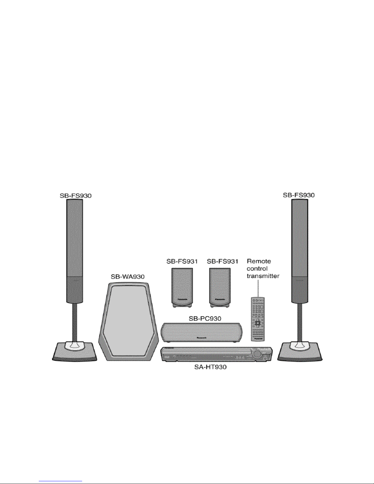
5-DVD Changer Home Theater System
SC-HT730, SC-HT930 Models
Practical Servicing of
B02
1

g
Prepared by
Herb Chin, & Joe Blanks
Panasonic Services Company
National Training
Panasonic is a registered trademark of Panasonic North America
"HDMI, the HDMI logo and High-Definition Multimedia Interface are trademarks or registered trademarks of HDMI Licensing LLC."
BBE, the BBE logo, Sonic Maximizer and High Definition Sound are registered trademarks or trademarks of BBE Sound, Inc.
Photoshop is a registered trademark of Adobe Systems Incorporated in the United States or other countries.
Dolby is a registered trademark of Dolby Laboratories.
DTS is a re
Copyright © 2006 by Panasonic Services Company
All rights reserved. Unauthorized copying and distribution is a violation of law.
istered trademark of Digital Theater Systems Corporation.
Warning
This service information is designed for experienced repair technicians only and is not designed for use by
the general public. It does not contain warnings or cautions to advise non-technical individuals of potential
dangers in attempting to service a product. Products powered by electricity should be serviced or repaired
only by experienced professional technicians. Any attempt to service or repair the product or products
dealt with in this service information by anyone else could result in serious injury or death.
SA-HT730 / SAHT930
2

Table of Contents
OBJECTIVE............................................................................................................................. 4
I NO START-UP AND DVD TRANSPORT PROBLEMS................................................. 5
1. POWER-ON START-UP SEQUENCE – WHERE IS THE PROBLEM?........................................... 5
2. SENSORS, BELTS, AND MOTOR LOCATION ............................................................................ 6
3. SIMULATED FAILURE SYMPTOMS – QUICK FIXES................................................................. 7
4. TRAY REMOVAL FOR SENSORS, BELTS, & DIAGNOSTIC ACCESS......................................... 8
5. TRAY INSTALLATION (AFTER REPAIRS)................................................................................ 9
6. SENSOR TESTING ............................................................................................................... 10
Testing the Tray Loading Motor and Related Sensors .................................................... 10
Testing the Tray Rotation Motor and Related Sensors.................................................... 11
II SHUTDOWN PROBLEM................................................................................................ 12
PROTECTION CONCEPT – ALL THE SHUTDOWN POSSIBILITIES................................................12
Overall Repair Strategy ................................................................................................... 12
CONTROL UNIT REPAIR (SA-HT730 / SA-HT930) STRATEGY ............................................. 13
Control unit repair Procedure......................................................................................... 14
Jumper Paths to System Control IC2018 for Shutdown Problems.................................. 15
Control Unit Protection Concept.....................................................................................16
SUBWOOFER UNIT REPAIR (SB-WA730 / SA-WA930)........................................................17
Subwoofer Repair Strategy – Start by isolaating the problem......................................... 17
Subwoofer Repair Procedure........................................................................................... 18
Subwoofer Disassembly ................................................................................................... 20
Subwoofer Test / Operating Position............................................................................... 21
III NO AUDIO PROBLEMS ...............................................................................................22
How to trace down no audio (one or more channels)...................................................... 22
SA-HT730 / SAHT930
3

Objective
This technical guide was prepared with the following objectives in mind:
• Provide the servicer with a brief overview of the concepts of operation for new
circuits employed in this line of models.
• Provide drawings with emphasis on signal path to simplify the task of signal
tracing and to locate the cause of a defect.
• Furnish troubleshooting procedures that contribute to a speedier repair of the
product.
• Provide examples of typical problems that may have occurred in similar types of
circuits.
SA-HT730 / SAHT930
4

I No Start-Up and DVD Transport Problems
Model: SA-HT730 / HT930. Since this unit normally starts in DVD mode, start-up
symptoms are often caused by DVD transport problems – A failure in the DVD
transport stops the start up.
Servicing the DVD section is divided into 6 groups (pick and choose what you need):
1. Power-On Sequence 4. Tray Removal for Diagnostic Access
2. Sensors, Belts and Motor Location 5. Tray Installation (after Repairs)
3. Simulated Sensor Failure Symptoms 6. Sensor testing
Start with the power-on sequence. The power-on sequence is important for
identifying the section that does not start. Compare the sequence in the defective
unit to the correct sequence listed below in table 1. The step where the unit stops
working is where the problem is (or in the step just before). Testing the sensors is
the next diagnostic step (section 6) if the transport works but behaves out of
sequence. Section 2 locates the sensors. However access to the sensors for testing
is tricky but the trick is revealed in section 4 - tray removal. After repairs, section 5
shows how to align the gears for reassembly.
1. Power-On Start-Up Sequence – Where is the problem?
After AC is disconnected, the unit always powers on into the DVD operation mode.
SA-HT730 / HT930 Power ON sequence
Step Time Operation Display Proof
1. 0 AC input. Unit off.
2. 0 Press Power button Disc # 1-5 light in sequence.
3. 1 sec “Hello”
4. 4 sec Micro IC8001 controls laser
assembly via cable to
CN2004. See table 2.
5. 5 sec Loading motor moves the
Tray in (if S9001 is not open)
and into the disc unchucked
position using two loading
sensors.
No movement will occur if the
transport is already in this tray
in unchucked position.
6. 8
sec.
7. 17 Tray motor stops at original
1. Disc Tray motor rotates.
Slow rotation is first.
2. Detection of discs on platter
/ tray.
disc slot.
None
appears
“INIT” appears
“Please Wait”
“Please Wait”
“ No Disc”
Table 1
Red light over pwr button
(standby).
All disc numbers 1-5 light.
Disc proof sequence is followed *
see table 2.
Two loading sensors are used:
1. S9001 = contacts open / tray
closed. Contacts are open if the
Tray is in.
2. Q9001 at CN2011/6 = 0Vdc =
non-clamped position (tray
rotation is possible when the
disc assembly is unclamped.)
1. S9102 detects tray motor gear
rotation.
2. Q9103 detects each disc when
the disc blocks the Q9103 light.
S9101 also detects tray rot.
position.
SA-HT730 / SAHT930
5
* Disc Proof Sequence (no disc loaded)
a) Sled moves to home position (at
center).
b) Sled moves out to DVD TOC
location.
c) Laser ON. h) Focus search 3X. 3. Volts missing
d) Focus search 3X. (spins if disc is
found)
e) Sled moves to home position (at
center).
f) Sled moves out to DVD TOC
location.
g) Laser ON. 2. Mechanical
i) Sled moves to home position 4. Traverse
j) Sled moves out to initial position. 5. IC8251 –
Table 2
Checkout
Failure
1. Ribbon cable
binding
Motor
motor drive
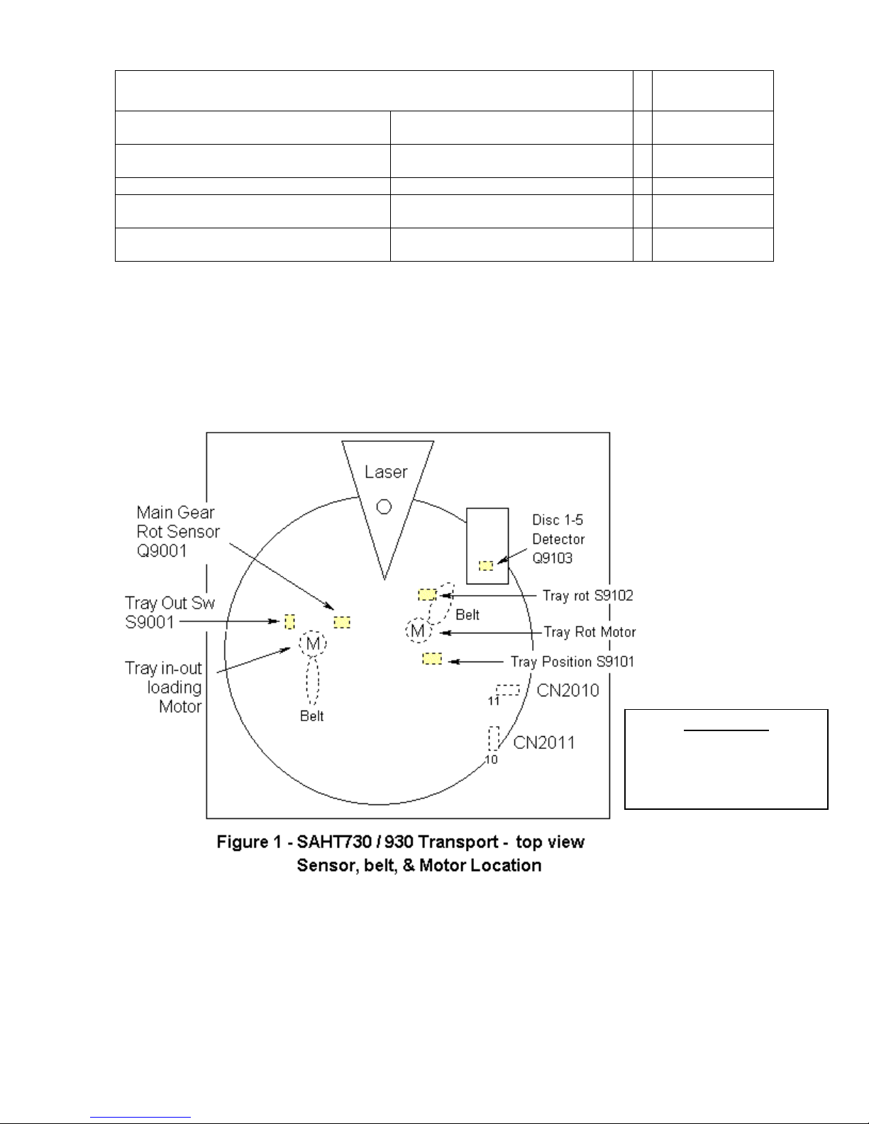
2. Sensors, belts, and motor location
Items in dotted lines are under the tray. Since many parts are under the tray, the tray
must be slid out to test the parts. This is easier than it looks. Use disassembly section
4 to access the parts shown below.
SA-HT730 / SAHT930
Part numbers
Tray Belt = RDV0073
Loading Belt = RDV0073
Loading Motor = REM0112
Tray Motor = same as above
6

3. Simulated Failure Symptoms – quick fixes
Although sensor failures cause the following symptoms listed in table 3, the more
common failure is an internally broken ribbon cable that carries the sensor signal to
the microprocessor.
To determine which is at fault, begin testing using figures 4 and 5 or order the cable
with the corresponding sensor. For example the motors (#6 & #7 in table 3) and
S9001 (#4) can be quickly checked with an ohmmeter at the CN2010/2011 cable end
(see figures 4 or 5). If the part tests bad bypass the cable and recheck the part right
at the part’s terminal.
CN2010 ribbon cable p/n = REZ1484 (11 pins)
CN2011 ribbon cable p/n = REZ1483 (10 pins)
Simulated Failures
Sensor Cable Symptom Comments
1. Disc Det Q9103
open
2. Tray rotation Q9102
open.
3. Tray position
Q9101 open.
4. Main gear position
Q9001 open.
5. Tray out switch
S9001 open.
6. Tray Loading Motor CN2011 Front panel display = “Please Wait” or
7. Tray Rotation Motor CN2010 Front panel display = “Please Wait”
CN2010 No disc detected (no PB possible).
CN2010 Tray motor rotates back & forth for ¼ rotation then
shuts down. H01 error code shown.
CN2010 Slow continuous CCW rotation of the tray. “INIT”
appears and no buttons work except power.
CN2011 Tray moves out and spins, then the tray moves in.
and the mech clamps & then unclamps. Repeats.
CN2011 Normal start up. Pressing the open tray button
permits the tray to open but it closes
automatically.
“Open/Close”
Table 3
Unit shuts
down.
Unit does not
shutdown.
Unit does not
shutdown.
Tray will not
stay open.
Motor = 14
ohms
SA-HT730 / SAHT930
7
 Loading...